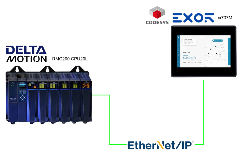
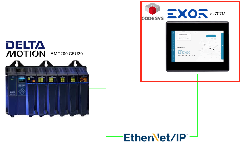
This article will configure the Codesys on the EXOR ex707M and Delta Motion’s RMC200 CPU20L via an Ethernet/IP connection.
Alright, let’s enjoy the FA!
Foreword
Thank you from the bottom of my heart for visiting my technical blog and YouTube channel.
We are currently running the “Takahashi Chris” radio show with Full-san (full@桜 八重 (@fulhause) / X) which I deliver every Wednesday night.
Sharing, not hoarding, technical knowledge
We publish technical information related to factory production technology and control systems for free, through blogs and videos.
With the belief that “knowledge should be accessible to everyone,” we share practical know-how and real-world troubleshooting cases from our own field experience.
The reason we keep it all free is simple: to help reduce the number of people who struggle because they simply didn’t know.
If you’ve ever thought:
- “Will this PLC and device combination actually work?”
- “I’m having trouble with EtherCAT communication—can someone test it?”
- “I want to try this remote I/O, but we don’t have the testing environment in-house…”
Feel free to reach out!If lending equipment or sharing your configuration is possible, we’re happy to verify it and share the results through articles and videos.
(We can keep company/product names anonymous if requested.)
How can you support us?
Currently, our activities are nearly all unpaid, but creating articles and videos takes time and a proper testing environment.If you’d like to support us in continuing and expanding this content, your kind help would mean a lot.
Membership (Support our radio show)
This support plan is designed to enhance radio with Mr Full.
https://note.com/fulhause/membership/join
Amazon Gift List (equipment & books for content production)
Lists equipment and books required for content creation.
https://www.amazon.co.jp/hz/wishlist/ls/H7W3RRD7C5QG?ref_=wl_share
Patreon (Support articles & video creation)
Your small monthly support will help to improve the environment for writing and verifying articles.
https://www.patreon.com/user?u=84249391
Paypal
A little help goes a long way.
https://paypal.me/soup01threes?country.x=JP&locale.x=ja_JP
Just trying to share things that could’ve helped someone—if only they’d known.
Your support helps make knowledge sharing more open and sustainable.
Thank you for being with us.
soup01threes*gmail.com
Technical knowledge shouldn’t be kept to ourselves.
Reference Link
http://soup01.com/en/category/deltamotioncontrol_en/
http://soup01.com/en/category/protocol-en/ethernet-ip-en/
Ethernet/IP
EtherNet/IP is an open application protocol maintained and distributed by ODVA. EtherNet/IP is used by Ethernet modules for several PLCs including Allen Bradley, Schneider Electric, and Omron. EtherNet/IP is an Ethernet adaptation of the Control Information Protocol (CIP), in the same way that DeviceNet is a CAN adaptation of CIP and ControlNet is a CTDMA adaptation of CIP.
The RMC is a passive EtherNet/IP device. It does not establish its own I/O connections, nor does it initiate messaging transactions. Therefore, an active EtherNet/IP device or client is required to control the RMC or request data from the RMC.
The RMC75E, RMC150E, and RMC200 support EtherNet/IP Messaging and EtherNet/IP I/O.

EtherNet/IP Messaging
EtherNet/IP explicit messaging allows the originator (PLC or HMI) to request individual services from the target device (RMC). These requests are made explicitly rather than being scheduled cyclically like I/O. Explicit messaging is much more flexible than I/O in terms of what data or services are accessed in the target device, since I/O connections must pre-configure the I/O data to be exchanged.
In most cases, RMC users use EtherNet/IP explicit messaging to read and write registers in the RMC. Also, some advanced EtherNet/IP users may want to access standard CIP services and attributes.
The three types of EtherNet/IP explicit messaging services available in the RMC are:
- Read and/or write RMC registers using the Allen-Bradley PCCC/DF1 services.
- Read and/or write RMC registers using the Register Map Object.
- Access standard CIP services and attributes.
EDS Files
EDS (Electronic Data Sheet) files are used by many vendors’ EtherNet/IP configuration tools to help configure the communications.
Connection Type
The RMC supports three types of I/O connections. Of these three, the Input/Output connection type is by far the most commonly used. The other two are generally only used when multiple I/O connections are used.
Input/Output
This connection is bidirectional: the originator (PLC or HMI) produces data consumed by the RMC and the target (RMC) produces data that is consumed by the originator. This connection type is also called an Exclusive Owner connection or the controlling connection.
Input Only
For this connection type, only the target (RMC) produces data, which is consumed by the originator (PLC or HMI). The originator will only send a heartbeat packet, sometimes at a reduced interval (less frequently than the RPI) used to allow the RMC to identify when the connection is broken.
Listen Only
This connection type is identical to an Input Only connection type, with one exception: a Listen Only connection can only exist when one of the other I/O connection types has been established. That is, a Listen Only connection cannot be established until an Input/Output or Input Only connection has been established, and conversely when the last non-Listen-Only connection has been closed or has timed out, the Listen Only connection will automatically close as well. This connection type is the least-frequently used and is not supported by RMC75/150 firmware version 3.40.x or older.
Max Number of Connections and Data
Connection Type | RMC75E | RMC150E | RMC200 |
|---|---|---|---|
Total I/O Connections | 4 | 4 | 4 |
Input/Output Connections | 1 | 1 | up to 3 |
Input Only Connections | up to 4 | up to 4 | up to 4 |
Listen Only Connections | up to 4 | up to 4 | up to 4 |
Connection #1 Size | 125 input registers / 124 output registers | 125 input registers / 124 output registers | 360 input registers / 360 output registers |
Connection #2 Size | n/a | n/a | 125 input registers / 124 output registers |
Connection #3 Size | n/a | n/a | 125 input registers / 124 output registers |
Requested Packet Interval (RPI)
EtherNet/IP I/O sends data between the communicating devices at the Requested Packet Interval (RPI). The RPI is configured in the EtherNet/IP controller (for example, RSLogix 5000), not in RMCTools. The RMC supports the following RPIs, based on the number of simultaneous I/O connections established.
I/O Connections | Minimum RPI RMC75/150 | Minimum RPI RMC200 CPU20L | Minimum RPI RMC200 CPU40 | Typical RPI | Maximum RPI |
|---|---|---|---|---|---|
1 | 2 ms | 1ms* | 1ms | 20 ms | 10,000 ms |
2 | 3 ms | ||||
3 | 4 ms | ||||
4 | 4 ms |
The RPI must be both an integer number of milliseconds and a multiple of the RMC’s Loop Time. For example, an RPI of 9 ms would not be allowed for a loop time of 2 ms or 4 ms, but would be for 1 ms or lower loop times.
Delta recommends using the slowest RPI that meets the requirements of your application in order to reduce network requirements.
Loop Time
The RMC is a deterministic controller. It reads the inputs, computes the control algorithms and updates the outputs at a specific interval. This interval is called the controller loop time, in reference to the way the controller repeatedly “loops” through its code.
The RMC will always run at its loop time setting. When it finishes all the calculations for one loop, it waits until the next loop time before doing its calculations again.
Multicast vs. Point-to-Point (Unicast)
The RMC supports both multicast and unicast (point-to-point) I/O connections. In almost all cases, unicast I/O connections should be selected whenever supported by the EtherNet/IP I/O controller, in order to reduce network traffic.
The RMC75/150 requires multicast I/O connections only when multiple I/O connections will be established at once, which is quite rare. The RMC200 allows multiple unicast I/O connections.
Input Data
The Input Data is the data produced by the RMC and sent to the PLC. By default, the source of the Input Data is the Indirect Data Map, beginning with Indirect Data Map item 0.
First, you must set up the Indirect Data Map in RMCTools to map to the RMC registers you want to transfer. Typically, you would include Actual Positions, Status and Error Bits for each axis of control, task status registers so the PLC can tell which user programs are running, and any other registers of your choice.
The Input Data source can be changed to something other than the Indirect Data Map, as described below, but the Indirect Data Map is used in nearly all EtherNet/IP I/O applications.
The size of the Input Data is specified in the PLC when configuring the EtherNet/IP I/O connection.
Once an EtherNet/IP I/O connection is established, the Input Data will automatically be sent from the RMC to the PLC each RPI. The PLC can use the data whenever it needs it.
Output Data
The Output Data is the data sent from the PLC and consumed by the RMC. By default, the destination of the Output Data is the Indirect Data Map. This allows the PLC to easily write to whatever registers you have mapped into the Indirect Data Map, such as variables and axis command registers.
The destination of the Output Data can be changed to something other than the Indirect Data Map registers, but the Indirect Data Map works very well for most applications.
The size of the Output Data is specified in the PLC when configuring the EtherNet/IP I/O connection. The Output Data size must be the number of registers you wish to write, plus the Sync Register, if used.
Once an EtherNet/IP I/O connection is established, the Output Data is used to write to the RMC.
Note – Unicast I/O Connections
Always use unicast I/O connections instead of multicast whenever possible. Notice that Allen-Bradley products only supported multicast connections prior to RSLogix 5000 v18.
Note – Appropriate RPI
Do not use a lower RPI than you need. Usually an RPI of 10 ms or 20 ms is sufficient. Lowering the RPI will increase the load on every Ethernet component in the system, and beyond a certain point has no benefit. For example, if the RPI is lower than the scan time of the controlling PLC, then additional packets will not benefit the system.
Note – Switch Related
Never use hubs or other half-duplex switchgear. This will introduce collisions, which greatly reduce the scalability and determinism of a network.
When using a multicast connection, never connect the EtherNet/IP I/O network to a general purpose network, except through a router. The multicast traffic on the EtherNet/IP network will be noticed by your IT department. Conversely, glitches on the general purpose network could affect your factory network. If only unicast I/O connections are used, then connecting to a general purpose network through a switch may be acceptable in some applications.
Bandwidth Issues
If the total bandwidth required exceeds 90% of the EtherNet/IP I/O controller’s bandwidth, then you will have to consider one of the following options:
Increase the RPI for one or more of the RMC connections
Increasing the RPI reduces the required bandwidth. For example, doubling the RPI will cut the bandwidth in half. Notice that in many cases, increasing the RPI comes at no cost to the system performance because the PLC may be unable to scan its ladder logic as frequently as the RPI.
Replace the EtherNet/IP controller with a faster model
If an EtherNet/IP controller with higher bandwidth is available for the same platform, then you may be able to upgrade the EtherNet/IP controller.
Use multiple EtherNet/IP modules to divide the network
By adding one or more additional EtherNet/IP communication modules to the PLC, each with its own isolated network with a smaller number of RMCs, the bandwidth requirement on each device is reduced. Notice that it is important that the individual networks are not connected to one another directly or through a switch, as this will largely defeat the benefits of dividing the network.
Network Performance
The maximum amount of information that 100 Mbps Ethernet can carry in one direction is 100 million bits per second. If all packets on the network were EtherNet/IP I/O packets of the largest size supported by the RMC (125 four-byte REALs), then this would be a maximum of 21,600 packets/second (notice that packet overhead such as headers and inter-frame spacing are included in this estimate). The network utilization should be kept well below this maximum. As the utilization approaches the maximum, it becomes more and more likely that a packet will have to wait to get onto the wire, introducing small delays.
Packet Processing
In addition to the limits of the wire itself, many devices have a maximum sustained rate that they can receive packets without falling behind in packet processing and eventually dropping packets. The RMC is one such device, since priority must be given to controlling motion above handling packets. No pre-determined maximum rate is currently available, but by reviewing the Ethernet Statistics in the devices, you can look to see if packets are being discarded.
EtherNet/IP Multicast I/O Connections
Notice that EtherNet/IP multicast I/O connections can greatly impact the performance of an Ethernet network since—unlike unicast packets, which are sent directly to a single device—multicast packets are sent to all devices on the network by default. This increases the load on every device, including the switches, and each individual network segment.
If your network has a high utilization and/or network components are dropping packets due to high packet rates, you will want to look at ways of reducing the network utilization. There are three ways to reduce the network utilization:
Change multicast I/O connections to Unicast
Multicast I/O connections can significantly increase the network load. Most applications do not require multicast I/O connections, and all I/O connections should be set up as unicast.
Increase the RPI for one or more EtherNet/IP I/O connections
The simplest way to reduce network utilization is to increase the RPI of EtherNet/IP I/O connections. Of course, this is only a possibility if the RPIs are unnecessarily low.
Use multiple EtherNet/IP modules to divide the network
By adding one or more additional EtherNet/IP communication modules to the PLC, each with its own isolated network with a smaller number of RMCs, the utilization on each sub-network is reduced.
Implementation
Let’s start to configure our project.
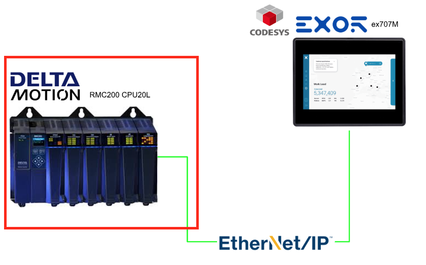
Delta Motion Side
First, we will build from the Delta Motion Controller RMC200 side.
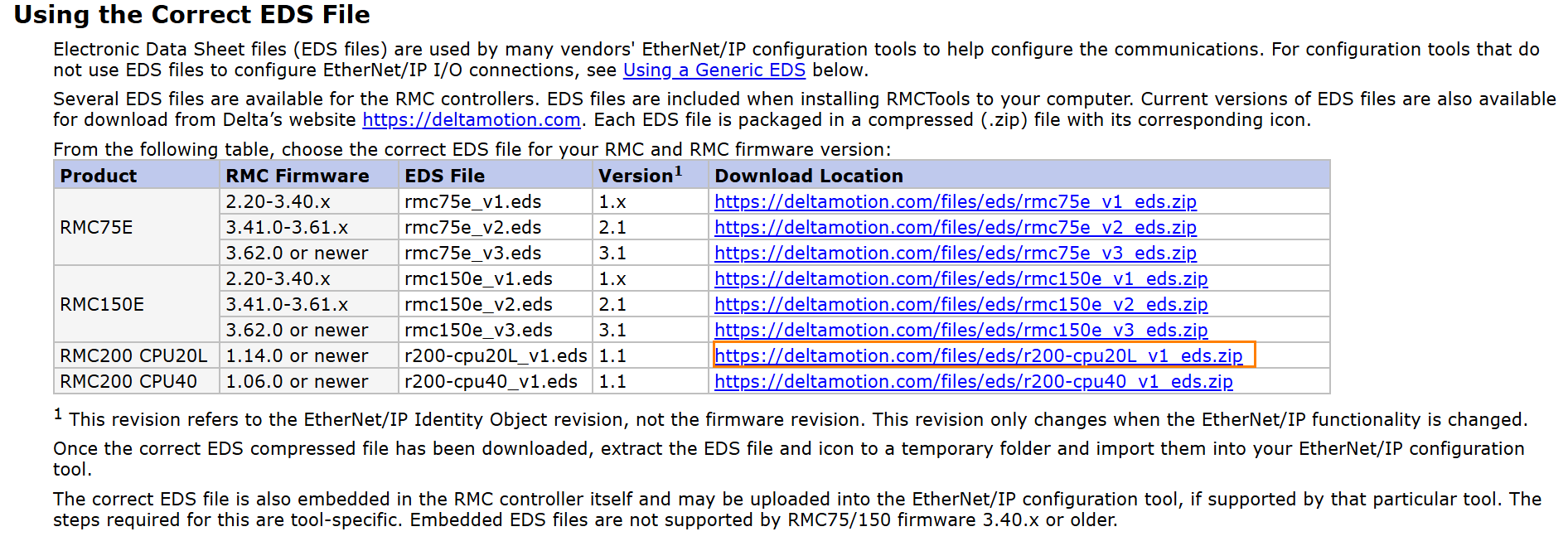
Download EDS File
Please download the EDS file from Delta Motion’s website.
Configuration
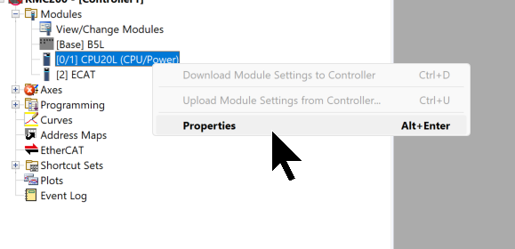
Next, launch RMC Tools, then click Modules → CPU → right-click → Properties.
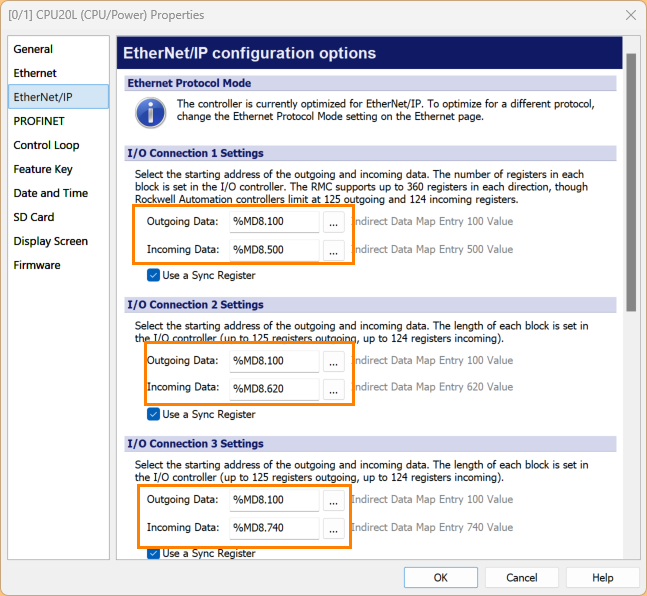
Open the Ethernet/IP Menu.
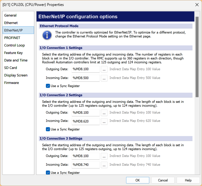
Set the starting address for the input/output data of the three connections.
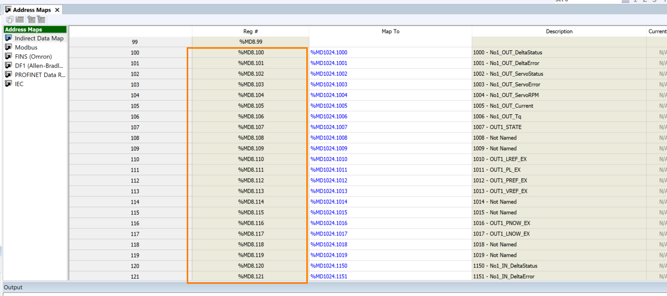
You can actually verify that address using Address Maps.
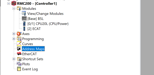
You can check it from Reg# as shown in the figure below.
Codesys Side
Next, we will set up the Codesys side.
Install EDS File
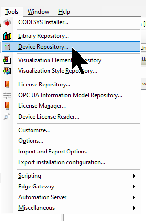
To install the EDS FILE for the RMC200, click Tools → Device Repository.
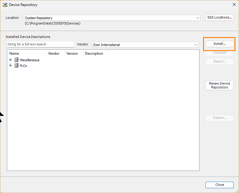
Click the Install button.
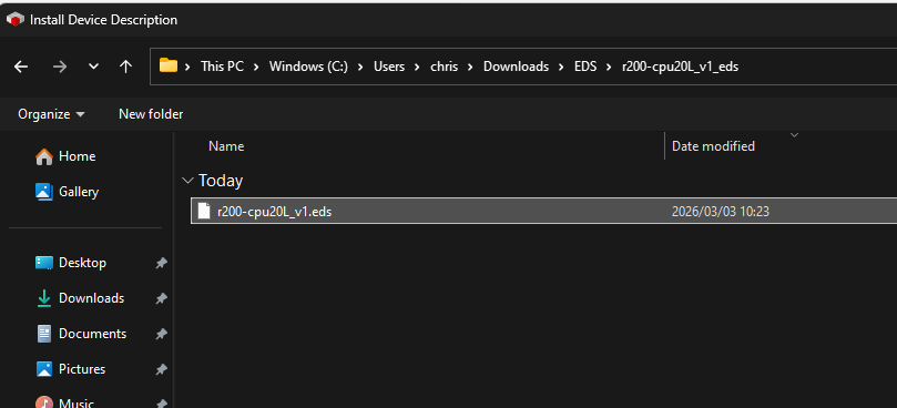
Select the EDS file you downloaded earlier.
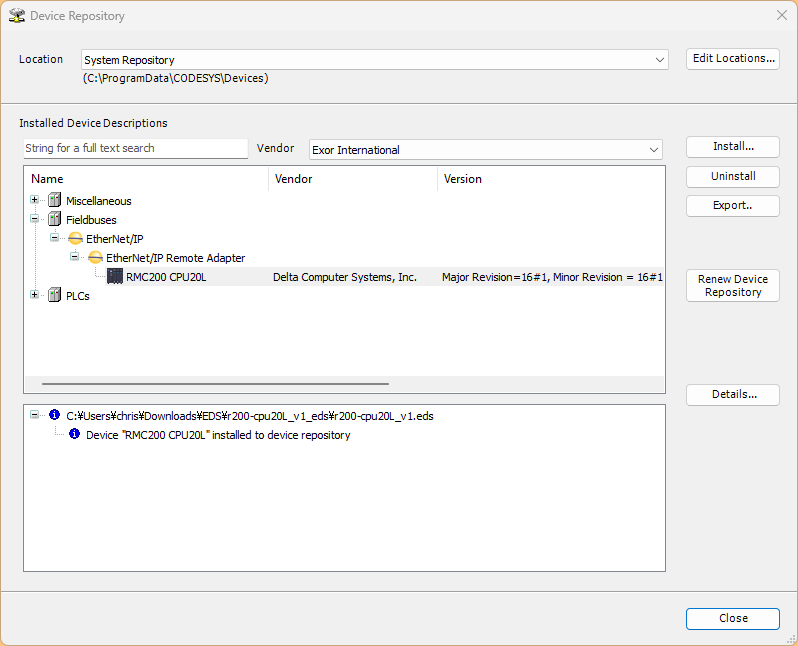
Done!The EDS file for RMC200 has been successfully installed.
Add the Ethernet Interface
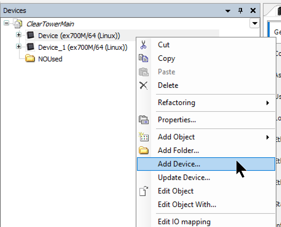
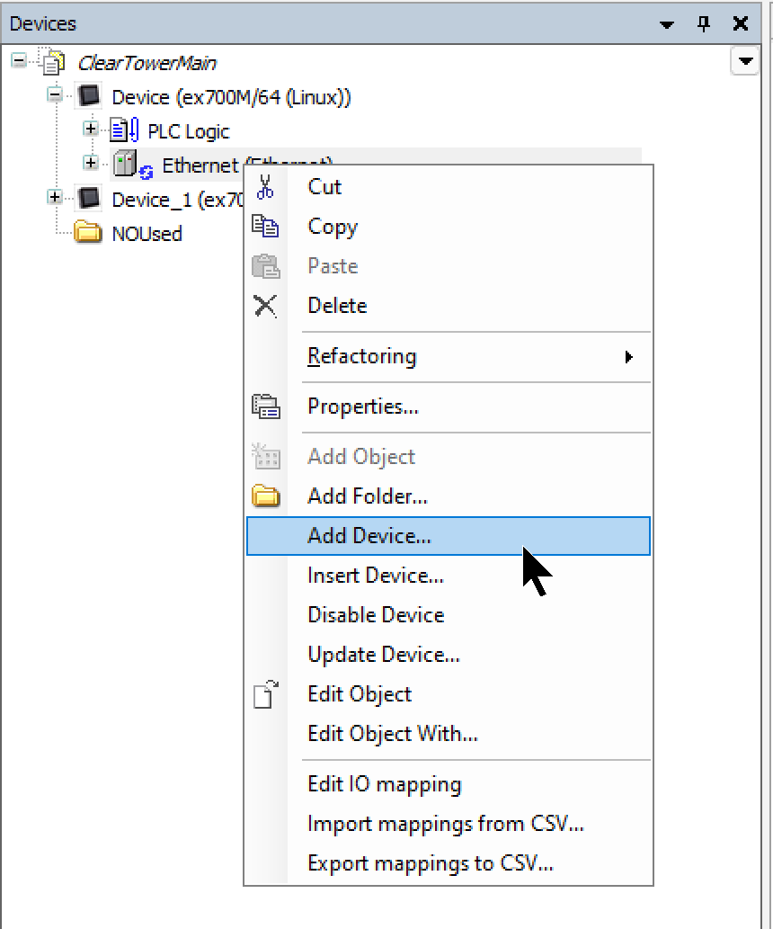
Right-click Device → Add Device.
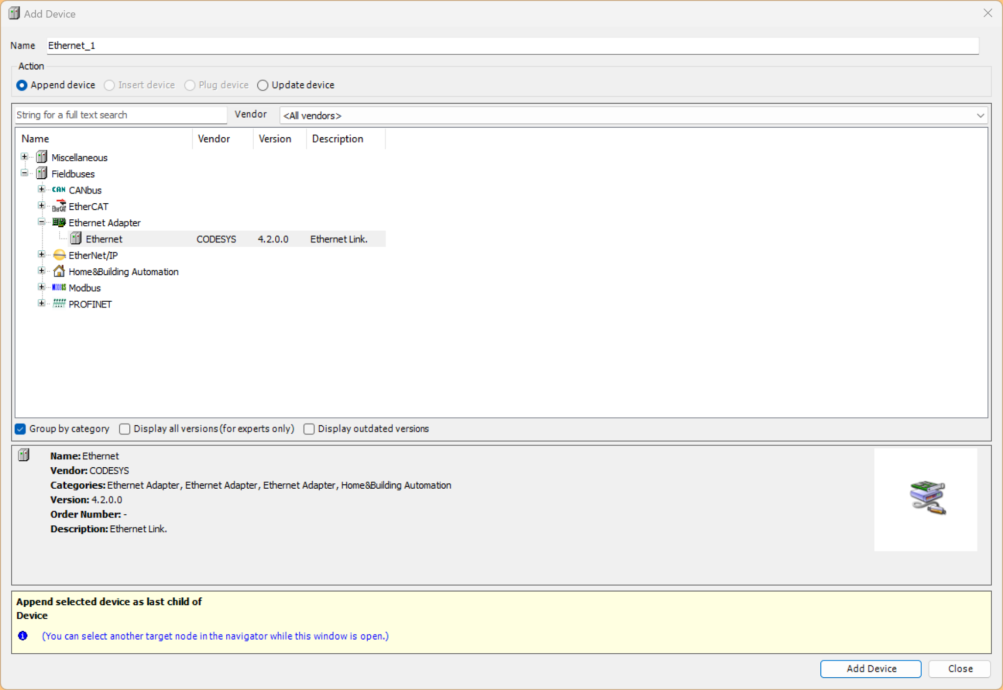
Click Ethernet Adapter→Ethernet to add an Ethernet interface.
Add the Ethernet/IP Scanner
Next, right-click the Ethernet interface and select Add Device.
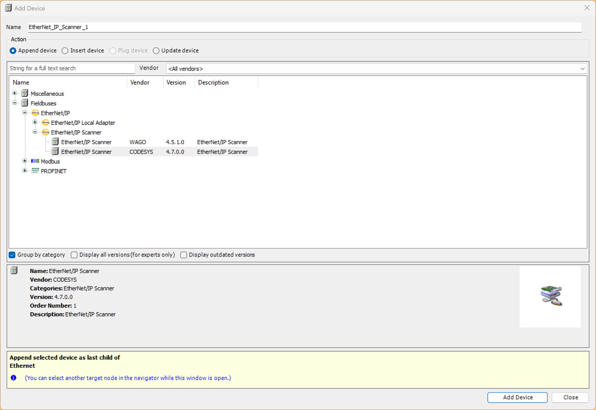
Select the Ethernet/IP Scanner → Add Device.
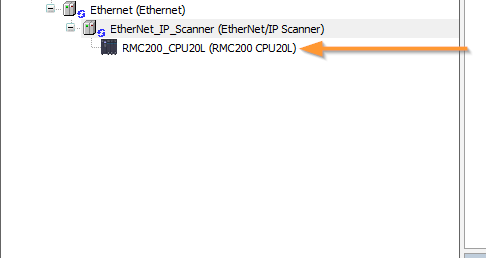
Add RMC200
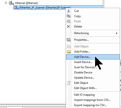
Finally, to add the Delta Motion RMC200 used in this article, right-click on the Ethernet/IP Scanner and select Add Device.
Select RMC200.
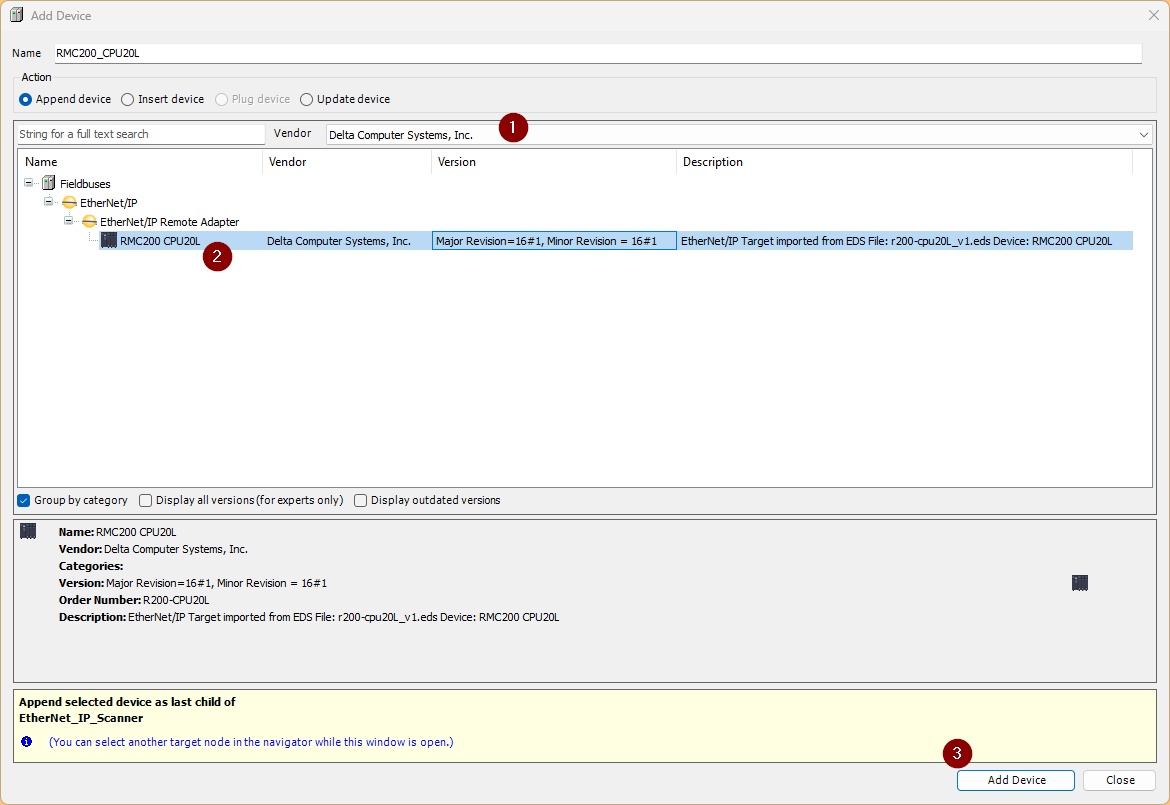
Done!
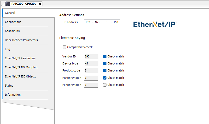
IP
Click the RMC200 you just added, then under General → IP address, set it to match the RMC200’s IP address.
Connection
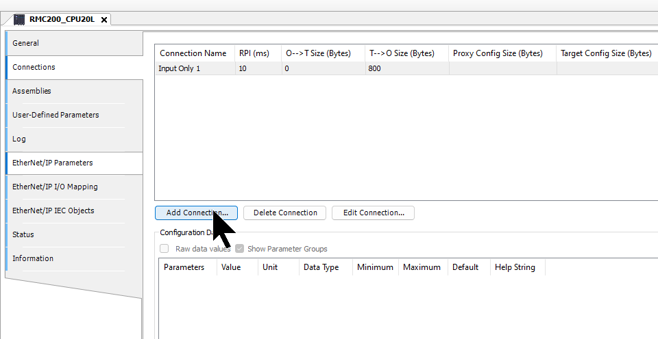
Next, open the Connection tab.
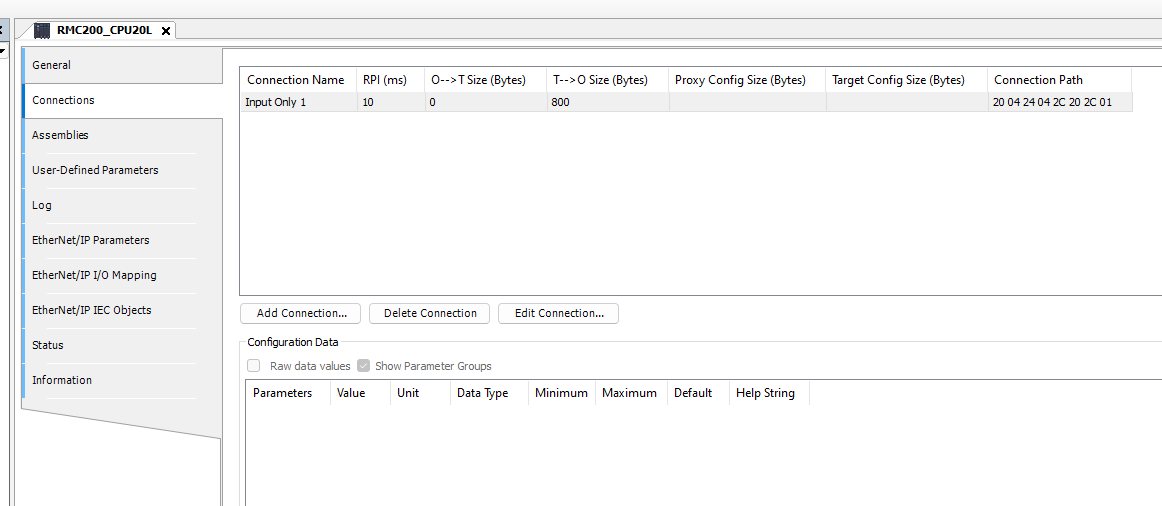
Add a new connection using Add Connection.
Set the connection type and data exchange size according to your application.
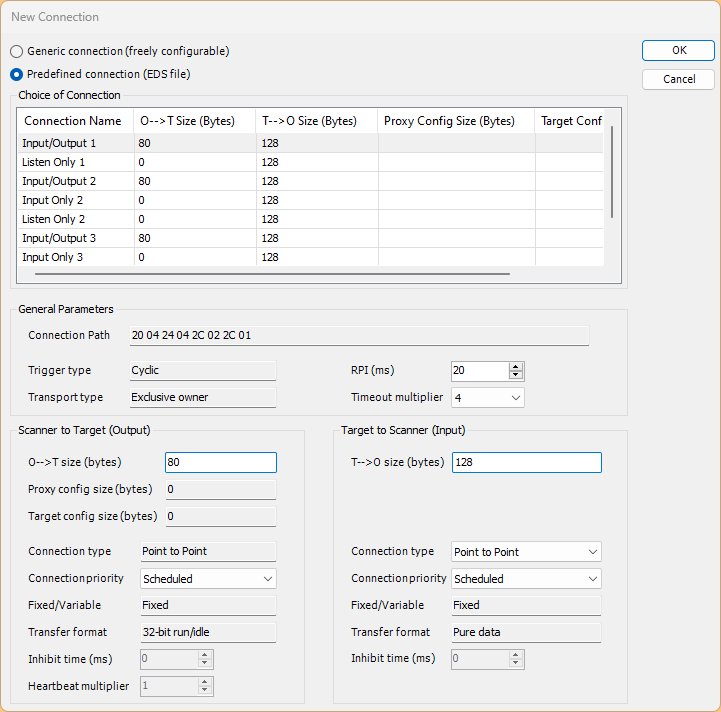
In this article, we will add Input Only1 and set its size to 800 bytes.

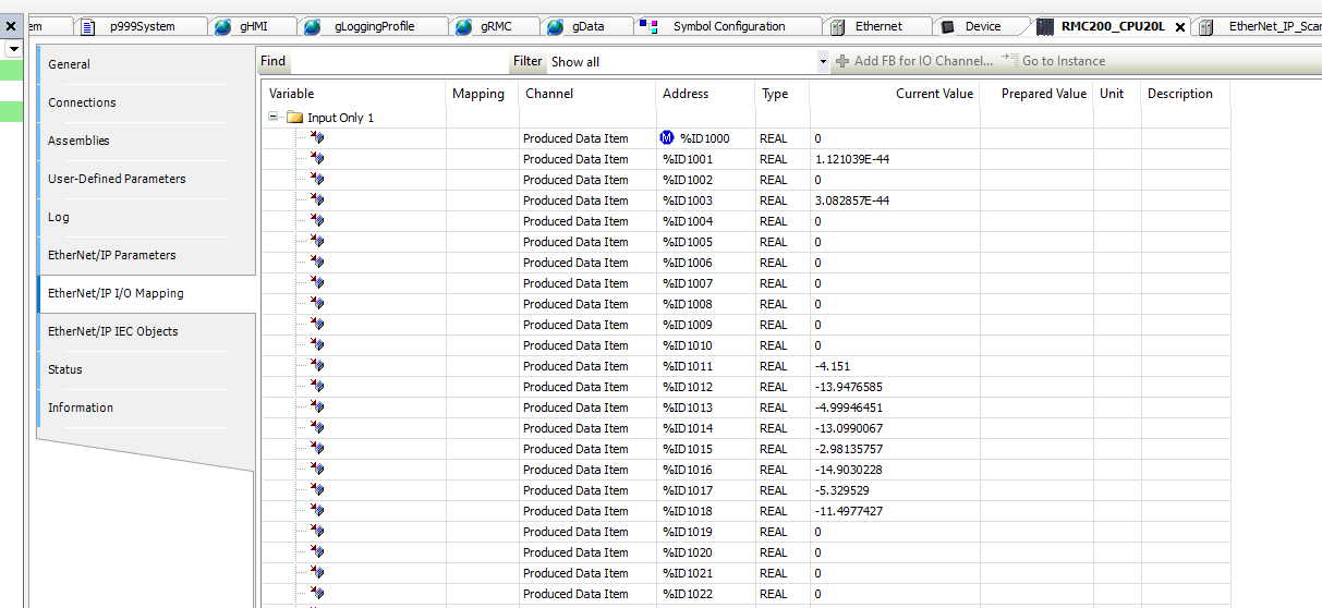
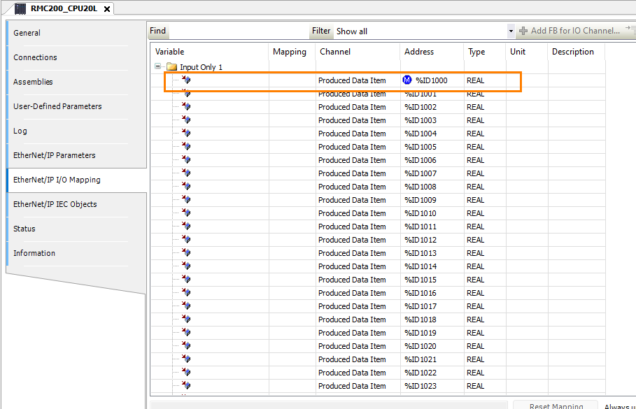
Mapping
This time, open the Ethernet/IP I/O Mapping tab and set the destination address to a fixed address.
Program
Next, we will create the program.
DUT
stRMC300Real
stRMC300Real is a structure containing an array capable of storing 200 REAL-type values. It defines EtherNet/IP I/O data exchange with RMC via the indirect data map.
TYPE stRMC300Real :
|
|---|
stRMC300Real_2
stRMC300Real_2 is a structure containing axis data for 8 axes (of type stRMC1AxisData) and a 40-element reserve REAL array. It is a type definition for managing each axis’s data grouped by axis. Compared to the flat array of stRMC300Real, it provides a structure that facilitates easier access on an axis-by-axis basis.
TYPE stRMC300Real_2 :
|
|---|
uRMCInputs300Real
uRMCInputs300Real is a UNION type, and raw and stData share the same memory area. This allows two different access methods for the same data.
TYPE uRMCInputs300Real :
|
|---|
stRMC1AxisData
stRMC1AxisData is a structure that stores RMC data for one axis. It consists of 20 REAL-type members and is used as the element type for the dutArrAxis array in stRMC300Real_2. 8 axes × 20 elements = 160 registers; the remaining 40 elements become ArraySpare, totaling 200 registers.
TYPE stRMC1AxisData :
|
|---|
GVL
conn1IN is a UNION-type variable declared as a global variable, with %ID1000 directly mapped to the input address of the EtherNet/IP I/O. The input data received from the RMC, consisting of 200 registers, can be accessed in the following two ways:
- Flat array access: conn1IN.raw.rArray[0]
- Axis-specific structure access: conn1IN.stData.dutArrAxis[0].ServoRPM
VAR_GLOBAL
|
|---|
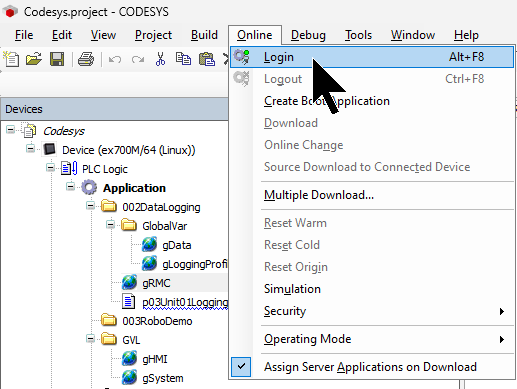
Download
Finally, download the project to the Codesys Runtime.
Result
Done!Ethernet/IP communication between Codesys Runtime and RMC200 has been established.
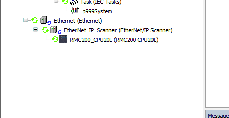
Data received from RMC200.