In this Tutorial Series, we will build a Profisafe network using Pilz’s PDP67 PN 6FDI 6FDIO 2FDOTP.In the Part1,I will provide a brief introduction to PDP67 PN 6FDI 6FDIO 2FDOTP and basic start-up procedures.
Let’s get started!
Reference Video
Here is a video of myself introducing Pilz’s PDP67 PN 6FDI 6FDIO 2FDOTP.
Pilz.PDP67 PN 6FDI 6FDIO 2FDOTP Introduction
Thanks!
PSSu H PLC1 FS SN SD is borrowed from Pilz Japan, Thanks !!
PILZ
PILZ supports FA sites as a total solution supplier with safety and automation technology solutions, guaranteeing not only human safety, but also machine and environmental safety, to ensure the safe operation of machines and equipment. Pilz has 42 local companies and branches worldwide and is active in various fields such as packaging, the automotive industry, robotics applications, as well as wind power and railway technology.

Office:
ピルツジャパン株式会社
〒222-0033
横浜市港北区新横浜3-17-5
いちご新横浜ビル 4階
HP
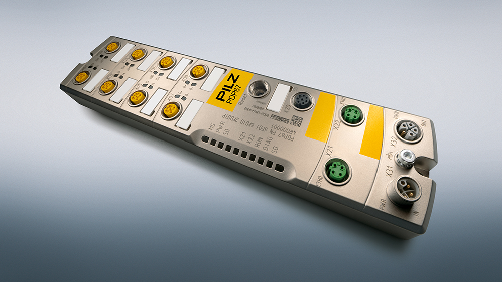
PDP67 PN 6FDI 6FDIO 2FDOTP?
The Pilz product PDP67 PN 6FDI 6FDIO 2FDOTP, launched in 2022, is a device with IP67 protection and IO ports for use in harsh industrial environments, allowing systems to be connected to PROFINET with the PROFIsafe profile. Its PDP67 PN 6FDI 6FDIO 2FDOTP has,
- PROFINET Conformance Class C
- Supports IRT/ RT
- Data set I&M 0-4
- Built-in Web Server and includes the following features
- Device Information
- Diagnostic Information
- Device Configuration
- Perform Wiring Test
- Up to 12 type FS inputs according to IEC 61131-2 in default configuration (X02, X04, X06 if configured as FS inputs)
- Up to six 1-pole digital FS outputs can be configured for three ports (ports X02, X04, and X06 when configured as FS outputs)
- Up to 12 1-pole ST outputs can be configured for 6 ports (ports X01 to X06 when configured as ST outputs)
- 2-port 2-pole digital FS output (X07, X08)
- Memory card allows backup of settings
System Layout
This is the System Layout for PDP67 PN 6FDI 6FDIO 2FDOTP. The PDP67 PN 6FDI 6FDIO 2FDOTP is basically divided into four Areas: I/O Area, Device Area, Fieldbus Area, and Power Area.
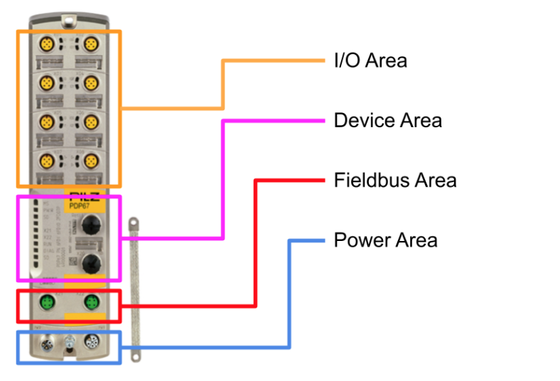
I/O Area
In the Default configuration of PDP67 PN 6FDI 6FDIO 2FDOTP, there are 12 FS inputs and 2 2-pole FS outputs. And the IO ports named IOX02, X04, and X06 are called hybrid IO ports and can be used as FS inputs or FS outputs depending on the configuration.
I/O ports (X01 … X08)
Each IO Ports has a status LED and a replaceable IO Port nameplate label.
Device Area
The Device Area has labels for the reset button, Memory Card Slot, LEDs on the device itself, and interchangeable IO ports.
Fieldbus Area
2 PROFINET ports (X21, X22) are available for RT/IRT communication.
Power Area
1 port for power voltage supply (X31), 1 port for power voltage distribution (X32) and ground connection.
Connecton Pin
The following describes the Port Pint for Pilz PDP67 PN 6FDI 6FDIO 2FDOTP.
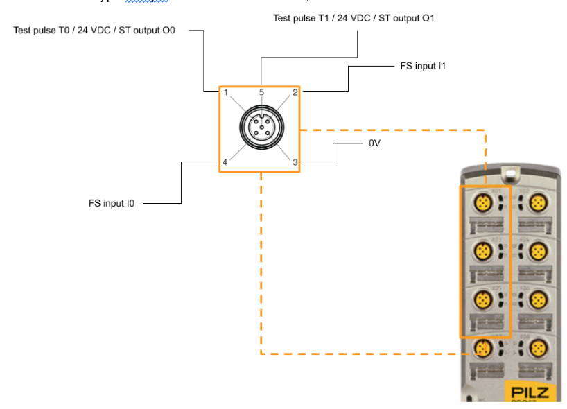
PortX1/X3/X5
The connector type is 5-pin M12 female connector, A-coded.
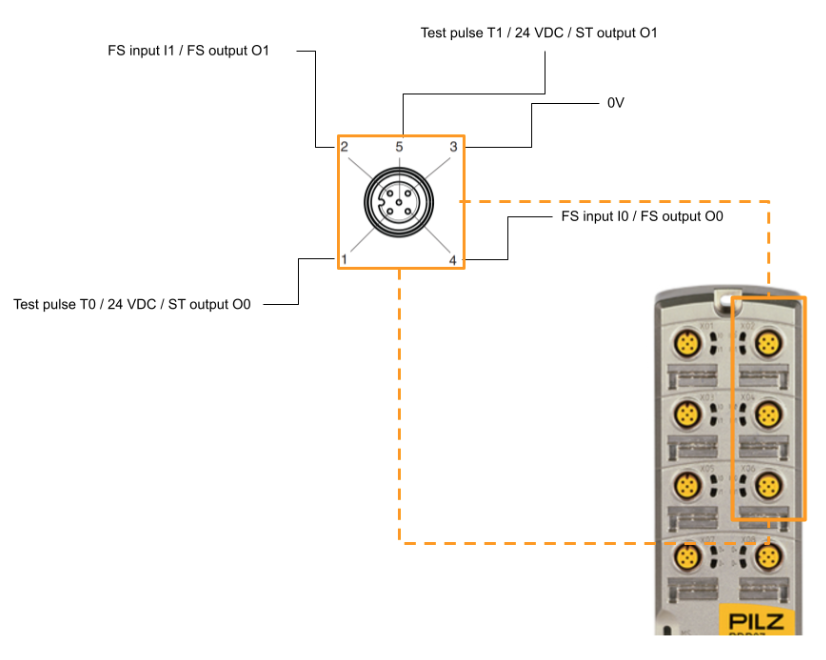
PortX2/X4/X6
The connector type is 5-pin M12 female connector, A-coded.
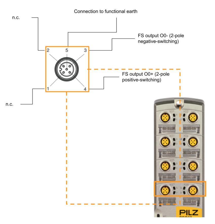
PortX7/X8
The connector type is 5-pin M12 female connector, A-coded.
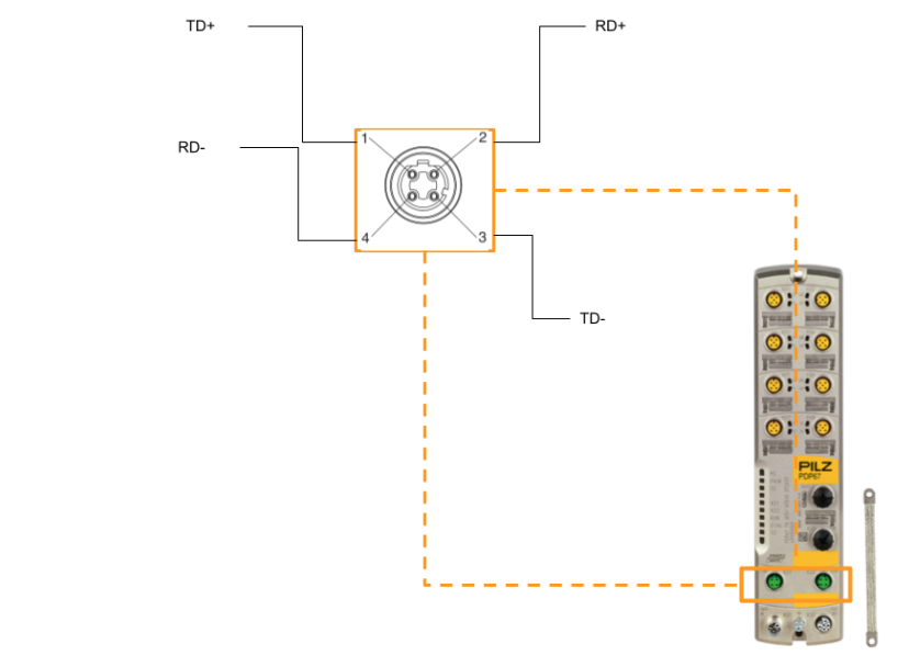
Port X21/X22
Ethernet Port, Connector Type is 4-pin M12 female connector D-coded.
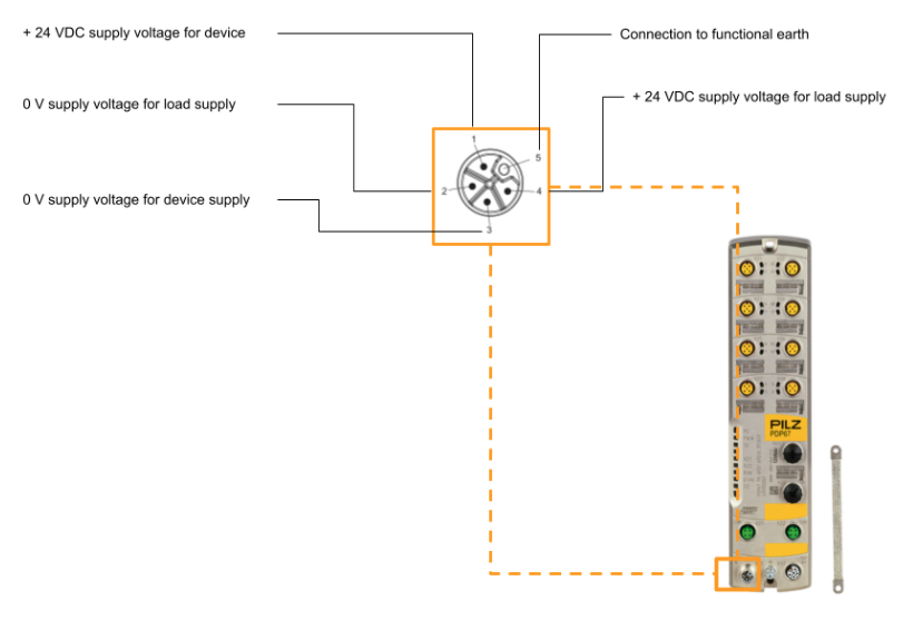
Port31
Power Port, Connector Type is 5 pin M12 male connector L-coded.
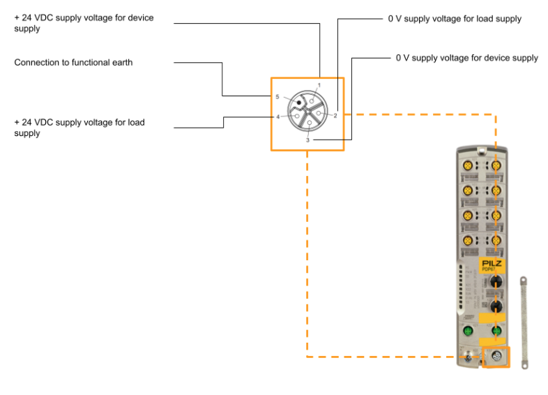
Port32
Power Port, Connector Type is 5 pin M12 female connector L-coded.
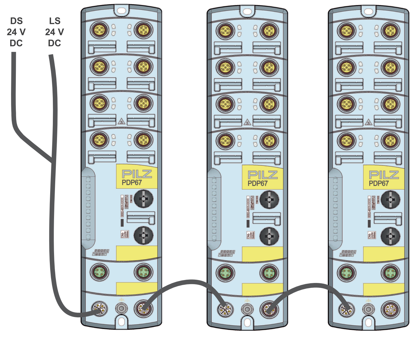
Routing
The figure below shows a wiring example when using multiple PDP67 PN 6FDI 6FDIO 2FDOTP.
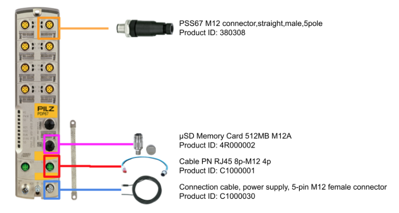
Basic Parts
When using PDP67 PN 6FDI 6FDIO 2FDOTP, it is easier to have the following Parts.
- PSS67 M12 connector,straight,male,5 pole
Product ID: 380308 - µSD Memory Card 512MB M12A
Product ID: 4R000002 - µSD Memory Card 512MB M12A
Product ID: 4R000002 - Connection cable, power supply, 5-pin M12 female connector
Product ID: C1000030
Base Tools
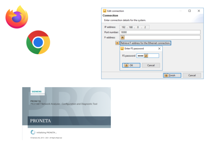
The only tools required to use PDP67 PN 6FDI 6FDIO 2FDOTP are Browser, Pasconfig, and a tool that can issue DCP Protocol (Proneta in this case).
Application Exmaple
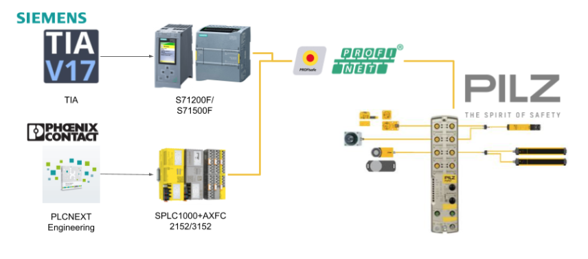
PDP67 PN 6FDI 6FDIO 2FDOTP can be combined with a Siemens TIA x S7 FCPU or a PhoenixContact SPLC1000 x AXCF 2152/3152 to set up a Profisafe F-Host for Pilz PDP67 PN 6FDI 6FDIO 2FDOTP and Profisafe communication is possible.
It is important to note that both Siemens and PhoenixContact require a separate license to use Safety.
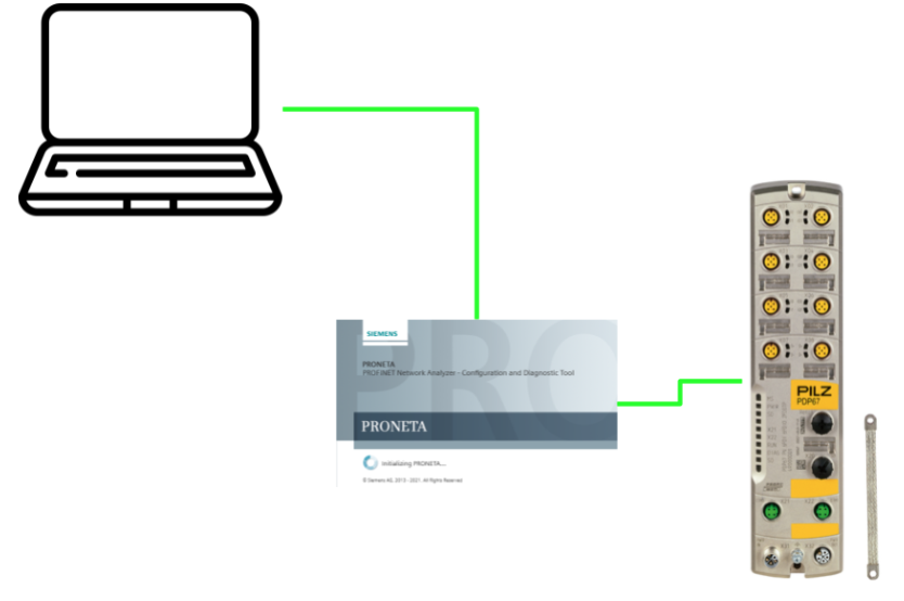
Basic Startup
Only the PC and PRONETA Basic will be used in this article.
PRONETA?
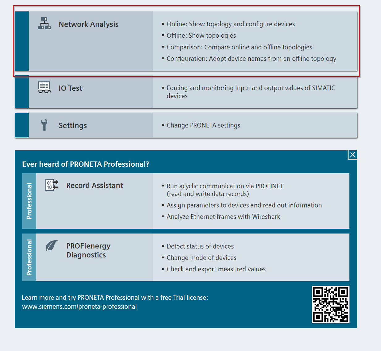
PROFINET network analyzer PRONETA Basic is a simple tool offered to analyze and configure PROFINET networks, ET 200 distributed IO systems and other components in a simple and testable way. PRONETA Basic has two main functions
- Network Analysis
- It provides an overview of the devices connected to PROFINET, sets network parameters, and assigns network names to devices belonging to the subnet to which the PRONETA PC is connected. You can also compare the project topology with the actual installation.
- IO Test
- IO Test is a function for testing IO wiring in facilities with a large number of distributed IO devices. Wiring can be checked and test procedure protocols can be automatically set up and exported as documentation.
Downlaod Tools
Download PRONETA Tools from the link below.

The ZIP file has been downloaded.
Launch Tools
Unzip the ZIP file you just created.
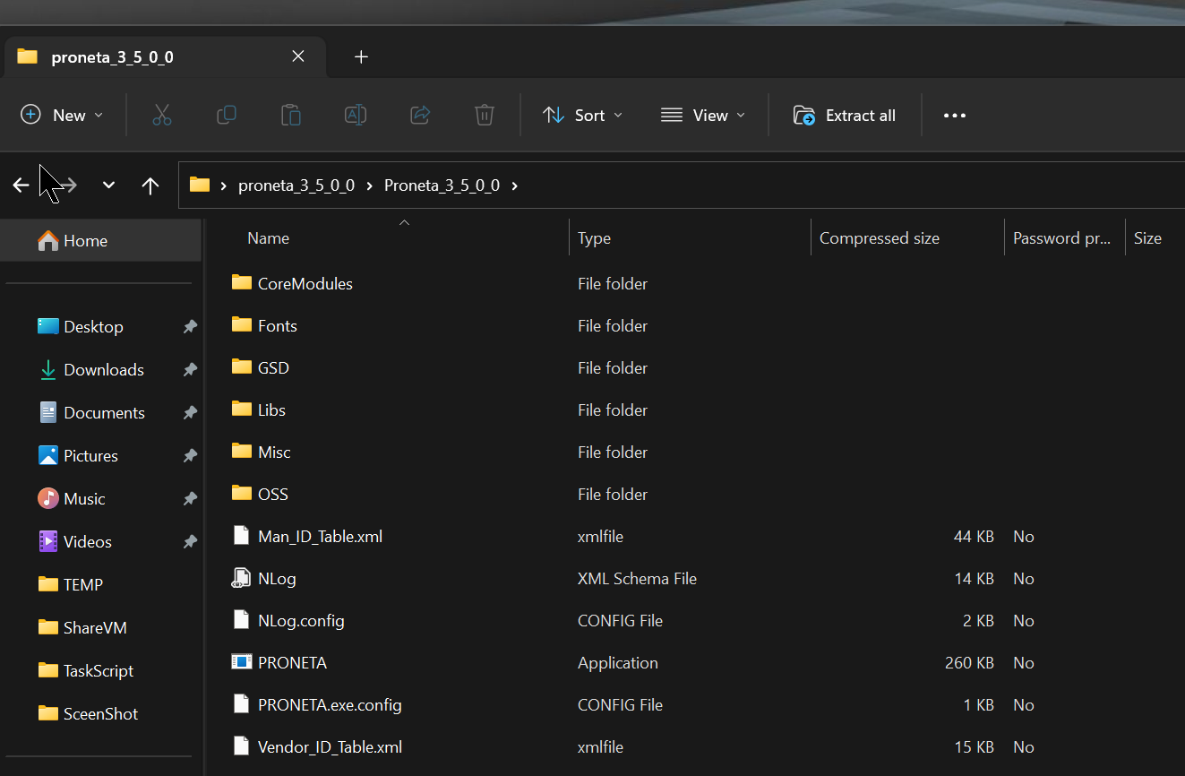
Start PRONETA.exe inside.
Agree to the license and proceed with OK.
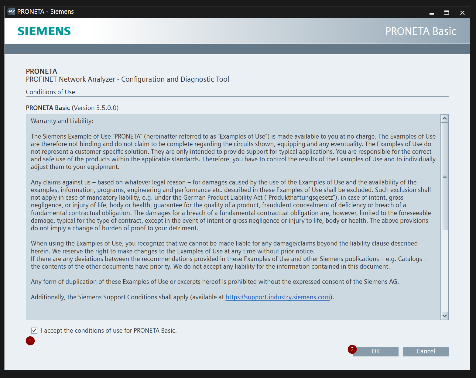
Done!This is the PRONETA Basic operation screen.

Settings
Before configuring the Pilz device, click on “Settings” to change the PRONETA settings.

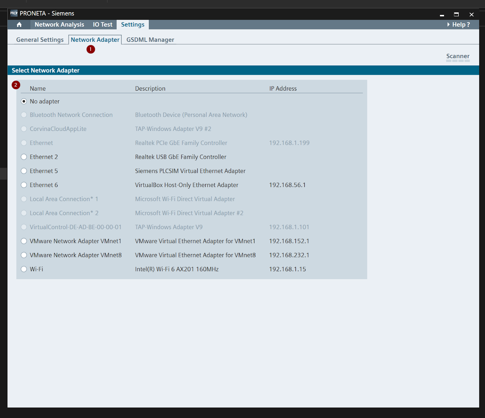
Setup Network Adapter
Open the Tab of Network Adpater and configure the Network Adapter connected to the Pilz PDP67 PN 6FDI 6FDIO 2FDOTP.
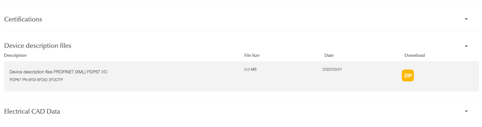
Install GSDML
Next, donwload the GSDML File for PDP67 PN 6FDI 6FDIO 2FDOTP from the following Link.
A ZIP file like this was downloaded.
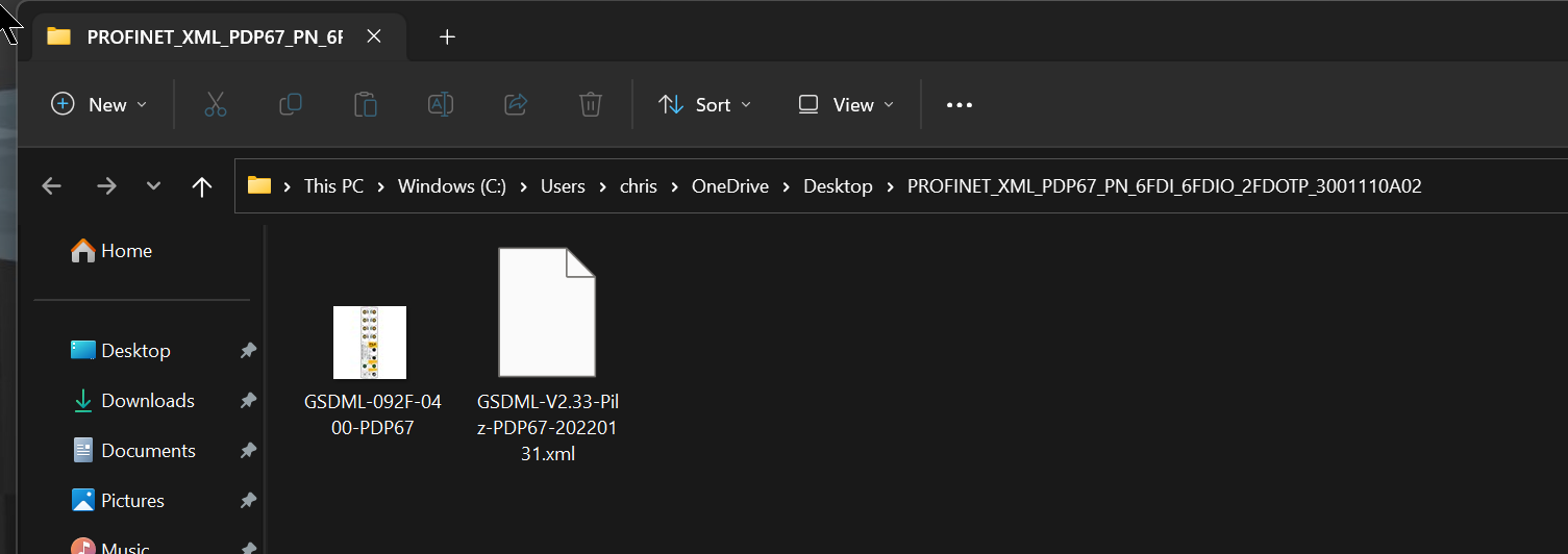
Unzip the ZIP file.
Now return to PRONETA Software and open the GSDML Manager Tab.

Click on Add GSDML File to install the GSDML File.

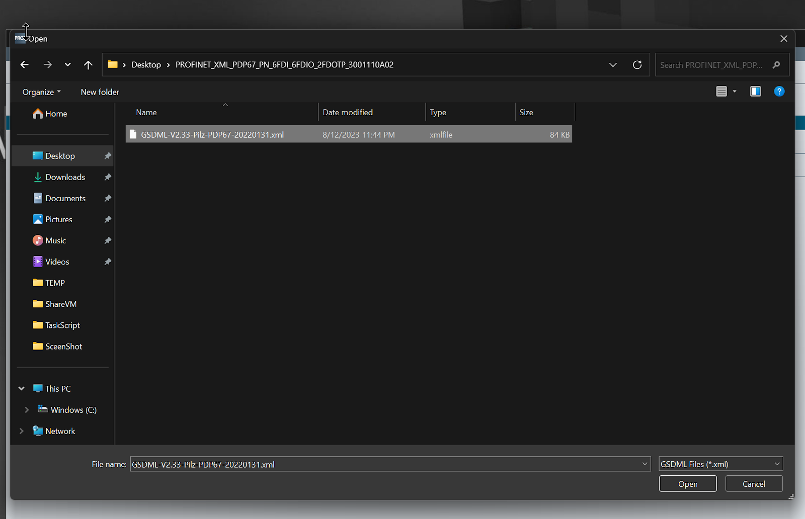
Select the XML File you just unzipped.
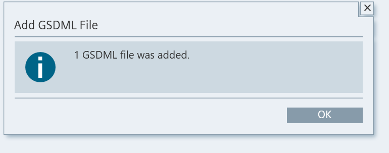
Done!GSDML File has been added.
You can see that PDP67 has been added to the Catalog of IO.

Network Analysis
PRONETA Basic’s Network Analysis is a tool that allows you to easily determine which devices are installed on your PROFINET network and how they are connected to the network.
Network Analysis feature also allows you to view and change various network parameters of the device, such as IP address and device name. It can also compare different networks against each other and configure devices automatically or manually.
Start /Stop Scanner
Right-click on “Scanner” on the far right to display the Stop Scanner button and disable/enable the auto-scan function.

Scan/Reflesh
Next, let’s scan the network with the button in the red frame.

Done!PDP67, or Pilz, the star of this article, has found a new product.
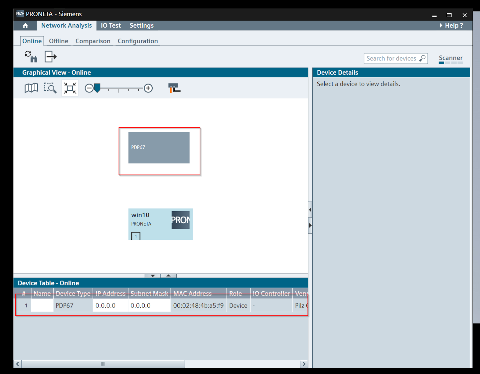
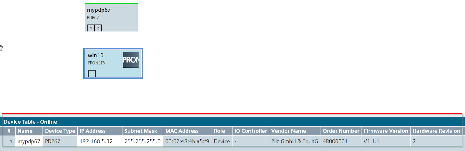
The Device Table provides information on all Profinet devices. For example,
- Device Name
- Device Type
- Device IP
- Device Subnet
- Device MAC
- Role indication such as whether the device is a Controller or Devices

Start Flashing LED
Right-click on PDP67 and use the Start Flashing LED function.
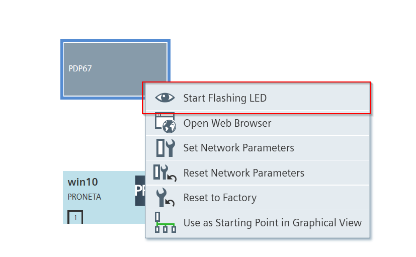
The Start Flashing LED function is enabled when the eye ICON is displayed.
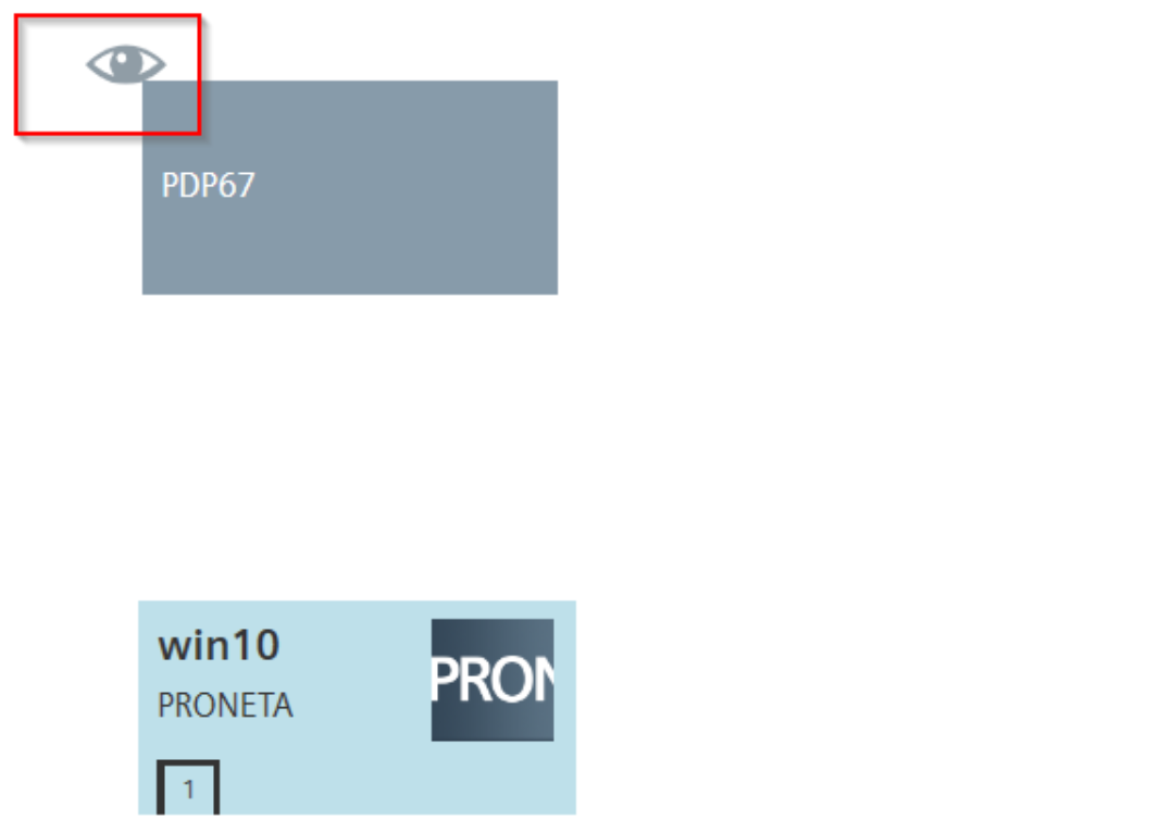
Here is the actual LED flashing from the video.
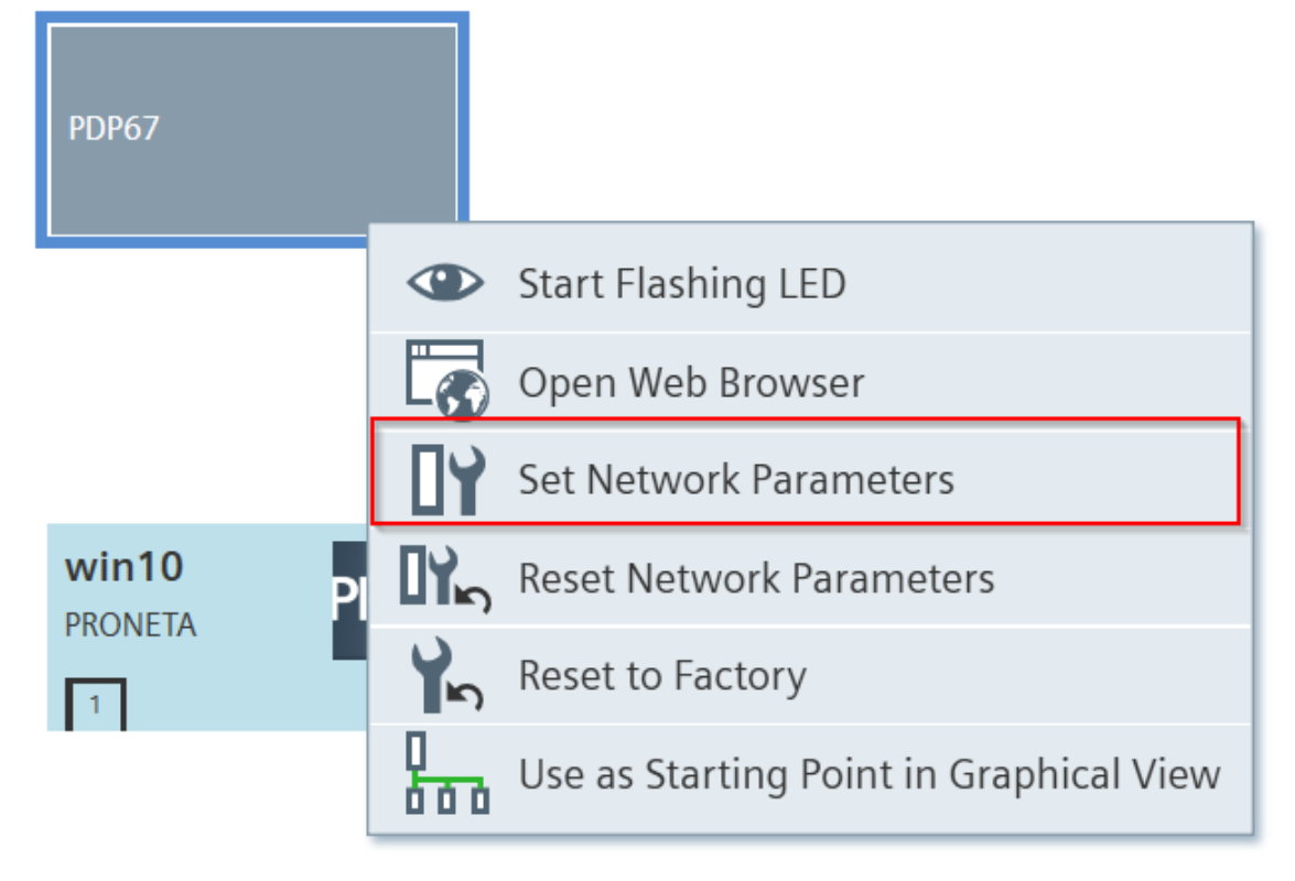
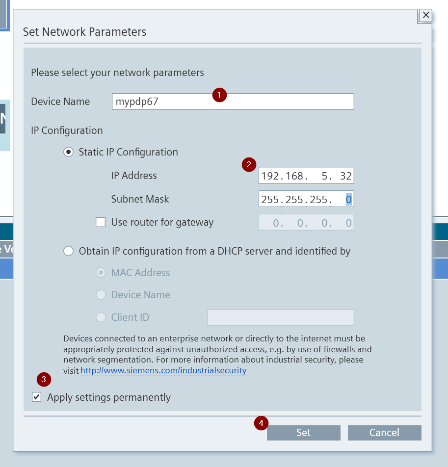
Set Network Parameters
Next, right-click on PDP67 > Set Network Parameters and set the IP and other network parameters for the corresponding device.
The Set Network Parameters screen appears.
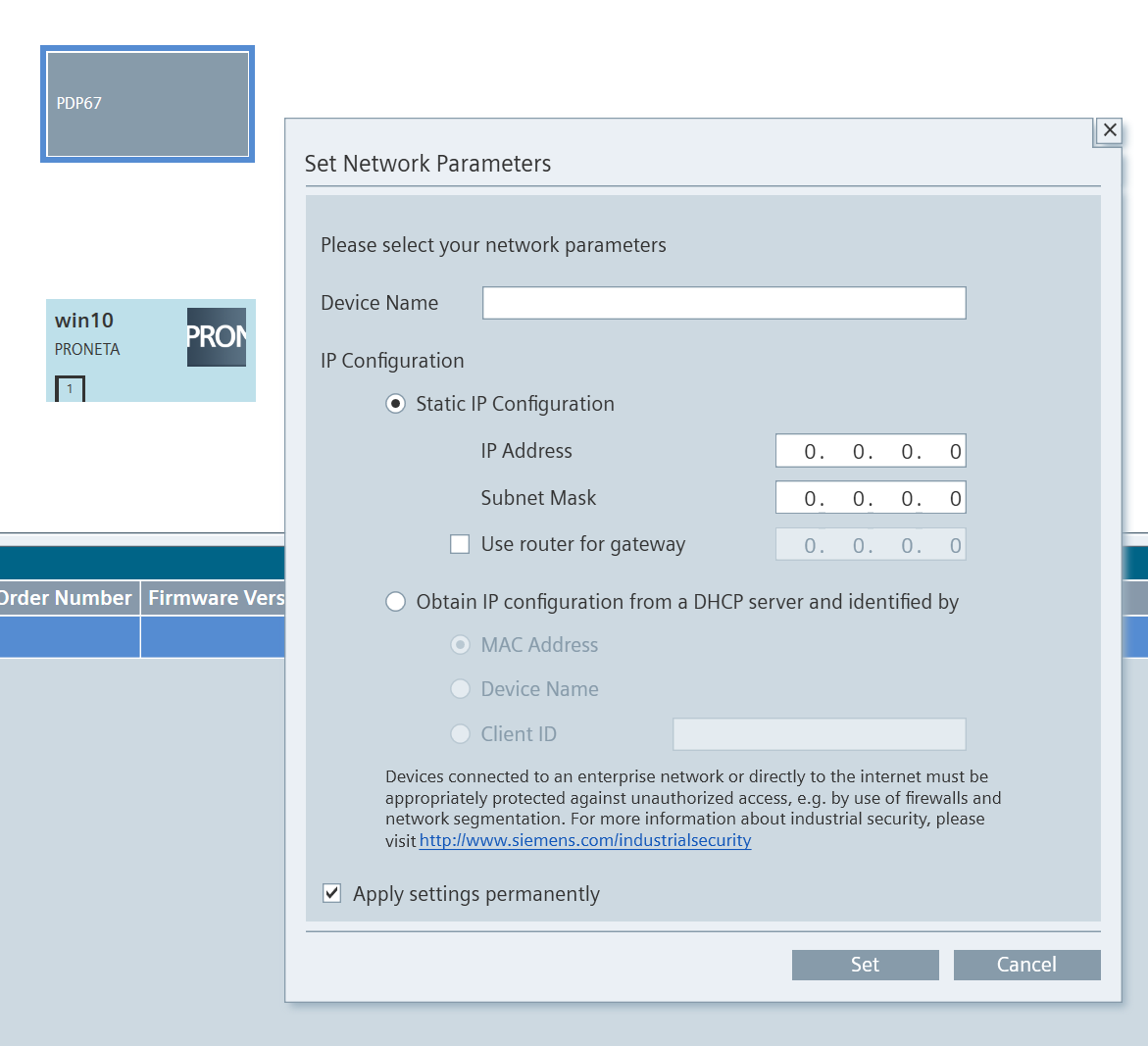
WE need to Set the Device Name and IP address for Profinet communication.
If you want to save those settings even after turning the power back on, put in the Checkbox for Apply settings permanently and finally execute them with the Set button.
Done!PDP67 PN 6FDI 6FDIO 2FDOTP network parameters have changed.
ICON also has a green line.
Open Web Browser
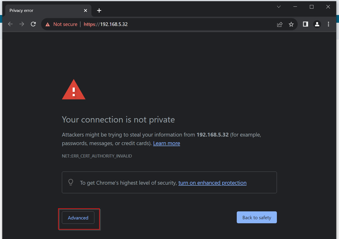
Right click on mypdp67>Open Web Brower to directly open the PDP67 PN 6FDI 6FDIO 2FDOTP Web Server.

The PDP67 PN 6FDI 6FDIO 2FDOTP Web Server is displayed from the Default Browser on the PC.

Click the Advanced button.
Click Process to 192.168.5.32(unsafe).
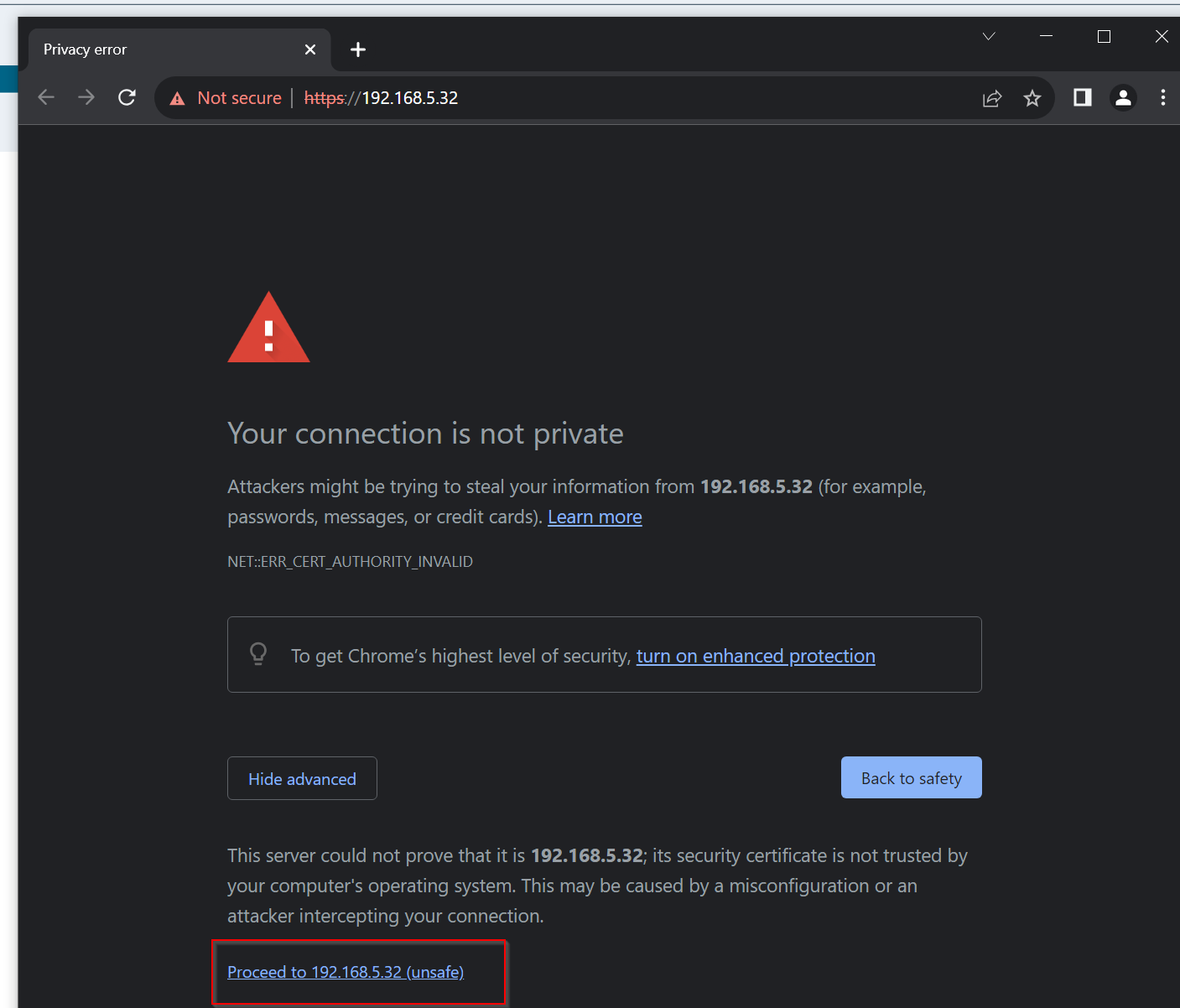
Done!Here is the web server of PDP67 PN 6FDI 6FDIO 2FDOTPのWeb Server.
By Default,
- User name:admin
- Password:PDP67
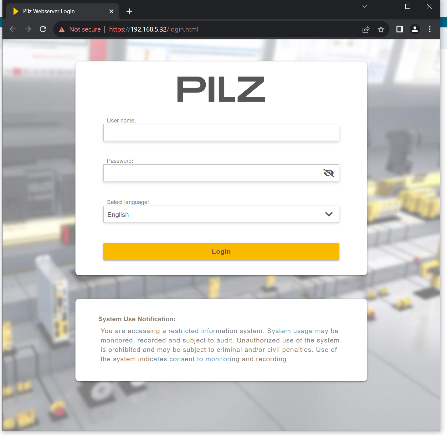
This is the Web Server screen for PDP67 PN 6FDI 6FDIO 2FDOTP. From here, you can configure and diagnose devices.
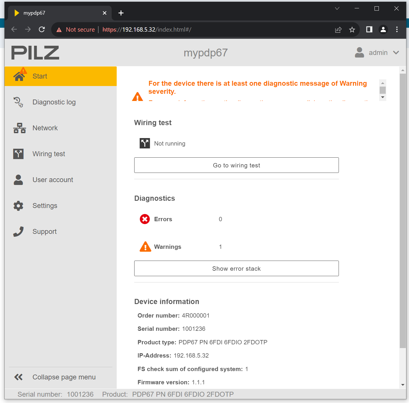
The corresponding PDP67 PN 6FDI 6FDIO 2FDOTP Profinet device name is displayed in the upper right corner.

Wiring Test
The Wiring test function is an option to verify that the device is wired correctly and can detect wiring errors. the following prerequisites are required to perform Wiring Test.
- The user is logged in as an administrator.
- Device has a valid IP address.
- The device does not have Configuration in it.
- For hybrid IO Port X02, X04, and X06, it must be verified that they are configured as inputs or outputs according to the connection diagram.
WARNING!
There are risks associated with switching outputs when performing a wiring test, and switching outputs during a wiring test can put the machine in a potentially dangerous state.
Start!
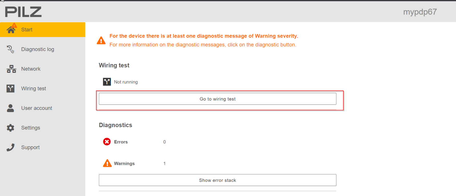
From the Start screen, click the Go to wiring test button.
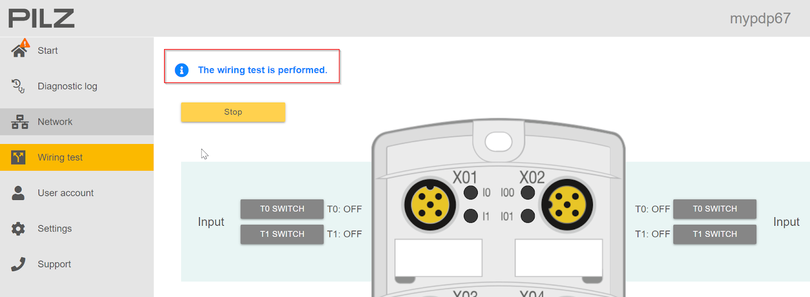
The Wiring Test screen appears. After confirming the Hybrid Ports settings and wiring of X02/X04/X06, check the Checkbox 1 and click “Start” to begin the Wiring Test.

Done!If there is no problem with the wiring, the message “The wiring test is performed” will be displayed.
Diagntosic log
Diagntosic logs can be used to check the diagnostic information history of PDP67 PN 6FDI 6FDIO 2FDOTP.

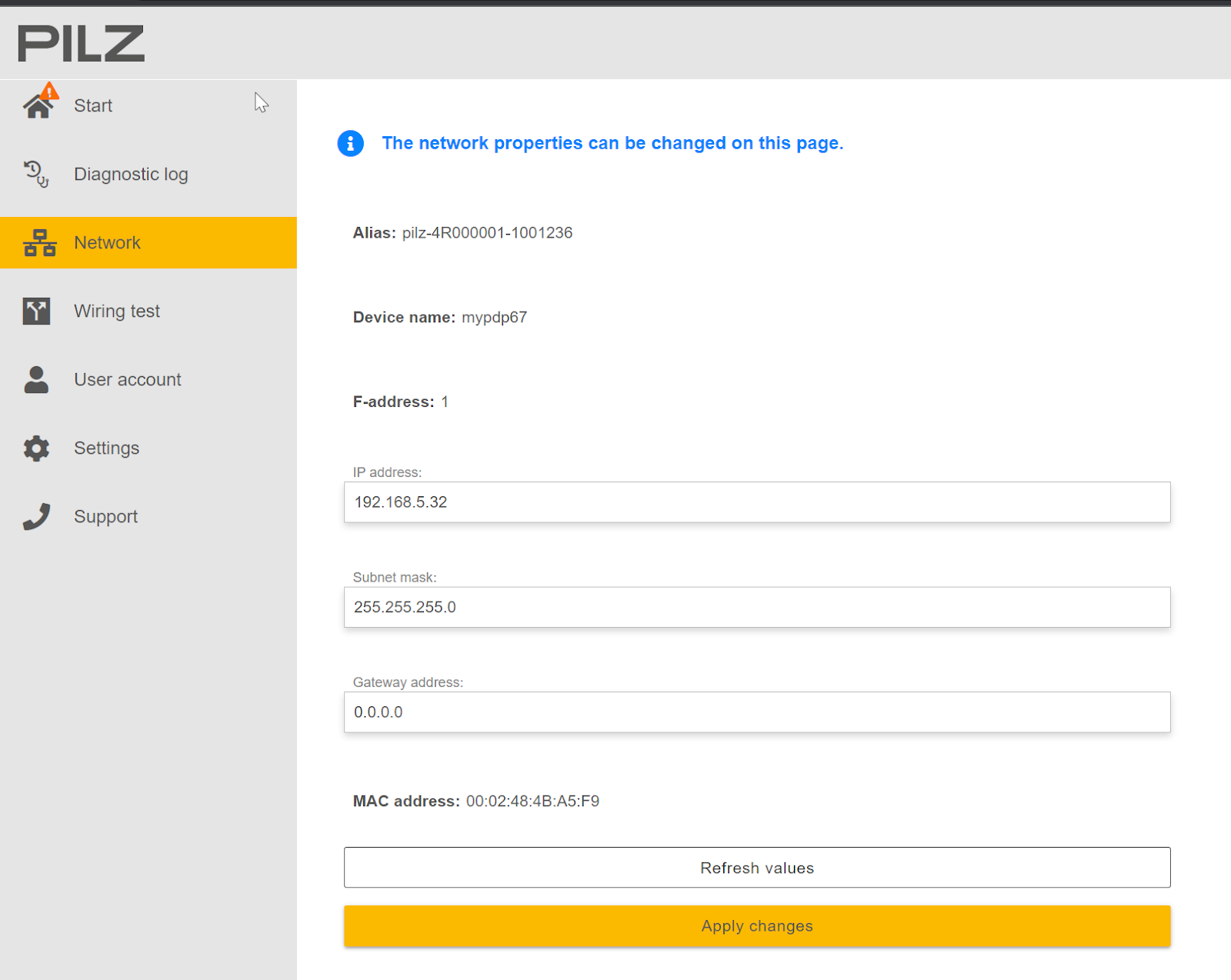
Network
Finally, from the Network Tab, you can change and check IP and other settings for PDP67 PN 6FDI 6FDIO 2FDOTP.