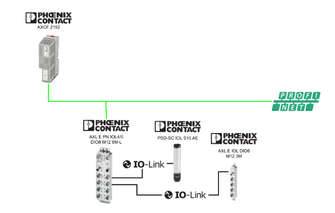
This article explains the procedure for connecting the Phoenix Contact PLCNEXT AXCF2152 and the Phoenix Contact AXL E PN IOL4/0 DIO8 M12 6M-L via Profinet. The following is the IO-Link device used in this setup:
- AXL E IOL DIO8 M12 3M
- PSD-SC IOL S15 AE
Alright, let’s enjoy the FA!
Reference Link
MEMORY_COPY
The MEMORY_COPY function used in this article copies data between data areas in the runtime system, transferring a specified number of bytes from the source data area to the destination data area.
Parameter Description
SRC
- Data type:ANY
- Description:Data area of the source
- Note:
- You can specify an array element like `MyArray[5]`
-
However, in that case, it refers to that specific element rather than the beginning of the entire array
SRC_OFF
- Data type:ANY_INT
- Description:Byte offset from the start of the source data area
- Conditions: greater than or equal to 0
DST
- Data type:ANY
- Description:Destination data area
- Note:
- You can specify `MyArray[5]`
-
However, this refers only to that specific element, not the starting position of the entire array
DST_OFF
- Data type:ANY_INT
- Description:Byte offset from the start of the destination data area
- Conditions:greater than or equal to 0
CNT
- Description:Number of bytes to copy
Output(OUT)
- Data type:UINT
- Description:Copy operation status codes
OUT Value | Description |
|---|---|
0 | Completed successfully |
1 | Invalid VAR_IN_OUT descriptor for SRC or DST (internal error) |
2 | SRC size insufficient, or SRC_OFF is invalid (CNT exceeds SRC – SRC_OFF) |
3 | DST size insufficient, or DST_OFF is invalid (CNT + DST_OFF exceeds destination size) |
12 | CNT value is out of range |
Error behavior
-
If OUT ≠ 0, an error code is returned
-
When an error occurs:
- ENO = FALSE
-
The copy operation is treated as a failure
- ENO = FALSE
How EN / ENO Works
- EN = TRUE:To execute POU
- EN = FALSE:POU is not executed, and ENO = FALSE
- Even if an error occurs during execution, ENO = FALSE
Implementation
Let’s go ahead and create a project.
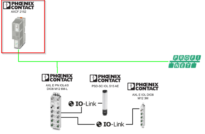
PLCNEXT Side
First, we will set up the PLCNEXT AXCF2152.
Scan the PLCNEXT controller
Click on Project ICON.
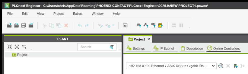
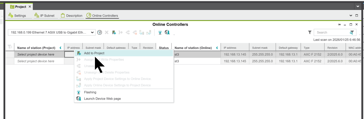
In Project → Online Controllers, click the icon below to search for devices on the network.
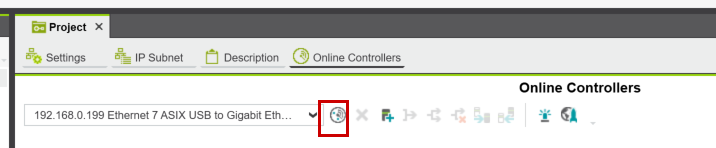
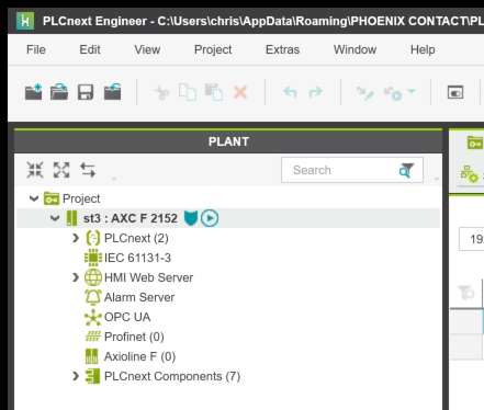
Done!I searched for AXCF 2152. Right-click on AXCF 2152 and click “Add to Project.”
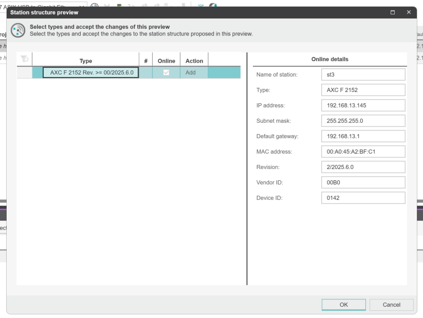
The controller selection screen will appear.
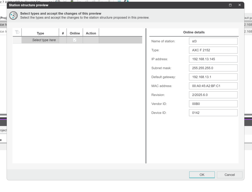
The version of AXCF 2152 used in this article is 2025.6.
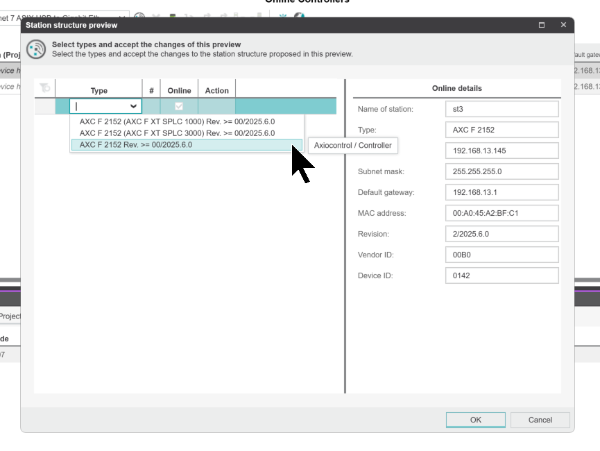
Click OK.
Enter the username and password for the AXCF 2152 unit.
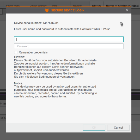
Done!
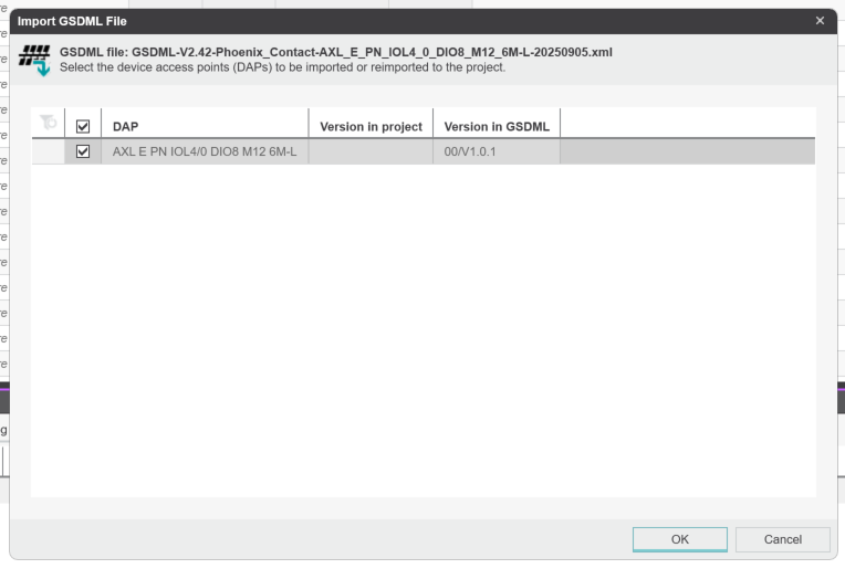
Importing GSDML
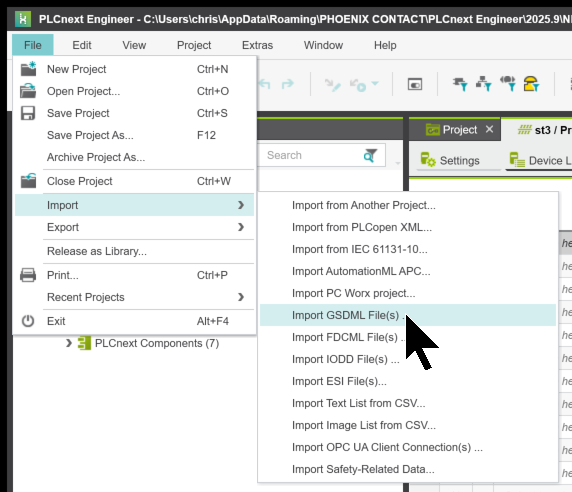
To import GSDML from the PLCNEXT Engineer tool, click File → Import → Import GSDML Files.
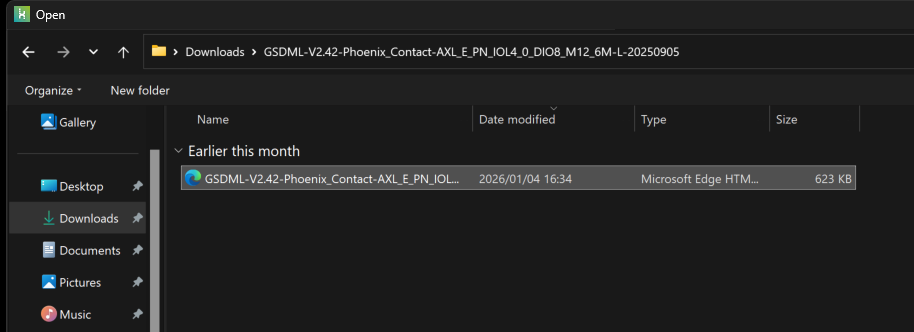
Open the GSDML file you just downloaded.
Click OK.
Profinet Network Setup
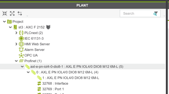
Next, to set up a Profinet network, open Project → Profinet.
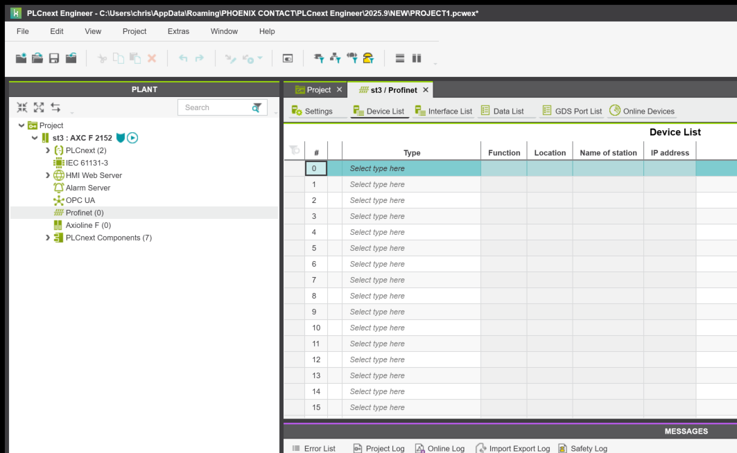
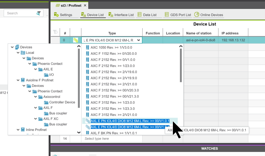
I will now insert the AXL E PN IOL4/0 DIO8 M12 6M-L used in this article.
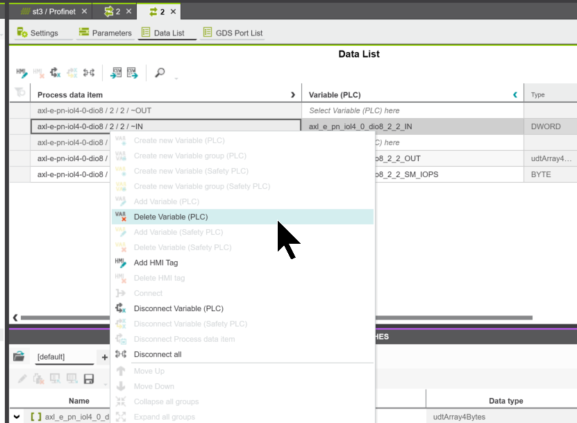
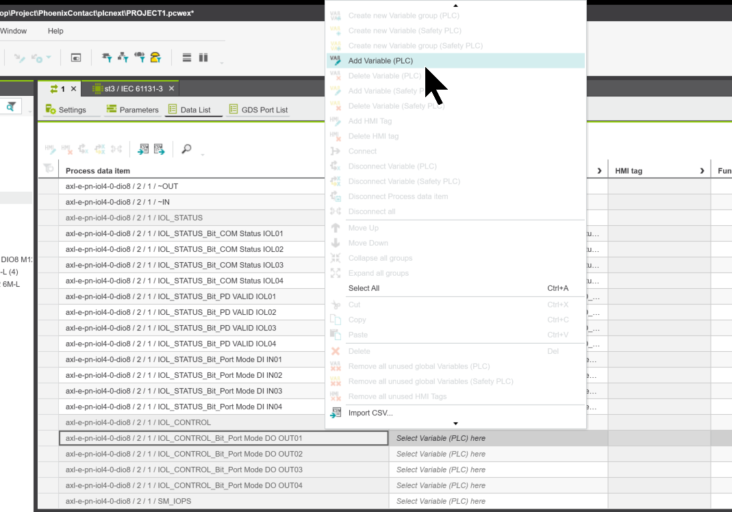
And you can Right Click->Delete Variable(PLC) to delete the variables that are not used in the project.
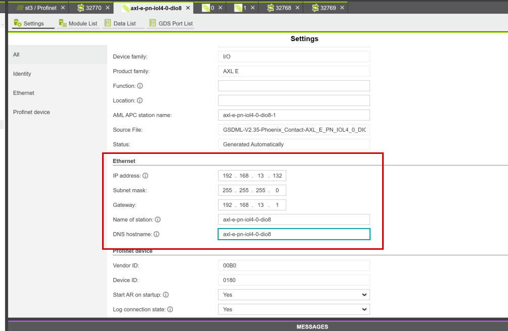
IP Address and Device Name
Next, set the device name to AXL E PN IOL4/0 DIO8 M12 6M-L.
Configure the IP address and device name for the AXL E PN IOL4/0 DIO8 M12 6M-L in the box shown below.
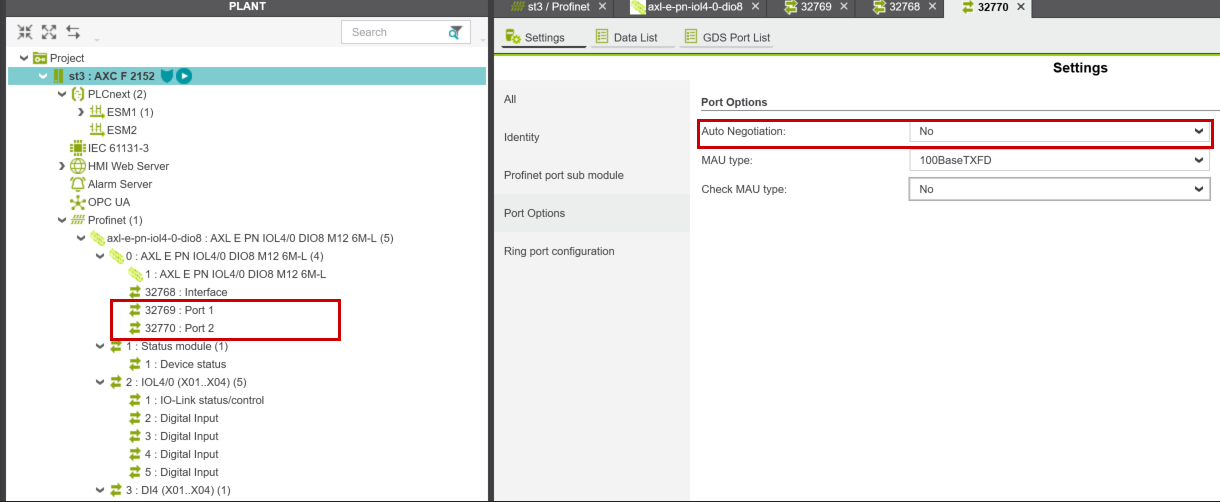
Next, set “Auto Negotiation” to NO on Port 1 and Port 2 of the AXL E PN IOL4/0 DIO8 M12 6M-L.
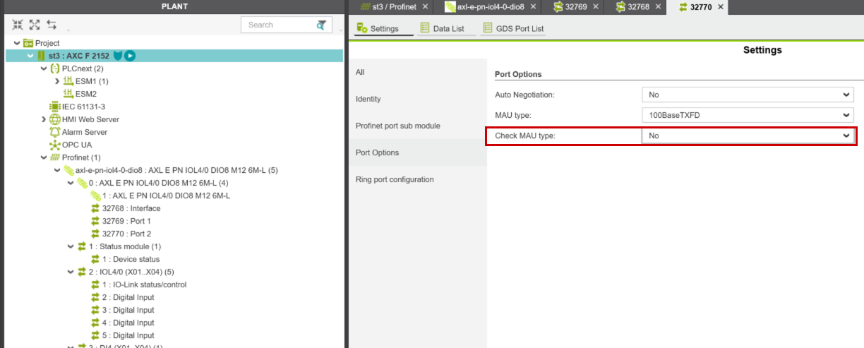
Also, since there are no Profinet devices connected to Port 2 of the AXL E PN IOL4/0 DIO8 M12 6M-L, set the “Check MAU Type” for Port 2 to “No.”
Slots
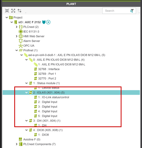
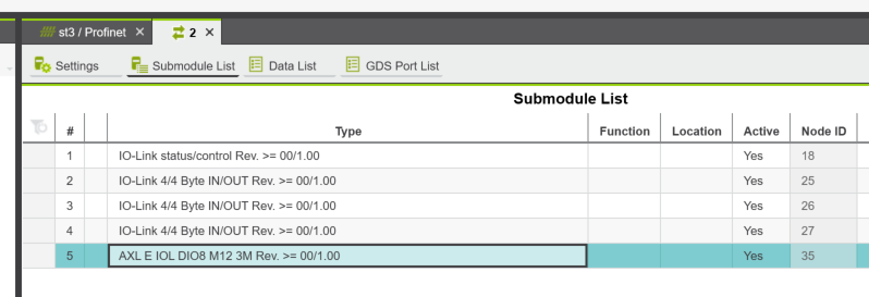
Next, we will configure the slot for the AXL E PN IOL4/0 DIO8 M12 6M-L.
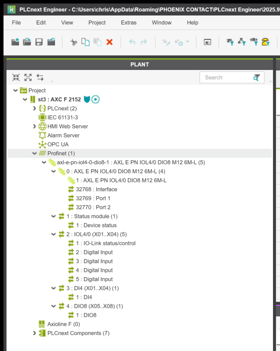
The red box in the figure below shows the current slot settings for the AXL E PN IOL4/0 DIO8 M12 6M-L. By default, Ports 1 through 4 are configured as digital inputs.
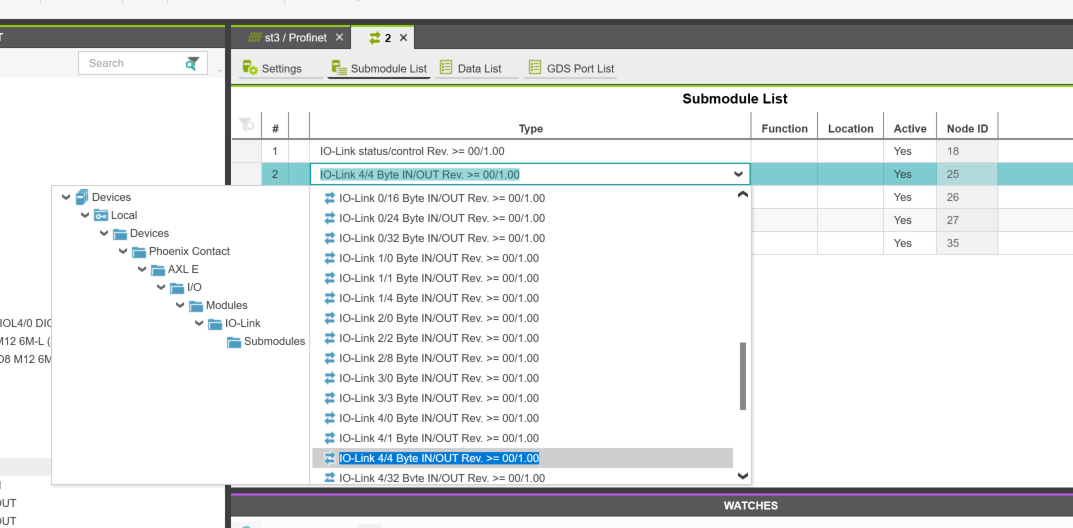
Next, we will change the settings from PLCNEXT Engineer to Slot.
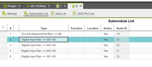
Set the number of Byte IN/OUTs according to the IO-Link devices connected to each port.
Done!Also, set the last PORT to Phoenix Contact’s AXL E IOL DIO8 M12 3M.
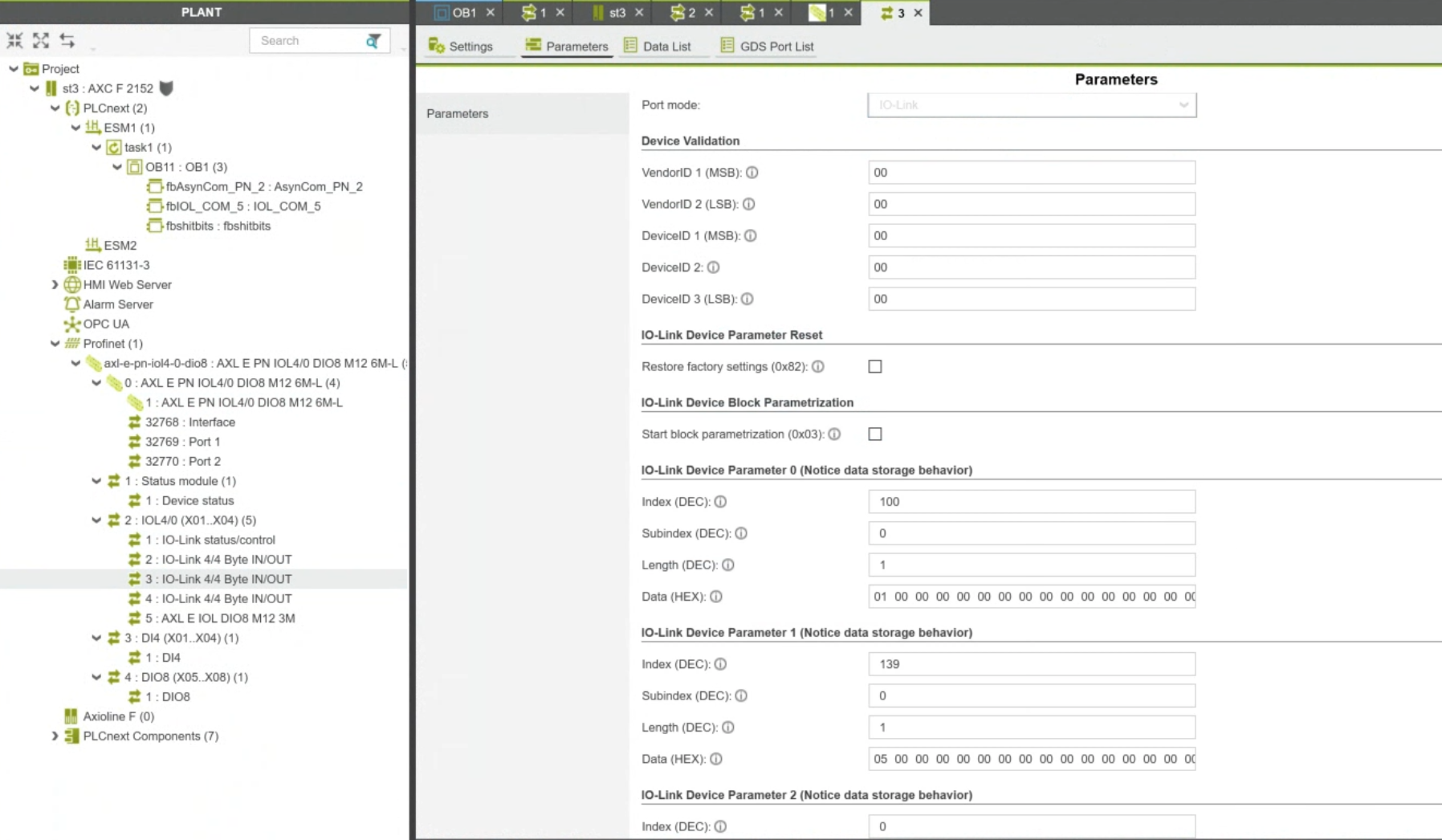
IO-Link Device Parameters
In addition, you can set individual initial parameters for the IO-Link devices connected to each IO-Link port.
DUT
Define arrays of 4 bytes, 3 bytes, and 1 byte in the project.
TYPE
|
|---|
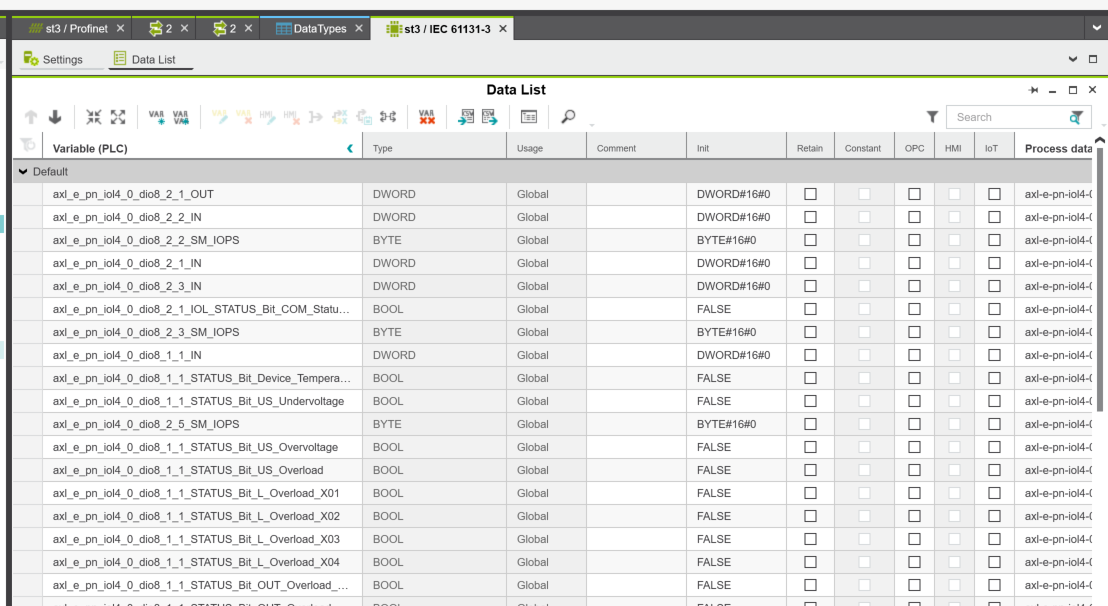
Next, to declare global variables in PLC Next Engineer, click Project → IEC 61131-3.
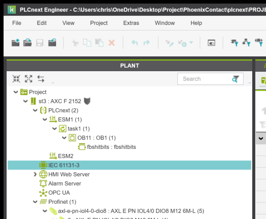
Define the variables required for the project.
To add a new variable, right-click and select “Add Variables.”
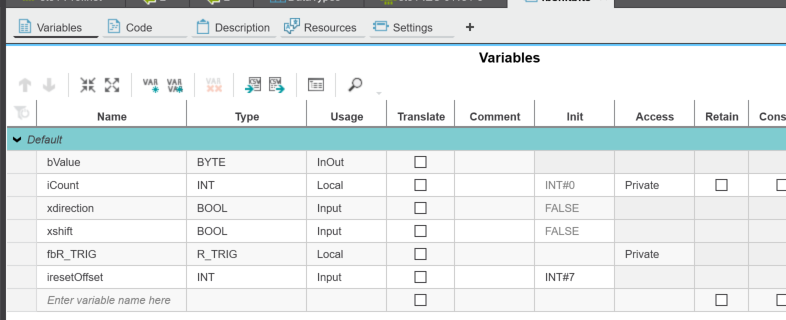
fbshitbits
This Facebook post features a program that stacks bits while shifting them left or right on the rising edge of an XSHIFT signal.
Variable | Type | Description |
|---|---|---|
xshift | BOOL | Shift execution trigger |
xdirection | BOOL | FALSE = Left shift / TRUE = Right shift |
bValue | BYTE | Bit pattern output |
iCount | INT | Shift counter |
iresetOffset | INT | Number of shifts before reset |
fbR_TRIG | R_TRIG | Rising edge detection |
Initial state: 0000_0001
1st iteration: 0000_0011
2nd iteration: 0000_0111
3rd iteration: 0000_1111
↓
Reset → 0000_0001
This is how the sequence progresses.
fbR_TRIG(CLK:=xshift);
|
|---|
MAIN
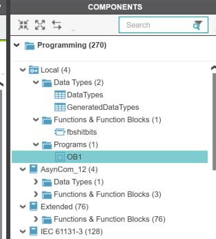
Next, to create the MAIN program, go to PLC ENGINEER → right side → COMPONENTS → Programs → Create New Program.
This program performs bit shifts at two different frequencies and outputs the results to a PROFINET device (Axioline E I/O-Link module).
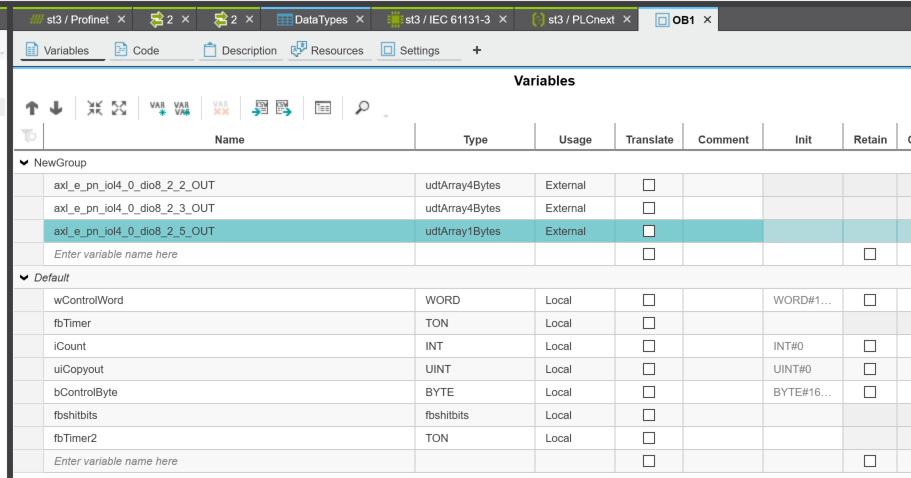
wControlWord (0.1s cycle) – flowing pattern:
0000_0000_0000_0001
0000_0000_0000_0010
0000_0000_0000_0100
↓ (1 bit shifts)
1000_0000_0000_0000
↓ reset
0000_0000_0000_0001
bControlByte (1s cycle) – accumulating pattern:
0000_0001
0000_0011
0000_0111
0000_1111
↓ reset (upon reaching 4 shifts)
0000_0001
fbTimer(in:=not fbTimer.Q,PT:=T#0.1s);
|
|---|
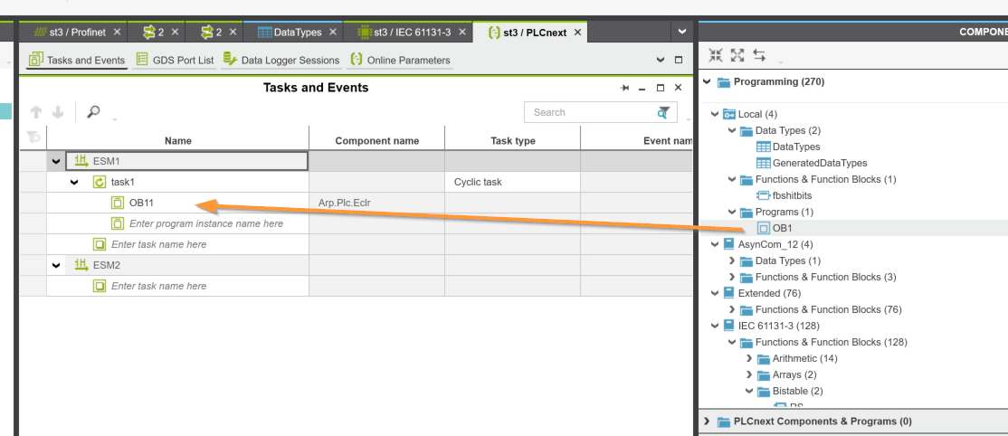
Add a program to a task
Next, let’s configure the program to run in Runtime. Click PLCnext here.
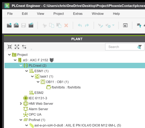
Let’s add the program we just added to the Task.
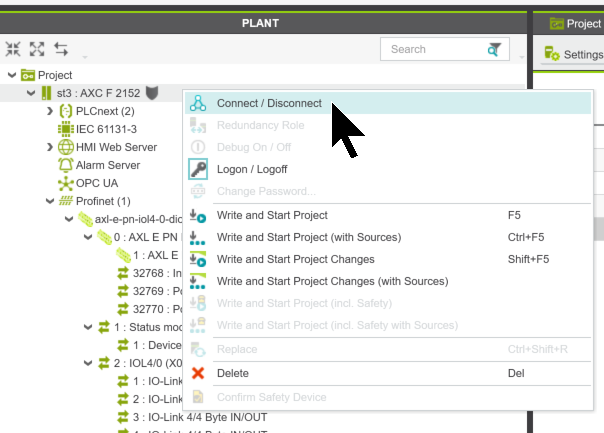
Connection
To connect to the PLC ENGINEER and AXF2152, select the PLC, right-click, and choose “Connect/Disconnect.”
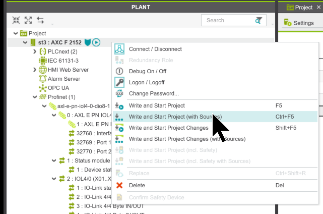
Download
Next, click “Write and start Project (With sources)” to download the program to the AXF2152.
Results
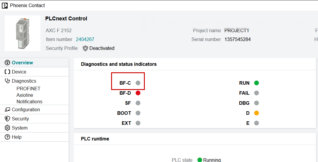
To check the Profinet communication status of the AXF2152, access the AXF2152 Web Server and open the “Overview” page. As shown in the figure below, communication is OK as long as BF-C is not red.
You can also check the PROFINET communication status from Diagnostics → PROFINET → TREE VIEW.
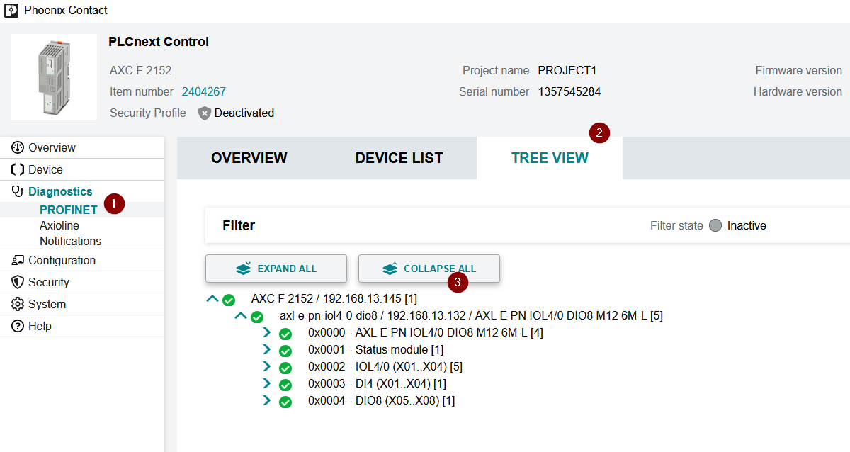
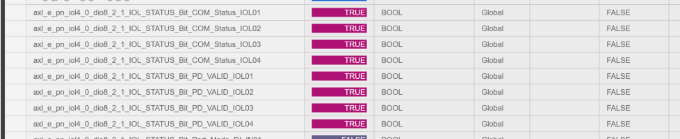
The communication status for each port is also normal.
You can see how it works in this video.
https://youtube.com/shorts/VYD2tp0OLcc
Project Download
Please download the project for this article from this link.
https://github.com/soup01Threes/PLCNEXT/blob/main/PROJECT_IOLINK_BasicConfiguration.pcweax