In the last tutorial, we used a Profinet IO-LINK Master to connect with Codesys, Ethernet/IP IO-LINK master is used in this tutorial and connected with Beckhoff TwinCAT3 TF6281.
Configuration
Here is the configuration, and TwinCAT3 TF6281 is used here to startup a Ethernet/IP Scanner and connect to the Ethernet/IP IO-Link Master TCIEI-888P-DYU from Molex.
And Also,TwinCAT3 Ethernet/IP API is used to send the Explicit message to the target.
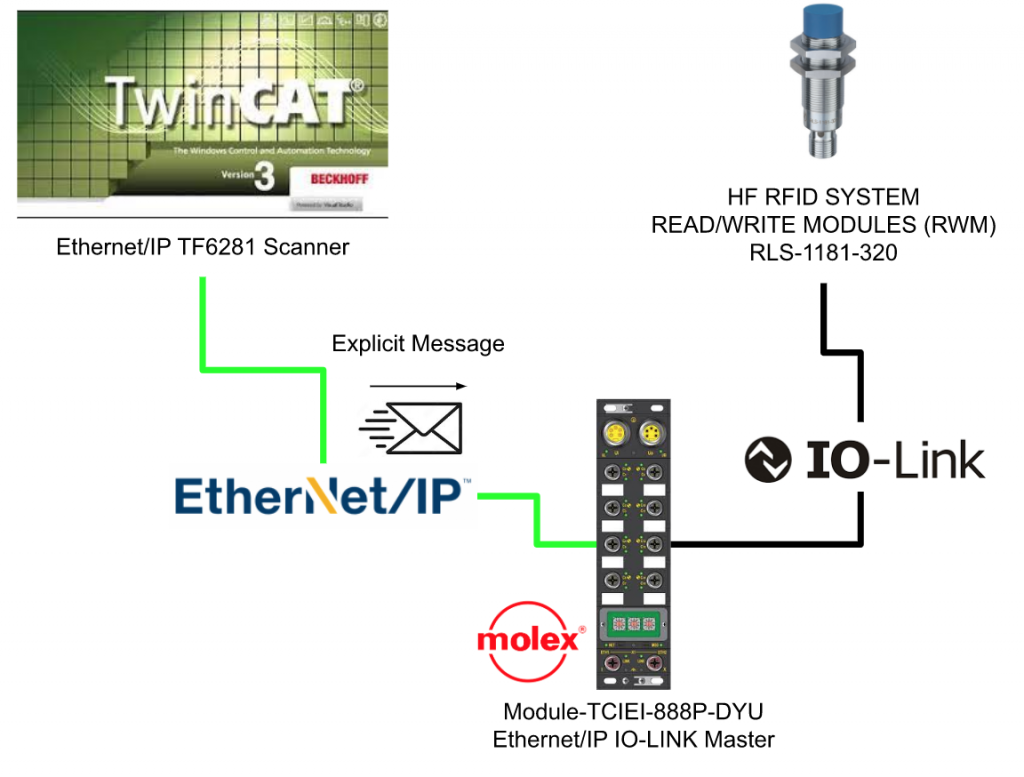
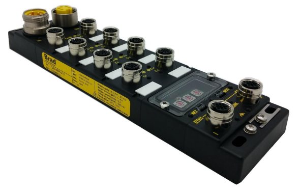
Module-TCIEI-888P-DYU
This is the module that we are using in this tutorial. It is a IO-LINK Master with Ethernet/IP Adapter Interface, Come from Molex(TCIEI-888P-DYU)
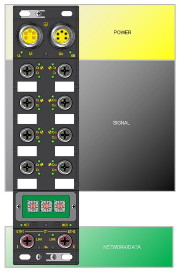
Signal Map
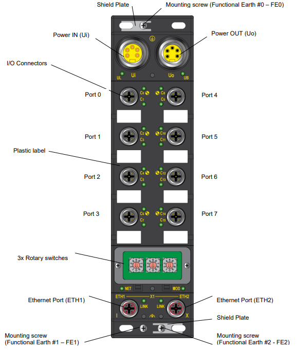
This module is separated into 3 parts – Power,Signal and Network.
Overview
Wiring
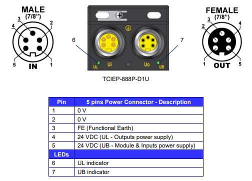
Ui/Uo
Here is the wiring.
LED
Basic Information
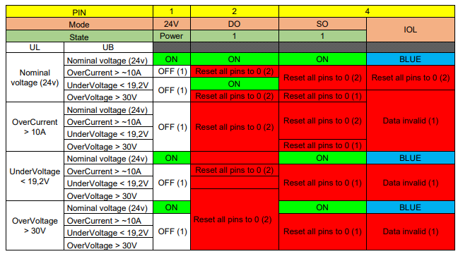
Here is the information of the LED and mainly you see green/red or blue while operating the device.Red is Alarm, Green is Normal and Blue is the status of IO-Link connection.
I/O Port
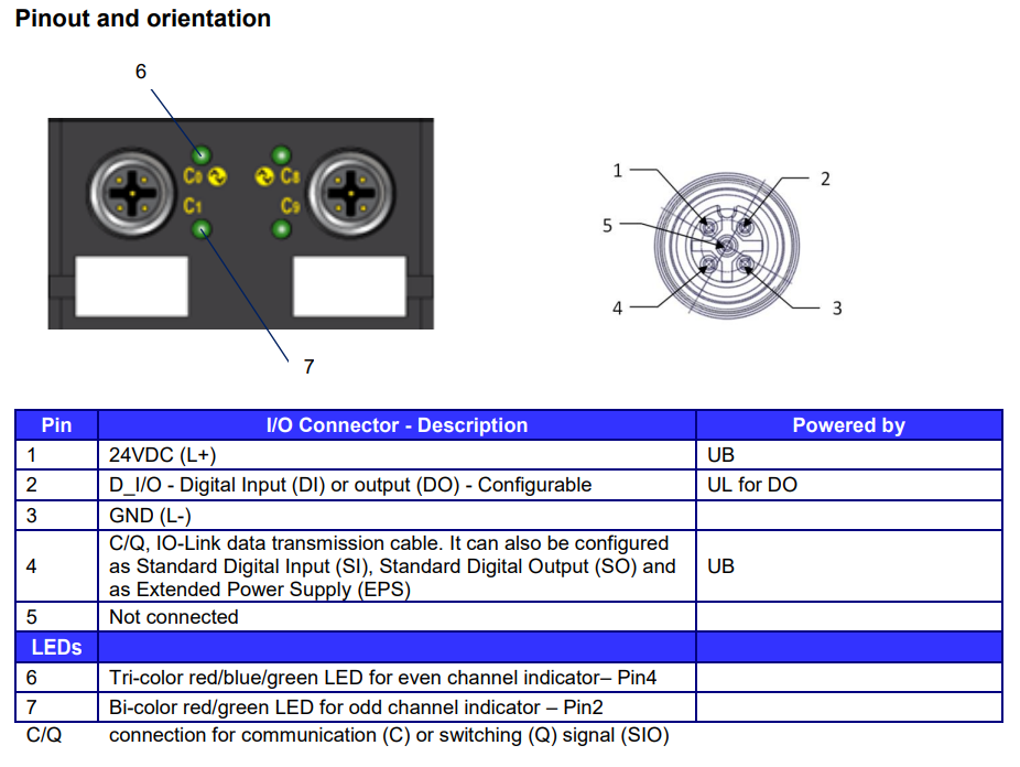
Here is the wiring of each port.
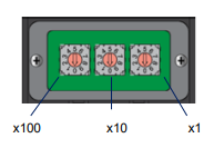
IP setting
You can set the IP by using the rotary switch. The default range of ip is 192.168.1.0/24. The last digital is defined by the Rotary switch.
For example the IP will be 192.168.1.1.153 if you set the x100=1,x10=5 and x1=3.
IO Connections
Here is the max of IO Connection.
Exclusive Ownerx1,Total x7 of Listen only and input only.

Data map
Here is the data mapping, you can choose to use I/O and status/IO-LINK,depending on your application.

Assmbly #113
In this tutorial, we will use Assembly#113.

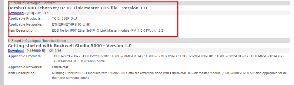
Download EDS
Although an EDS file is not a must in the Ethernet/IP Communication, it can decrease your mistake while configuring the adapter.
Please import the EDS file and use it if your engineering tool is supported.
TwinCAT
Now we can configure the TwinCAT3 Side.Function TF6281 is used in the project to startup an Ethernet/IP Scanner, and connect with TCIEI-888P-DYU Ethernet/IP IO-LINK Master, made by molex.
Reference Link
Point1- Scanner IP Setting
It is very easy to forget to set the virtual IP for the TwinCAT3 Ethernet/IP Scanner.If default 0.0.0.0 is used, you can not connect to the adapter.
Go to Scanner>Settings>F800.0>F800.21 and F800.22 to set the IP and subnet.

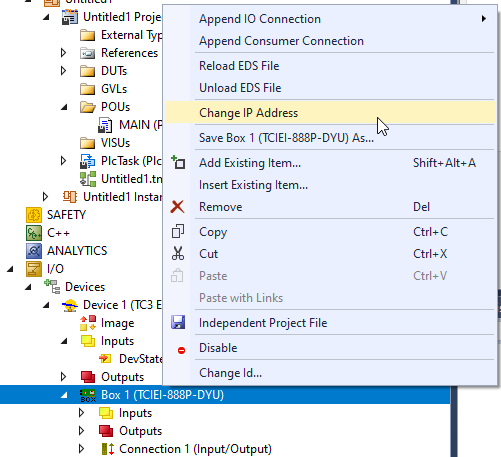
Point2-Adapter IP Setting
Right click your Box(Adapter) and select “Change IP Address” to modify the ip address of the adapter.
Point3-Network Adapter Setting
Do not forget to setup the network card that is connected to your network.
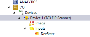
Go to TC3 EIP Scanner>Adapter>Search.
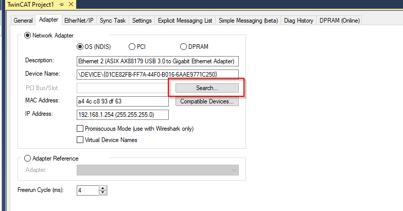
Choose your network interface.

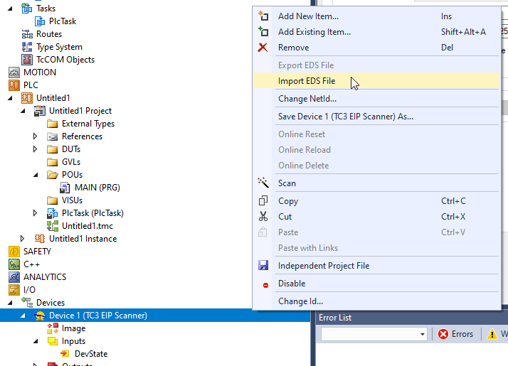
Point4-Import EDS File
You can import the EDS file by just right clicking your TC3 EIP SCanner>Import EDS File .
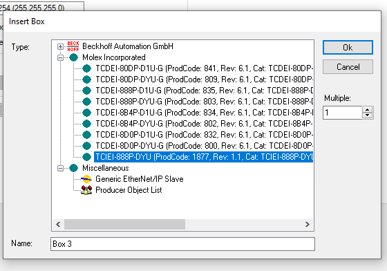
Point5-Select the Right Device
Please make sure the device that you inserted is correctly.
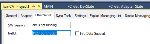
Point6-Scanner AmsNetID
This AmsNetID is used while you want to send an explicit message in the CIP network.

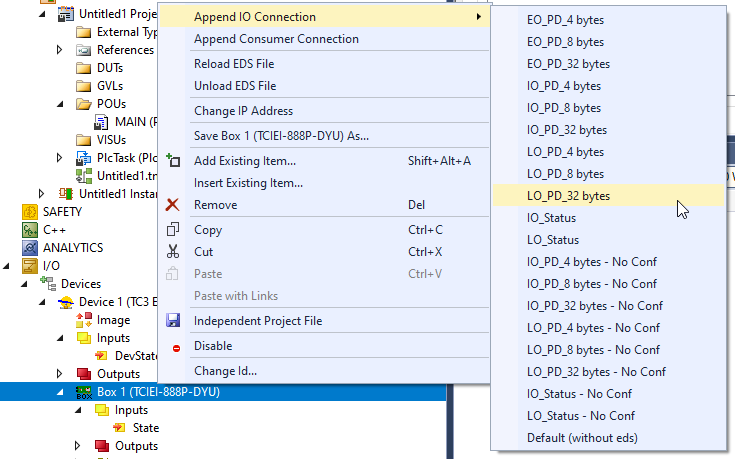
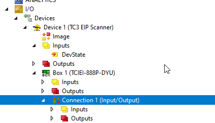
Append IO Connection
Insert the IO Connection by Right Click Box1>Append IO Connection>LO_PD_32bytes.
This IO Connection is Assembly #113.
Configuration
Now we can configure the Module.As the last tutorial, IO-LINK master can set the function of each port to be IO-LINK port or just DI/DO.
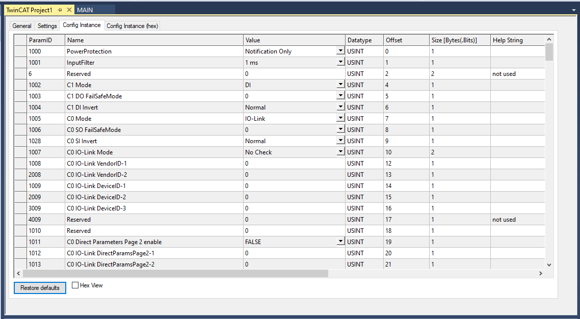
Double Click the connection that you inserted before.
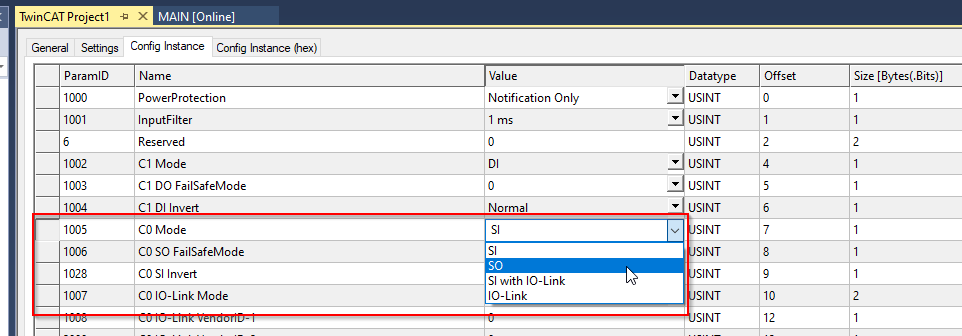
Open the Config Instance Tab,you can configure each port.
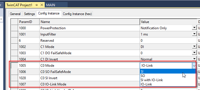
Example1-Configure port0 as DI
In this Example we will set the Port 0 as Digital Input.
Go to C0 Mode>Value and Choose SI.
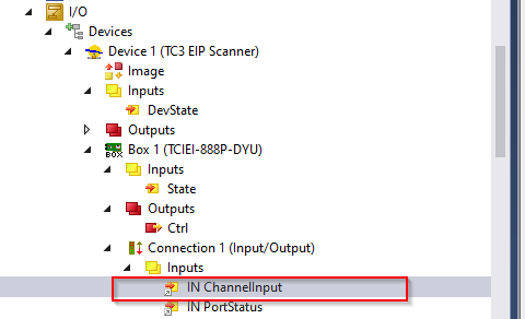
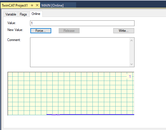
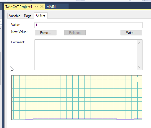
Click the IN ChannelInput.
The value will be changed to 1 if the ESTOP is released.
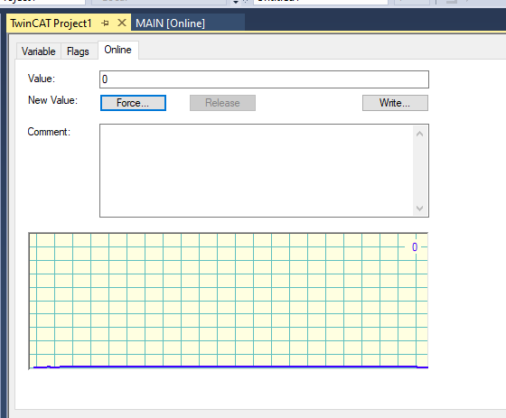
The value will be changed to 0 if the ESTOP is pressed.
Example2-Configurare Other port as Input
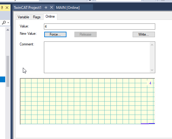
In this Example we will change other ports to see the difference of IN ChannelInput.
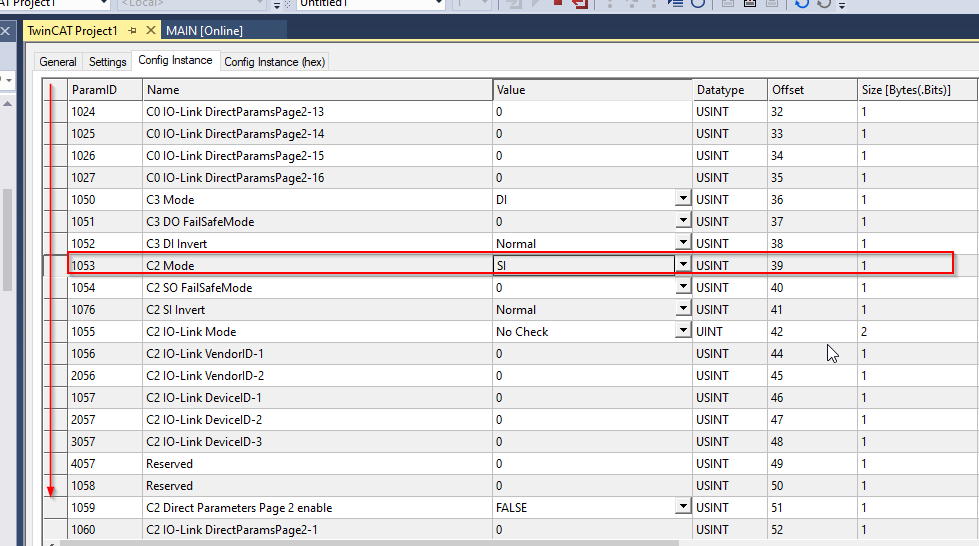
Select C2 Mode and change the setting to SI.
Click the IN ChannelInput.
The Value will change to 4 while a High signal is input into port2.
It means that all input values will be grouped as a value, and Bit0=port0, Bit1=Port1..etc.
Example3-Configure port0 as DO
In this example we try to configure the Port0 as Digital Output.
Open the Box1>Connection1>Outputs>OUT DATA CHANNEL.

Write value1 into the OUT DATA CHANNEL, port 1 will output a high signal.
Example4-Configure port0 as IO-LINK
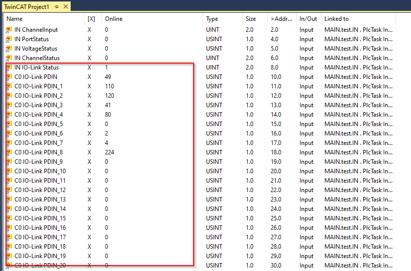
Finally we will set port0 as IO-LINK Mode.

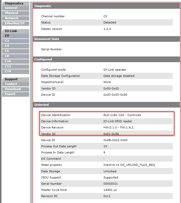
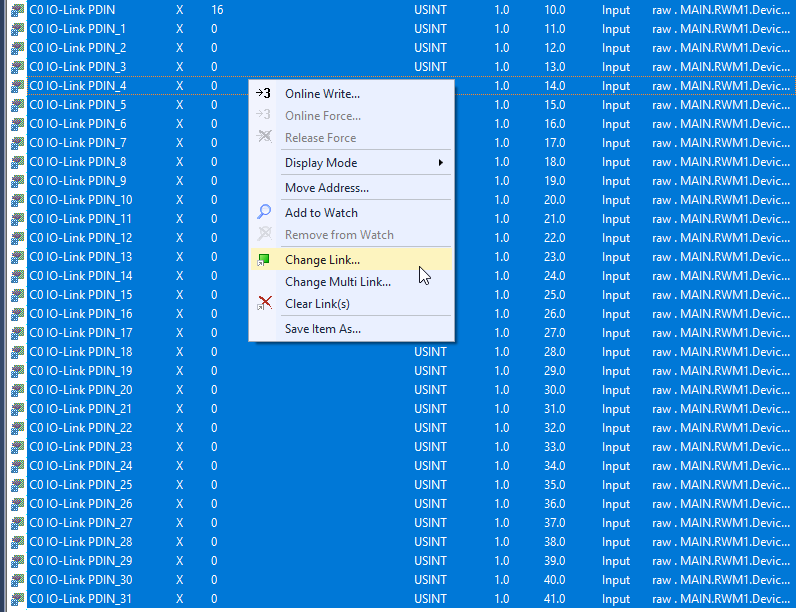
We can check all IO-LINK data of Port0 in C0 IO-Link PDIN.. variables.

The value that is read from RFID is shown.
Open your Browser, and input the IP of your Molex Device,
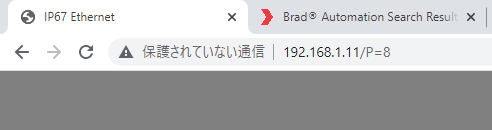
you can check the status of each port.

And also you can get all IO-LINK information in the C0 tab.
Program
Reference Link
The program is very similar to my last tutorial – because the io-link device is not changed ,only the fieldbus is different.
Bouns: Explict Messages
Here is a small bonus 😉 I will you how to use Beckhoff TwinCAT3 API to send the Explicit message to the adapter.
FB_GET_ATTRIBUTE_SINGLE
We can use this function block to send an explicit message with services GET_Attribute_Single.

VAR_INPUT
| Name | Type | Description |
| sNetId | T_AmsNetID | TwinCAT EtherNet/Ip Scanner AMSNetId |
| sIPv4Addr | T_IPv4Addr | Target IP |
| bExecute | BOOL | Start with a rise edge |
| nClass | WORD | CIP Class number |
| nInstance | WORD | CIP Service Instance number |
| nAttribute | WORD | CIP Service Attribute number |
| pDst | POINTER TO BYTE | Pointer of the destination.Get it by using ADR() |
| nMaxLen | WORD | .Memory length of the destination.Get it by using SIZEOF() |
| nSessionTimeoutMSec | DWORD | Session Timeout、Default=30s |
| nCmdTimeoutMSec | DWORD | Command Timeout,Default=7.5s |
| bRackComm | BOOL | Ture if CompactLogix is used |
| nPort | BYTE | CPU Port Number(Only 1 is supported in TF6281) |
| nSlot | BYTE | Slot number |
VAR_OUTPUT
| bBusy | BOOL | True=executing, and go to False again if Feedback is received. |
| bError | BOOL | True=Error |
| nErrId | UDINT | Error infomration |
| nDataLen | WORD | Data length that received from Target(Bytes) |
FB_CUSTOM_SERVICE
We can use this function block to send a custom service message.

VAR_INPUT
| Name | Type | Description |
| sNetId | T_AmsNetID | TwinCAT EtherNet/Ip Scanner AMSNetId |
| sIPv4Addr | T_IPv4Addr | Target IP |
| bExecute | BOOL | Start with a rise edge |
| nServiceCode | BYTE | CIP Service Code |
| nClass | WORD | CIP Class number |
| nInstance | WORD | CIP Service Instance number |
| nAttribute | WORD | CIP Service Attribute number |
| pDst | POINTER TO BYTE | Pointer of the destination.Get it by using ADR() |
| nMaxLen | WORD | .Memory length of the destination.Get it by using SIZEOF() |
| nSessionTimeoutMSec | DWORD | Session Timeout、Default=30s |
| nCmdTimeoutMSec | DWORD | Command Timeout,Default=7.5s |
| bRackComm | BOOL | Ture if CompactLogix is used |
| nPort | BYTE | CPU Port Number(Only 1 is suported in TF6281) |
| nSlot | BYTE | Slot number |
VAR_OUTPUT
| bBusy | BOOL | True=executing, and go to False again if Feedback is received. |
| bError | BOOL | True=Error |
| nErrId | UDINT | Error infomration |
| nDataLen | WORD | Data length that received from Target(Bytes) |
Implemention
DUT
DUT_EIP_Object01
This DUT is defined with CIP Object 01 Structure.
| TYPE DUT_EIP_Object01 : STRUCT VendorID :UINT; DeviceType :UINT; ProductCode :UINT; Revision_Major :USINT; Revision_Minor :USINT; Status :UINT; SerialNumber :UINT; ProductName :STRING(31); State :UINT; ConfigurationConsistencyValue :UINT; HeatbeatInterval:UINT; END_STRUCT END_TYPE |
DUT_EIP_Adapter_State
This DUT is defined with TwinCAT3 Adapter Status.
| TYPE DUT_EIP_Adapter_State : STRUCT RemoteNodeNoConnection :BOOL; RemoteNodeNotReachable :BOOL; TCPClientInitFailed :BOOL; UDPClientInitFailed :BOOL; ConnectionDisconnected :ARRAY[1..8]OF BOOL; END_STRUCT END_TYPE |
DUT_EIP_DevState
This DUT is defined with TwinCAT3 Ethernet/IP Status.
| TYPE DUT_EIP_DevState : STRUCT LinkError :BOOL; IOResetRequired :BOOL; WatchdogTriggered :BOOL; MasterNoValidIP :BOOL; TCPServerUnable :BOOL; UDPServerUnable :BOOL; Normal :BOOL; Error :BOOL; END_STRUCT END_TYPE |
DUT_Contrinex_RLS_1181_320
Contrinex RFID Reader is used in this tutorial.(Please reference with my last tutorial )
| TYPE DUT_Contrinex_RLS_1181_320 : STRUCT Status :DUT_Contrinex_RLS_1181_320_Byte0Status; UID_LSB :DINT; UID_MSB :DINT; _ :ARRAY[0..6]OF BYTE; END_STRUCT END_TYPE |
DUT_Contrinex_RLS_1181_320_Byte0Status
Please reference my last tutorial with memory mapping.
| TYPE DUT_Contrinex_RLS_1181_320_Byte0Status : STRUCT b00NBTag :BIT; //Number of Tags in front of RWM b01NBTag :BIT; //Number of Tags in front of RWM b02NBTag :BIT; //Number of Tags in front of RWM b03NBTag :BIT; //Number of Tags in front of RWM b04ANT :BIT; //0=RF Field OFF b05TAG :BIT; //0=No tag present in front of RWM b06,b07 :BIT; END_STRUCT END_TYPE |
uDUT_Contrinex_RLS_1181_320
Please reference my last tutorial with memory mapping.
| TYPE uDUT_Contrinex_RLS_1181_320 : UNION raw:ARRAY[0..31]OF BYTE; Data:DUT_Contrinex_RLS_1181_320; END_UNION END_TYPE |
Function Block
FB_Contrinex_RLS_1181_320
This Function block is similar to my last tutorial and I will not explain too much.
VAR
| FUNCTION_BLOCK FB_Contrinex_RLS_1181_320 VAR_INPUT END_VAR VAR_OUTPUT UIDLSB :DINT; UIDMSB :DINT; UID :LINT; TagsInfrontOFRWM :BYTE; TagOnRWM :BOOL; RFFieldON :BOOL; END_VAR VAR Device AT%I* :uDUT_Contrinex_RLS_1181_320; END_VAR |
PROGRAM
| UIDLSB:=Device.Data.UID_LSB; UIDMSB:=Device.Data.UID_MSB; UID:=SHL(DINT_TO_LINT(Device.Data.UID_MSB),32); UID:=UID+Device.Data.UID_LSB; TagsInfrontOFRWM.0:=Device.Data.Status.b00NBTag; TagsInfrontOFRWM.1:=Device.Data.Status.b01NBTag; TagsInfrontOFRWM.2:=Device.Data.Status.b02NBTag; TagsInfrontOFRWM.3:=Device.Data.Status.b03NBTag; TagOnRWM:=Device.Data.Status.b05TAG; RFFieldON:=Device.Data.Status.b04ANT; |
Function
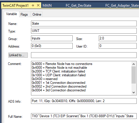
FC_Get_Adapter_State
The current Ethernet IP Scanner status can be returned with this function.
VAR
| FUNCTION FC_Get_Adapter_State : DUT_EIP_Adapter_State VAR_INPUT in:UINT; END_VAR |
PROGRAM
| FC_Get_Adapter_State.RemoteNodeNoConnection[1]:=in.1; FC_Get_Adapter_State.RemoteNodeNoConnection[2]:=in.2; FC_Get_Adapter_State.RemoteNodeNoConnection[3]:=in.3; FC_Get_Adapter_State.UDPClientInitFailed:=in.12; FC_Get_Adapter_State.TCPClientInitFailed:=in.13; FC_Get_Adapter_State.RemoteNodeNotReachable:=in.14; FC_Get_Adapter_State.RemoteNodeNoConnection:=in.15; |
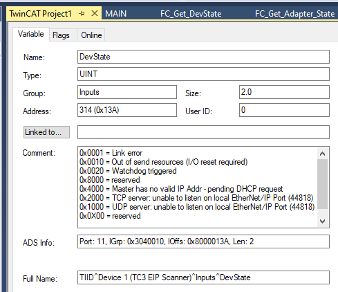
FC_Get_DevState
The current Ethernet IP Adapter status can be returned with this function.
VAR
| FUNCTION FC_Get_DevState : DUT_EIP_DevState VAR_INPUT in :UINT; END_VAR |
PROGRAM
| FC_Get_DevState.Normal:=in =0; FC_Get_DevState.Error:=in<>0; FC_Get_DevState.LinkError:=in.0; FC_Get_DevState.IOResetRequired:=in.4; FC_Get_DevState.WatchdogTriggered:=in.5; FC_Get_DevState.UDPServerUnable:=in.12; FC_Get_DevState.TCPServerUnable:=in.13; FC_Get_DevState.MasterNoValidIP:=in.14; |
MAIN
We will call the RWM() to process the IO-LINK data,and use the Beckhoff TwinCAT3 Ethernet/IP API to send the Get_Attribute_Single and Get_Attribute_All Service messages.
VAR
| PROGRAM MAIN VAR //IO-Link Devices RWM1 :FB_Contrinex_RLS_1181_320; //Get Attribute Signle Get_Attribute_Single:FB_GET_ATTRIBUTE_SINGLE; bExecute_Get_Attribute_Single :BOOL; RawData_GetAttribute_Signle:ARRAY[0..255]OF BYTE; ProductName :STRING(31); R_TRIG_Get_Attribute_Single:R_TRIG; //Get Attribute All RawData_GetAttribute_All :ARRAY[0..255]OF BYTE; R_TRIG_Get_Attribute_All :R_TRIG; bExecute_Get_Attribute_All :BOOL; Custom_Service:FB_CUSTOM_SERVICE; SourceOffset :UINT; NumberOfBytes :UINT; Object01 :DUT_EIP_Object01; //Configuration sIPv4Addr :T_IPv4Addr; sNetId :T_AmsNetID; END_VAR |
PROGRAM
| //IO Link Devices RWM1(); //Explict Message sIPv4Addr:=’192.168.1.11′; sNetId:=’192.168.1.18.2.1′; //Example1, Get Attribute Single R_TRIG_Get_Attribute_Single( CLK:=bExecute_Get_Attribute_Single ); IF R_TRIG_Get_Attribute_Single.Q THEN MEMSET( ADR(RawData_GetAttribute_Signle) ,16#0 ,SIZEOF(RawData_GetAttribute_Signle) ); END_IF Get_Attribute_Single( sIPv4Addr:=sIPv4Addr ,sNetId:=’192.168.1.18.2.1′ ,bExecute:=bExecute_Get_Attribute_Single ,nClass:=1 ,nInstance:=1 ,nAttribute:=7 ,pDst:=ADR(RawData_GetAttribute_Signle) ,nMaxLen:=SIZEOF(RawData_GetAttribute_Signle) ); IF NOT Get_Attribute_Single.bBusy AND bExecute_Get_Attribute_Single THEN MEMMOVE( destAddr:=ADR(ProductName) ,srcAddr:=ADR(RawData_GetAttribute_Signle) ,n:=Get_Attribute_Single.nDataLen ); bExecute_Get_Attribute_Single:=FALSE; END_IF //Example2, Get Attribute All R_TRIG_Get_Attribute_All( CLK:=bExecute_Get_Attribute_Single ); IF R_TRIG_Get_Attribute_All.Q THEN MEMSET( ADR(RawData_GetAttribute_All) ,16#0 ,SIZEOF(RawData_GetAttribute_All) ); END_IF Custom_Service( sNetId:=sNetId ,sIPv4Addr:=sIPv4Addr ,nClass:=1 ,nInstance:=1 ,nAttribute:=1 //can not be zero ,nServiceCode:=16#1 ,pSrc:=0 ,nMaxLen:=SIZEOF(RawData_GetAttribute_All) ,bExecute:=bExecute_Get_Attribute_All ,pDst:=ADR(RawData_GetAttribute_All) ); IF NOT Custom_Service.bBusy AND bExecute_Get_Attribute_All THEN //The first 14 Bytes MEMMOVE( ADR(Object01) ,ADR(RawData_GetAttribute_All) ,TO_UINT(14) ); MemMove( ADR(Object01.ProductName) ,ADR(RawData_GetAttribute_All[15]) ,TO_UINT(RawData_GetAttribute_All[14]) ); //13=Frame Bytes size before Product Name //+1 is mean the Data[14] is the data leneght of Product Name, but not include this byte SourceOffset:=13+RawData_GetAttribute_All[14]+1; NumberOfBytes:=Custom_Service.nDataLen-SourceOffset; MemMove( ADR(Object01.State) ,ADR(RawData_GetAttribute_All[SourceOffset]) ,TO_UINT(NumberOfBytes) ); bExecute_Get_Attribute_All:=FALSE; END_IF; |
ASSIGN
Do not forget to assign the variables in your program.
It is possible to link several variables in one time – if the data size in bytes are the same.

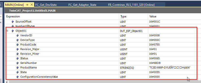
RESULT
The attribute of Object 0x01 Product name is received if we use the GET_Attribute_Single Function Block.
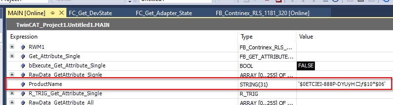
And we can get all Attributes by entering a Service code of Get_Attribute_All in the FB_Custom_Service.