Hi and this time i will show how to use FX5CPU to communicate with RS485 Interface devices with ModBus. May be you can check this link first to get some information about how to modify the setting in GXWorks3 and some configuration about FX5U.
Mitsubishi FX5CPU Apps With RS485[Non-Protocol Communication]
What is Modbus?
From Wiki:
Modbus is a serial communications protocol originally published by Modicon (now Schneider Electric) in 1979 for use with its programmable logic controllers (PLCs). Simple and robust, it has since become a de facto standard communication protocol, and it is now a commonly available means of connecting industrial electronic devices.
Communication Setting With GXWorks3

Programming
In here I will explain how to make the PLC Program that with MODBUS_RTU_Communication.
Step1- Check the Instruction
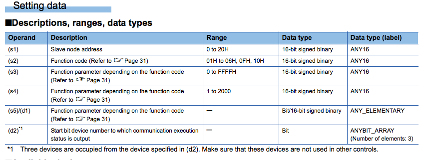
Instruction “ADPRW” is the main in here.


Reference to the Manual:
This instruction allows to communicate (read/write data) with the slave station by the function code which is supported by the
master.

S1 is the Slave node address that in the Devices that you need to communicate with.
S2 is the Function Code of Modbus. Reference to Manual P31, ONLY these Function Code is supported of FX5CPU:
01H:Read Coils
02H:Read Inputs
03H:Read Holding Register
04H:Read Input Register
05H:Write Coils
06H:Write Holding Register
0FH:Write Multiple Coils
10H:Write Multiple Holding Register
S3 is the Modbus address that you want to read/Write.
*Memo:if you wan to read data from address 0005,you should put 0004 in here.
S4 is the numbers of Devices that you want to read/Write.
S5/d1 is the devices that you would like to start to send or receive.
d2 is the condition flag of the instruction.
Step3:Coding
[php]
/**MODBUS Communication Example**/
//s1:=Slave Address
//s2:=Function Code
//s3:=Function Code Parameter
//s4:=Function Code Parameter
//s5/d1:= Data Send/Receive starting address
//d2:=communication condition
//Read the input register into Slave station H01 of address k4, and save the data that start from D400, Finally output the condition flag to M20,M21 and M22
ADPRW(TRUE,H01,H04,K04,K2,D400,M20);
IF M20 THEN
//the instruction is finished in normal
//do some data operation
//reset the condition flag
ZRST(TRUE,M20,M23);
ELSIF M22 THEN
//the instruction is finished in error
//do some alarm output
//reset the condition flag
ZRST(TRUE,M20,M23);
END_IF;
[/php]
Some Trips:
It is better(for me) to use 0FH and 10H to write the data into coils or register, and then just change the S3 to how many data that you want.Just forgive 05H and 06h ;)!
Here is the link to get more information about it:)!
FX5M
FX5 User’s Manual (MODBUS Communication)
See u next time and just write down the comment if you have any question ;)!