TF1800 &TE2000?
This series I will try to explain the Beckhoff HMI programming. Some People will confuse that in Beckhoff there are 2 types of Hmi packages – TF1800 PLC HMI and TE2000 HMI.
We know that Beckhoff’s PLC is running on a PC with Windows7/10/CE but also has HMI applications.This type of application is TF1800.
Reference to the Manual,
The PLC HMI is an extension of the runtime system and enables the visualization to be executed on the control computer or a third computer without a development environment. The visualization code is created based on the existing visualization objects and downloaded to the control computer. Avoiding the use of the development environment results in significant memory savings. This can be useful for small computers.
TE2000 is a package for the Engineer to create the HMI projects on a real “HMI”.
Please take care that PLC HMI is not allowed to make connections directly to other PLC(siemens,rockwell..). It is only for the controller of beckhoff.
Create the Project
Let’s make some sample PLC HMI Applications now.
File>New>Project.. to create your new TwinCAT Project.
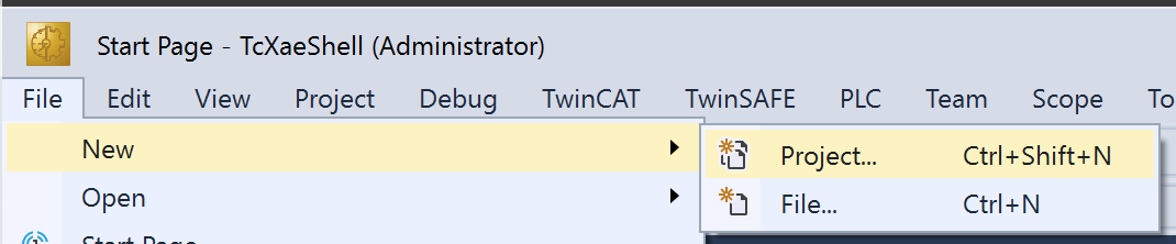
Please choose the TwinCAT XAE Project here.
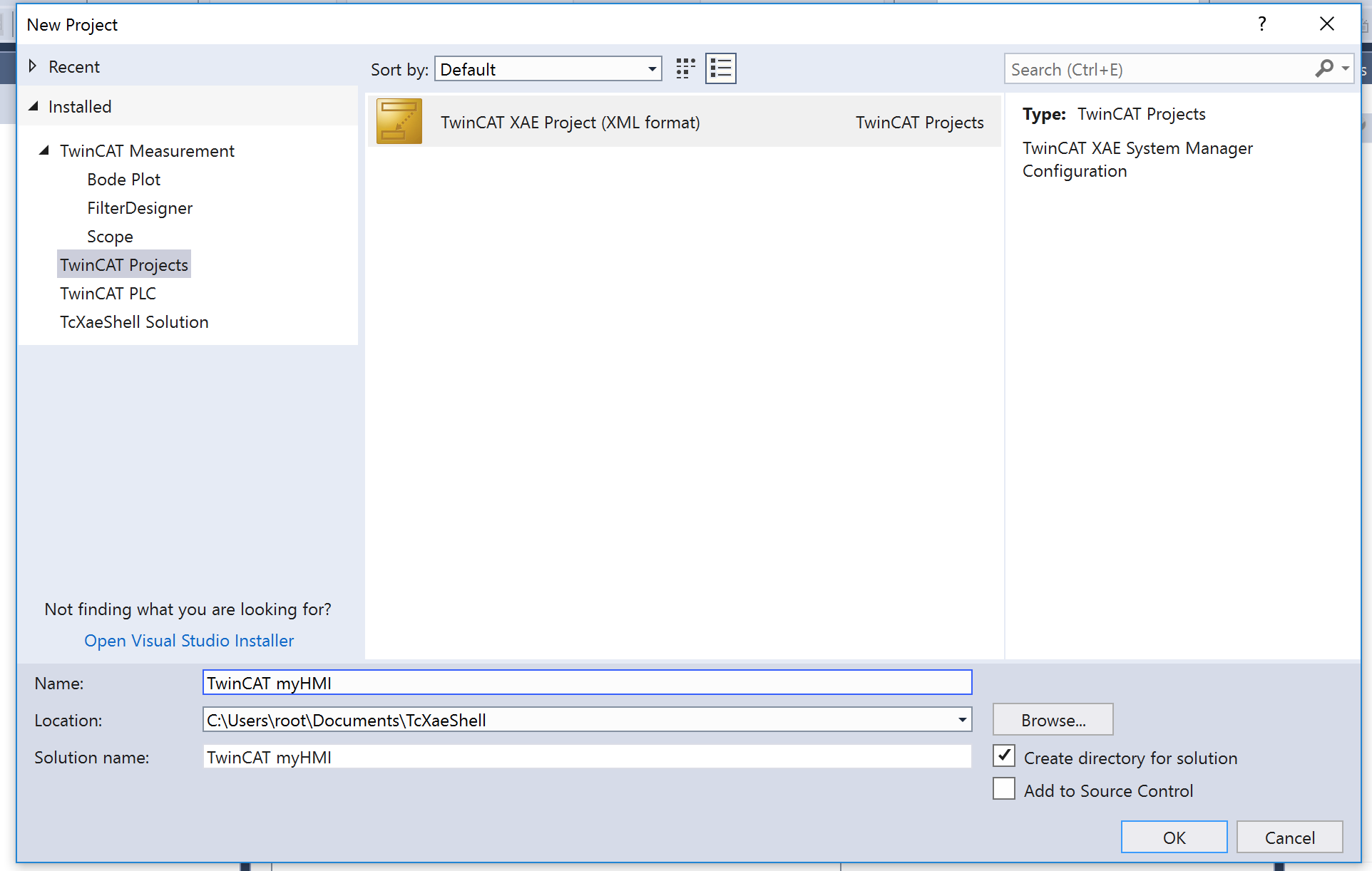
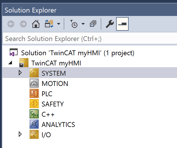
Now the new TwinCAT Project is created.
Insert PLC
just add some new variables that we can view in the PLC HMI applications.
PLC>Add new Item..
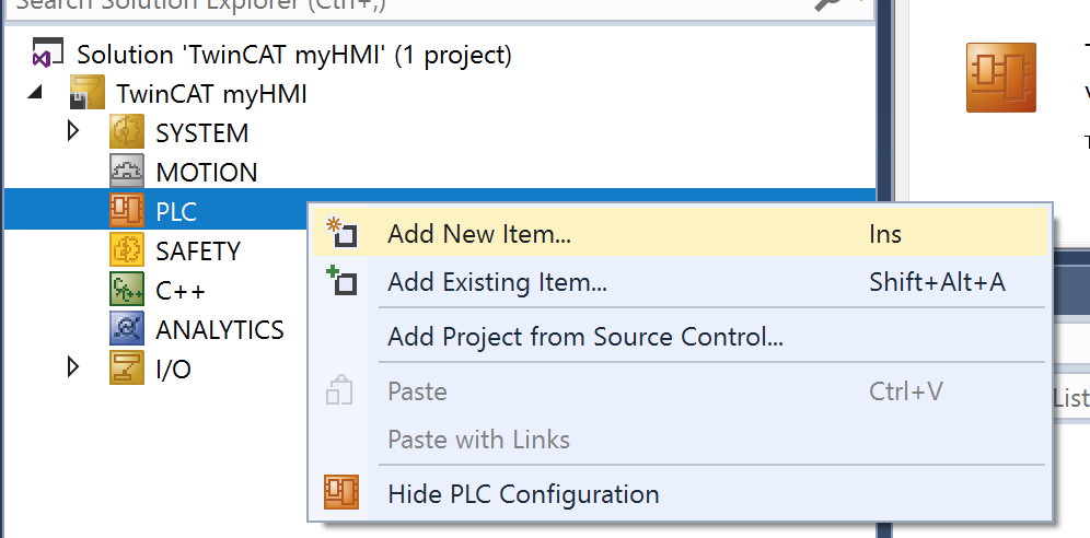
Select Standard PLC Project and press OK.

OK, PLC Project is inserted in your solution now.
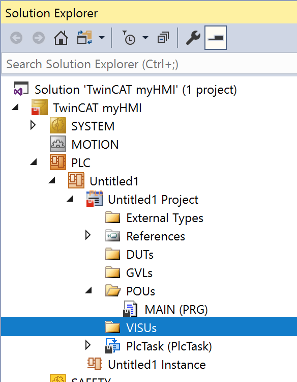
Would you see a folder named VISU?
It is the folder that save all your screen data.
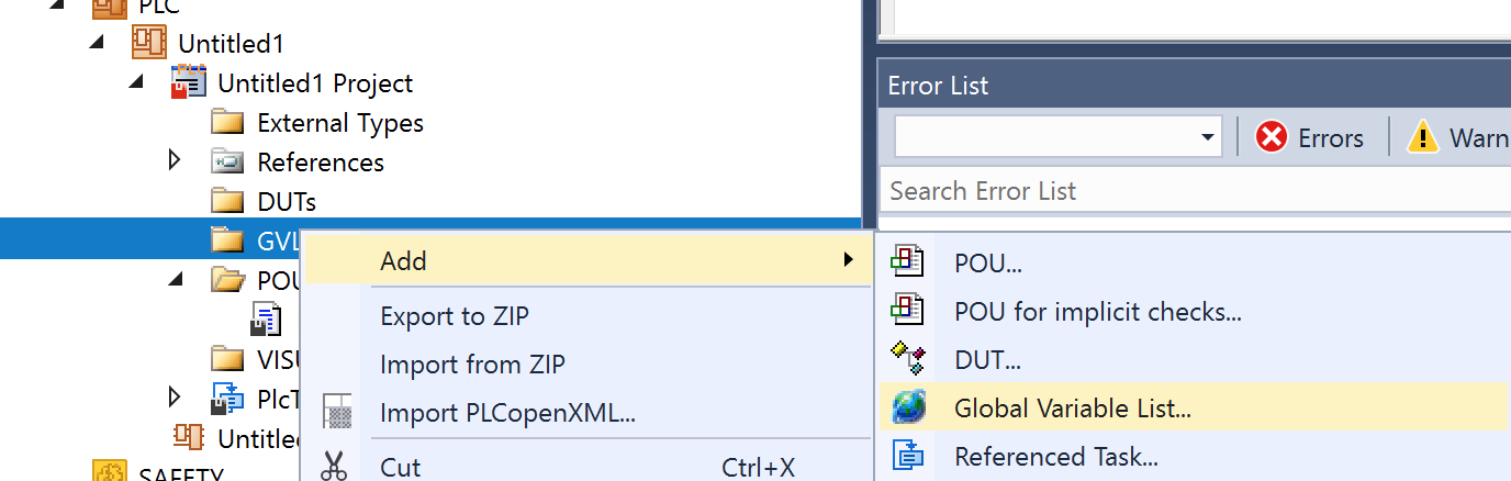
Let’s create some Global variables in the GVL.
GVL>Add>Global Variable List
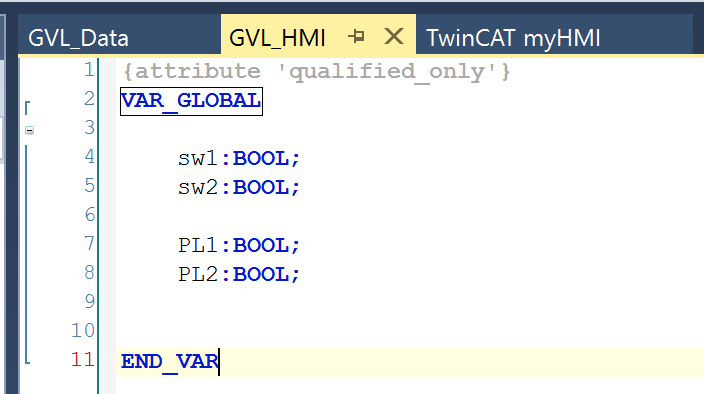
Define some variables in the List for lamp and switch.
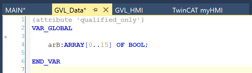
And then create one more list with a Bool array.
Insert PLC HMI
Now we can insert a PLC HMI in our project.
VISU>Add>Visualization..
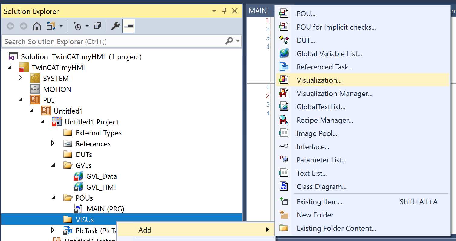
Check the box of Active and Open it.

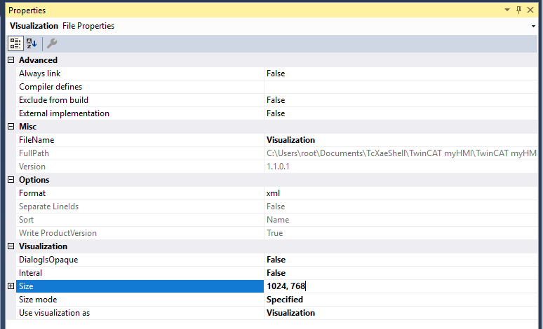
Adjust the Screen Size
we can change the screen size to Specified, AutoDetect or AutoDetectwithBgImage.
Please select the screen that you would like to change the size and adjust it in the size mode tab.

I would like to make a fixed size screen – So Specified is selected in the Size Mode and I can enter the size in the “Size” text field.
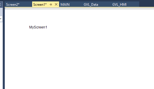
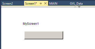
After the Screen size is changed, rename your screen.

Just using Ctrl+C and Ctrl+V to copy 1more screen1 and named as Screen2.

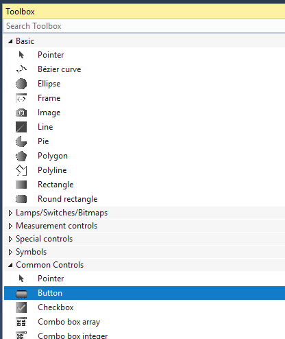
Insert Label
Go back to Screen1 and click the Toolbox Tab.

You can see lots of HMI Item.

Let’s add some Labels. Select the Label object and drop it to your screen.

And you can input some text into your Texts>Text field.

Label setting is OK.
Insert Button
select Button in the toolbox menu and drop it into screen.
Now the button is inserted in your screen.
you can change the style of the element in the PLC HMI.
Please open Visualization Manager.

In the Selected Style options, you can choose the style of your Applications.
Umm, Let’s try 2,3,1.6.0.
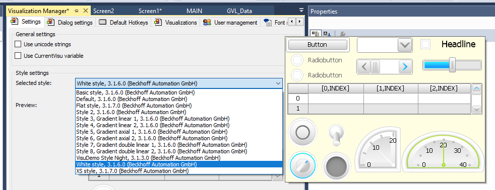
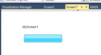
The Color of the button is changed.
Insert Event
We would do some action while the button is pressed.
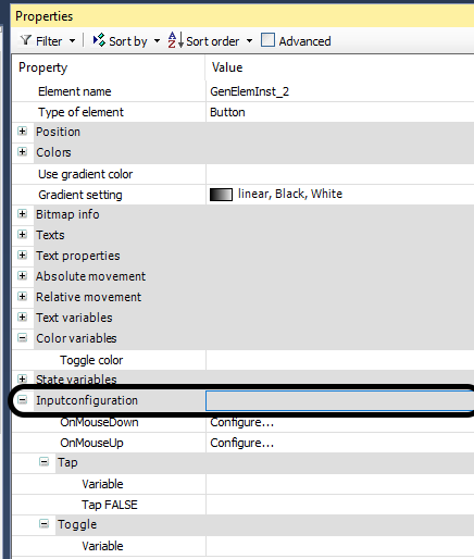
Please select the button that you inserted.

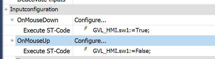
Open the Inputconfiguration Tabs.
we can set the Trigger conditions of the Button.
OnMouseDown:Triggered while button is pressed.
OnMouseUp:Triggered while button is released.
Configure the OnMouseDown Actions.
Input Configuration pop-up is shown while OnMouseDown is Click.
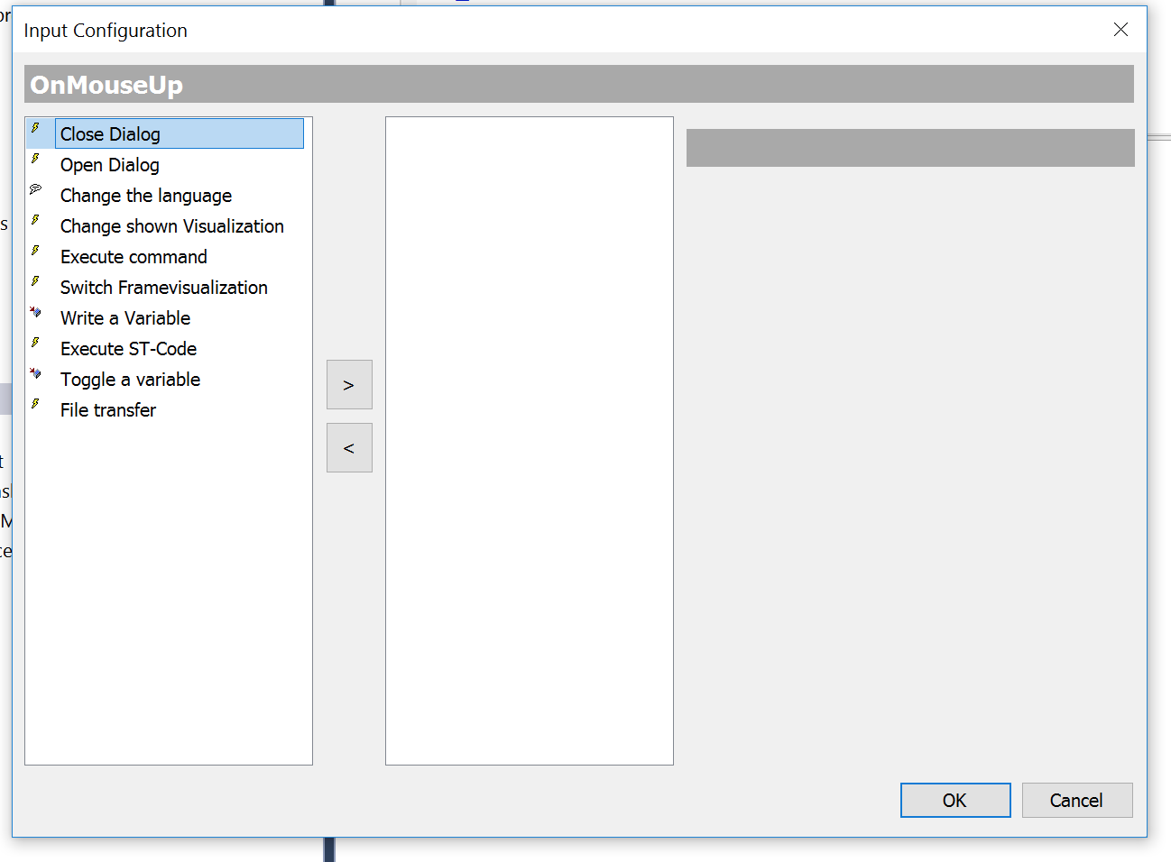
Select Execute ST-Code, then press “>”
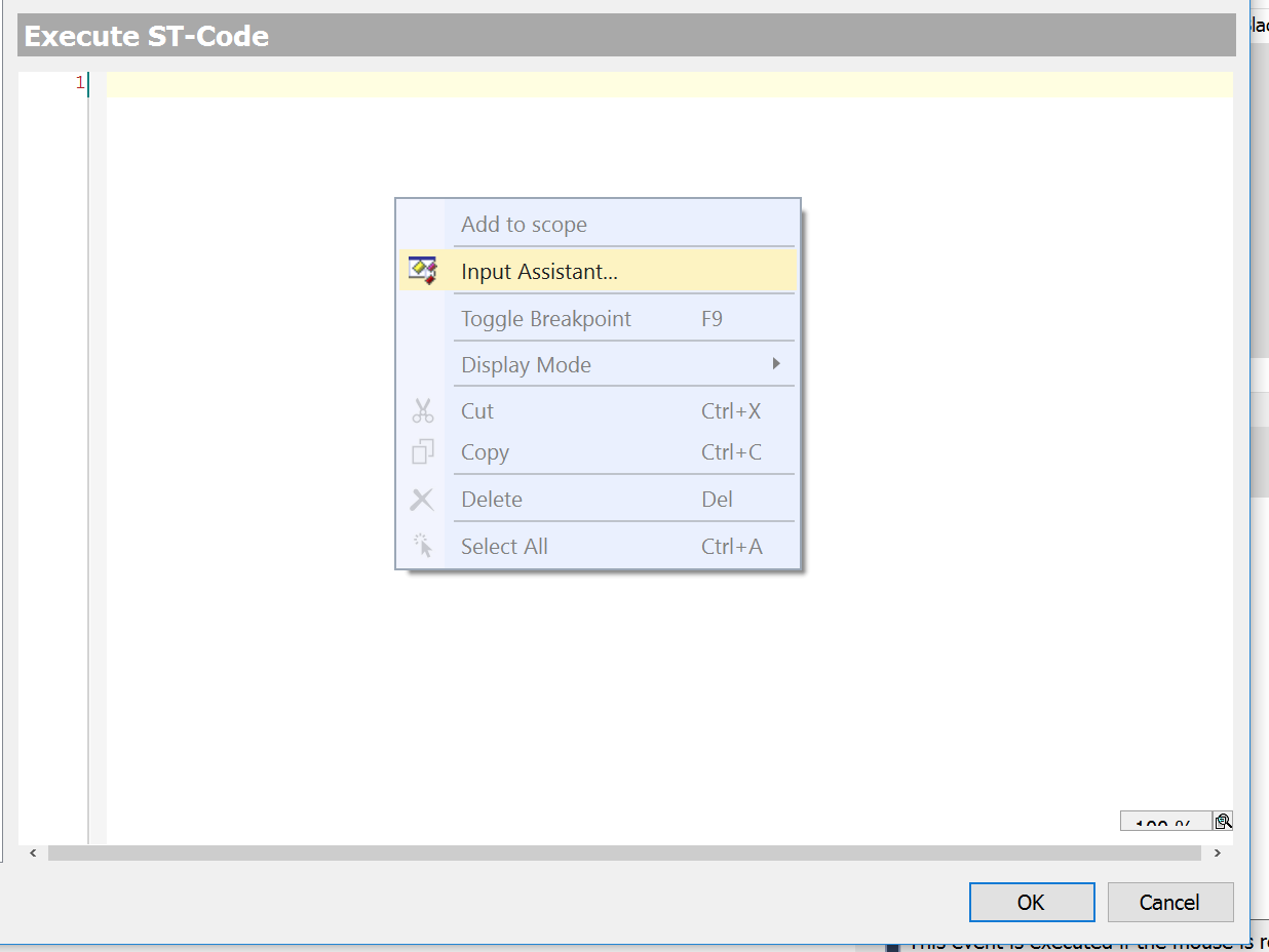
now some ST-Code will be executed while this button is pressed.

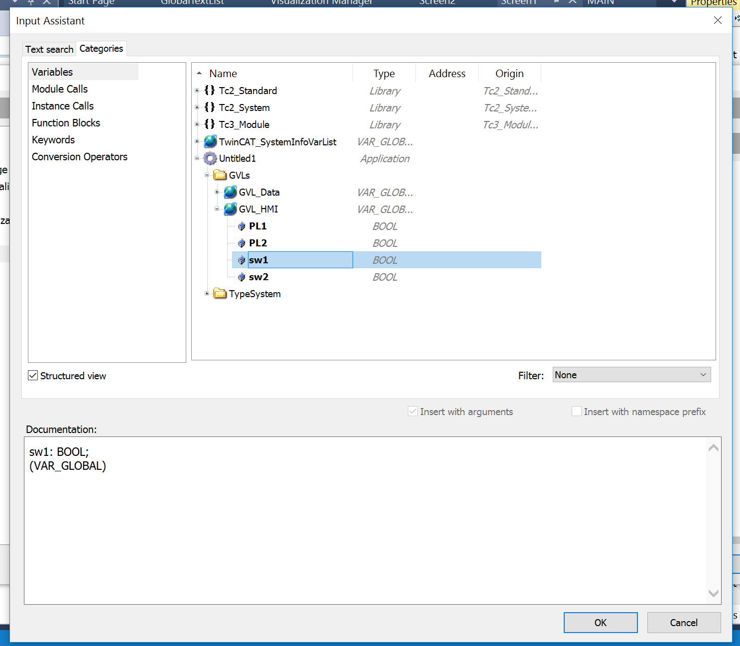
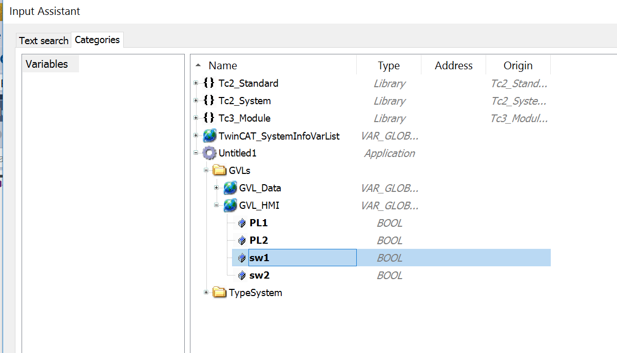
Right click>Input assistant.
choose the variables that were created before in your project.

GVL_HMI.sw1 is selected , then press OK.
GVL_HMI.sw1:=TRUE;
Now GVL_HMI.sw1 will be true while Button is pressed

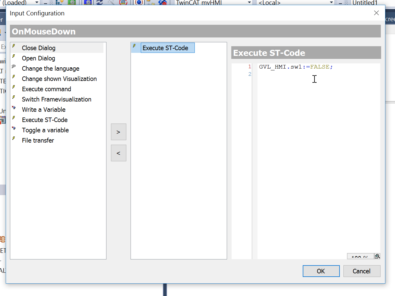
Next make the same setting with MosueUP.
But this time we will program in this way:
GVL_HMI.sw1:=FALSE;
GVL_HMI.sw1 will be False while Button is released.
Finished 🙂
Color Change
Here are the Steps to show how to change the color.
Select the button>Open the Color tab.
Color is Normal Color and Alarm color is the setting while the button is pressed.
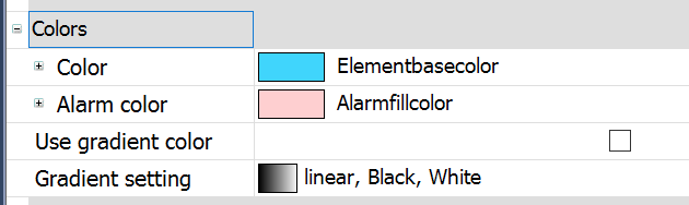
Just choose any options that you want:)

Now Red is set.

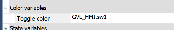
Finally, you need to configure which variable is used to control the color change.
Color variables>Toggle color.
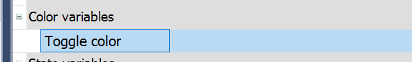
Just configure it.
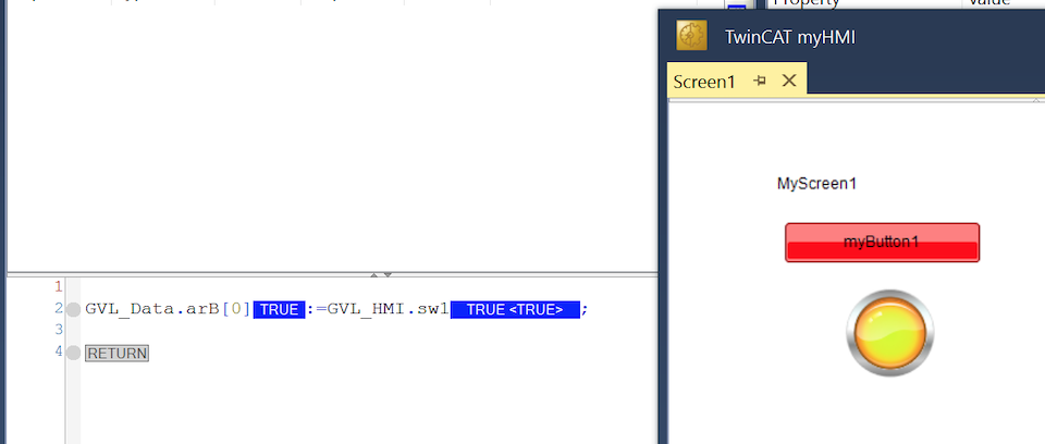
now the button ‘s color will be changed to Red while button is pressed.
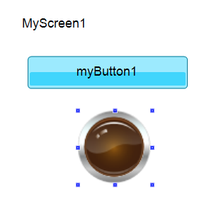
Insert Lamp
Doing the same things.
Drop the Lamp Item to your screen.

The lamp image is like this.
you can change the colors in the Properties>Background>Image.
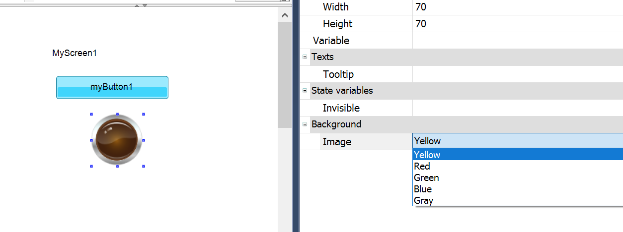
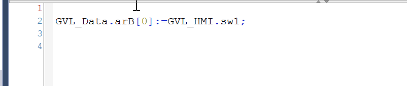
Oh, forgot to write some program inside the PLC.
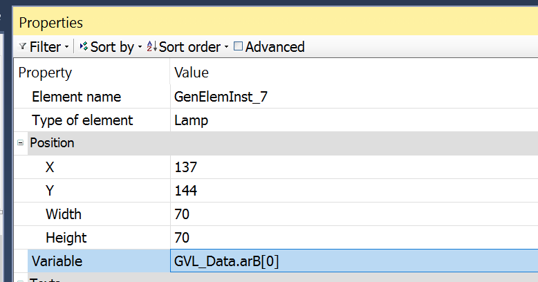
Please configure which variables to affect the color in Properties>Variable.

GVL_Data.arB[0] is configured.
Implement
Let’s build your solution.
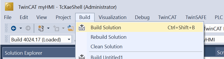
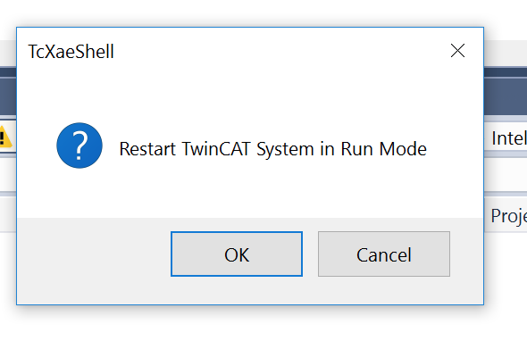
Please confirm that there are no errors inside your project. Then Reset TwinCAT System.
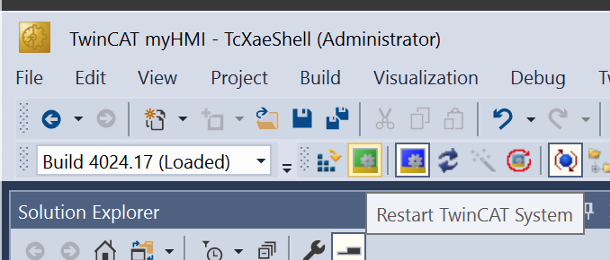
OK, I would like to reset it.
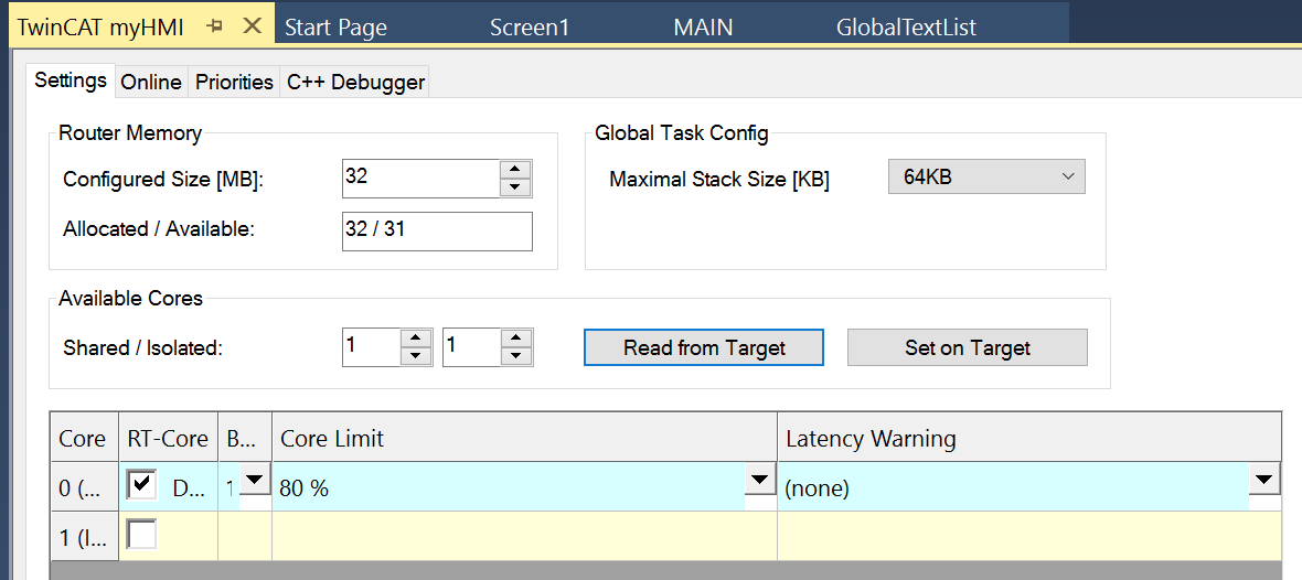
Do not forget to set your Real-Time Target.
Please Download the Project.

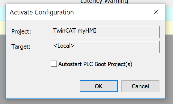
Click OK to activate the Configuration.
Please take care of the Autostart PLC Boot Project(s) Checkbox.
Before fully testing your TwinCAT Project, please do not check it.
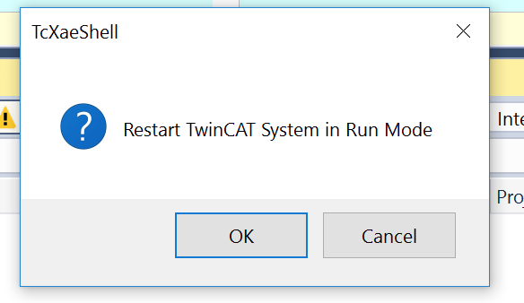
Restart.
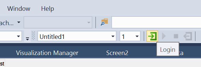
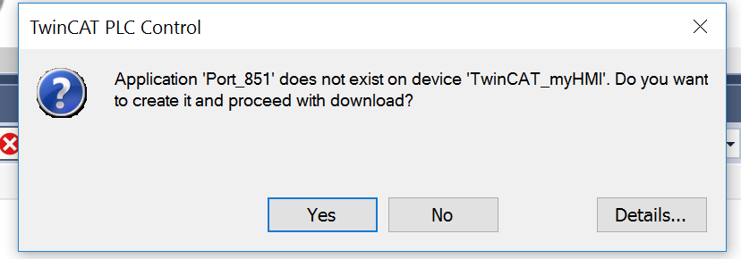
Download the PLC Project by Login Button.
YES.
Start.

This is your init Conditions.
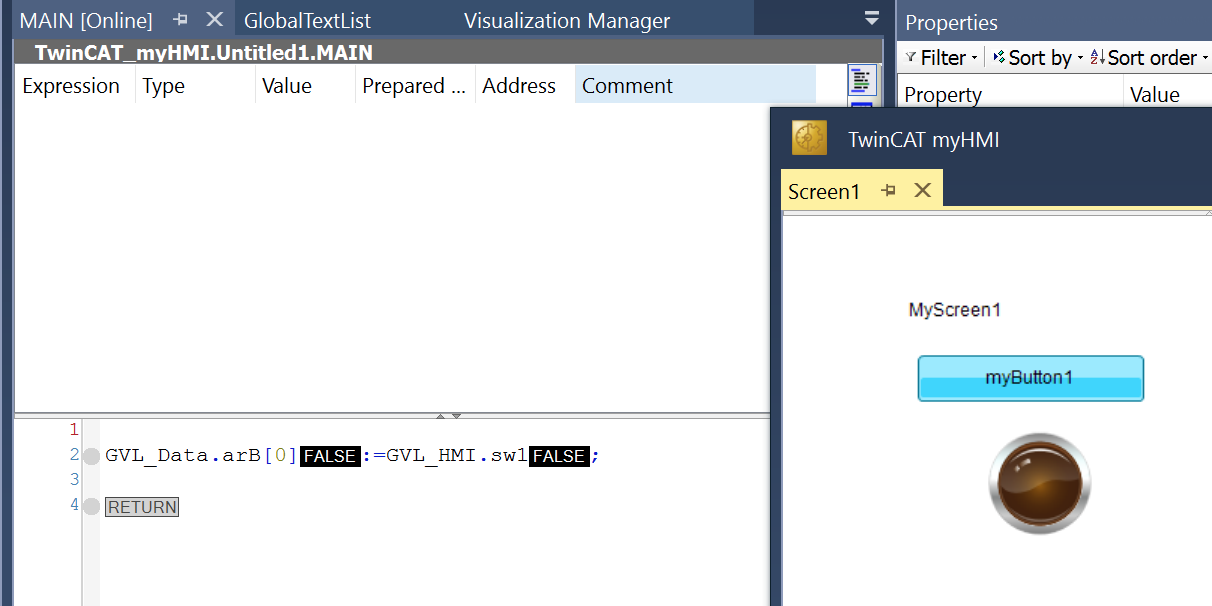
The lamp ‘s color will be change while button is pressed.
You can download the project in the below link:
https://github.com/soup01Threes/TwinCAT3/blob/main/TwinCAT%20Project_PLCHMI_TF1800_1.tnzip
Please feel free to ask any question.
Connect Me by Email:soup01threes*gmail.com (*>@)
Connect ME in Twitter: @3threes2