We can use TwinCAT TF6620 to implement the communication between Siemens PLC.
TwinCAT System will use the IO Configuration and library that is supported by Beckhoff.
And also, Only Absolute Address in S7 CPU is possible in this operation.

System Requirment

Manual
Installation
Please access this link and click on the Software and tools tab.

Download the latest version.

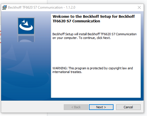
Please choose english.

Press Next.
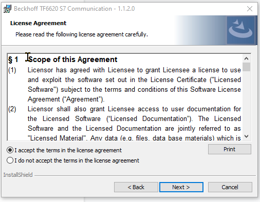
Agree the License and press next.
Enter your User name and Organization, press next.

Choose Complete and press Next.

Press Install to start the installation.

Please wait until you finish..

Completed.

And then restart your PC.

Implementation
Now I will start to show how to implement this, do not worry, there are no complex things!
TwinCAT Install real-time Ethernet adapter
TF6620 is based on the TwinCAT real-time Ethernet adapter. You must install this Driver first.
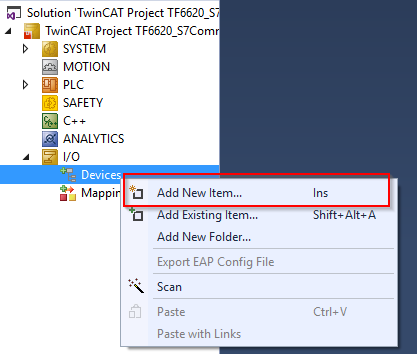
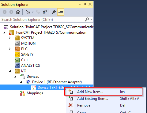
Solution>Project>I/O>Devices>Add New Item.
Select Ethernet>Real-Time Ethernet Adapter(..) and OK.
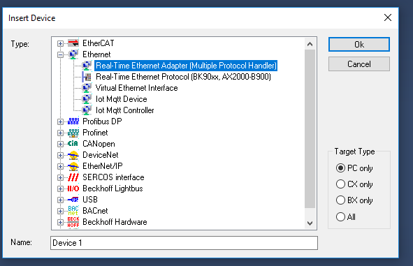
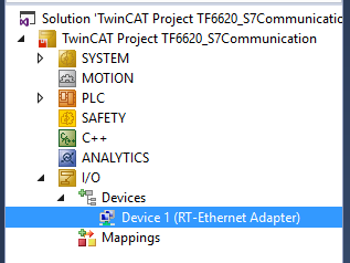
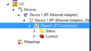
Now the RT-Ethernet Adapter is inserted.
Insert the S7 Communication Driver
After the real-time ethernet adapter is inserted, now right click the device that you inserted>press Add Object(s).

Choose Beckhoff Automation GmbH>TcloEth Modules>TCP.UDP RT(Module).
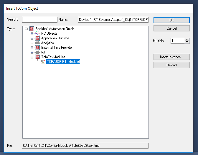
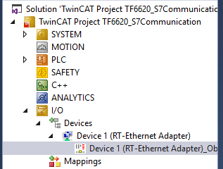
TCP.UDP RT(Module) is inserted.
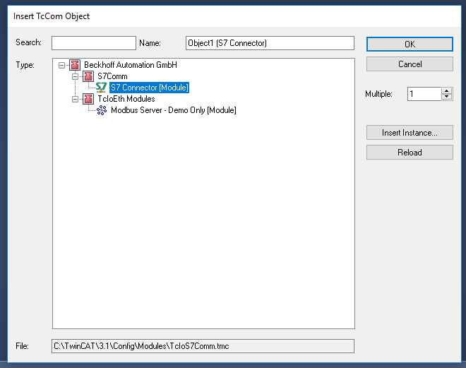
then select this item and right click>Add new Item.
Choose Beckhoff Automation GmbH>S7Comm>S7 Connector(Module).
S7 CPU Communication settings
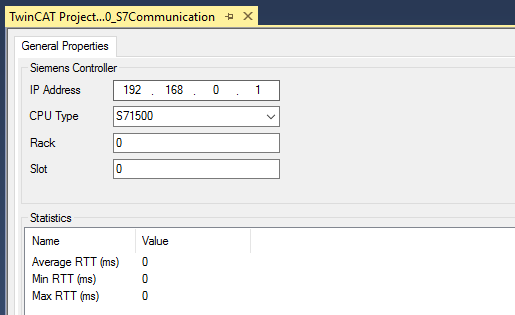
After the S7 Connector is inserted, double click the object.
Enter the IP/CPU Type/Rack Slot.

This time I am using the S7-1500.
IP is 192.168.0.1
Rack and slot is 0.
Mapping
Now we can configure the data map.
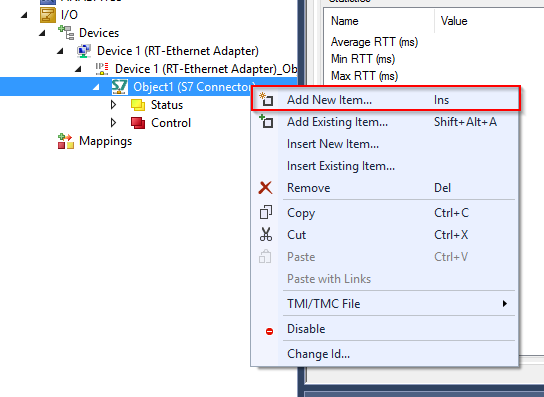
Select Object1 > Right Click>Add New Item.
S7 Single Request And S7 Cycle Request
We can choose Single Request and Cycle Request here.
It depends on the trigger condition.
S7 Single Request – the request will be sent while the variable SendRequest is increased.
S7 Cycle Request – just cyclic.

Single Request
This time I will implement the S7-Single Request first.Please choose S7 Single Request >OK.
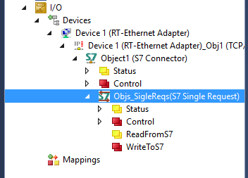
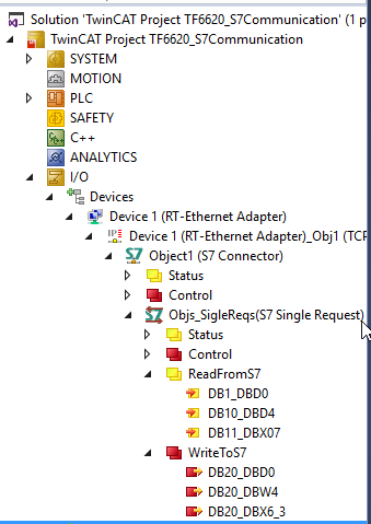
you can see Status/Control/ReadFromS7/WriteToS7 is inserted.
ReadFromS7 is the data that gets from S7-1500.
WriteToS7 is the data that is sent to S7-1500.
if you double click the object item, Read Variables and Write Variables is displayed in your right hand side.you can config the data exchange in here.
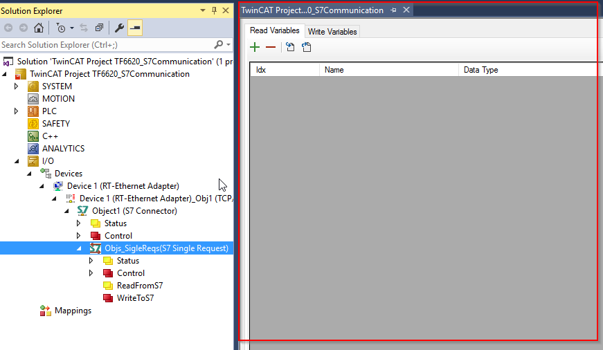
Read Variables
Click the + Button to add some variables that read from S7-1500.
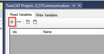
a row with Idx=1 is inserted.
I will explain the Data structure of Siemens PLC, please do not worry.
Let’s set the Data Type to 32 Bit Dword.

S7 Data AreaはDATA_BLOCKSにします。
Then choose DATA_BLOCKS in the S7 Data area column.

It means- start from 0 bytes , there are 4 bytes of data will read from S7-1500, and the data type is Dwod.

Let’s set a little more.
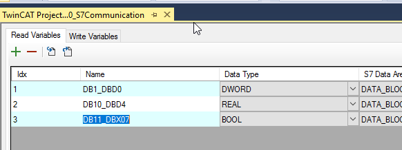
Please take care in the S7 Data Block field.
1:DB1,0Byte-3Byte、DWORD Type。
2:DB10,4Byte~7Byte、Real Type。
3:DB11,0Byte Offset 7、Bool Type。

It is better to have a good variable name.
Write Variables
The Writing Variables setting is the same as the Read variables.
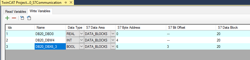
Now you have the items of ReadFromS7 and WriteToS7.
Siemens Side
Now it is Siemens PLC Side.
Create a new project and click on the Device Configuration.
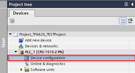
Click the Properties tab.

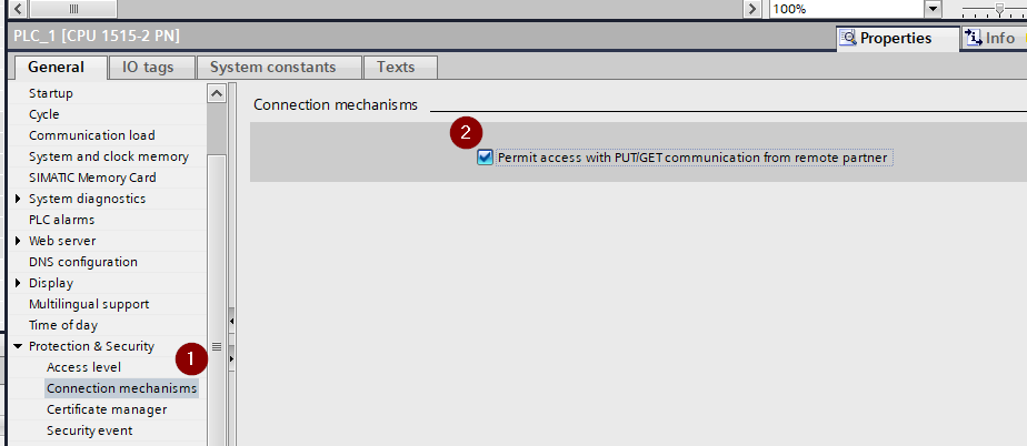
Put the Checkbox of General>Protection & Security >Permit access with PUT/GET…
It is the option of Security in S7-1500.
if the checkbox is un-check, you can not access any data by using S7-Communication.
Create the DB
Then create the DB for Read and Write.
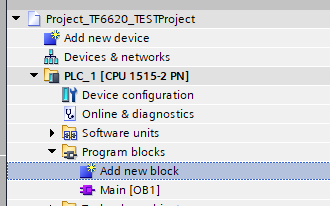
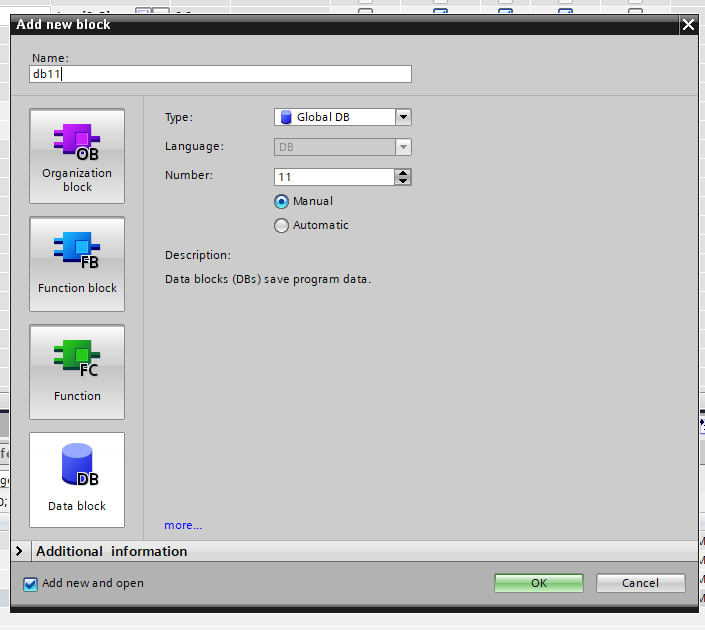
Go to Program Blocks and click the “Add new block”.
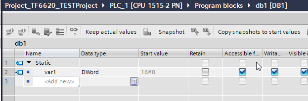
using any name that you like.

Add the variables that you created in the TwinCAT Projects.
Select the DB and Right Click>Properties.
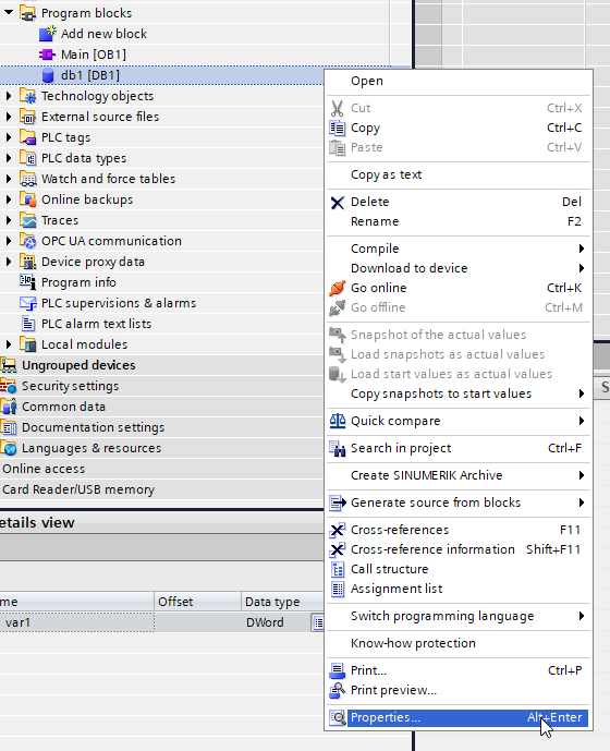
Uncheck the General >Attributes>Optimized block access.

Now you can see a new column in the DB Blocks.
It is the Offset – the Byte address setting in the TwinCAT Project.
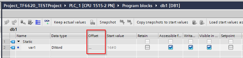
Press Ctrl+B to Compile the block, you can see 0.0.
It means the absolute address of var1 is DB1.DBD0

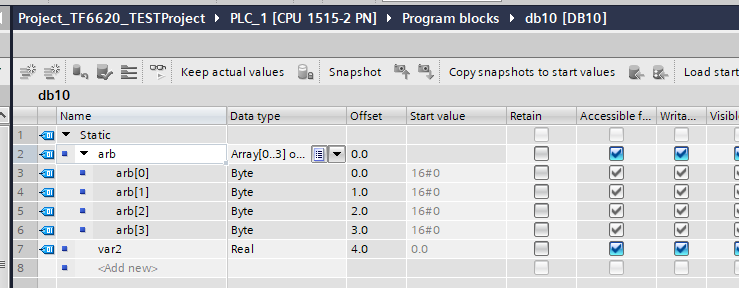
Doing the same thing as DB10.

Manual Change the DB number to 10.
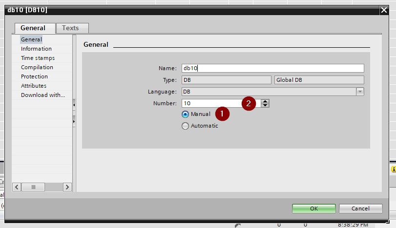
Now the DB Number is 10.

In the DB10, var2 is a real variable and offset=4.0. It means the Absolute address is DB10.DBD4.
Last one the DB11.you can choose “Manual” while creating the DB. Then enter any number that you want.
I will define a 16 length bool array side.
Do you remember the Offset of the bool device that you set in TwinCAT project is 7?
It means the Address is DB11.DBX0.7.
Please take care that the addressing in Siemens is starting from Zero.

Please Do the same way in the Write Variable.

Address GAP
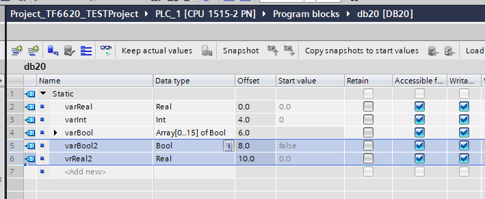
The topic of this post is not Siemens, but did you see the variables that I defined – Always as 2 bytes or 4 bytes units?
There is a story of Siemens DB Address concept.
For example, in the following Picture, you can see that I inserted new bool variables with Offset 8.0. So- the address of this device is DB20.DBX8.0
Then I insert a new Real variable. the offset changed to 10.0. It means that we wasted 15 bits data.
Test
Perpare
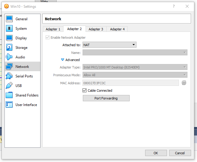
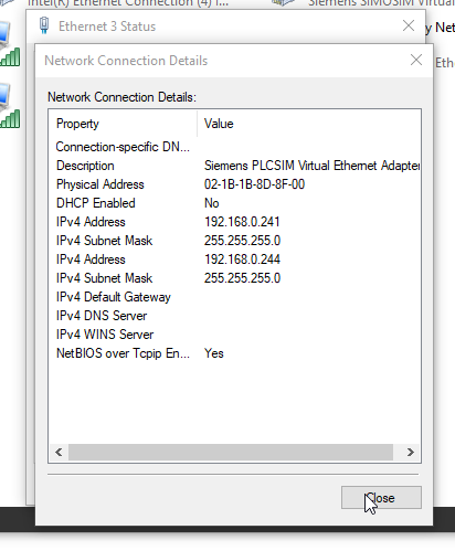
I am using Virtualbox and configuring the following setting of Network adapter.
And Because I do not have a Real S7-1500, I will use PLCSIM Advanced.
It can help me to simulate TCP communication.
If you have an Error of 1823 in TwinCAT,
please refer this link:
Connection
Turn your TwinCAT Runtime in Run Mode, and view the State variable.
TwinCAT Runtime起動したら、最小はStateを見てみましょう。

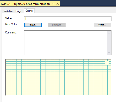
Go to the Online tab to monitor the current value.
0x40 =is connected.

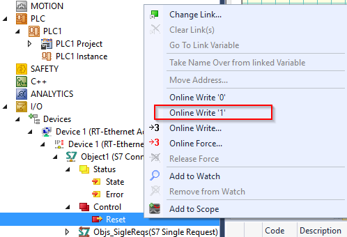
if the connection can not be established, go to Control>Reset>Online Write and Reset it.
Read
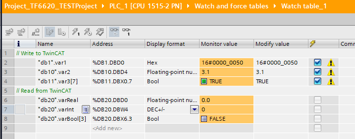
Now Create a Watch Table on the Siemens Side.
Go to the Control >WriteToS&Enable and Set it to true.
Reference the Manual:
Write commands are only executed if this variable was set to TRUE.

Go to the Online Tab and Turn it to True.
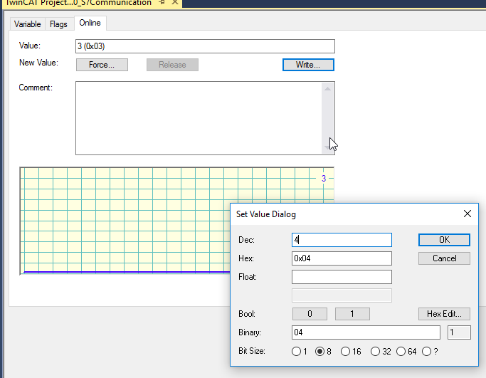
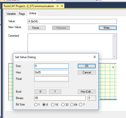
Control >SendRequest.
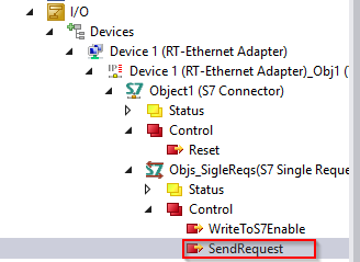
Put a new value inside.

Write it.

Refer to the Manual:
By incrementing these variables from the application code, a read/write command (request) is triggered.
As soon as the associated response has been received from the S7 Controller, the input variable, Status.ReceiveCounter is also incremented by 1
accordingly. The application thus knows that the read/write operation was successful.
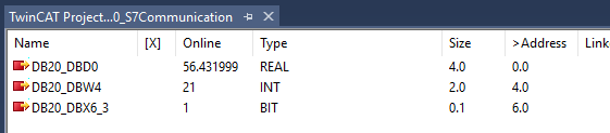
Then ,Click the ReadFromS7.

you can see the value that read from S7-1500.

Write
This time we try to write some values.

you can see all the writable devices in here.
また、SendRequestを+にします。
Increase the SendRequest again.
Good, the value is changed.

Please click the following Link to download the Sample Project:
https://github.com/soup01Threes/TwinCAT3/blob/main/TwinCAT_Project_TF6620__1.zip