In this tutorial I will show you how to implement a cc link connection between IQ-RJ61BT11 and a non-mitsubishi CCLink slave.
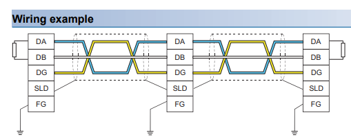
Wiring
New Project
Go to Project>New project to create a new project.
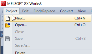
R00 is used in this tutorial.

Project is created.
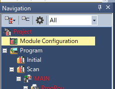
Module Configuration
Double click the Module Configuration.
Insert the R33B
R33B Rack is used here and please insert it first.
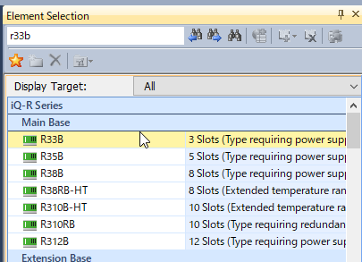
Drop the R33B Rack to your project.
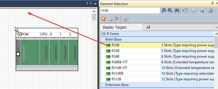
Insert the CPU
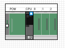
Drop the R00 CPU to your R33B Rack.

Done.
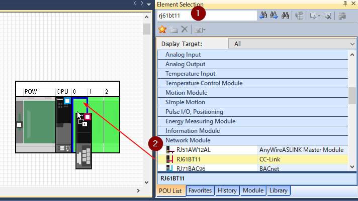
Insert the RJ61BT11
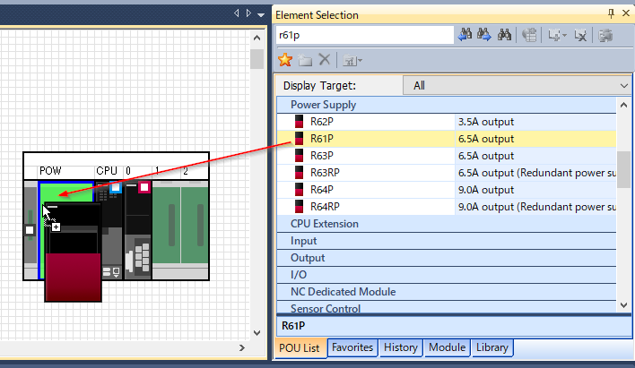
Now we can insert the RJ61BT11 module.
Insert the R61P
Finally please insert the power moule. R61P is used.
Convert your project data to check any errors and download to your CPU.

Diagnostic
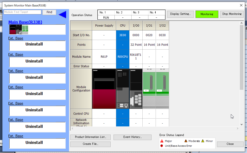
Go to Diagnostic>System Monitor.

The Module is in normal condition.
Parameter setting
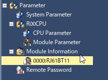
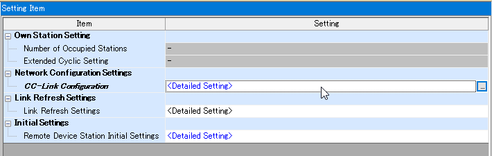
Go to Parameter>Module Parameter>0000-RJ61BT11.
Click the Network Configuration Settings.
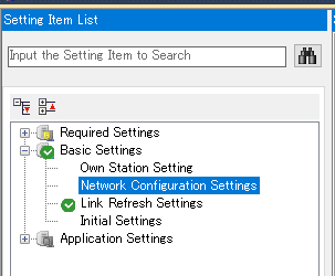
And then click the CC-Link Configurator.
Insert Slave-Method1
The network configuration is shown in the screen,
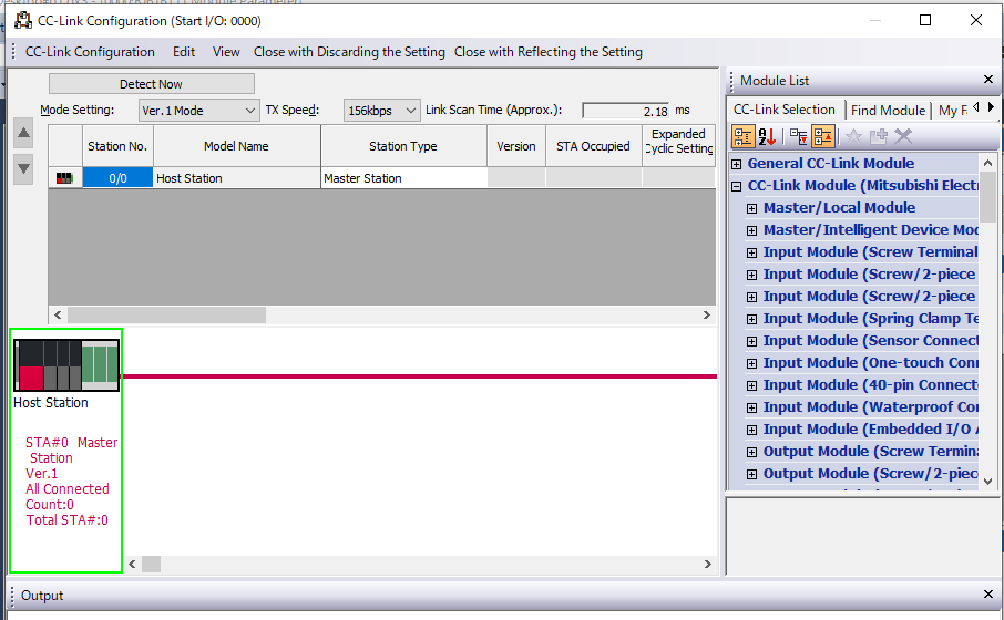
Depending on your devices and the Non-Mitsubishi CC Link module used here, go to General CC-Link Module>General Remote Device Station and drop to the line.

Slave is added.
Insert Slave-Method2
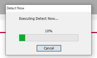
Connect the Slave to your network and Click the detect now button.

Yes.
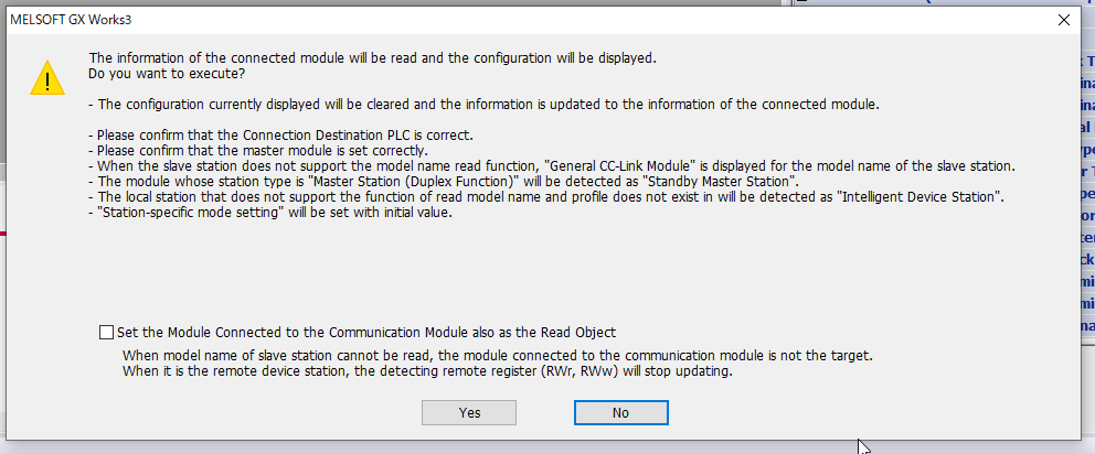
Please wait a mins.
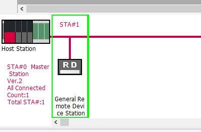
Done.
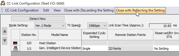
Slave is shown in your network configuration now.

Please make sure the CCLink Version is matched.

Press the Close with Reflecting the settings Button to save your setting.
And also the Master Version.

you can press the check button to check if all parameters are normal or not.
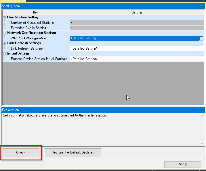
Done.
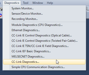
CCLINK Diagnostics
Download your Project and Go to Diagnostic>CC-LINK Diagnostics to check your CC-Link status,
A red icon is displayed if the connection has a problem.
Please check the cable and station number.

The module status is like this.

Program
Let’s create some testing programs.
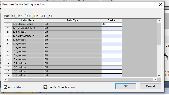
構造体
We will create the INPUT/OUTPUT Structured Data Type.
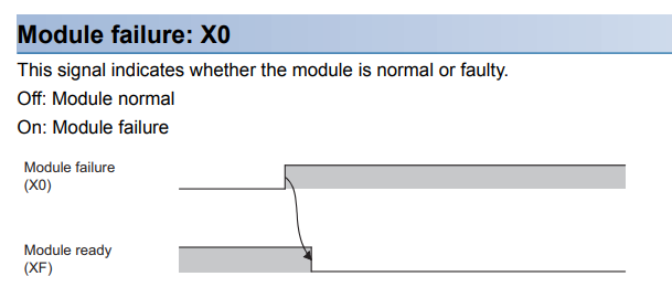
Reference to the Manual Only X0,X1,X3,XF are used and Y is not used.

X0
True=Normal.
X1
True= Master Data Link is processing.

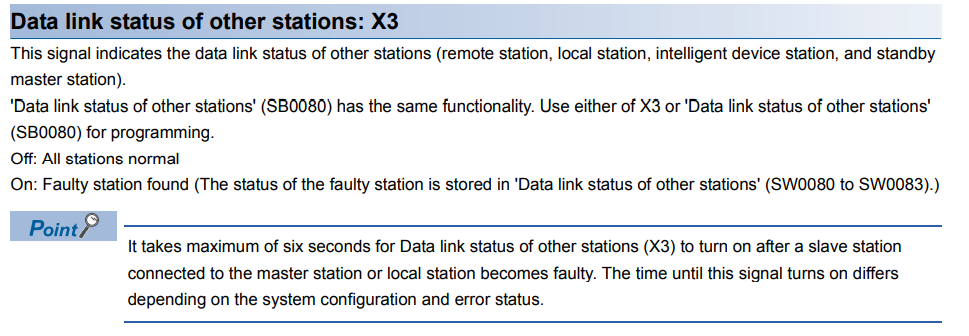
X3
True=At least one device is in error status.
XF
True=Ready.

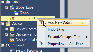
Go to Structured Data Type> Add new Data.
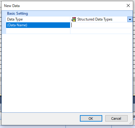
Enter the Structured Data Types name.
And please compile it to check for any errors or not.

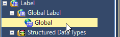
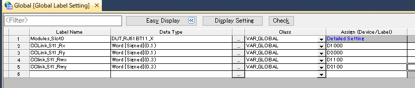
Create the Global Variable
Now we can create the global variable.
Go to Label>Global.
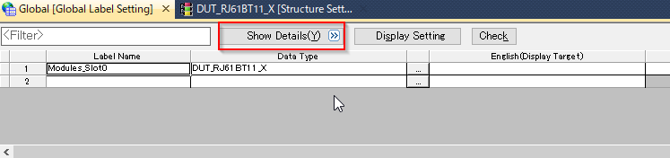
Input your Label name and define the data type as you created in the previous step.
Finally click the Show Details.
Assign(Device/Label) is shown now.please click the Detailed Settings.

Popup is displayed.
you only need to input the first address of your module.
In my case ,X0 is used.
Yes.
All the devices are all automatically assigned.

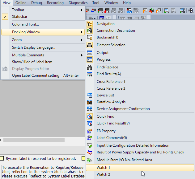
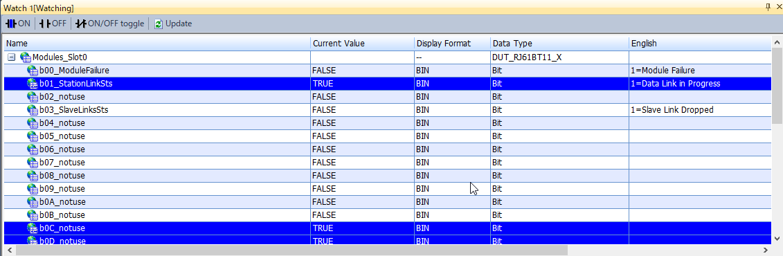
Monitor
Go to View>Docking Window>Watch to show the Watch Table.
please input the label name of your device to view the data.
CCLINK IO Setting
Finally we will setup the IOs between master and slave.
Click the CCLink Module.

Click the Basic Setting.

Press the Link Refresh Settings.
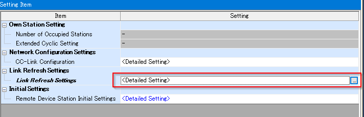
Assign the IO Number to the Devices inside your PLC.

Define the variable
Define the variables as array that depend on your IOs and download the project.
Here is the normal status.

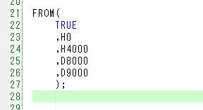
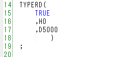
program
We can also use FROM・TO instruction to get/send the data.
TYPEERD is a function to get the name of a module.
Be Careful!
Please check the CC LINK Version of your device.

V2.0 is used in this tutorial, we can use this buffer memory to access the module.

4000hex=Station1..something like this.
