Hello and in this tutorial I will Explain how to play with TwinCAT and SIMIT to simulate the
PROFIdrive-1 Control. Basically PROFIdrive is the standardized drive interface for PROFINET and PROFIBUS,from basic speed control to high-level servo controllers.
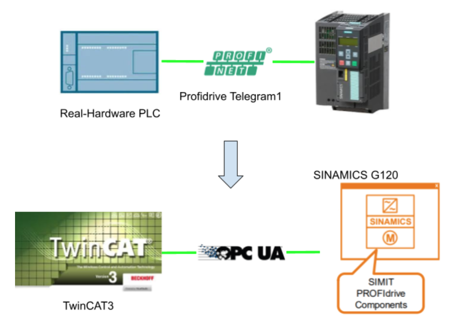
In the real case, the configuration would be like this:
A Real-PLC that supports PROFINET, and then configures the Telegram between PLC and ProriDrive supported devices.
But here I will replace the Real-Hardware with TwinCAT – A software PLC.
The Communication channel will be changed from PROFINET to OPCUA.
FInallyThe SINAMICS G120 will be simulated by SIMIT.
(ADS Driver can be used if you have licenses. )
Although the communication driver has changed, the theory is the same.
your task is still controlling the SINAMICS G120 by PROFIdrive.
Reference Link
Siemens
TwinCAT
PROFIdrive?
PROFIdrive is the standardized drive interface for PROFINET and PROFIBUS,from basic speed control to high-level servo controllers.
There are PZD(Prozessdaten) – process data and STW – control words [DE
Steuerwort] .
Depending on the telegram type used, the numbers of PZD and STW are different.

In Telegram1…
STW1/STW2 and ZSW1/ZSW2 are used in this telegram.
STW1:Control word with commands
STW2:Speed Setpoint
ZSW1:Status word
ZSW2:Actual Speed
Componet
I will explain the components that are used in this tutorial.
PROFIdrive1
The PROFIdrive1 component is a simulation of PROFIdrive Telegram1.

NSOLL_A=Speed setpoint value.
NIST_A =Actual Speed

The NOSLL_A and NIST_A are raw values from 0-16384.
Y is the Speed setpoint from 0~100%, which 100% is the raw speed value of 16384.
We can view the STW1/ZSW1 by clicking this simulation block.

And also ZSW1.3 Fault and ZSW1.7 Warning can be set to True/False by using the toggle switch.

Connectors-Inputs
| Name | Description |
| STW1 | Control word1 of PROFIdrive |
| NSOLL_A | Raw speed setpoint from 0-16384 |
| NIst | Process value Actual speed |
Connectors-Outputs
| Name | Description |
| ZSW1 | Status word1 of PROFIdrive |
| NIST_A | Raw Actual speed from 0-16384 |
| Y | Process speed setpoint from 0-100% |
| NSoll | Process value Speed setpoint |
Universal
Universal is an extension of Profidrive base functions. ZSW1 bit11 to bit 15 and SWT1 bit 11 to 15 can be configured.
This component can be combined with PROFIdrive1/PROFIdrive2.
.

Connectors
| Name | Description |
| ZSW1.11-15 | ZSW1.11-15 signals can be assigned here. |
| NSOLL_A | Raw speed setpoint from 0-16384 |
| NIst | Process value Actual speed |
Motor
The component type Motor simulates a drive unit that is switched on and off by the binary value at the Start input
Drive Switch On if Start=True
Drive Switch Off if Start=False

Connectors-Inputs
| Name | Description |
| P_Start | Drive Switch On if Signal change 0 to 1 |
| P_Stop | Drive Switch Off if Signal change 0 to 1 |
| Start | Drive Switch On if Signal =1 |
| T_Up | Ramp up time |
| T_Donwn | Ramp Down time |
| LocalAct | Local Key operation Active |
| LockAct | Local Key Operation Lock |
| Setpoint | Motor Speed setPoint from 0~100% |
Connectors-Outputs
| Name | Description |
| Fbk_Run | 1=If the speed is reached |
| Fbk_Off | 1=Drive not in Setpoint |
| Local | Drive Switch On if Signal =1 |
| StartLocal | 1=Local |
| StopLocal | 1=Not Local |
| LocalAct | Local Condition |
| Maint | 1=in Maintanece |
| Trip | 1=in Trip |
| Y | Drive currely speed 0~100% |
State machine
Here is the Status diagram of PROFIdrive.

SIMIT Side
Let’s create the Simulation Flow in SIMIT software.
Coupling
OPCUA communication is used in my tutorial, and Simit will be a Server to wait for requests from other OPCUA clients(in here we used TwinCAT).
Your Project>Couplings>Create OPC UA Server.

Define the Profidrive1 telegram structure.
Type ar Integer..

Create new chart
All the Simulation processes are created in the Charts.
Charts>New chart.

Because the Demo version is used,a warning message will be displayed every time.

Basic Simulation of Profidrive1
Insert PROFIDRIVE
Go to Components>Drives>PROFIdrive, and select PROFIdrive1.

Drop the PROFIdrive1 object to the chart.

PROFIdrive1 Simulation Block is created.

Hide/Show Interface
Not used interface can be hidden in the simulation block to make your chart clearly.
Click the Simulation and you can see the “eye” icon.you can toggle the visible property.

As you see STW1 is hidden in the simulation block.

Parameter
Reference Speed and Maxspeed are the main parameters for you to simulate the drives.
Reference Speed is the Speed of 16#16384.

Insert Sinamics
Go to Basic components>Siemens and select Sinamics.

Drop the Sinamics object into your Chart.

Just like this, the PROFIdrive1 Simulation block can be “Grouped” with Sinamics together.

Insert Universal
Go to Basic components>PROFIdrive and select Universal Simulation block.

Drop it under the Sinamics Blocks.

Done!Sinamics block is not a must but just let’s build the Simulation more like siemens.

Mapping the Connector
After the PROFIdrive Simulation Block is built,we can do the signal mapping now.
Insert Output Connector
Go to Components>CONNECTORS and Select Output.

Drop the Output into your chart.

Just like below 😉

It may be confusing to the user the first time.
I mentioned in the last tutorial also – The signal direction is opposite.
Output is the Input of SIMIT, and Input is the Output of SIMIT.
But SIMIT also had some protection to prevent the wrong mapping with input/output.
For Example, The “Output” signal is green, and you can only “Connect” this signal with the same color on the simulation block.

Insert Input Connector
Now we can drop Input Connectors.

Just like below;)

The Input Connector is in your chart now.

Link the Signal-Method1
A Connector is just a “Connector”, You need to map the connector to a “real” Signal.
There are 2 methods to do this operation.
Select the Signal tab on the right side.

All the Signals are shown here.

Enter the keyword that you would like to filter.
I would like to link the connector to my OPC Server Node.
Enter “OPC” in the source field.

Drop the Signal to the Property>Sigual>Value Field.

Just like this:)

Link the Signal-Method2
You can also directly add the Signals into your chart by Shift+Drop.
Link the signal to Block
After signals are inserted into your chart, you need to connect it to your simulation block.

Do it just like it;)

Congratulations! your first signal mapping is done.

Spilt the Blocks
The SImulation blocks are increased after your own simulation logic is inserted.
It is better to draw some “frames” or split your chart sheet.
Let’s Split the blocks first.
Add Rectangle
Open the Graphic Tab on your right side.

Select Rectangle object.

Drop it into your chart sheet.

.A Rectangle is inserted in your Chart sheet now!
Select the Rectangle and you can change the property.

Let’s change the Fill-color to no color.

Now you can adjust the Rectangle size to “Split” it with another simulation block.

Add Text
It is also nice to add some comments/ title of your simulation block
Drop the Text Object to the Simulation Sheet.

Enter the purpose of your simulation blocks.

And you can also change the background color.

It seems very nice now!

Testing
Let’s test if these blocks work or not.
you can right click the block to show the STW/ZSW1.

There is a “-” button.you can force write the value.

Here, 1234 is written into STW1.
1234=010011010010

Motor Simulation
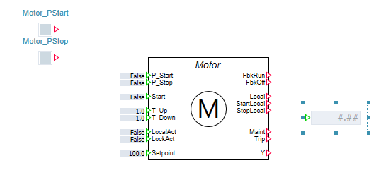
Insert Motor
Go to Drives>Motor and Select Motor.

Drop it into your Chart.

A motor simulation block is inserted into your chart now.

Function test
Let’s Test the Motor Block first.
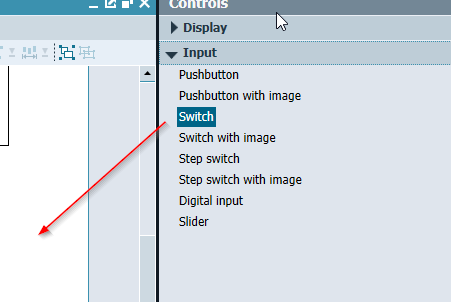
Add Push Button
Click the Controls tab on your right side.
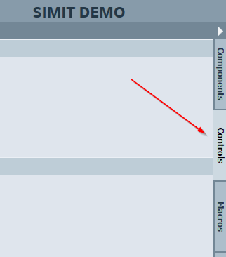
Go to Controls>Input and select the Pushbutton.

Drop it into your chart sheet.

Although it is not like a button, this small rectangle is a push button.
Press=True,release = false.

Edit-Show names
It is better to show what this button is using for.
Select the button>General>Check the Show names box.

The name is shown now.

Edit-Name
Then we can edit the text.
Go to General>Name and enter a meaningful name.

Done!Now we have Motor_PStart and Motor_PStop.

Add Slider
I will add 3 Sliders to adjust the Ramp up/down time and Speed Setpoint
Go to Controls>Input and Drop the Slider to your chart..

Sliders are inserted into your chart.

Edit-Start/End Value
Start/End value is the limit of your slider.

Edit-Increment
Increment is the value change of 1 slide.

Edit-Default Value
Default value is also very convenient for you, a default value while simulation is started.

Add Digital display
Finally, I will add a Digital display to monitor the Block output.
Go to Controls>Display and Drop the Digital display into your chart.

Digital display is inserted.
Linking
Now we can link all these variables to your Motor Simulation Block.

Testing
As below, the Motor will output the Setpoint while P_Start is changed from False to True, and the ramp-up/ramp-down times are taken into account.

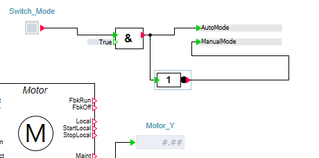
Add Mode
The title of this tutorial is using SIMIT with TwinCAT, Right?
2 Modes are defined here, Manual = Local operation in SIMIT, Auto=Remote operation from TwinCAT.
Manual Mode is triggered if the switch is turned on.
Auto Mode is triggered if the switch is turned off.
Add Connector
Go to Basic components>CONNECTORS and add 2 connectors.

There is a “name” property here.Actually it is a “Variable Name”.
For example, your connector name is Connector#1 and set it to some values in the simulation. This value can be re-use again in other charts/blocks.
In a word, It is just a variable.

variables are inserted into your chart.

Add AND Gate
Go to Connectors>STANDARD>BinaryBasic and Drop the AND object to your chart.

AND Gate is inserted.

Add NOT Gate
Do the same for the NOT gate.

The NOT gate is inserted also.

Add Switch
Now we will insert a switch in your chart.
Open the Controls tab.

Go to Controls>Input and drop the switch into your chart.
Create Mode Change Flow
Here is the flow for the mode control.
Add Push Button interlock
Now we can add the interlock for the P_Start and P_Stop, with a AND gate of Manual Mode.

Testing
The motor can only operate while manual mode is activated.

Add AutoStart signal
We will create an AutoStart signal that is assigned to the “Start” connector of the Motor Simulation block. This Start Signal is for TwinCAT only.
STW1.0 is used here,and we need to convert it from DWord to Byte then from byte to Bit.
Add DWord2Byte
Add the DWord2Byte Blocks to your Chart.

DW is the input and the block will split 4 bytes output.

Add Byte2Bit
Add the Byte2Bit Block to your Chart

A byte input is required in this block and output is 8 bit.

Add Control Flow
Finally, Assign the STW1 as the input of DWord2Byte, then assign the Byte0 data as the intput of Byte2Bit block, then use the “0” output to the start signal of Motor Block with an Auto Mode interlock.

Add new Chart
Too many Logic are added in our chart , It is the time to split your logic to different depending on the function.
Go to Charts>New chart.

The Mode operation and Manual Start/Stop/Setpoint will move to this new chart.

Add Auto Start Signal again
Auto Start Signal will also place to the new chart.

And do not forget to connect the “AutoStart” Signal to the Start parameter.

Add Auto setpoint
Auto setpoint is created to receive the Speed command from TwinCAT.
The Profiedrive1_NSoll connector is added and assigned to the NSoll output.

Analog Selector is inserted to split the setpoint assignment between Manual mode and auto mode.
If input is 0,a Manual setpoint from the slider is used.
If input is 1,Auto setpoint from TwinCAT is used.

Do not forget to Assign the MotorSetpoint connector to the Setpoint parameter of the Motor Block.

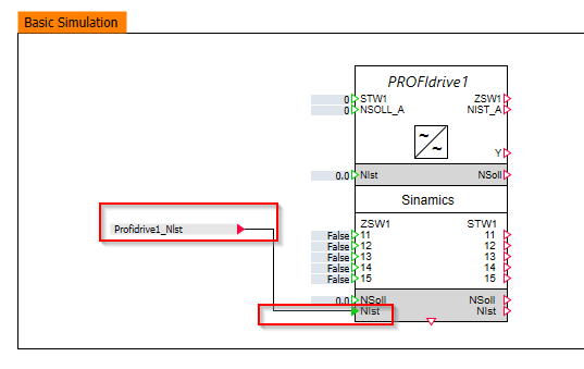
Add Feedback to Profidrive block
Feedback speed is added to simulate a “ramp up/down” function.
The ramp up/ramp down is controlled by a motor simulation block.
Profidrive1_NSoll is the speed command from Simulation Block>Div to Reference Speed and multiple 100.0 – a Scaled value from 0-100%
And Also the current speed is calculated by [Output Y /100.0 *Reference Speed] to scaled the current speed From 0 to reference speed.

And We will assign the Profidrive1_Nlst to your SImulation Block.
Flow
Here is the Control Chart that we created.
Profidrive1_Sim is the chart for the Main Simulation.

System chart is the logic for the Mode operation,Start/Stop and the Speed setpoint.

TwinCAT Side
Configure OPC-UA Client
Function Block – FB_ProfiDrvie1
This Function Block is the Main part of the ProfiDrive1 Control.
OPCUA-Client is used here, but you can change it to 4 words data in the real-application.
VAR_INPUT
| VAR_INPUT iRefHMI :REFERENCE TO DUT_ProfiDrive1_HMI; ir32AutoSpeedCmd :REAL; ibReset :BOOL; iMode :DUT_Mode; END_VAR |
| Name | Type | Description |
| iRefHMI | REFERENCE TO DUT_ProfiDrive1_HMI | The HMI Interface |
| ir32AutoSpeedCmd | REAL | Setpoint in Auto Mode |
| ibReset | BOOL | 1=Reset the error |
| iMode | DUT_Mode | The current mode – Auto/Manual |
VAR
STW1,NSOLL_A,ZTW1,NIST_A are defined as process IO. Please assign them to each ProfiDrive Interface.
| VAR STW1 AT %Q* :uDUT_STW; NSOLL_A AT %Q* :LINT; ZTW1 AT %I* :uDUT_ZSW; NIST_A AT %I* :LINT; OPCUA_Client :DUT_OPCUA_Client; RefIsVaild :BOOL; r32RefSpeed :REAL; w16Fault :WORD; w16Warning :WORD; TON :TON; END_VAR |
PROGRAM
Here is the program inside the Function block.
- Init the OPC-UA Connection
- Check if the HMI Ref is valid or not
- Enable the Drive
- Reset operation
- Fault Detection
| // OPCUA_Init(); // CheckRef(); // TON(IN:=OPCUA_Client.Status.Connected AND NOT fault,PT:=T#1S); Enable(mbEnable:=TON.Q); // Reset(mbReste:=ibReset); //Fault Fault00_FromDrive(); Fault01_RefSpeedErr(); //Warning Warning00_FromDrive(); |
Method
CheckRef
The runtime will be stopped if a invalid reference is passed inside, so __ISVAILDREF() is a function to check if the Reference is correct or not.
| METHOD CheckRef : BOOL RefIsVaild:=__ISVALIDREF(iRefHMI); |
Enable
The Enable Signal is activated from HMI.
| METHOD Enable : BOOL VAR_INPUT mbEnable:BOOL; END_VAR IF mbEnable AND RefIsVaild THEN STW1.stSTW.b00Off1:=iRefHMI.PB.bOFF1; END_IF; |
Fault00_FromDrive
The error that is received from ProfiDrive is detected here.
| METHOD Fault00_FromDrive : BOOL IF ZTW1.stZSW.b03FaultActive THEN w16Fault.0:=TRUE; END_IF |
Fault01_RefSpeedErr
Fault01 is the error if the Reference speed is <=0.
| METHOD Fault01_RefSpeedErr : BOOL IF RefSpeed <=0.0 THEN w16Fault.1:=TRUE; END_IF |
FB_Init
Activate the basic configuration of Profidrive.
| METHOD FB_init : BOOL VAR_INPUT (* if TRUE, the retain variables are initialized (warm start / cold start)*) bInitRetains : BOOL; (* if TRUE, the instance afterwards gets moved into the copy code (online change)*) bInCopyCode : BOOL; END_VAR STW1.stSTW.b01Off2:=TRUE; STW1.stSTW.b02Off3:=TRUE; STW1.stSTW.b03EnableOperation:=TRUE; STW1.stSTW.b04DisableRFG:=TRUE; STW1.stSTW.b05EnableRFG:=TRUE; Stw1.stSTW.b06EnableSetpoint:=TRUE; Stw1.stSTW.b10ControlByPLC:=TRUE; |
Hmi
Transfer the status to HMI.
| METHOD Hmi : BOOL IF RefIsVaild THEN iRefHMI.PL.i64RawDataZTW:=ZTW1.stZSW; iRefHMI.PL.i64RawDataSTW:=STW1.stSTW; iRefHMI.PL.i64RawData_NIST_A:=NIST_A; iRefHMI.PL.i64RawData_NSOLL_A:=NSOLL_A; iRefHMI.PL.bFault:=Fault; iRefHMI.PL.bWarning:=Warning; iRefHMI.PL.bReady:=Ready; iRefHMI.PL.r32ActualSpeed:=RawSpeed2Real(raw:=NIST_A); iRefHMI.PL.OPCUAControl:=OPCUA_Client.Control; iRefHMI.PL.OPCUAStatus:=OPCUA_Client.Status; END_IF |
OPCUA_Init
Write-Enable is only True if TwinCAT is connected to the OPC UA Server.
| METHOD OPCUA_Init : BOOL IF OPCUA_Client.Status.Connected THEN OPCUA_Client.Control.Write_Enable:=TRUE; ELSE OPCUA_Client.Control.Write_Enable:=FALSE; END_IF |
r32Speed2Raw
Convert the Speed from 0-100% to 0-16384.0
| METHOD r32Speed2Raw : LINT VAR_INPUT mr32Setpoint:REAL; END_VAR r32Speed2Raw:= REAL_TO_LINT( (mr32Setpoint/100.0)*16384.0) ; |
RawSpeed2Real
Convert the speed from 0-16384. to 0-100%.
| METHOD RawSpeed2Real : REAL VAR_INPUT raw:LINT; END_VAR RawSpeed2Real:= (LINT_TO_REAL (raw)/16384.0) *100.0; |
Reset
Error Reset.
| METHOD Reset : BOOL VAR_INPUT mbReste:BOOL; END_VAR STW1.stSTW.b07Ack:=mbReste OR (RefIsVaild AND iRefHMI.PB.bReset) ; w16Fault:=0; w16Warning:=0; |
Run
The program to write the Speed setpoint to drive depends on the Ready Condition and Mode.
| METHOD Run : BOOL IF NOT Ready THEN NSOLL_A:=0; END_IF; IF Ready THEN IF RefIsVaild AND iMode = DUT_Mode.Manual THEN NSOLL_A:=r32Speed2Raw(mr32Setpoint:=iRefHMI.PB.r32SpeedSetPoint); ELSIF iMode= DUT_Mode.Auto THEN NSOLL_A:=r32Speed2Raw(mr32Setpoint:=ir32AutoSpeedCmd); END_IF; END_IF |
Stop
Write 0 to speed set-point.
| METHOD Stop : BOOL NSOLL_A:=0; |
Warning00_FromDrive
The warning detection from Drive.
| METHOD Warning00_FromDrive : BOOL IF ZTW1.stZSW.b07AlarmActive THEN w16Warning.0:=TRUE; END_IF |
Proprety
ActSpeed
Get the Actual Speed.
| PROPERTY ActSpeed : REAL |
CmdSpeed
Get the Command Speed.
| PROPERTY CmdSpeed : REAL |
Fault
Get the Fault From Function Block.1=Fault.
| PROPERTY Fault : BOOL |
Ready
Get the Ready Conditon.1=Ready.
| PROPERTY Ready : BOOL |
RefSpeed
Get and Set the Reference Speed. A very important parameter and must match with SIMIT.
| PROPERTY RefSpeed : REAL |
Warning
Get the Warning From Function Block.1=Warning
| PROPERTY Warning : BOOL |
DUT
DUT_Mode
| {attribute ‘qualified_only’} {attribute ‘strict’} TYPE DUT_Mode : ( enum_member := 0 ,Auto:=1 ,Manual:=10 ); END_TYPE |
DUT_STW
Please reference the below tutorial to get more information.
| TYPE DUT_STW : STRUCT b00Off1 :BIT; b01Off2 :BIT; b02Off3 :BIT; b03EnableOperation :BIT; b04DisableRFG :BIT; b05EnableRFG :BIT; b06EnableSetpoint :BIT; b07Ack :BIT; b08Spare :BIT; b09Spare :BIT; b10ControlByPLC :BIT; b11Direction :BIT; b12 :BIT; b13 :BIT; b14 :BIT; b15 :BIT; _noused :ARRAY[0..2]OF INT; END_STRUCT END_TYPE |
uDUT_STW
Use union data type to define the STW and LINT for Process I/O assignment.
| TYPE uDUT_STW : UNION STW:LINT; stSTW:DUT_STW; END_UNION END_TYPE |
DUT_ZSW
Please reference the below tutorial to get more information.
| TYPE DUT_ZSW : STRUCT b00Ready2SStart :BIT; b01Ready :BIT; b02OperationEnable :BIT; b03FaultActive :BIT; b04Off2InActive :BIT; b05Off3InActive :BIT; b06LockOut :BIT; b07AlarmActive :BIT; b08SpeedDeviation :BIT; b09MasterControlRequested :BIT; b10SpeedReached :BIT; b11 :BIT; //manufactor-define b12 :BIT; //manufactor-define b13 :BIT; //manufactor-define b14 :BIT; //manufactor-define b15 :BIT; //manufactor-define _noused :ARRAY[0..2]OF INT; END_STRUCT END_TYPE |
uDIT_ZSW
Use union data type to define the ZSW and LINT for Process I/O assignment.
| TYPE uDUT_ZSW : UNION ZSW:LINT; stZSW:DUT_ZSW; END_UNION END_TYPE |
DUT_ProfiDrive1_HMI_PB
The Command of HMI.
| TYPE DUT_ProfiDrive1_HMI_PB : STRUCT bOFF1:BOOL; r32SpeedSetPoint:REAL; bDriveON:BOOL; bDriveOFF:BOOL; bReset:BOOL; END_STRUCT END_TYPE |
DUT_ProfiDrive1_HMI_PL
The Status display of HMI.
| TYPE DUT_ProfiDrive1_HMI_PL : STRUCT bFault :BOOL; bWarning :BOOL; bReady :BOOL; i64RawDataSTW :DUT_STW; i64RawData_NSOLL_A :LINT; i64RawDataZTW :DUT_ZSW; i64RawData_NIST_A :LINT; r32ActualSpeed :REAL; OPCUAStatus :OpcUaDeviceStatus; OPCUAControl :OpcUaDeviceControl; END_STRUCT END_TYPE |
DUT_ProfiDrive1_HMI
The “Group” of the HMI.
| TYPE DUT_ProfiDrive1_HMI : STRUCT PB:DUT_ProfiDrive1_HMI_PB; PL:DUT_ProfiDrive1_HMI_PL; END_STRUCT END_TYPE |
DUT_OPCUA_Client
The stauts and Control for the OPC-UA Client.
| TYPE DUT_OPCUA_Client : STRUCT Status AT %I*:OpcUaDeviceStatus; Control AT %Q*:OpcUaDeviceControl; END_STRUCT END_TYPE |
HMI
Here is the HMI for the Main Control.
We can view all the Control Word in Tab1.

In Tab, Status is shown.

In tab3, OPC UA client status is displayed.

MAIN
VAR
| PROGRAM MAIN VAR Drive1 :FB_ProfiDrvie1; Drive1Hmis :DUT_ProfiDrive1_HMI; bEnable :BOOL; r32ActSpeed :REAL; r32CmdSpeed :REAL; hmiMode :DUT_Mode; END_VAR |
PROGRAM
| Drive1.RefSpeed:=3000.0; Drive1( iRefHMI:=Drive1Hmis ,iMode:=hmiMode ); r32ActSpeed:=Drive1.ActSpeed; Drive1.Run(); Drive1.Hmi(); |
Result
Source Code Download
https://github.com/soup01Threes/TwinCAT3/blob/main/TwinCAT%20Project_withSIMIT_Prodrive1.zip
コメント
Hello brother
Thank you for this tutorials
I wanna kindly ask you if you can share SIMIT Software please and I wanna know which SIMIT version you use ?
I installed DEMO SIMIT V8.0 and TIA PORTAL V13.0 AND PLCSIM V5.4 ( because I have a weak laptop hahaha ) and when I try to drag and drop ProfiDrive model it tell me that it protected by a pasword ! so I can not use Prodfidrive modules in my version
I will be so greatfull if you help me and thank you again !