In this tutorial I will explain how to control a Siemens drive.In the Last post,we used a software that was provided by Siemens that called “Starter” – directly control the drive from this commissioning tool.
This is very important for this step – you can check if there are any problems on the hardware side and split the commissioning tasks in small pieces.
After you can control the drive from the Commissioning tool directly, we can use User Program to control your drive.
Reference Link

SINA_SPEED and Telegram1
What is Telegram? Siemens’s Telegram is a “format” to communicate in the Profidrive Protocol.There are so many Telegrams but not Telegram1:
- Telegram1
- Telegram111
- Telegram30(for profisafe)
- Free Telegram(User defined)
Telegram111 can be used in the Sinamics Basic Position features, Telegram1 can be used in the simple speed control.It is dependent on your applications.
Thanks to Siemens for providing some libraries for these functions.
- SINA_SPEED for speed control
- SINA_POS for positioning
- SINA_PARA to get/set the parameters inside the drives.
Library Installation
Please download the library with your TIA Version.

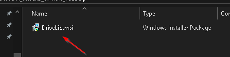
After unzip, DriveLib.msi is found.
Double click to install it.
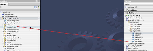
After the installation,open your TIA and go to Library>Drive_Lib_S7_1200_1500>Master copies>03_SINAMICS>SINA_SPEED, drop it into your project.
Hardware Configuration
Now we can create the hardware configuration. G120 and Telegram1 are used in this tutorial.
TIA
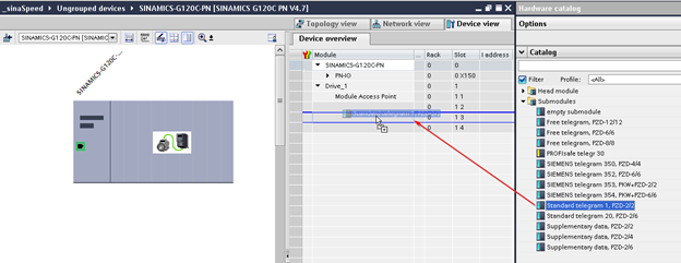
Insert G120 into your Project.
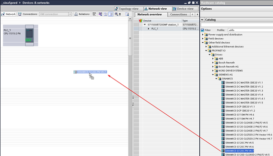
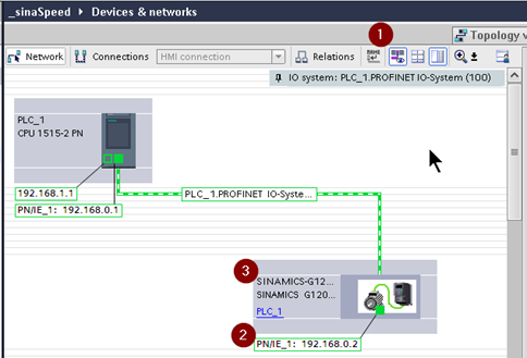
Click the “Not assigned” to assign your drive into the profinet network.

Enter the IP and Device name of G120.
Drop the Telegram1 into your drive.
Starter
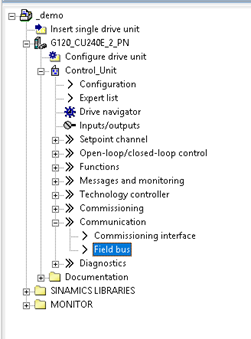
Open the Starter Software and go to the Field bus object.
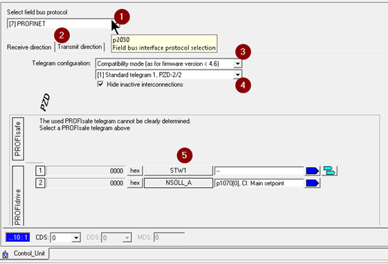
1.Select the Field bus protocol:Profinet is our selection.
2.Send/receive data that you are configuring.(View from the Drive)
3.Choose Compatibility Mode.
4.Telegram Configuration.Telegram 1 is used in this tutorial.
5.Configuration of your Telegram.
Telegram 1
Here is the basic structure of Telegram1.
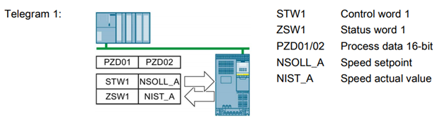
STW1
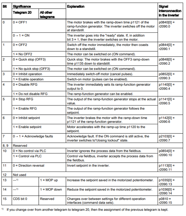
ZSW1

Read more
we can click the “STW1” box to view the telegram configuration.
in the online mode, the current signal is shown in this popup also.
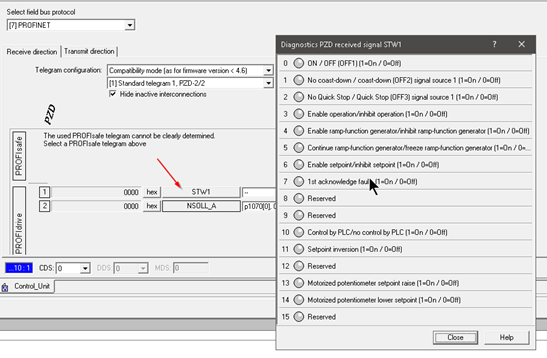
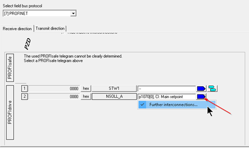
NSOLL_A is connected to p1070[0]. Click the blue box>Further interconnections to see the detail.
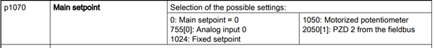
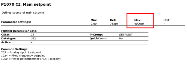
P1070[0] is the speed setpoint.

Reference to the Manaul:
Let’s see the data that transfer from Drive to PLC.
1.Choose the transmit direction tab.
2.Click ZSW1

ZSW1 is connected to r2053[0].
r=read only
w=read or write
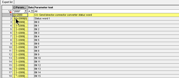
It means that the data from r2089 is directly transferred to r2053[0].

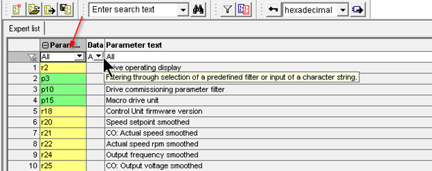
Enter 2089 in the Parameter field.
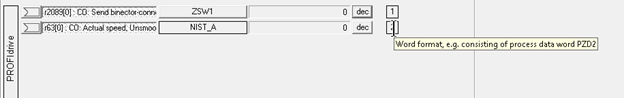
Finally.NIST_A is connected to r63[0]. It is a word format, PZD2.
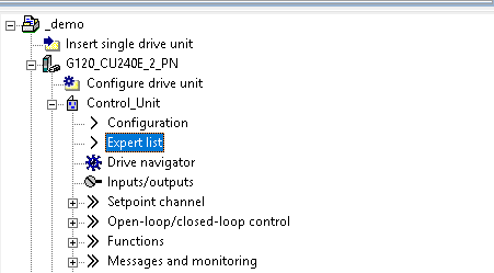
r2089 can be viewed in the expert list also.
The status can be viewed also by Diagnostics>Interconnections.
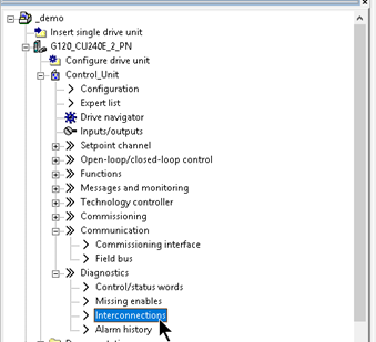
All status can be viewed here.

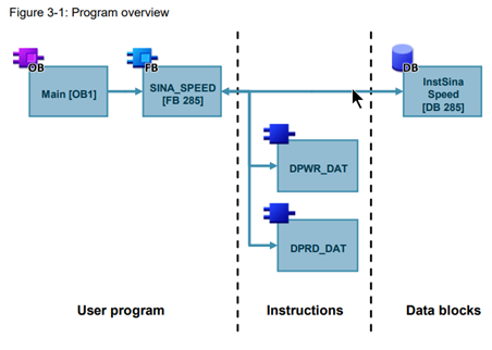
Program
Here is the program structure of SINA_SPEED.
DPWR_DAT and DPRD_DAT are called inside to implement the profinet communication.
Because It is a function block, Instance DB is necessary.
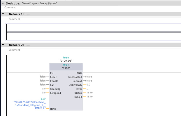
SINA_SPEED
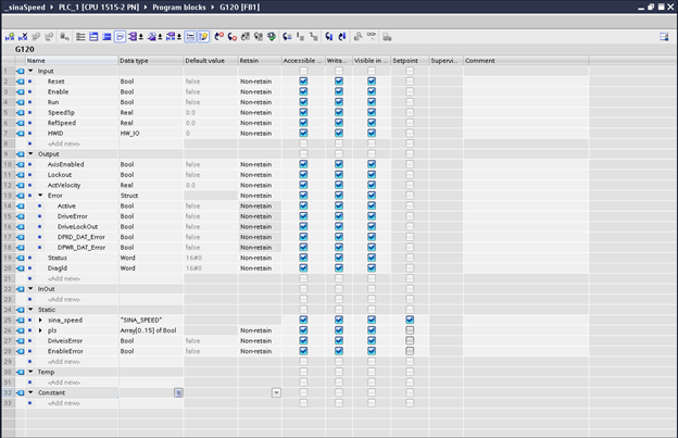
This is the Function Block of SINA_SPEED, i will explain all the in/out parameters.
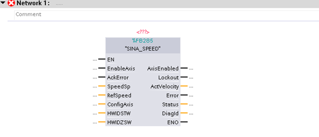
Input
- EnableAxis(Bool)
- Start/Stop the Drive(Assigned to Control Word Bit0)
- AckError(Bool)
- Rest the Drive Error(Assigned to Control Word Bit7)
- SpeedSp(Real)
- Speed Setpoint(1/min)
- RefSpeed(Real)
- The reference speed of the motor(must be matched to p2000)
- ConfigAxis(Word)
- Configure the Control word(p2090)
- Bit1:OFF2
- Bit2:OFF3
- Bit3:Enable Operation
- Bit4:Enable Ramp-Function Generator
- Bit5:Continue Ramp up Function Generator
- Bit6:Enable Speed Setpoint
- Configure the Control word(p2090)
- HWIDSTW
- The hardware ID of your Drive
- HWIDZTW
- The hardware ID of your Drive
Output
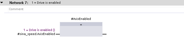
- AxisEnabled(Bool)
- Drive is Enabled or not
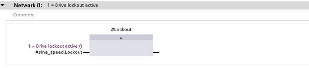
- Lockout(Bool)
- Drive is Lock or not
- ActVelocity(Real)
- Actual Velocity
- Error(Bool)
- Drive is error or not
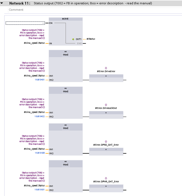
- Status(Word)
- 16#7002=Normla
- 16#8401=Drive is error
- 16#8402=Drive had problem
- 16#8600=Error in DPRD_DAR
- 16#8601=Error in DPWR_DAT
- Diagld(Word)
- The status of communication error
Implementation
Now we will create some sample programs.
Let’s Create a function Block that is named G120.
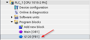
Call it in OB1.
Interface
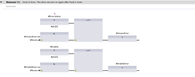
NTW1:Drive Reset

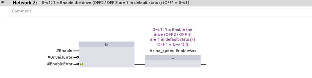
NTW2:Drive Enable
A reset operation is needed to re-enable your drive while an error is occurring.
NTW3:Ref Speed

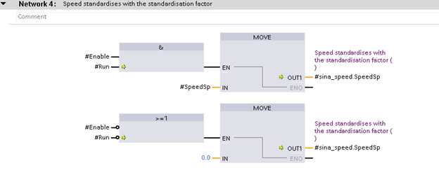
NTW4:Write the Speed setpoint
If the enable signal is off or the run command is off, 0 is always output.
NTW5:Transfer the HWID
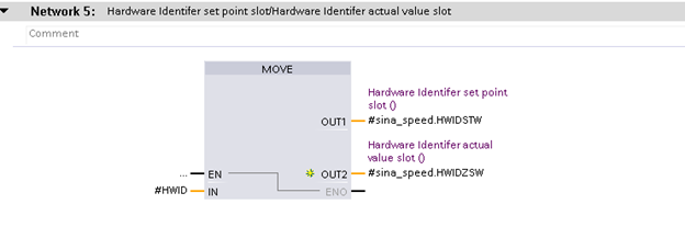
NTW6:Call the SINA_SPEED

NTW7:Drive is Enabled or not
NTW8:Drive had problem or not
NTW9:Current speed

NTW10:Flag for Drive Error

NTW11:Output the Error Status
NTW12:Get the Error status while communication fault

NTW13:The Error Flag reset operation
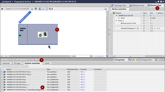
How to check the HWIO?
Open the Deview view and click the G120 Drives.
The HWIO is shown in System constants>XXXX_Standard_Telegram_1XX.
Bouns1- Inside SINA_SPEED
SINA_SPEED is implemented in SCL Language or splitted to 4 parts.(In my view)
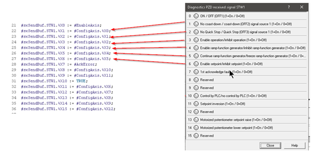
- Part1:Line20-26
- the code to Assign the ConfigAxis,EnableAxis,AckError input parameters to STW.
- Part2:Line38-55
- the code to Assign the speed setting
- Part3
- The code to send the data by profinet.
- Par4
- Error operation,get data from Drive

Part1
EnaleAxis,Ackerror is Assigned to Stw1.%X0 and STW1.%X7.
STW1.%X10 is the bit for the PLC Control Request.
We implemented the control by PLC, sure this device should be true.

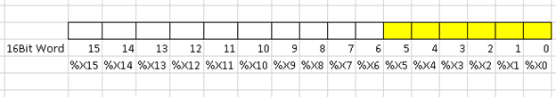
Here is the map from %X0 to %X15.

If 16#07 is written into the 16bit word..
16#07=1+2+4, %X0,%X1 and %X1 is True.
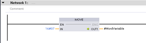

And Also, If we Write the %X0,%X1 and %X2 to Ture, the 16bit word ‘value is 16#07.
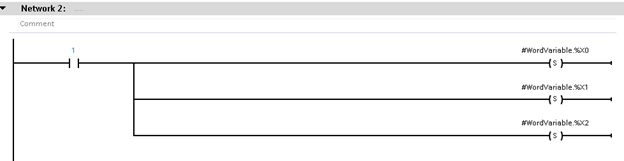
The value of Config input parameter is 16#3F.
It means that from %X0 to %X5 are true.
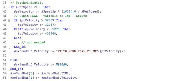
Part2:Speed setting
- Line39
- used to check if the RefSpeed is 0 or not because we can not divide 0 in any program language.
- Line40
- 16384 =4000Hex , we can check p1070 in the starter and Manual, Max=4000hex=16384
A Scaling is implemented in here.If RefSpeed is 2500, and your speed setpoint is 1300,
The Value that output to the Drive is:
SpeedSp*(16384.0/RefSpeed)=1300x(16384/2500)=8519.
- 16384 =4000Hex , we can check p1070 in the starter and Manual, Max=4000hex=16384
- Line42-48
- Check if the speed setpoint is inside the range or not.
- Line49
- Change the data type to word and move to buffer.
- Line51-52
- If Refspeed parameter is <=0, write 0 to the speed setpoint
- Line54-55
- Move the STW1 and Speed setpoint to the transfer buffer.

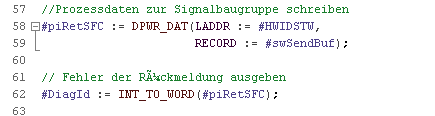
Part3 – Profinet Data Transfer
The code to Exchange the Profinet Data, reference from HWID.
Part4-Data get from Profinet
I will split 4 parts to explain it.
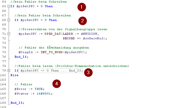
Part1
Check the result of profinet data exchange function is 0 or not,
0=Normal.

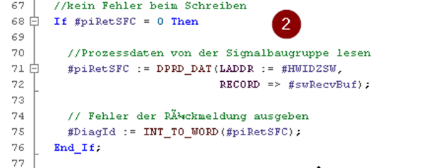
Part2
If there is no error from piRetSFC, the program will execute the DPRD_DAT function to get the data from drive by profinet, and change the data type from Word to int, transfer to Diagld.
Part3
All receive buffer force to 0 if DPRD_DAT had error.

The data that receive from DPRD_DAT Function are transferred to sxRecvBuff.
ZSW1 is the index 0 of the word,
Velocity is the index 1 of the word.
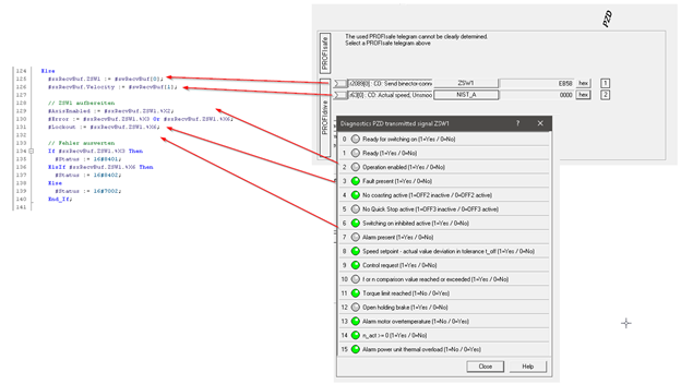
Line155-161 is the code to check if the RefSpeed is 0 or not.
And Scale back the data to current speed.
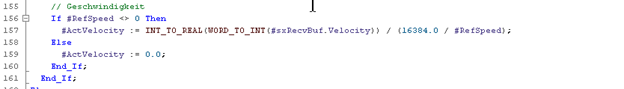
Actual Speed is forced to 0 iF Refspeed is 0.
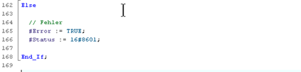
Line 162-168 is the error operation.
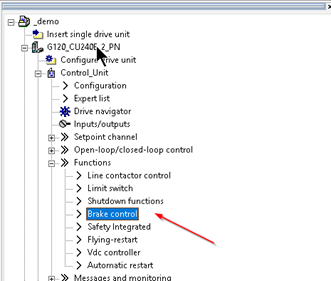
Bouns2-Brake
Go to DriveUnit>Control_Unit>Functions>Brake control.
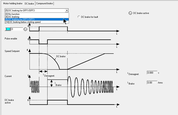
Select the Motor holding brake to 1.(holding brake acc. To sequence control)
p1215 will be

Here is the time chart.

Change the Brake setting in here also.
コメント
Hello sir
I like your discussions, could you send me sina_speed scl codes please.
Dear,
You can download from Siemens SIOS!