In this tutorial I will show you how to simulate the telegram111 in simit and implement the control program in TwinCAT Side.
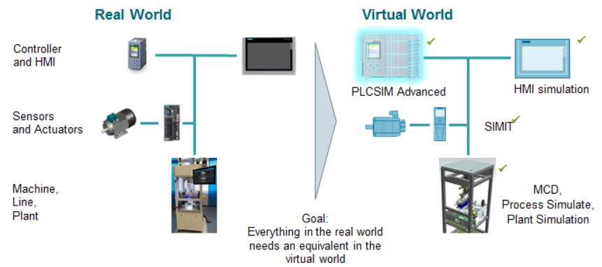
But before I start, I would like to ask a question – what is the goal of simulation?
My answer will be to implement the machine in the virtual world and the same as in the real world.So,the main point of virtual commissioning is how “real” that you can simulate.
SIMIT will release more libraries in the future to support complex Profidrive telegram – And in this post Telegram111 is used.
By using SIMIT we can decrease the commissioning time on site/debug time but also for the Training purpose with a new programmer or operator.
Please Support some devices for my blog
https://www.amazon.jp/hz/wishlist/ls/H7W3RRD7C5QG?ref_=wl_share
Download
Please access this link to download the library.

Configration
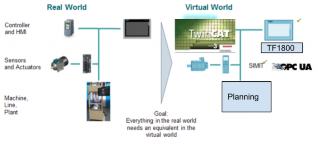
Here is my configuration. I will replace the PLCSIMAdv with TwinCAT3 ,using TF1800 as HMI Display.An OPC-UA Server is configured on the SIMIT side and TwinCAT TF6100 is used to access this Server.
Telegram111?
Telegram 111 is a standard telegram from Siemens to provide a bridge between your drive and PLC by using the EPOS blocks to control the Drive.
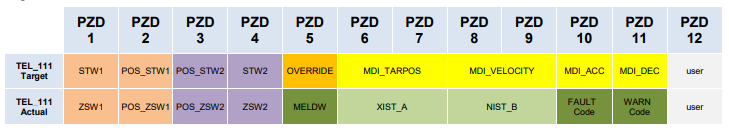
Telegram 111 is very similar to Telegram110 but the message frame is larger – 12 words of PZDs are used.
Telegram 111 provided these features:
- Basic positioner for servo positioning
- 32 bit Position data
- 32 bit Speed data
- 16 bit Acceleration and Deceleration data
- signs of life monitor
- Cyclic exchange of Error code warning code
EPOS Operation Flow
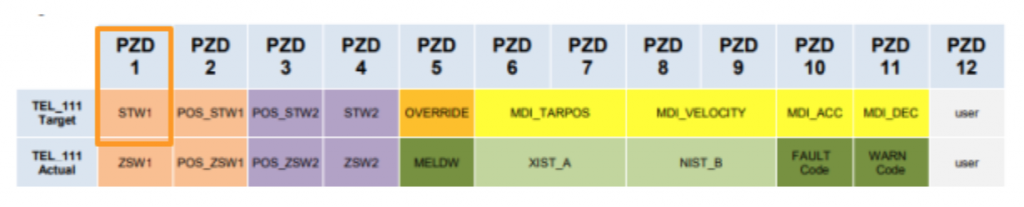
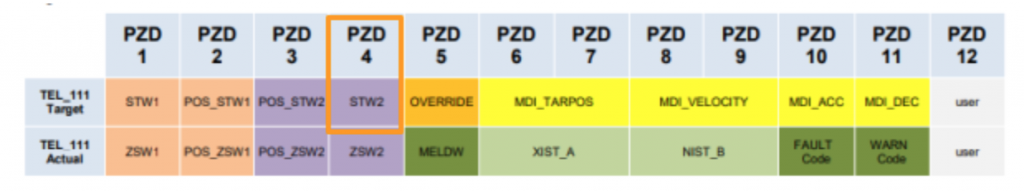
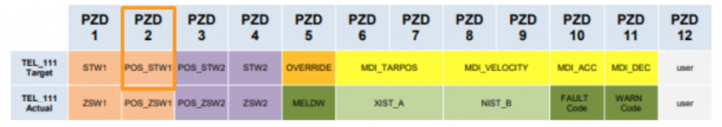
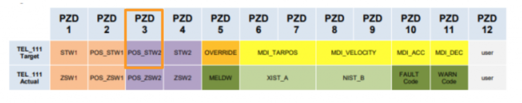
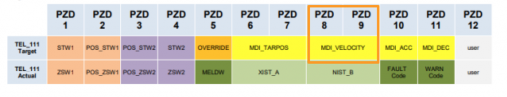
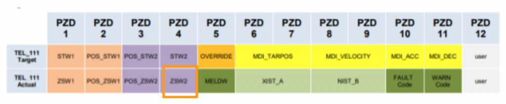
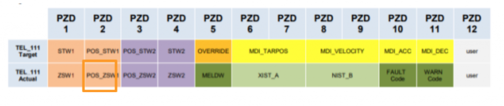
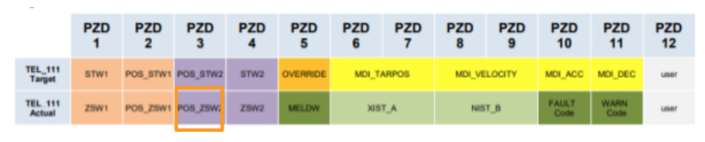
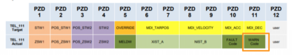
TEL_111 Target
I will explain the structure of Telegram111 in here.
STW1
| Bit | Device | Description |
| 0 | Off1 | ON command0=OFF1 is activated 1=ON |
| 1 | Off2 | 0=Off2 is activated |
| 2 | Off3 | 0=Off3 is activated |
| 3 | Enc | Inverter is activated |
| 4 | RejTrvTask | 0=Travering Records is used1=MDI Discard travsering task is used |
| 5 | IntMStop | 1=not immediately stopped |
| 6 | TrvStart | Traversing Task execution |
| 7 | AckFault | Fault Reset |
| 8 | Jog1 | Jog Signal1 |
| 9 | Jog2 | Jog Signal2 |
| 10 | LB | Life Bit(1=Control By PLC) |
| 11 | RefStart | Start to Homing |
| 12 | Bit12 | |
| 13 | Bit13 | External block Change (0>1) |
| 14 | Bit14 | |
| 15 | Bit15 |
STW2
| Bit | Device | Description |
| 0 | DDSBit0 | Drive data set bit0 |
| 1 | DDSBit1 | Drive data set bit1 |
| 2 | DDSBit2 | Drive data set bit2 |
| 3 | DDSBit3 | Drive data set bit3 |
| 4 | DDSBit4 | Drive data set bit4 |
| 5 | GlbStart | Global start |
| 6 | ReslComp | Reset the Speed Controller’s I-Component |
| 7 | ActPrkAxis | Parking axis Enable |
| 8 | TrvFixedStp | Moving to Fixed endstop |
| 9 | GlbTrgCom | Global Trigger Command |
| 10 | Bit10 | |
| 11 | MotSwOver | Motor Switchover |
| 12 | MsZykBit0 | Master sign of life bit0 |
| 13 | MsZykBit1 | Master sign of life bit1 |
| 14 | MsZykBit2 | Master sign of life bit2 |
| 15 | MsZykBit3 | Master sign of life bit3 |
POS_STW1
| Bit | Device | Description |
| 0 | TrvBit0 | Selection Bit 0 |
| 1 | TrvBit1 | Selection Bit 1 |
| 2 | TrvBit2 | Selection Bit 2 |
| 3 | TrvBit3 | Selection Bit 3 |
| 4 | TrvBit4 | Selection Bit 4 |
| 5 | TrvBit5 | Selection Bit 5 |
| 6 | Bit6 | |
| 7 | Bit7 | |
| 8 | MdiTyp | Type of positioning0=Relative positioning1=Absolute positioning |
| 9 | MdiPos | The axis rotation of MDI operation while axis is in rotate axis1=Positive |
| 10 | MdiNeg | The axis rotation of MDI operation while axis is in rotate axis1=Negative |
| 11 | Bit11 | |
| 12 | MdiTrTyp | The signal Type of MDI Task execution0=rise edge1=Setpoint change |
| 13 | Bit13 | |
| 14 | MdiSetup | MDI Mode0=positioning1=Setup |
| 15 | MdiStart | 1=MDI Operation Mode |
POS_STW2
| Bit | Device | Description |
| 0 | TrkMode | Tracking Mode start |
| 1 | SetRefPt | set the Reference Point |
| 2 | ActRefCam | Enable the Reference Cam |
| 3 | Bit3 | Enable the Fixed stop |
| 4 | Bit4 | |
| 5 | JogInc | 0=continuous Jog1=Jog action from parameters |
| 6 | Bit6 | |
| 7 | Bit7 | |
| 8 | RefTyp | Homing method0=Reference Point approach1=Passive (on-the-fly) homing |
| 9 | RefStDi | The direction to start find the Reference point0=Positive1=Negative |
| 10 | RefInpS | Passive (on-the-fly) homingのSignal source0=Probe 1 Enable1=Probe 2 Enable |
| 11 | RefEdge | Passive homing detection0=Rise edge1=Fall edge |
| 12 | Bit12 | |
| 13 | Bit13 | |
| 14 | SftLimAct | Software Limit Enable |
| 15 | StpCmaAct | Stop Cam Enable |
OVERRIDE
The Override Speed.

MDI_TARPOS
The Target Command.

MDI_VELOCITY
The Target Velocity.
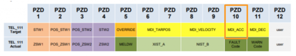
MDI_ACC
The Accelerate command.
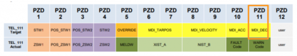
MDI_DEC
The Decelerate command.
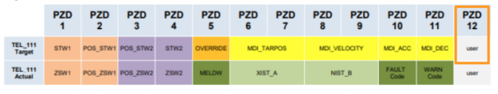
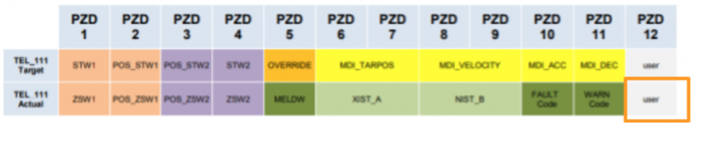
User
An Extend PZD for user-defined functions.
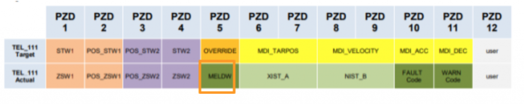
TEL_111 Actual
ZSW1
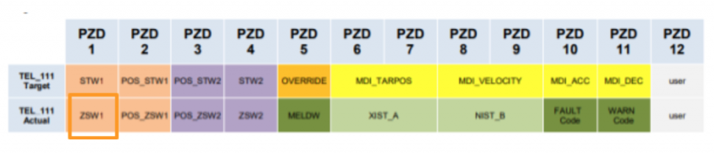
| Bit | Device | Description |
| 0 | RTS | 1=Power UP Ready |
| 1 | RDY | 1=Operation Readt |
| 2 | IOp | 1=Servo ON,The condition of EPOS |
| 3 | Fault | 1=Fault |
| 4 | NoOff2Act | 1=Off2 is not activated |
| 5 | NoOff3Act | 1=Off3 is not activated |
| 6 | PowInhbt | 1=Drive ON is not activated |
| 7 | Alarm | 1=warning |
| 8 | NoFlwErr | |
| 9 | LbCr | 1=request to control |
| 10 | TargPos | Target position is reached(This bit can be used in positioning) |
| 11 | RefPSet | Reference Point is set |
| 12 | TrvTskAck | The Traveling Block is enabled. |
| 13 | StndStill | 1=Drive is stoppedCurrent speed < Speed threshold3 |
| 14 | Accel | Drive is accelerating |
| 15 | Decel | Drive is decelerating |
ZSW2
| Bit | Device | Description |
| 0 | ActDDSBit0 | Drive data Set Bit0 |
| 1 | ActDDSBit1 | Drive data Set Bit1 |
| 2 | ActDDSBit2 | Drive data Set Bit2 |
| 3 | ActDDSBit3 | Drive data Set Bit3 |
| 4 | ActDDSBit4 | Drive data Set Bit4 |
| 5 | CmdActRelBrk | Release holding brake is enabled |
| 6 | TrqContMode | Torque Operating |
| 7 | ParkAxisAct | Parking axis |
| 8 | Bit8 | |
| 9 | GibTrgReq | Global Trigger Requesting |
| 10 | PulsEn | Received Pulse signal of Servo ON and Drive is Enabled |
| 11 | MotSwOverAct | Motor Data set switchover Active |
| 12 | SlvZykBit0 | Slave – Sign of life bit0 |
| 13 | SlvZykBit1 | Slave – Sign of life bit1 |
| 14 | SlvZykBit2 | Slave – Sign of life bit2 |
| 15 | SlvZykBit3 | Slave – Sign of life bit3 |
POS_ZSW1
| Bit | Device | Description |
| 0 | ActTrvBit0 | Activating Traveling Block Bit0 |
| 1 | ActTrvBit1 | Activating Traveling Block Bit1 |
| 2 | ActTrvBit2 | Activating Traveling Block Bit2 |
| 3 | ActTrvBit3 | Activating Traveling Block Bit3 |
| 4 | ActTrvBit4 | Activating Traveling Block Bit4 |
| 5 | ActTrvBit5 | Activating Traveling Block Bit5 |
| 6 | Bit6 | |
| 7 | Bit7 | |
| 8 | StpCamMinAct | Stop CAM Minus active |
| 9 | StpCamPlsAct | Stop CAM Plus active |
| 10 | JogAct | Jog mode is activated |
| 11 | RefAct | Reference mode is activated |
| 12 | FlyRefAct | On-the-fly homing is activated |
| 13 | TrvBlAct | Traversing Blocks mode is activated |
| 14 | MdiStupAct | MDI setup Mode is activated |
| 15 | MdiPosAct | MDI positioning mode is activated |
POS_ZSW2
| Bit | Device | Description |
| 0 | TrkModeAct | Tracking Mode is activated |
| 1 | VeloLimact | Speed Limit is reached |
| 2 | SetPSたt | Setpoint set |
| 3 | PrntMrkOut | Print mark outside outer window |
| 4 | FWD | Axis is forwarding |
| 5 | BWD | Axis is backwarding |
| 6 | SftSwMinAct | Software Limit min is activated |
| 7 | SftSwPlsAct | Software Limit plus is activated |
| 8 | PosSmCam1 | Current position <=Cam switch position 1 |
| 9 | PosSmCam2 | Current position <=Cam switch position 2 |
| 10 | TrvOut1 | Direct out 1 from Traversing block |
| 11 | TrvOut2 | Direct out 2 from Traversing block |
| 12 | FxStpRd | Fixed Stop reached |
| 13 | FxStpTrRd | Fixed stop clamping torque reached |
| 14 | TrvFxStpAct | Travel to fixed stop active |
| 15 | CmdAct | Traversing Task is activated |
MELDW
The status code of the drive.
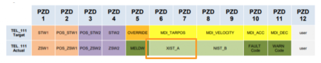
XIST_A
The current position.
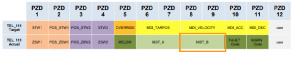
NIST_B
The current speed.
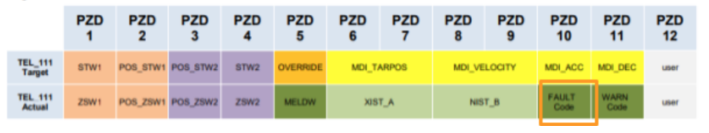
FAULTCode
The Fault code of the drive.
WARNCode
The Warning code of the drive.
User
An Extend PZD for user-defined functions.
Block EPOS_Tel111

State
There is a popup to show the current status of Simulation Block EPOS_Tel111.

Test with Jog
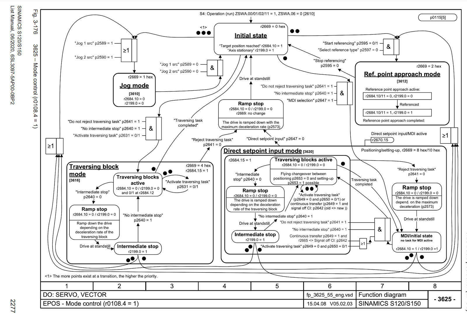
The Status is changed between 01>02>08>1E , from servo on to jog.
Please refer to the list manual to get more information.
Test
Servo ON From Panel
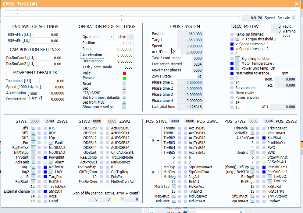
I will use the Control panel to start the drive one by one to check if the operation is correct or not.Start your Simit simulation and click the block.
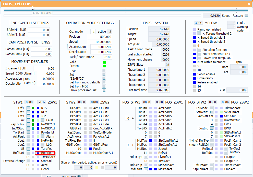
The below Screen is shown.We can force on/off the STW and view the zsw in here.
Let’s turn on the LB signal in STW1.
Click the small blue box near the LB signal.
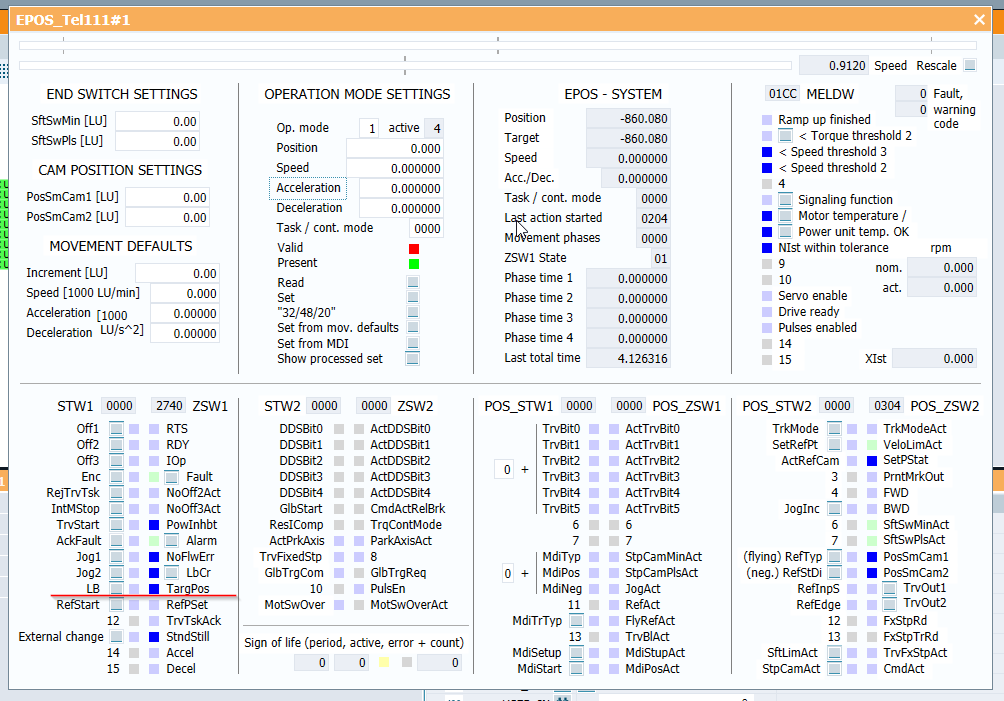
Now you can see the LB signal is changed to Light blue.
Please turn on the AckFault signal if any error occurs.

Now we can shift the servo condition to ready.
Turn on the Enc, ReqTrvTsk and IntMSop Signals.
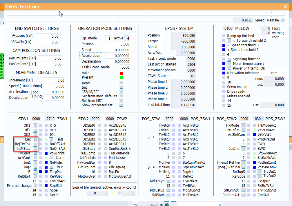
Then Turn on Off2,Off3.

Now The NoOFF2Act and NoOff3Act should be on.
And also RTS signals are ON.

Now we can Turn on the Servo.
Please Force on the Off1.
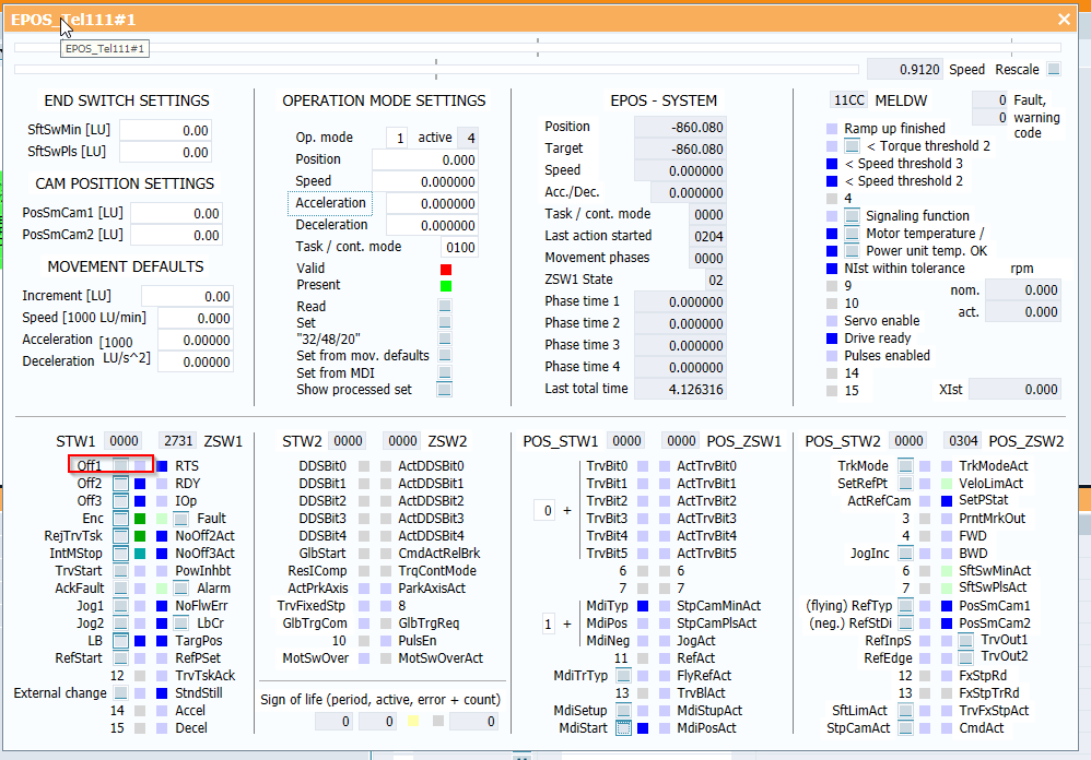
You can see RTS,RDY,IOp are True while the servo on operation is successful.

Absolute Positioning From Panel
After Servo on, we can try to execute an absolute positioning task.
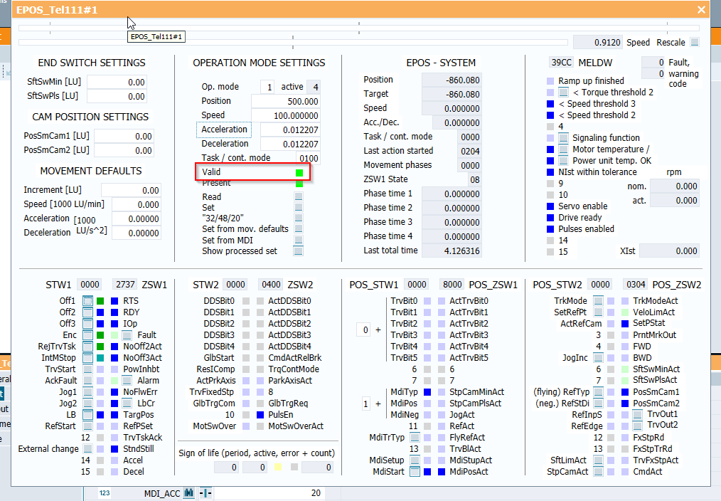
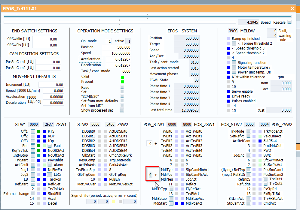
But there is a red lamp displayed in the operation mode settings field. It indicated that the command value is invalid.

Input Value “1” to the Midtyp of POS_STW1.
Now the drive will operate in absolute positioning, and Turn on the MdiStart to set the drive in Mdi Mode.
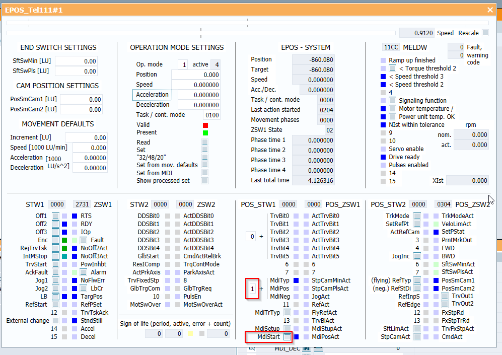
The reason for the red valid lamp is one of MDI_VELOCITY MDI_ACC MDI_DEC is 0.
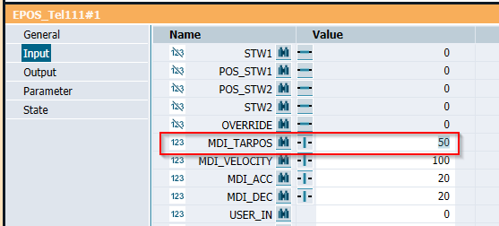
Let’s click the simulation block and go to propertery >input.
Let’s input some values of MDI_TARPOS /MDI_VELOCITY /MDI_ACC MDI_DEC.
Press the – button that is near the variable.
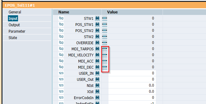
Just input some test value 😉
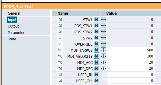
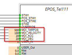
Then press the 123 button to make these values visible in the block.

Good. Values are changed.
The Valid LED is changed to Green ;)!
Before we execute the positioning task, setting a reference point is necessary.
There are so many homing methods but in this tutorial I will use the simple one – Directly set the reference point.
Turn on the SetRelPt Signals in POS_STW2.
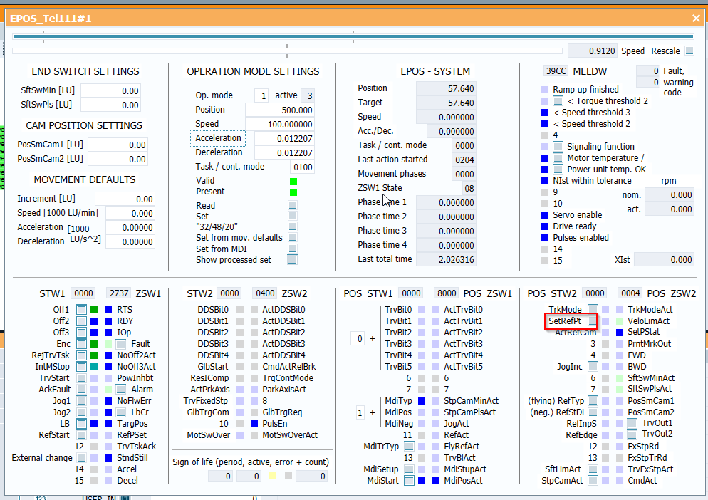
Sure you can use the RefStart Signals and change the homing direction, please reference the manual to get more information.

RefStart Signals is on now!
Finally we only need to turn on the TrvStart bit to execute the task!
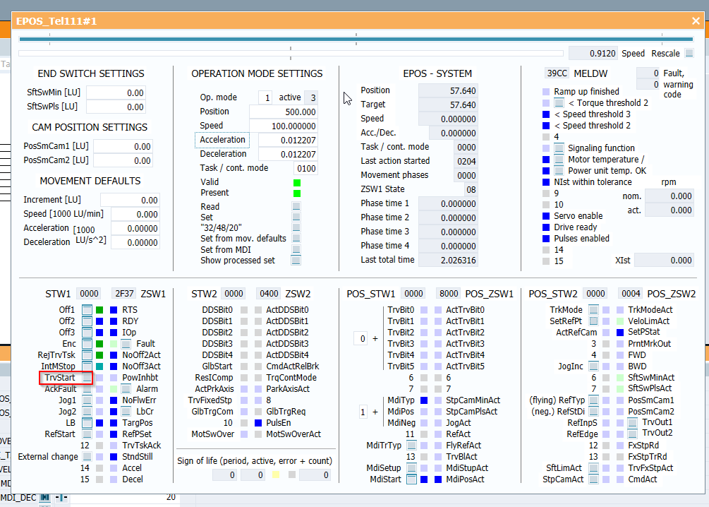
Just like below, the drive will travel to the target position that you set.

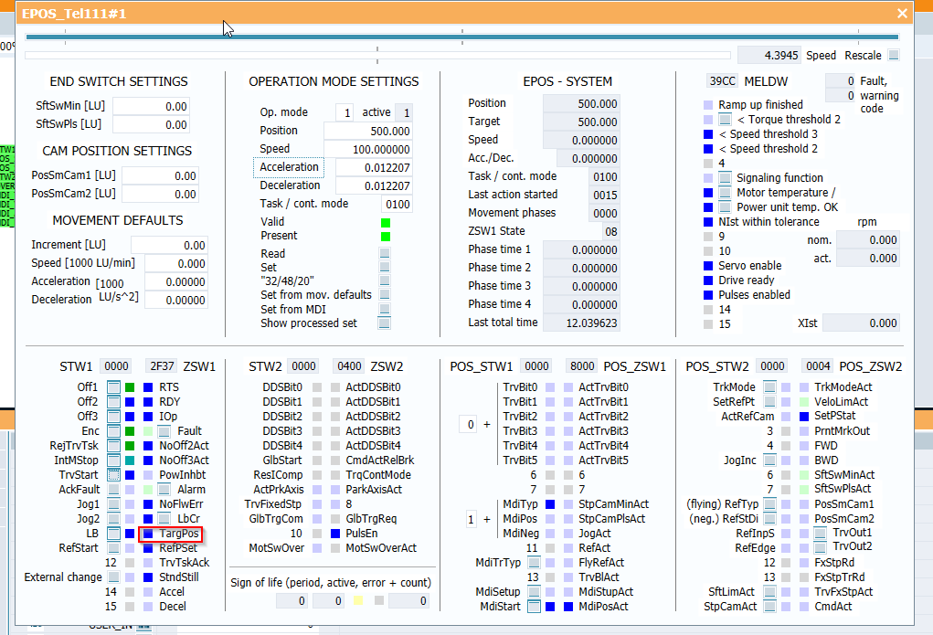
And while the drive has reached the target position, The TargPos of ZSW1 is changed to true.
Relative Positioning From Panel
Then we can test the relative positioning now.
The operation is very similar to Absolute positioning, but just input a value “0” of MidTyp in POS_STW1.
Change the MDI_TARPOS to 50.
It means that the drive will Travel +50 of the current position.
As the gif below, the Position is changed from 500 to 550 after a relative positioning task is done.
Project
SIMIT SIde
Let’s create the simit side first.
Mapping
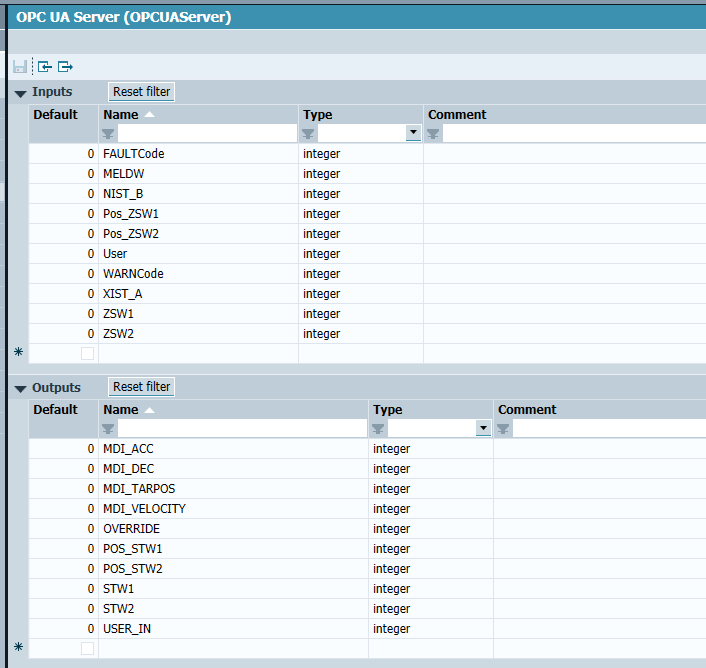
Create an OPC UA Coupling first.

Define the Input/Output Signals.
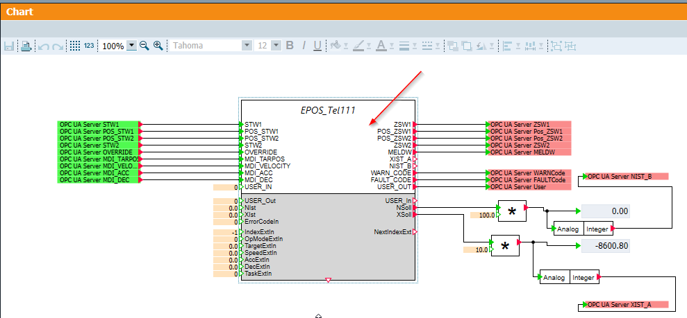
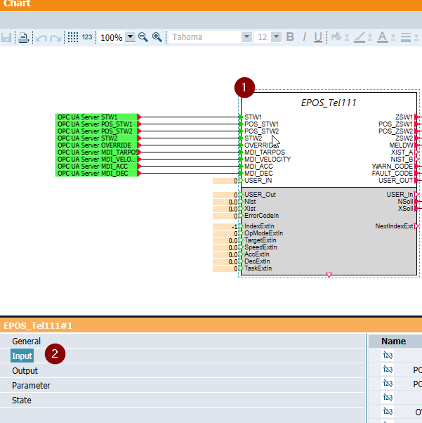
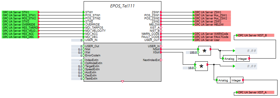
Chart
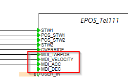
Finally we can assign these signals to the INPUT/OUTPUT of simulation block EPOS_Tel111.
TwinCAT Side
Now we can implement the TwinCAT side. This function block is referenced from the Siemens EPOS Library – SINA_POS function Block.
DUT
DUT_Telg111_ePos_HMI_P
Define the servo operation devices in hmi.
| TYPE DUT_Telg111_ePos_HMI_PB : STRUCT //PB bOFF1 :BOOL; bReset :BOOL; bJogFw :BOOL; bJogbw :BOOL; bHome :BOOL; bMoveAbs :BOOL; bMoveRel :BOOL; //Pars d32CmdVel :DINT:=100; d32CmdAcc :DINT:=10; d32CmdDec :DINT:=10; d32RelPos :DINT:=10; //Station arrStations :ARRAY[0..9]OF DINT; d16CmdStations :INT; // bTableInput :BOOL:=True; END_STRUCT END_TYPE |
DUT_Telg111_ePos_HMI_PL
Define the servo Status devices in hmi.
| TYPE DUT_Telg111_ePos_HMI_PL : STRUCT bReady :BOOL; bBusy :BOOL; bError :BOOL; bWarning :BOOL; bFwing :BOOL; bBwing :BOOL; bHomed :BOOL; bReached :BOOL; bStopped :BOOL; d32ActualSpeed :DINT; d32ActualPos :DINT; d16WarningCode :DINT; d16ErrorCode :DINT; d16StatusWord :DINT; d16ActualStation :int; END_STRUCT END_TYPE |
DUT_Telg111_ePos_HMI
Group the operation and status into one DUT.
| TYPE DUT_Telg111_ePos_HMI : STRUCT PB:DUT_Telg111_ePos_HMI_PB; PL:DUT_Telg111_ePos_HMI_PL; END_STRUCT END_TYPE |
DUT_Telegram111_ePos_Pos_STW1
The DUT of STW1.
| TYPE DUT_Telegram111_ePos_Pos_STW1 : STRUCT bTrvBit0 :BIT; bTrvBit1 :BIT; bTrvBit2 :BIT; bTrvBit3 :BIT; bTrvBit4 :BIT; bTrvBit5 :BIT; b6,b7 :BIT; bMdiTyp :BIT; //0=Relative,1=absolute bMdiPos :BIT; bMdiNeg :BIT; b11 :BIT; bMdiTrTyp :BIT; b13 :BIT; bMdiSetup :BIT; //0=Position,1=Setup bMdiStart :BIT; //Operating mode MDI / direct setpoint specification END_STRUCT END_TYPE |
DUT_Telegram111_ePos_Pos_STW2
The DUT of STW2.
| TYPE DUT_Telegram111_ePos_Pos_STW2 : STRUCT bTrkMode :BIT; bSetRefPt :BIT; bActRefCam :BIT; b3,b4 :BIT; bJogInc :BIT; b6,b7 :BIT; bRefTyp :BIT; bRefStDi :BIT; bRefInpS :BIT; bRefEdge :BIT; b12,b13 :BIT; bSftLimAct :BIT; bStpCamAct :BIT; END_STRUCT END_TYPE |
DUT_Telegram111_ePos_STW1
The DUT of POS_STW1.
| TYPE DUT_Telegram111_ePos_STW1 : STRUCT bOff1 :BIT; bOff2 :BIT; bOff3 :BIT; bEnc :BIT; //Ivnerter Enable bRejTrvTsk :BIT; bIntMStop :BIT; bTrvStart :BIT; //Activate traversing task bAckFault :BIT; bJog1 :BIT; bJog2 :BIT; bLB :BIT; bRefStart :BIT; b12,b13,b14,b15 :BIT; END_STRUCT END_TYPE |
DUT_Telegram111_ePos_STW2
The DUT of POS_STW2.
| TYPE DUT_Telegram111_ePos_STW2 : STRUCT bDDSBit0 :BIT; bDDSBit1 :BIT; bDDSBit2 :BIT; bDDSBit3 :BIT; bDDSBit4 :BIT; bGlbStart :BIT; bResIComp :BIT; bActPrkAxis :BIT; bTrvFixedStp :BIT; bGlbTrgCom :BIT; b10 :BIT; bMotSwOver :BIT; bMsZykBit0 :BIT; bMsZykBit1 :BIT; bMsZykBit2 :BIT; bMsZykBit3 :BIT; END_STRUCT END_TYPE |
u_Telegram111_ePos_STW1
Using union data type to set the DUT and raw data is the same memory offset.
Because SIMIT can not support user data types.
| TYPE u_Telegram111_ePos_STW1 : UNION STW :DUT_Telegram111_ePos_STW1; raw :LINT; END_UNION END_TYPE |
u_Telegram111_ePos_STW2
Using union data type to set the DUT and raw data is the same memory offset.
Because SIMIT can not support user data types.
| TYPE u_Telegram111_ePos_STW2 : UNION STW :DUT_Telegram111_ePos_STW2; raw :LINT; END_UNION END_TYPE |
DUT_Telegram111_ePos_STW
Finally , Group all the STW into one DUT, Done!
| TYPE DUT_Telegram111_ePos_STW : STRUCT STW1 :u_Telegram111_ePos_STW1; Pos_STW1 :u_Telegram111_ePos_Pos_STW1; Pos_STW2 :u_Telegram111_ePos_Pos_STW2; STW2 :u_Telegram111_ePos_STW2; OVERRIDE :LINT; MDI_TAGPOS :LINT; MDI_VELOCITY :LINT; MDI_ACC :LINT; MDI_DEC :LINT; User :LINT; END_STRUCT END_TYPE |
DUT_Telegram111_ePos_Pos_ZSW1
The DUT of ZSW1.
| TYPE DUT_Telegram111_ePos_Pos_ZSW1 : STRUCT bActTrvBit0 :BIT; bActTrvBit1 :BIT; bActTrvBit2 :BIT; bActTrvBit3 :BIT; bActTrvBit4 :BIT; bActTrvBit5 :BIT; b6,b7 :BIT; bStpCamMinAct :BIT; bStpCamPlsAct :BIT; bJogAct :BIT; bRefAct :BIT; bFlyRefAct :BIT; bTrvBlAct :BIT; bMdiStupAct :BIT; bMdiPosAct :BIT; END_STRUCT END_TYPE |
DUT_Telegram111_ePos_Pos_ZSW2
The DUT of ZSW2.
| TYPE DUT_Telegram111_ePos_Pos_ZSW2 : STRUCT bTrkModeAct :BIT; bVeloLimAct :BIT; bSetPStat :BIT; bPrntMrkOut :BIT; bFWD :BIT; bBWD :BIT; bSftSwMinAct :BIT; bSftSwPlsAct :BIT; bPosSmCam1 :BIT; bPosSmCam2 :BIT; bTrvOut1 :BIT; bTrvOut2 :BIT; bFxStpRd :BIT; bFxStpTrRd :BIT; bTrvFxStpAct :BIT; bCmdAct :BIT; END_STRUCT END_TYPE |
DUT_Telegram111_ePos_ZSW1
The DUT of POS_ZSW1.
| TYPE DUT_Telegram111_ePos_ZSW1 : STRUCT bRTS :BIT; bRDY :BIT; bIOp :BIT; bFault :BIT; bNoOff2Act :BIT; bNoOff3Act :BIT; bPowInhbt :BIT; bAlarm :BIT; bNoFlwErr :BIT; bLbCr :BIT; bTargPos :BIT; bRefPSet :BIT; bTrvTskAck :BIT; bStndStill :BIT; bAccel :BIT; bDecel :BIT; END_STRUCT END_TYPE |
DUT_Telegram111_ePos_ZSW2
The DUT of ZSW2.
| TYPE DUT_Telegram111_ePos_ZSW2 : STRUCT bActDDSBit0 :BIT; bActDDSBit1 :BIT; bActDDSBit2 :BIT; bActDDSBit3 :BIT; bActDDSBit4 :BIT; bCmdActRelBrk :BIT; bTrqContMode :BIT; bParkAxisAct :BIT; b8 :BIT; bGlbTrgReq :BIT; bPulsEn :BIT; bMotSwOverAct :BIT; bSlvZykBit0 :BIT; bSlvZykBit1 :BIT; bSlvZykBit2 :BIT; bSlvZykBit3 :BIT; END_STRUCT END_TYPE |
u_Telegram111_ePos_Pos_ZSW1
Using union data type to set the DUT and raw data is the same memory offset.
Because SIMIT can not support user data types.
| TYPE u_Telegram111_ePos_Pos_ZSW1 : UNION ZSW :DUT_Telegram111_ePos_Pos_ZSW1; raw :LINT; END_UNION END_TYPE |
u_Telegram111_ePos_Pos_ZSW2
Using union data type to set the DUT and raw data is the same memory offset.
Because SIMIT can not support user data types.
| TYPE u_Telegram111_ePos_Pos_ZSW2 : UNION ZSW :DUT_Telegram111_ePos_Pos_ZSW2; raw :LINT; END_UNION END_TYPE |
u_Telegram111_ePos_ZSW1
Using union data type to set the DUT and raw data is the same memory offset.
Because SIMIT can not support user data types.
| TYPE u_Telegram111_ePos_ZSW1 : UNION ZSW :DUT_Telegram111_ePos_ZSW1; raw :LINT; END_UNION END_TYPE |
u_Telegram111_ePos_ZSW2
Using union data type to set the DUT and raw data is the same memory offset.
Because SIMIT can not support user data types.
| TYPE u_Telegram111_ePos_ZSW2 : UNION ZSW :DUT_Telegram111_ePos_ZSW2; raw :LINT; END_UNION END_TYPE |
DUT_Telegram111_ePos_ZSW
Finally , Group all the ZSW into one DUT, Done!
| TYPE DUT_Telegram111_ePos_ZSW : STRUCT ZSW1 :u_Telegram111_ePos_ZSW1; POS_ZSW1 :u_Telegram111_ePos_Pos_ZSW1; POS_ZSW2 :u_Telegram111_ePos_Pos_ZSW2; ZSW2 :u_Telegram111_ePos_ZSW2; MELDW :LINT; XIST_A :LINT; NIST_B :LINT; FAULTCode :LINT; WARNCode :LINT; User :LINT; END_STRUCT END_TYPE |
DUT_Telegram111_ePos
This is a DUT for me to define the process IO of STW and ZSW into a variable and this DUT is used inside the function block.
| TYPE DUT_Telegram111_ePos : STRUCT STW AT %Q* :DUT_Telegram111_ePos_STW; ZSW AT %I* :DUT_Telegram111_ePos_ZSW; END_STRUCT END_TYPE |
FB_Telgram111_Basic
This Function block implements Telegram111 with Mdi Mode – Servo on, home, jog operation and Absolute/Relative Positioning.Because It is a draft version ,interlocking is not enough to protect all the operations.It may be better to extend this Block and overwrite some methods.
VAR
| FUNCTION_BLOCK FB_Telgram111_Basic IMPLEMENTS ITF_Teleg111 VAR_INPUT END_VAR VAR_OUTPUT END_VAR VAR IOs :DUT_Telegram111_ePos; _bError :BOOL; _bWarning :BOOL; END_VAR |
PROPERTY Busy : BOOL
GET
True is returned while the servo command is executing.
| Busy:=NOT Fwing AND NOT Bwing AND NOT IOs.ZSW.POS_ZSW2.ZSW.bCmdAct ; |
PROPERTY Bwing : BOOL
GET
True is returned while the servo is backwarding.
| Bwing:=IOs.ZSW.POS_ZSW2.ZSW.bBWD; |
PROPERTY DriveErroCode : DINT
GET
Return the Error code of the servo.
| DriveErroCode:=LINT_TO_DINT(IOs.ZSW.WARNCode); |
PROPERTY DriveStatusCode : DINT
GET
Return the status code of the servo.
| DriveStatusCode:=LINT_to_DINT(IOs.ZSW.MELDW); |
PROPERTY DriveWarningCode : DINT
GET
Return the warning code of the servo.
| DriveWarningCode:=LINT_TO_DINT(IOs.ZSW.WARNCode); |
PROPERTY Error : BOOL
True is returned while the servo is in error.
GET
| Error:=IOs.ZSW.ZSW1.ZSW.bFault; |
PROPERTY Fwing : BOOL
True is returned while the servo is forwarding.
GET
| Fwing:=IOs.ZSW.POS_ZSW2.ZSW.bFWD; |
PROPERTY Homed : BOOL
True is returned while the referenced point is set.
GET
| Homed:=IOs.ZSW.ZSW1.ZSW.bRefPSet; |
PROPERTY ReachPosition : BOOL
True is returned while the positioning task is done.
GET
| ReachPosition:=IOs.ZSW.ZSW1.ZSW.bTargPos; |
PROPERTY Ready : BOOL
True is returned while the servo is ready.
GET
| Ready:=IOs.ZSW.ZSW1.ZSW.bIOp; |
PROPERTY Stopped : BOOL
True is returned when the servo is stopped.
GET
| Stopped:=NOT Fwing AND NOT Bwing; |
PROPERTY Warning : BOOL
True is returned while the servo is in warning.
GET
| Warning:=IOs.ZSW.ZSW1.ZSW.bAlarm; |
PROPERTY ActualPos : DINT
return the actual position.
GET
| ActualPos:=LINT_TO_DINT(IOs.ZSW.XIST_A); |
PROPERTY ActualSpeed : DINT
return the actual speed.
GET
| ActualSpeed:=LINT_TO_DINT(IOs.ZSW.NIST_B); |
METHOD Home : BOOL
A method to set the servo reference point.
| VAR_INPUT in : BOOL; END_VAR VAR_INST R_TRIG:R_TRIG; TON:TON; END_VAR R_TRIG( CLK:=in ); IF R_TRIG.Q AND Stopped AND NOT Error THEN IOs.STW.Pos_STW2.STW.bSetRefPt:=TRUE; END_IF TON(IN:=IOs.STW.Pos_STW2.STW.bSetRefPt ,PT:=T#1S ); IF TON.Q THEN IOs.STW.Pos_STW2.STW.bSetRefPt:=False; END_IF |
METHOD JogBW : BOOL
A method to operate the servo in a Backward direction.
| VAR_INPUT in:BOOL; END_VAR IOs.STW.STW1.STW.bJog2:=in AND NOT Error; JogBW:=IOs.STW.STW1.STW.bJog2; |
METHOD JogFW : BOOL
A method to operate the servo in a Forward direction.
| VAR_INPUT in:BOOL; END_VAR IOs.STW.STW1.STW.bJog1:=in AND NOT Error; JogFW:=IOs.STW.STW1.STW.bJog1; |
METHOD moveAbs : BOOL
A method to operate the servo in Absolute positioning mode.
| VAR_INPUT in : BOOL; pos:DINT; vel:DINT; Acc:DINT; dec:DINT; END_VAR VAR_INST StartCmd :R_TRIG; CmdDelay :TON; CmdOff :TON; END_VAR . CmdDelay( IN:=CmdDelay.Q AND NOT Busy AND Homed ,PT:=T#0.2S ); StartCmd( CLK:=in ); IF StartCmd.Q THEN IOs.STW.Pos_STW1.STW.bMdiTyp:=TRUE; IOs.STW.MDI_TAGPOS:=pos; IOs.STW.MDI_ACC:=Acc; IOs.STW.MDI_DEC:=dec; IOs.STW.MDI_VELOCITY:=vel; IOs.STW.STW1.STW.bTrvStart:=TRUE; END_IF CmdOff( IN:=IOs.STW.STW1.STW.bTrvStart ,PT:=T#1S ); IF CmdOff.Q THEN IOs.STW.STW1.STW.bTrvStart:=FALSE; END_IF moveAbs:=IOs.STW.Pos_STW1.STW.bMdiTyp ; |
METHOD moveRel : BOOL
A method to operate the servo in Relative positioning mode.
| VAR_INPUT in : BOOL; pos : DINT; vel : DINT; Acc : DINT; dec : DINT; END_VAR VAR_INST StartCmd :R_TRIG; CmdDelay :TON; CmdOff :TON; END_VAR CmdDelay( IN:=CmdDelay.Q AND NOT Busy AND Homed ,PT:=T#0.2S ); StartCmd( CLK:=in ); IF StartCmd.Q THEN IOs.STW.Pos_STW1.STW.bMdiTyp:=FALSE; IOs.STW.MDI_TAGPOS:=pos; IOs.STW.MDI_ACC:=Acc; IOs.STW.MDI_DEC:=dec; IOs.STW.MDI_VELOCITY:=vel; IOs.STW.STW1.STW.bTrvStart:=TRUE; END_IF CmdOff( IN:=IOs.STW.STW1.STW.bTrvStart ,PT:=T#1S ); IF CmdOff.Q THEN IOs.STW.STW1.STW.bTrvStart:=FALSE; END_IF moveRel:=NOT IOs.STW.Pos_STW1.STW.bMdiTyp ; |
METHOD Reset : BOOL
A method to reset the Servo.
| VAR_INPUT in:BOOL; END_VAR IOs.STW.STW1.STW.bAckFault:=in; |
METHOD ServoON : BOOL
A method to Turn on the Servo on the OFF1 bit.
| VAR_INPUT in : BOOL; END_VAR VAR_INST TON:TON; END_VAR TON(IN:=in ,PT:=T#0.2S ); IOs.STW.STW1.STW.bOff1:=TON.Q; |
METHOD SetDefaultConfiguration : BOOL
A method to write the basic configuration and please modify the status base on application.
| IOs.STW.STW1.STW.bOff2 :=TRUE; IOs.STW.STW1.STW.bOff3 :=TRUE; IOs.STW.STW1.STW.bEnc :=TRUE; IOs.STW.STW1.STW.bIntMStop :=TRUE; IOs.STW.STW1.STW.bRejTrvTsk :=TRUE; IOs.STW.STW1.STW.bLB :=TRUE; IOs.STW.Pos_STW1.STW.bMdiStart :=TRUE; |
POU-MAIN
This Time I will not integrate the HMI devices into my function block, because most of the libraries provided from Beckhoff/Siemens/Codesys are only implemented in the basic level,
The user needs to implement the interface linking to other devices like HMI,interlock..etc.
This sample code will show you how to check the opc ua connection>call the function block>servo on>reset>home>jog>error detection>wait the positioning task>refresh the hmi data.
| PROGRAM MAIN VAR bEnable:BOOL; OpcUaDeviceStatus AT %I*:OpcUaDeviceStatus; OpcUaDeviceControl AT %Q*:OpcUaDeviceControl; Servo1 :FB_Telgram111_Basic; HMIs:DUT_Telg111_ePos_HMI; bCmdsVaild:BOOL; BackupCmd:INT; d32Cmdpos:DINT; bIL:BOOL; R_TRIG,PosReached,AbsMoving:R_TRIG; END_VAR IF OpcUaDeviceStatus.Connected THEN OpcUaDeviceControl.Write_Enable:=TRUE; bEnable:=True; ELSE OpcUaDeviceControl.Write_Enable:=FALSE; bEnable:=FALSE; END_IF Servo1(); Servo1.SetDefaultConfiguration(); Servo1.ServoON(in:=HMIs.PB.bOFF1 AND bEnable); Servo1.Reset(in:=HMIs.PB.bReset); Servo1.Home(in:=HMIs.PB.bHome); R_TRIG( CLK:=Servo1.Homed ); IF R_TRIG.Q THEN HMIs.PB.bHome:=FALSE; END_IF; bIL:= NOT HMIs.PB.bMoveRel AND NOT HMIs.PB.bJogbw AND NOT HMIs.PB.bMoveAbs; IF Servo1.JogFW(in:=HMIs.PB.bJogFw AND bIL) THEN HMIs.PL.d16ActualStation:=0; END_IF bIL:= NOT HMIs.PB.bMoveRel AND NOT HMIs.PB.bJogfw AND NOT HMIs.PB.bMoveAbs; IF Servo1.JogBW(in:=HMIs.PB.bJogbw AND bIL) THEN HMIs.PL.d16ActualStation:=0; END_IF bIL:= NOT HMIs.PB.bMoveRel AND NOT HMIs.PB.bJogbw AND NOT HMIs.PB.bJogFw; bCmdsVaild:=HMIs.PB.d16CmdStations <>0 AND BackupCmd <> HMIs.PB.d16CmdStations; AbsMoving(CLK:=HMIs.PB.bMoveAbs AND bCmdsVaild AND bIL); IF AbsMoving.Q THEN d32Cmdpos:=HMIs.PB.arrStations[HMIs.PB.d16CmdStations]; BackupCmd:=HMIs.PB.d16CmdStations; HMIs.PB.d16CmdStations:=0; HMIs.PL.d16ActualStation:=0; END_IF Servo1.moveAbs( in:=HMIs.PB.bMoveAbs AND bCmdsVaild ,pos:=d32Cmdpos ,vel:=HMIs.PB.d32CmdVel ,Acc:=HMIs.PB.d32CmdAcc ,dec:=HMIs.PB.d32CmdDec ) ; bIL:= NOT HMIs.PB.bMoveAbs AND NOT HMIs.PB.bJogbw AND NOT HMIs.PB.bJogFw; IF Servo1.moveRel( in:=HMIs.PB.bMoveRel AND bIL ,pos:=HMIs.PB.d32RelPos ,vel:=HMIs.PB.d32CmdVel ,Acc:=HMIs.PB.d32CmdAcc ,dec:=HMIs.PB.d32CmdDec) THEN HMIs.PL.d16ActualStation:=0; END_IF; PosReached(CLK:=Servo1.ReachPosition); IF PosReached.Q THEN HMIs.PL.d16ActualStation:=BackupCmd; HMIs.PB.d16CmdStations:=0; BackupCmd:=0; END_IF //Status HMIs.PL.bBusy:=Servo1.Busy; HMIs.PL.bBwing:=Servo1.Bwing; HMIs.PL.bFwing:=Servo1.Fwing; HMIs.PL.bError:=Servo1.Error; HMIs.PL.bHomed:=Servo1.Homed; HMIs.PL.bReached:=Servo1.ReachPosition; HMIs.PL.bReady:=Servo1.Ready; HMIs.PL.bStopped:=Servo1.Stopped; HMIs.PL.bWarning:=Servo1.Warning; HMIs.PL.d32ActualPos:=Servo1.ActualPos/10; HMIs.PL.d32ActualSpeed:=Servo1.ActualSpeed/100; HMIs.PL.d16ErrorCode:=Servo1.DriveErroCode; HMIs.PL.d16StatusWord:=Servo1.DriveStatusCode; HMIs.PL.d16WarningCode:=Servo1.DriveWarningCode; HMIs.PB.arrStations[1]:=-100; HMIs.PB.arrStations[2]:=100; HMIs.PB.arrStations[3]:=150; HMIs.PB.arrStations[4]:=300; HMIs.PB.arrStations[5]:=10; HMIs.PB.arrStations[6]:=0; HMIs.PB.arrStations[7]:=-40; HMIs.PB.arrStations[8]:=60; HMIs.PB.arrStations[9]:=90; |
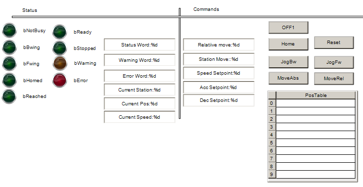
Visualization
Here is the HMI operation screen.
Result
The function block will send the command depending on the hmi.
Jog
Rel
Abs
Source Code
https://github.com/soup01Threes/TwinCAT3/blob/main/TwinCAT%20Project1_Telegram111_WithSIMIT.zip