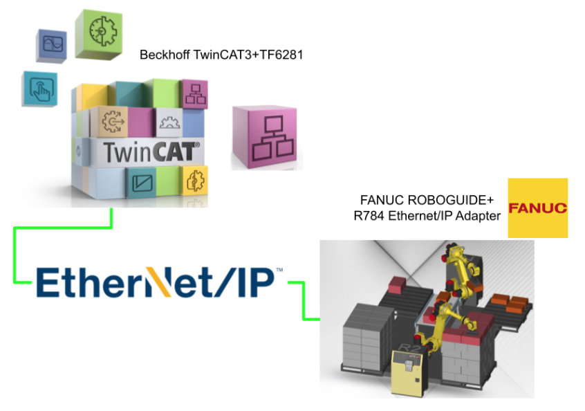
In this article, we will start up an Ethernet/IP Scanner with Beckhoff TwinCAT3 and TF6281 and connect it to Ethernet/IP Adapter with R784 Options on the FANUC ROBOGUIDE side.
The IO data mapping method on the FANUC ROBOGUIDE side is also explained, and the Enable and Reset signals are actually sent from the TwinCAT side.
Step by Step, From Zero To Hero.
Let’s get started!
Implementation
FANUC Side
We start with the FANUC ROBOGUIDE side.
Options
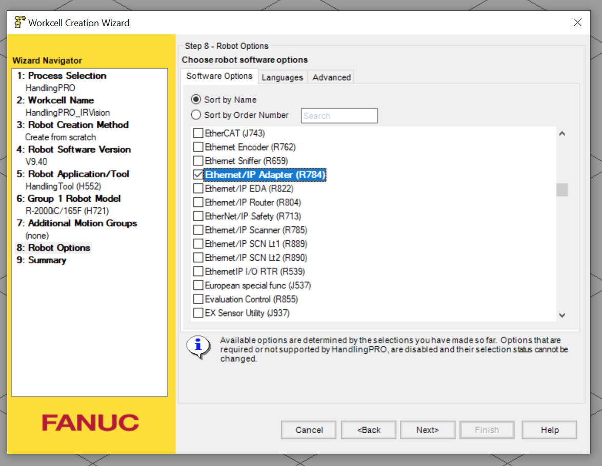
R784 Options are required to use the Ethernet/IP Adapter.
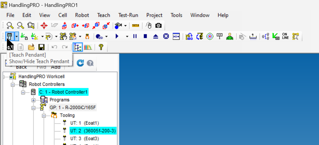
Start Teach Pendant
Start Teach Pedant to change Robot settings.
Host Comm
Initially, open 6 SETUP>SETUP 2>8 HOST Comm for basic Ethernet configuration.
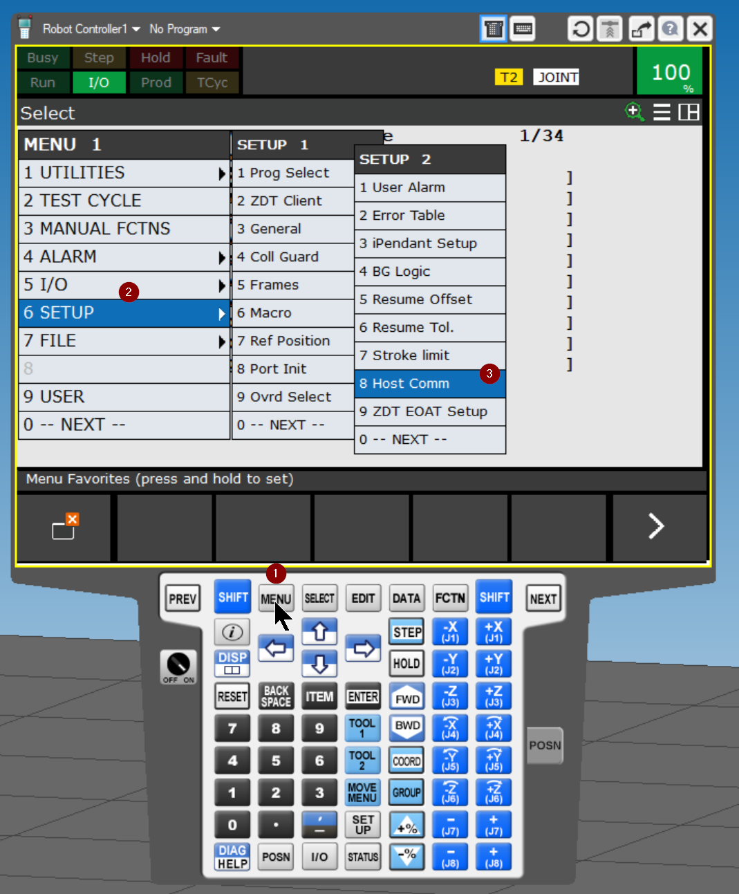
Go to 1 Open TCP/IP.
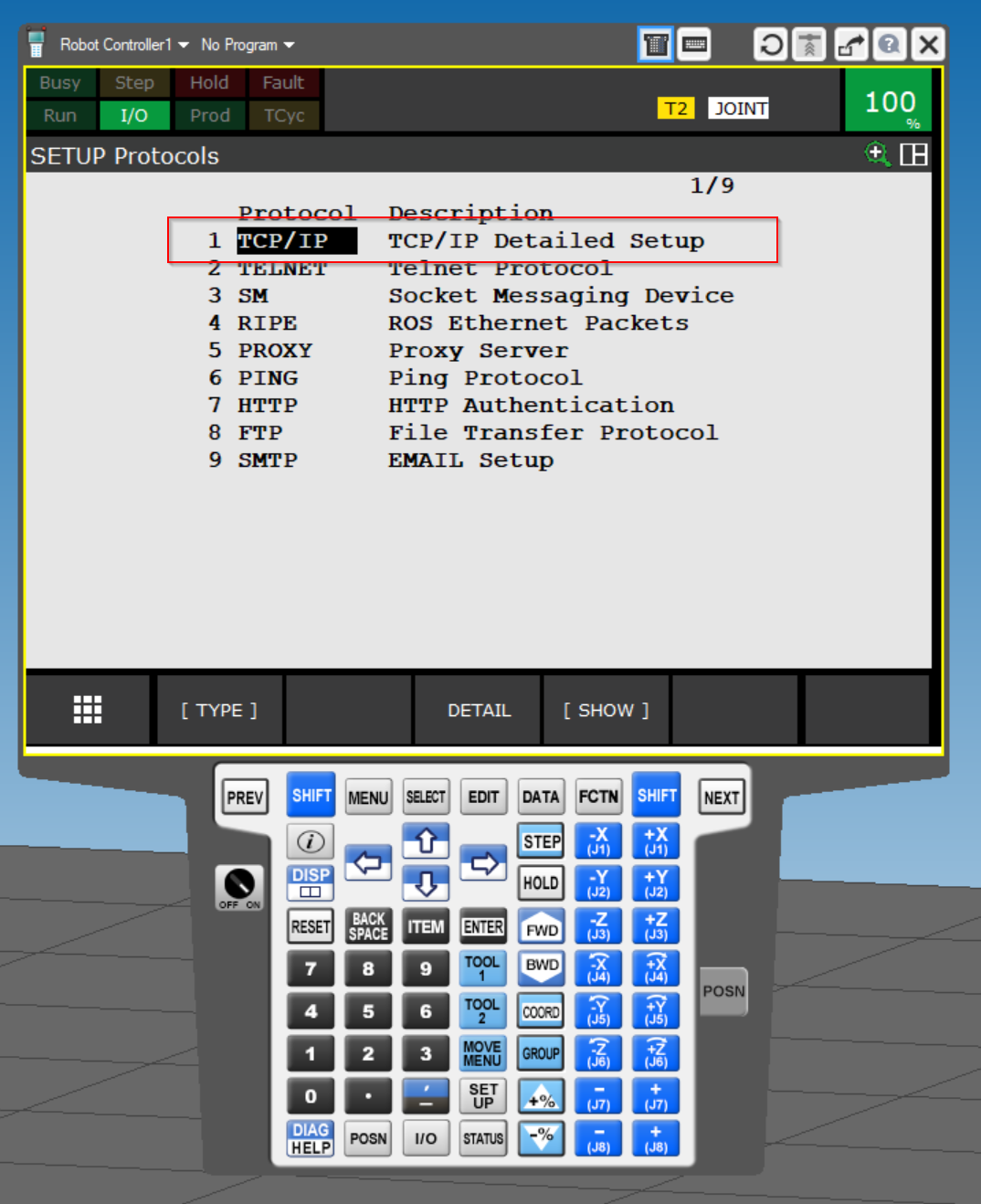
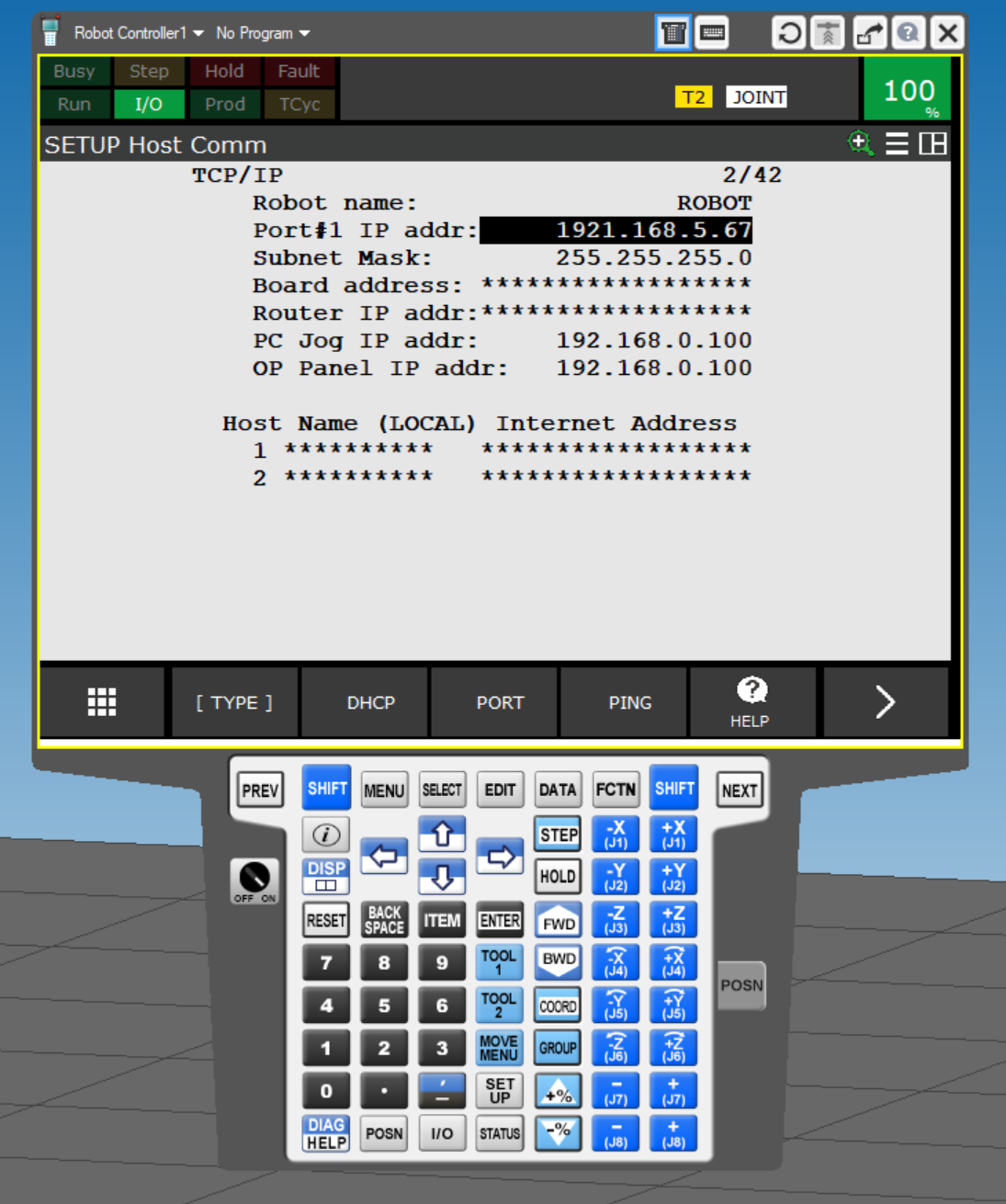
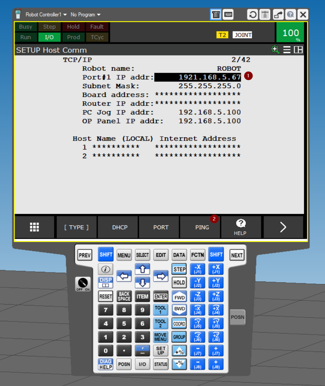
Here you can set ROBOT’s IP address, etc.
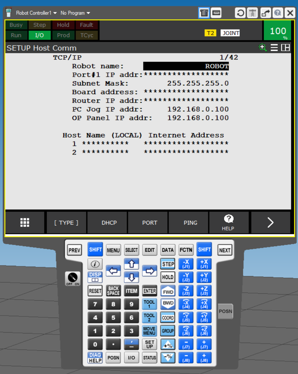
Port #1 IP addr
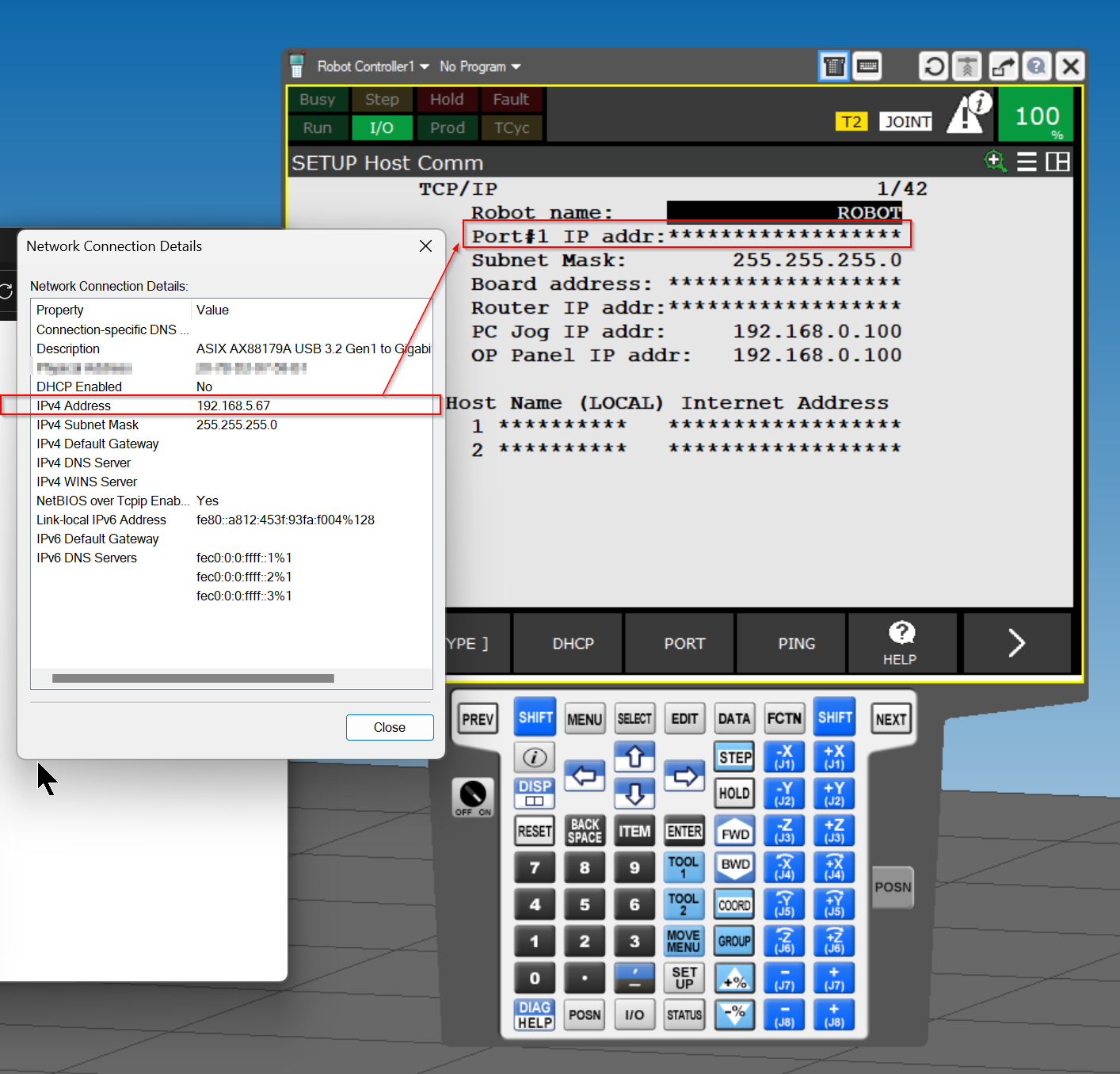
The IP address here should be set to the same as the Network Adapter on the PC.
Done!
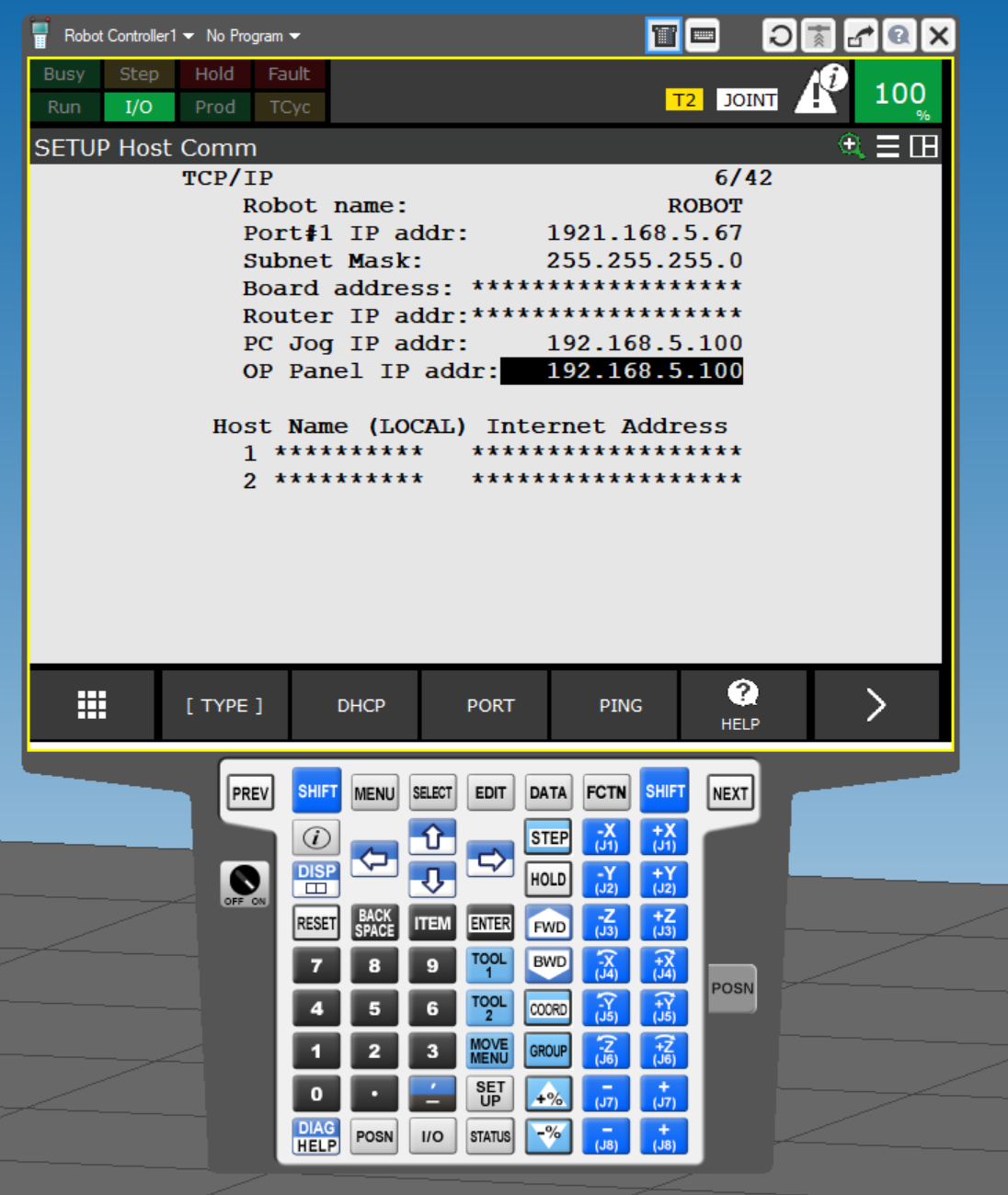
PC Jog/OP Panel IP
Set the Panel IP, etc.
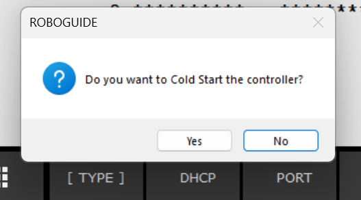
Restart
Restart Robot Controller.
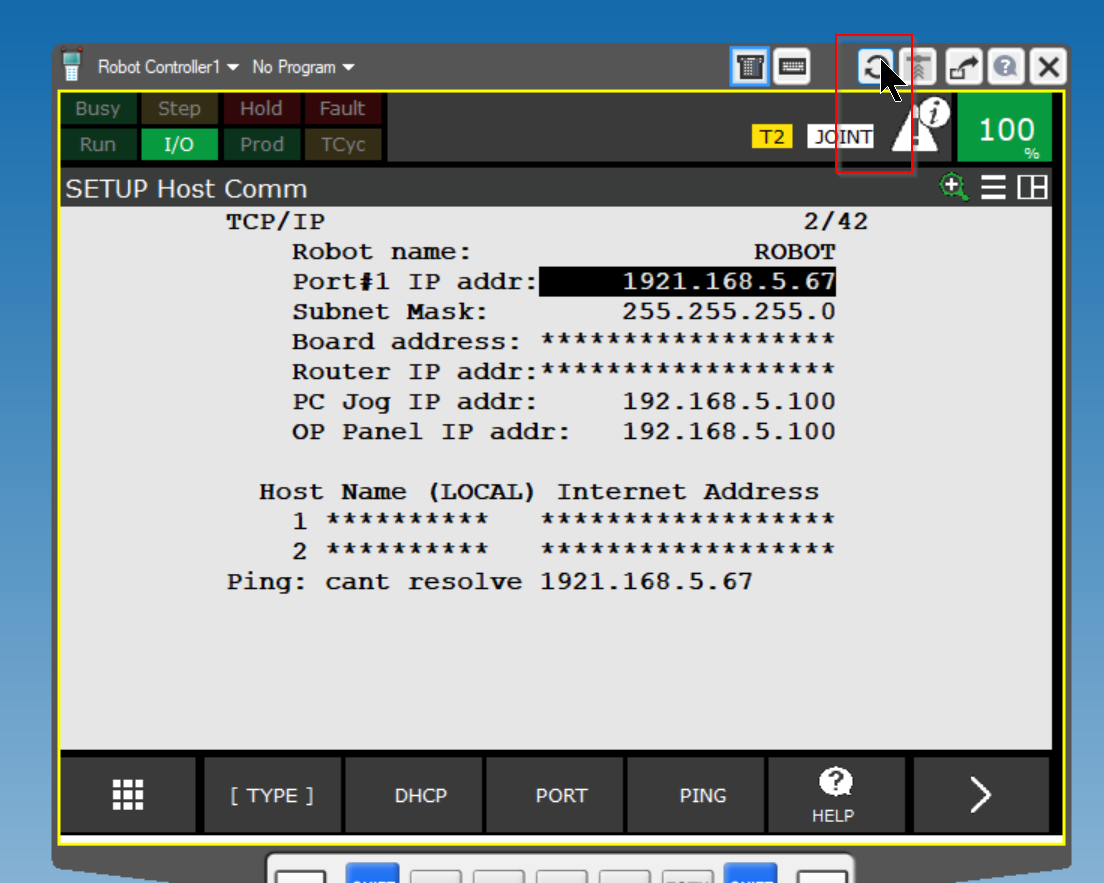
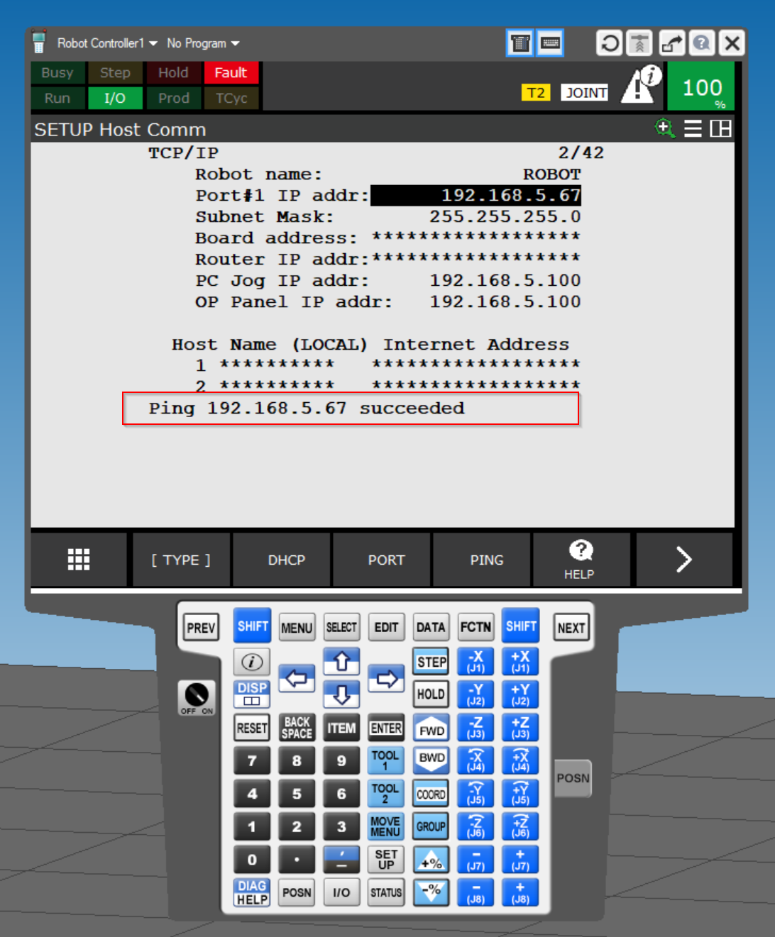
PING
Select Port #1 IP addr and use the PING function to test the connection.
Done!
Ethernet/IP Setting
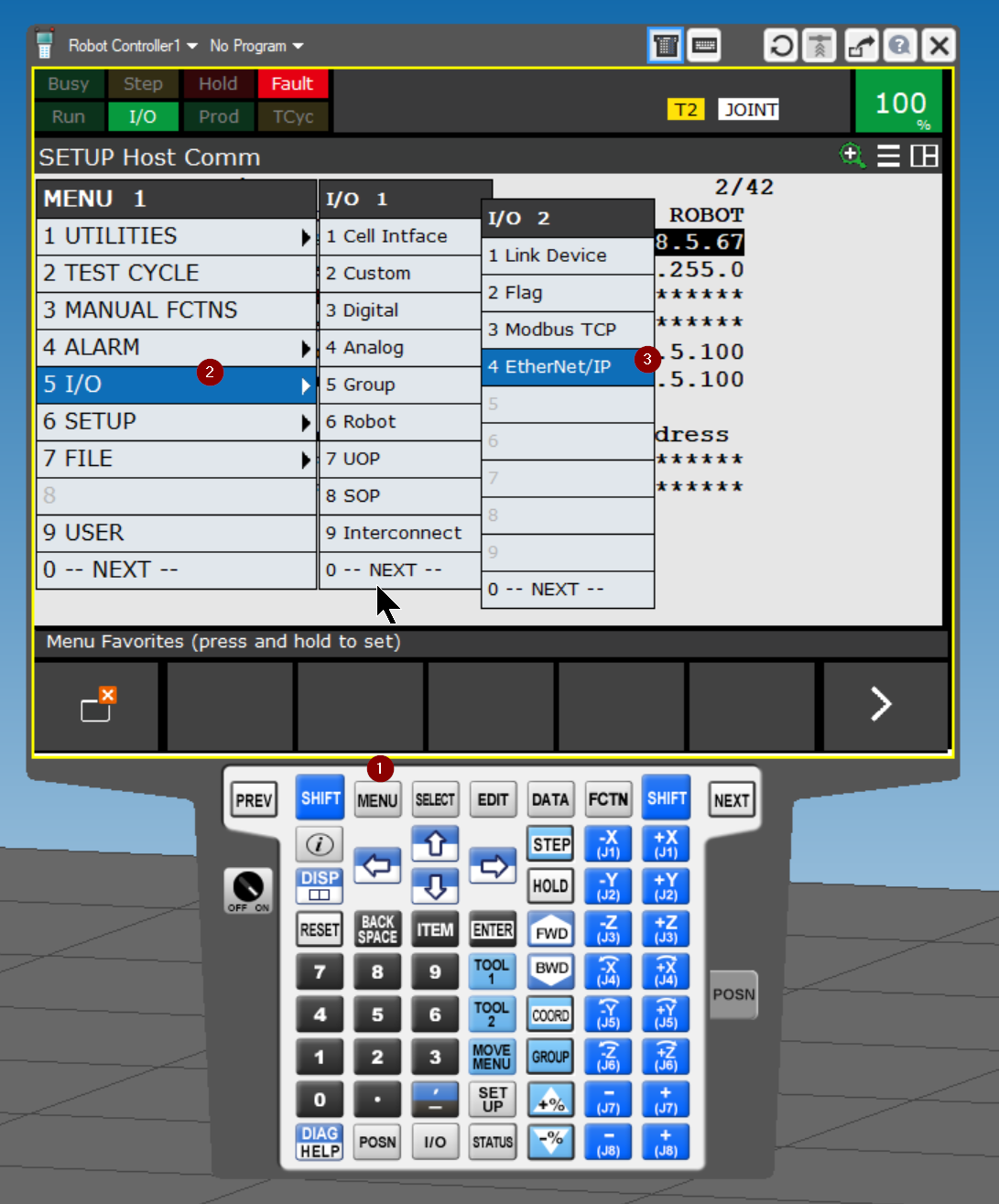
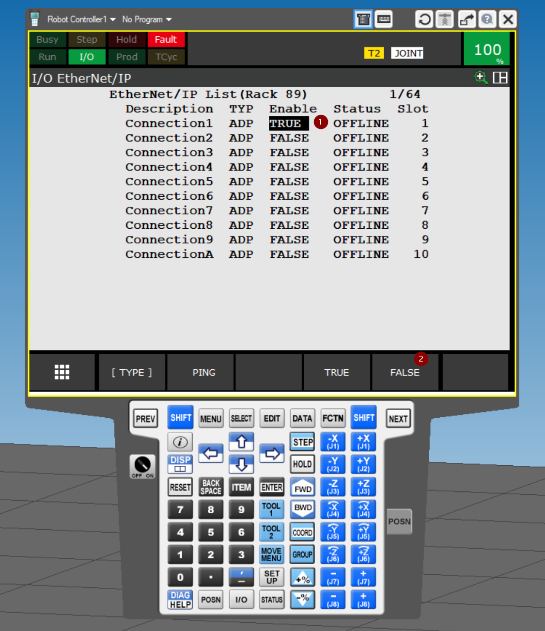
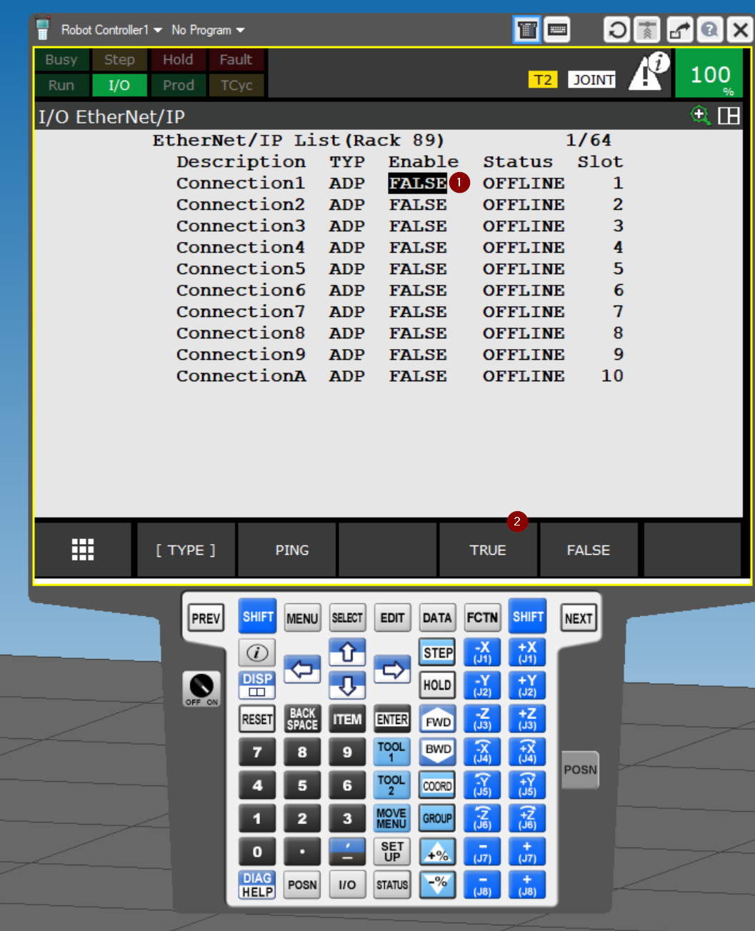
Now open 5 I/O>I/O 2>4 Ethernet/IP to configure Ethernet/IP.
Connection1 will be used in this article.
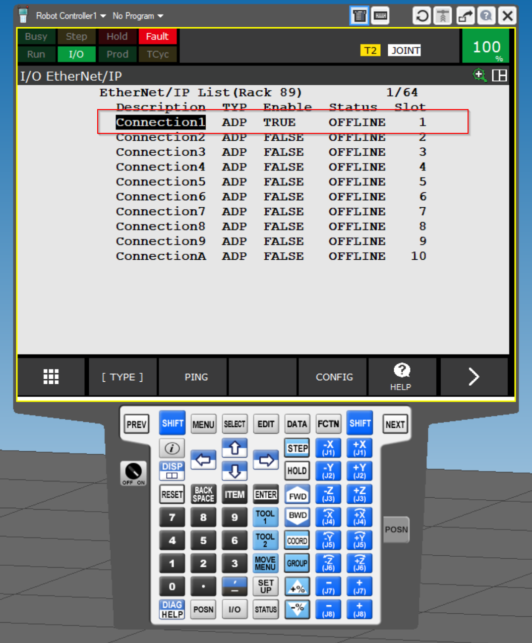
Disable
To change the Adapter function of the FANUC robot, we must first disable Connetion: select the Enable field and click > FALSE.
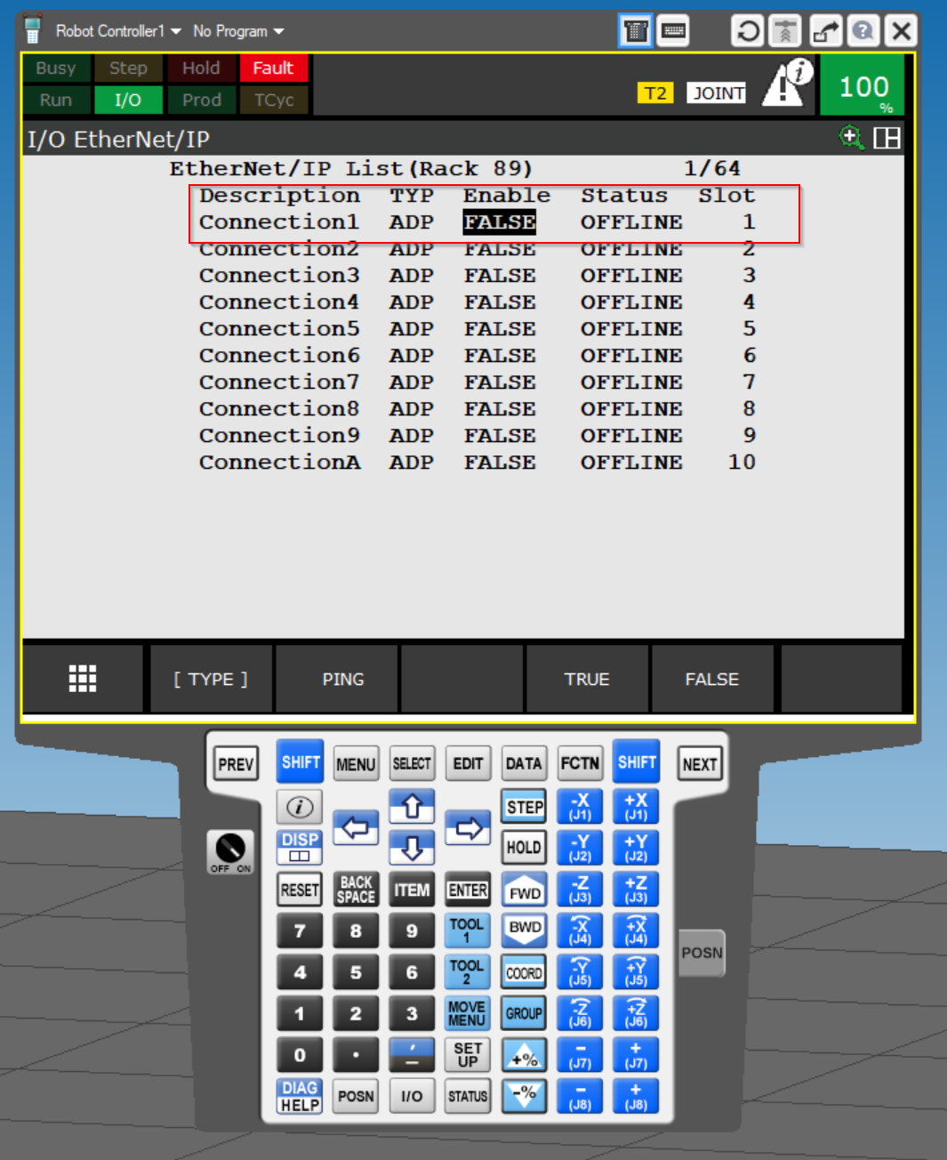
The Enable state of Connection1 is now FALSE.
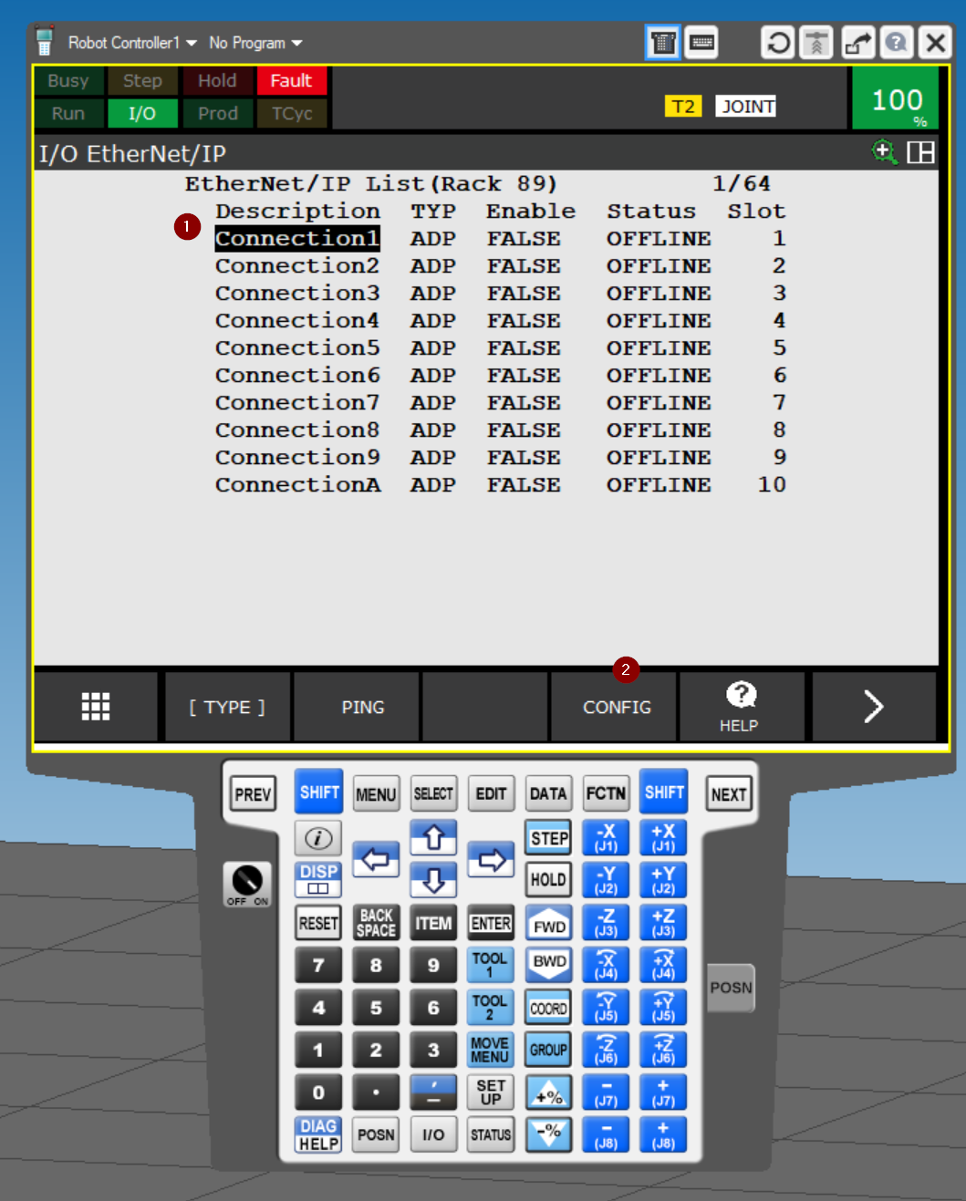
CONFIG
If you want to change the settings for Conenction1, select Connection1 and click >CONFIG.
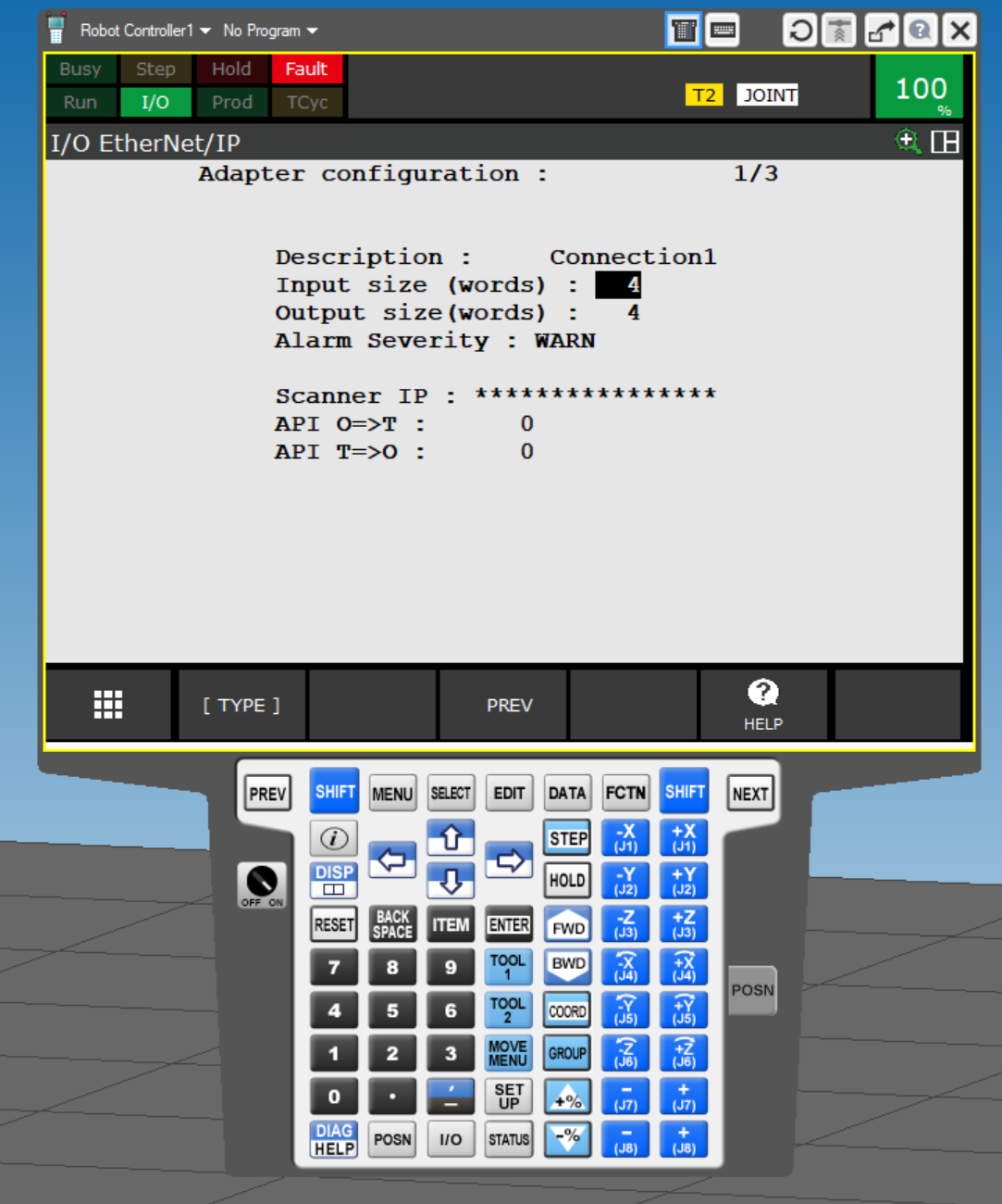
The setting screen for Connection 1 is currently displayed.
Enable
Don’t forget to set Adapter back to Enable at the end.
Variables
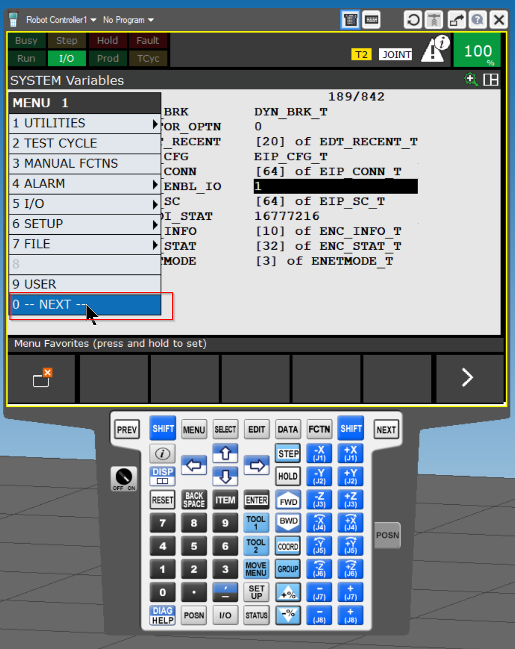
Next, open MENU 1>0–NEXT– to modify the System variable.
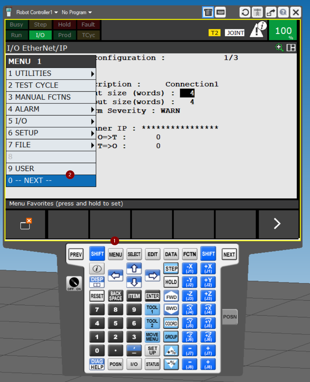
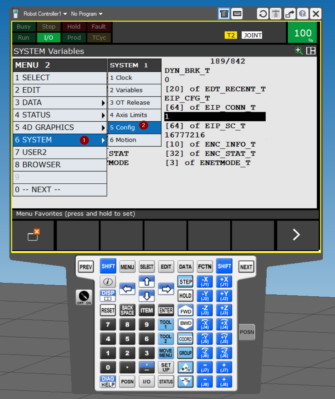
MENU2 appears and opens the 6 SYSTEM> 2 Variables screen.
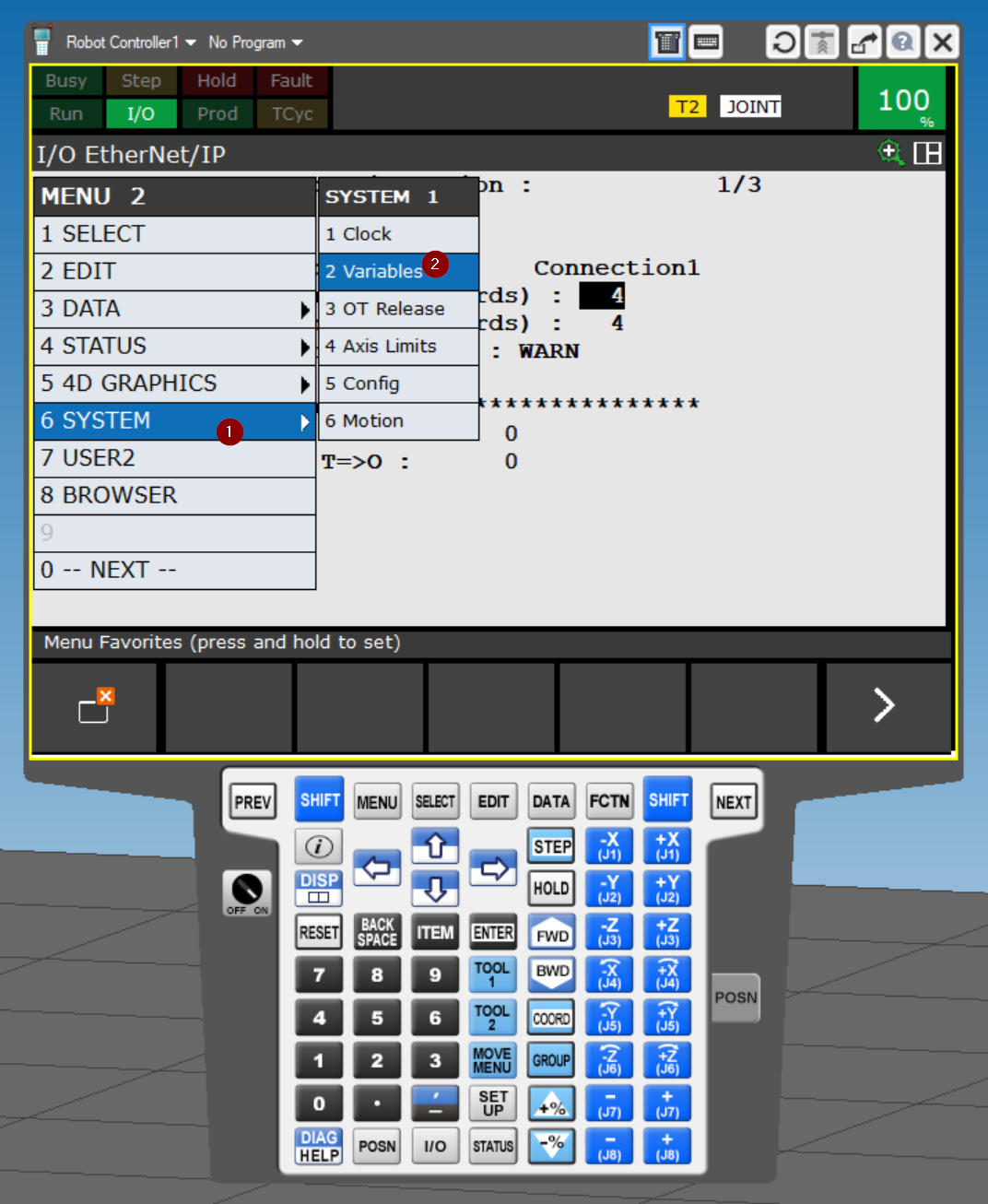
This is the system variable setting screen of FANUC Robot Controller.
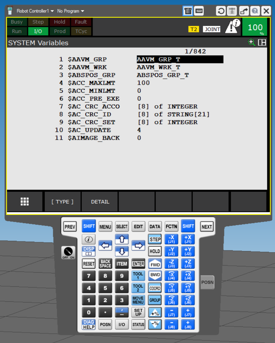
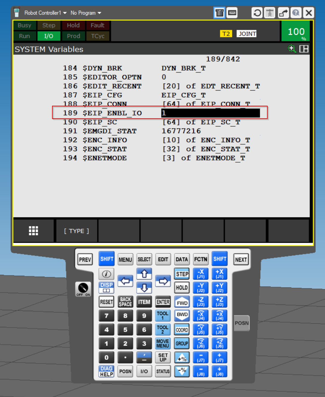
189 There is a variable named $EIP_ENBL_IO.
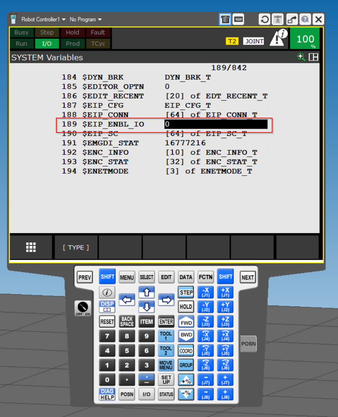
Set $EIP_ENBL_IO to 1.
Config
Now click MENU 1>0–NEXT– to change the robot controller settings.
Go to MENU 2 >6 SYSTEM> 5 Config.
The item 42 Remote/Local Setup is OP panel Key as Default.
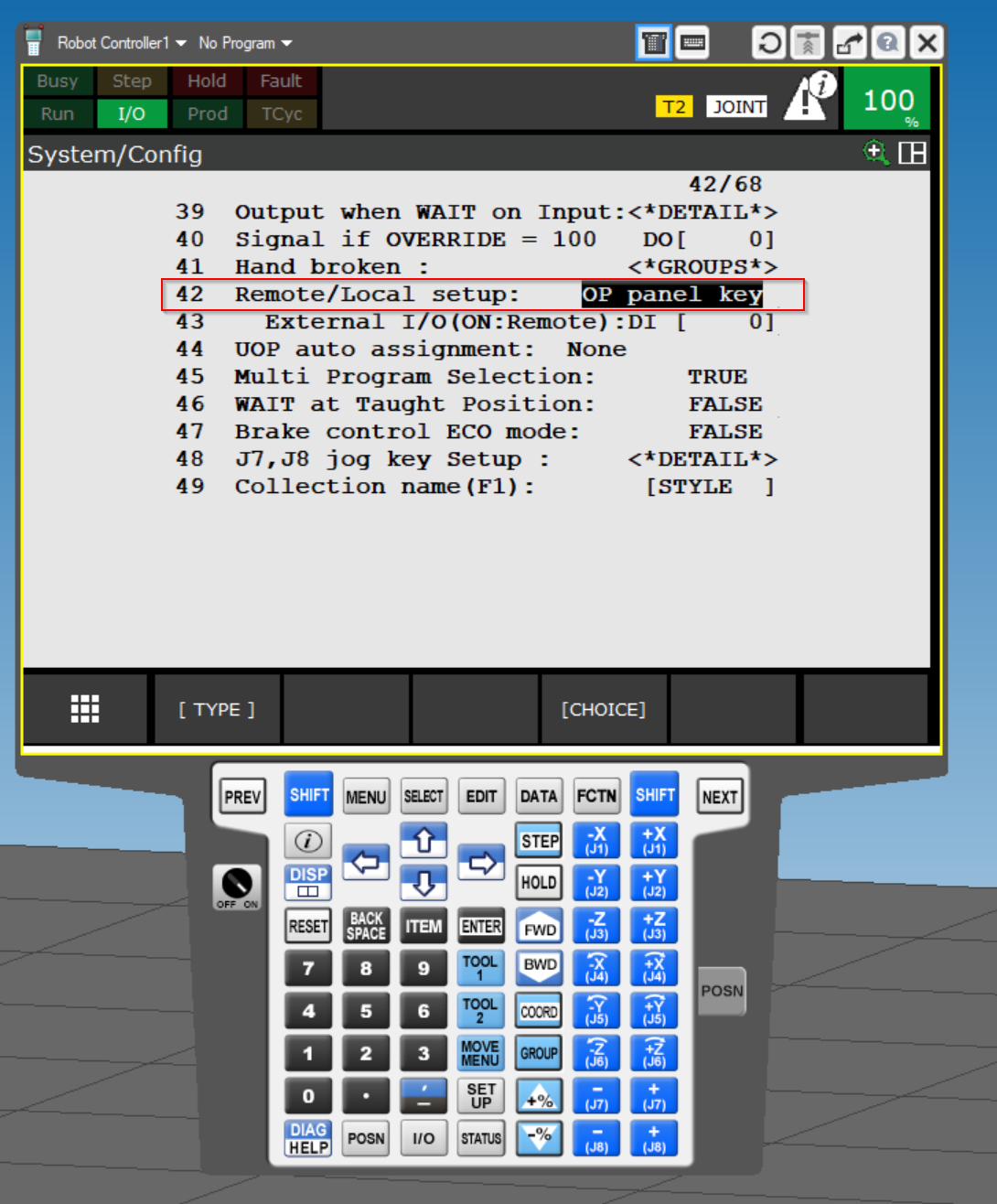
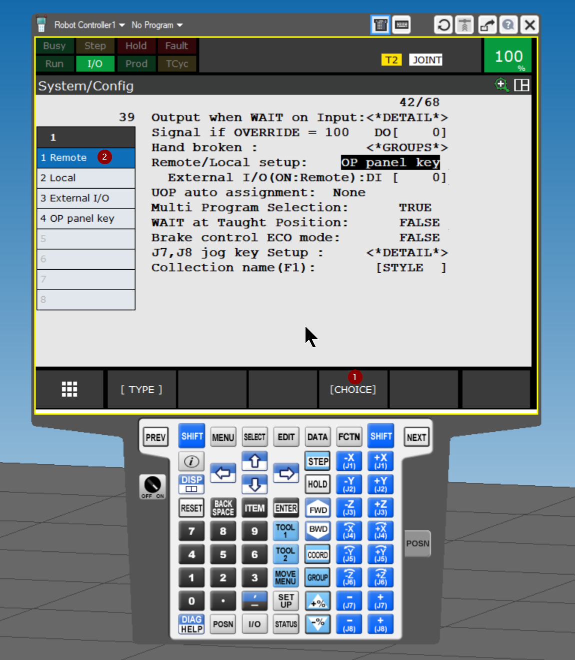
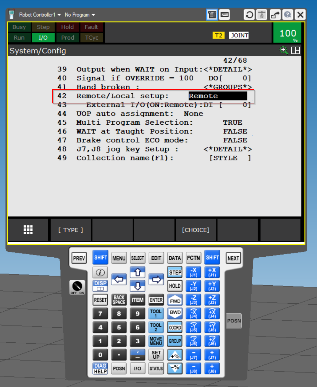
Click CHOICE and select Remote.
Done!
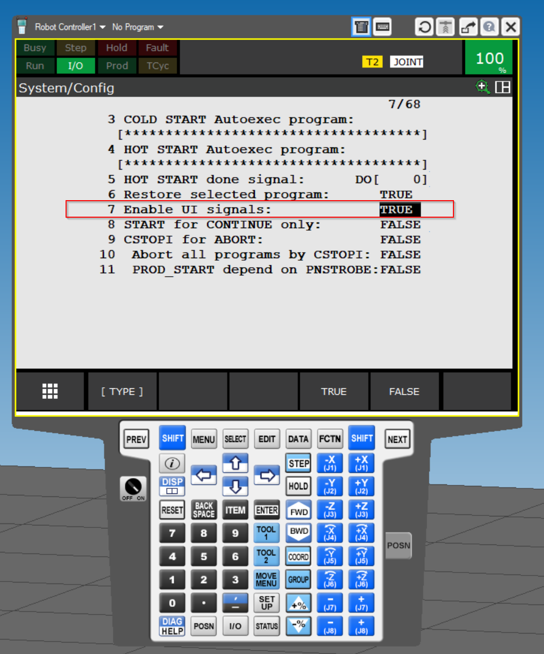
7 Enable UI signals should also be set to TRUE.
UOP
Next, open I/O>UOP to configure the UOP mapping settings.
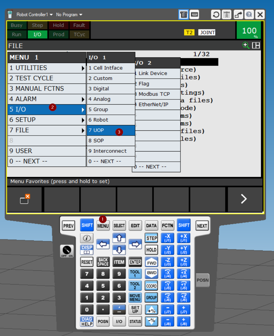
UO
The I/O UOP Out Monitor screen appears.
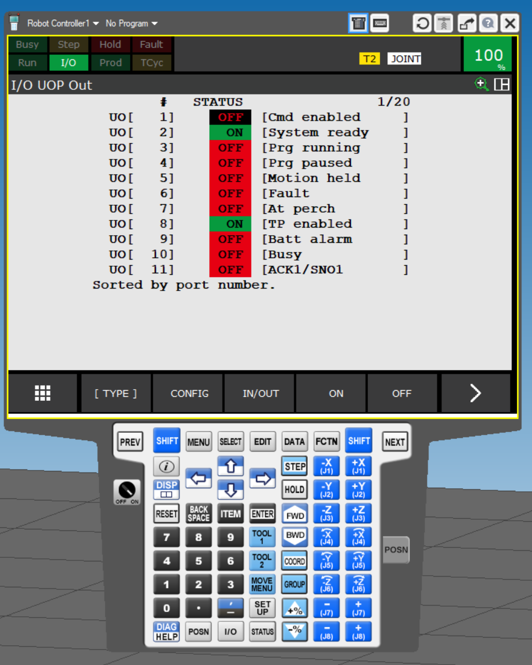
Click the CONFIG button and UOP also performs Mapping.
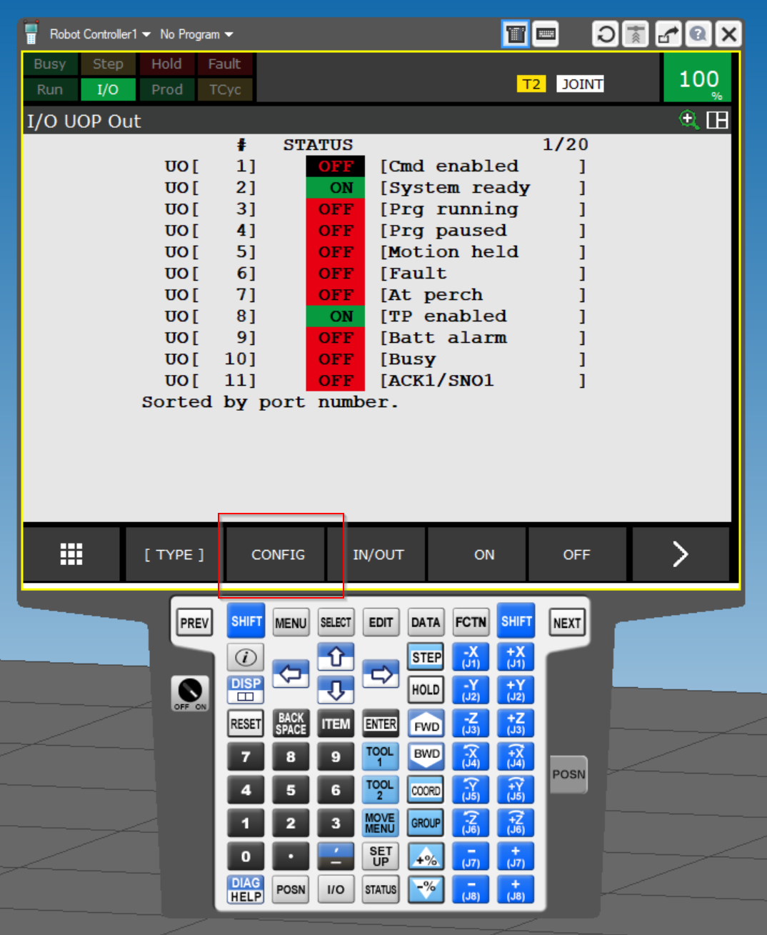
This is currently UO Mapping.
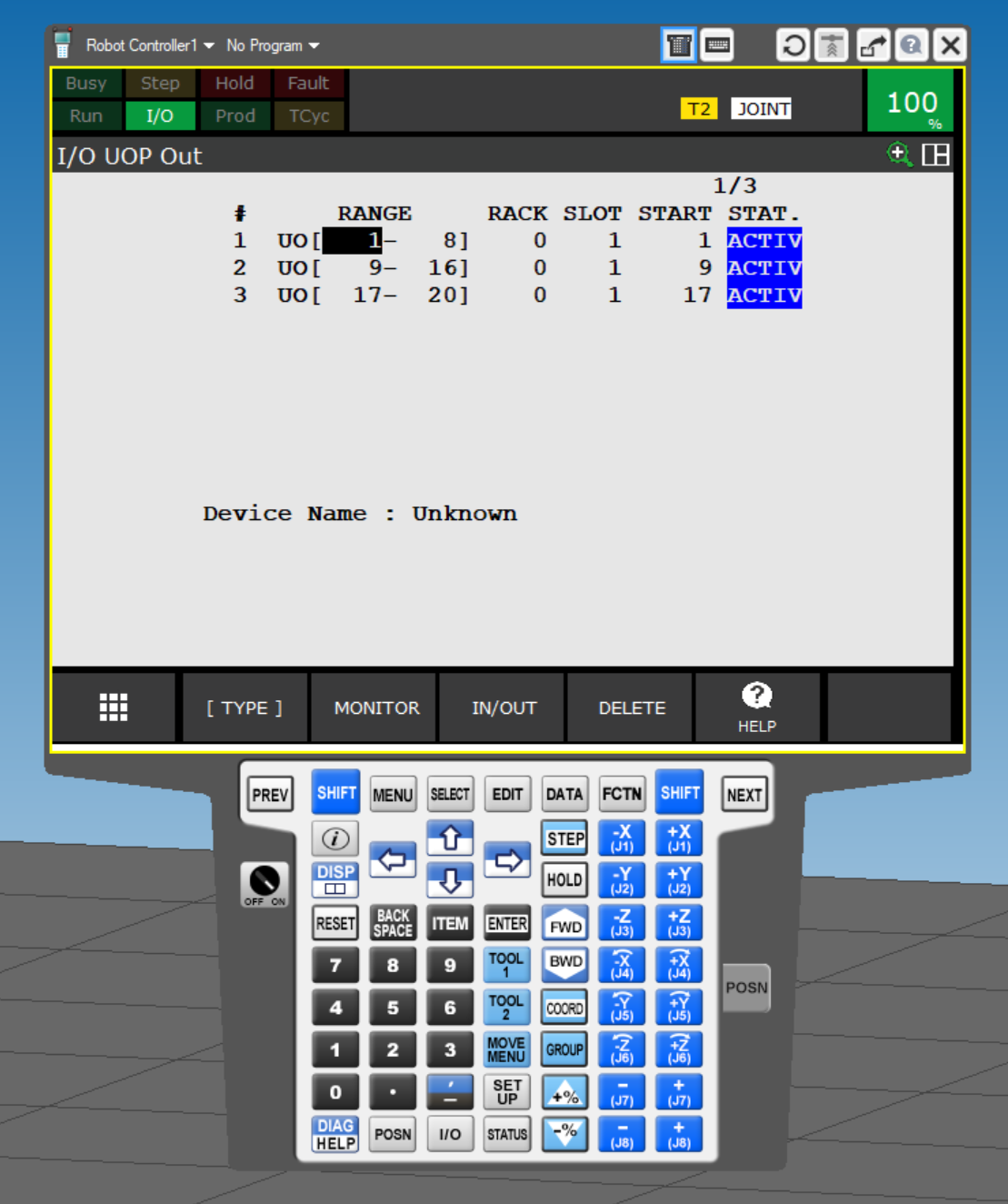
First, set the RACK value.
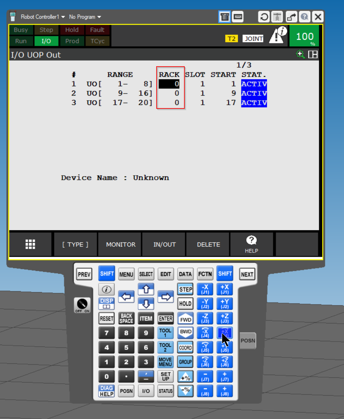
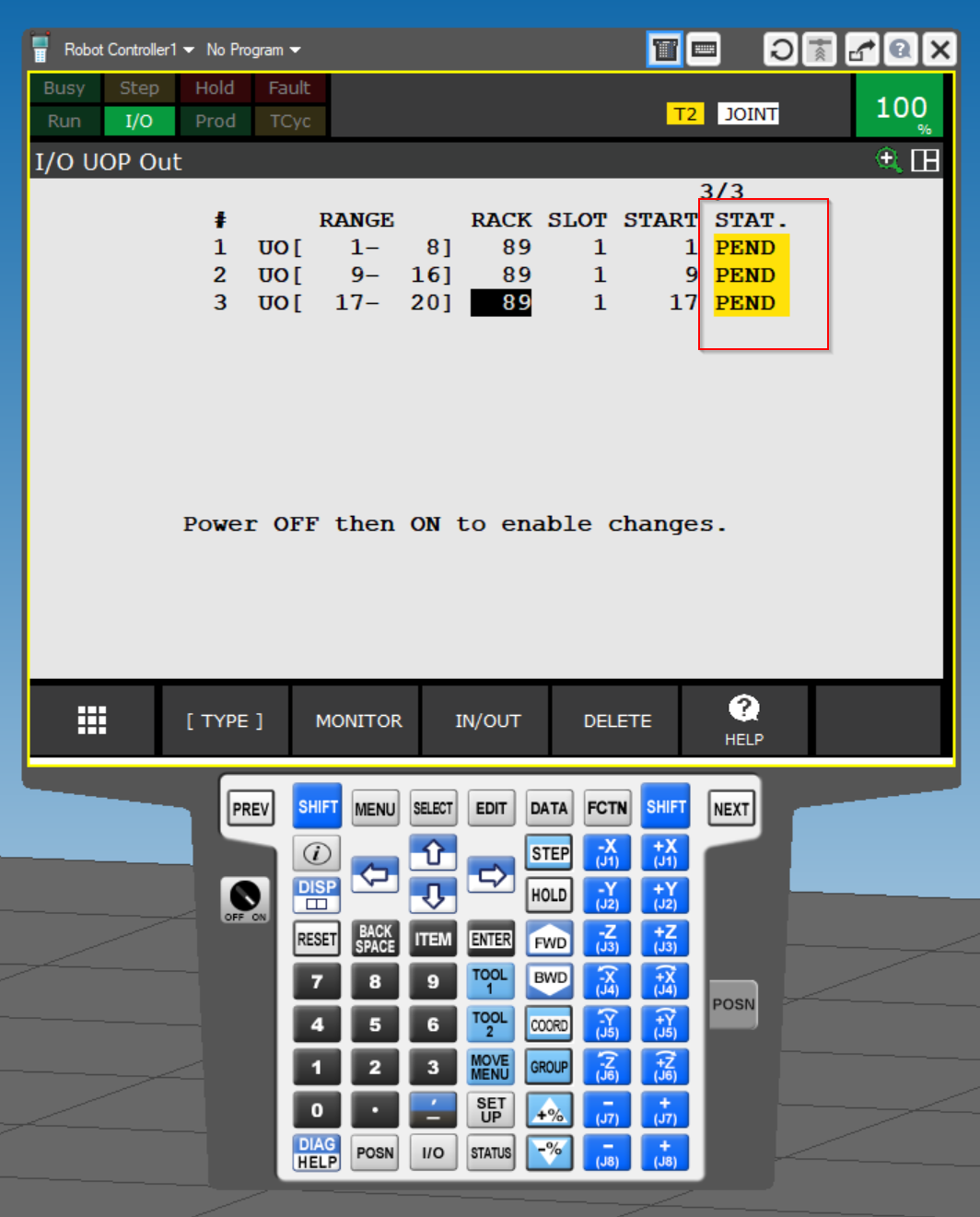
No. 89 is Ethernet/IP Rack, and STAT changes to PEND when the RACK of UO is changed.
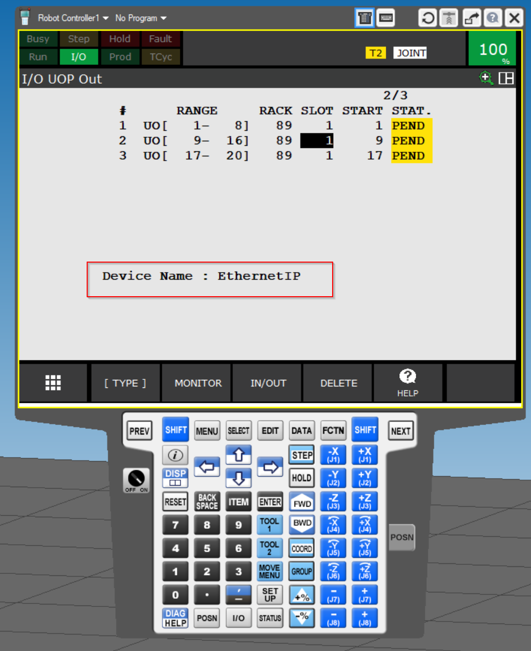
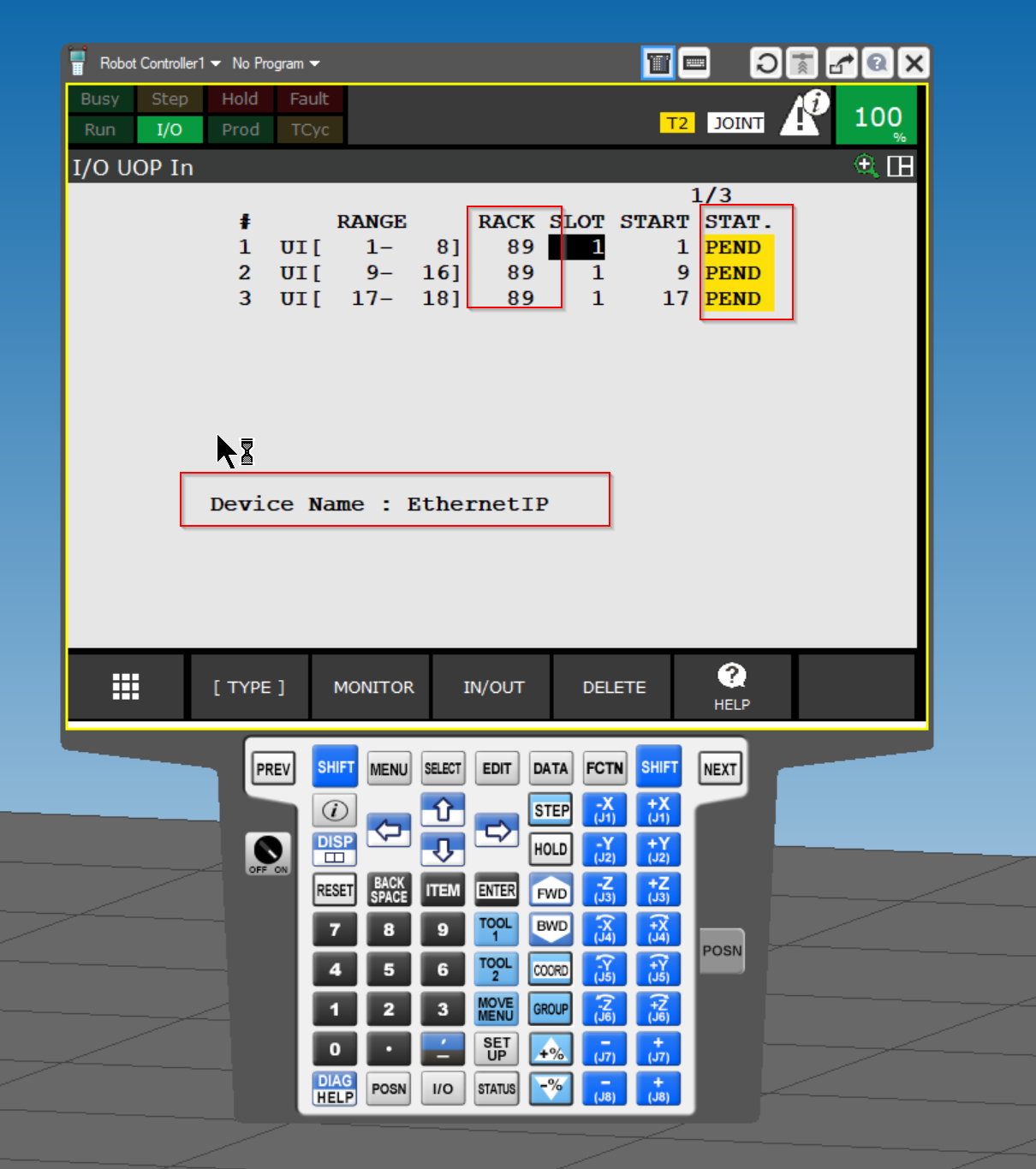
If the RACK, SLOT, and START values are set correctly, the Device Name will appear on the EthernetIP.
UI
Next, click on IN/OUT to configure the UI.
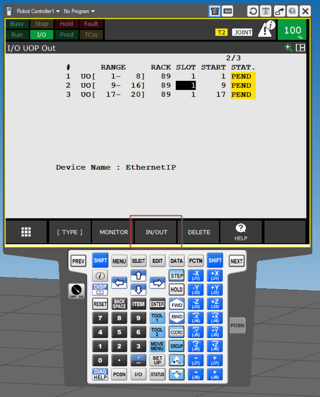
This is the UI settings screen.
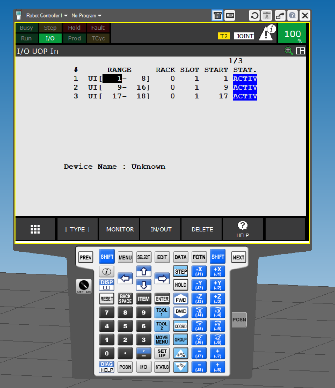
Also set RACK=89 and Slot=1, and START to 1,9,17.
STAT. will change to PENDING status.
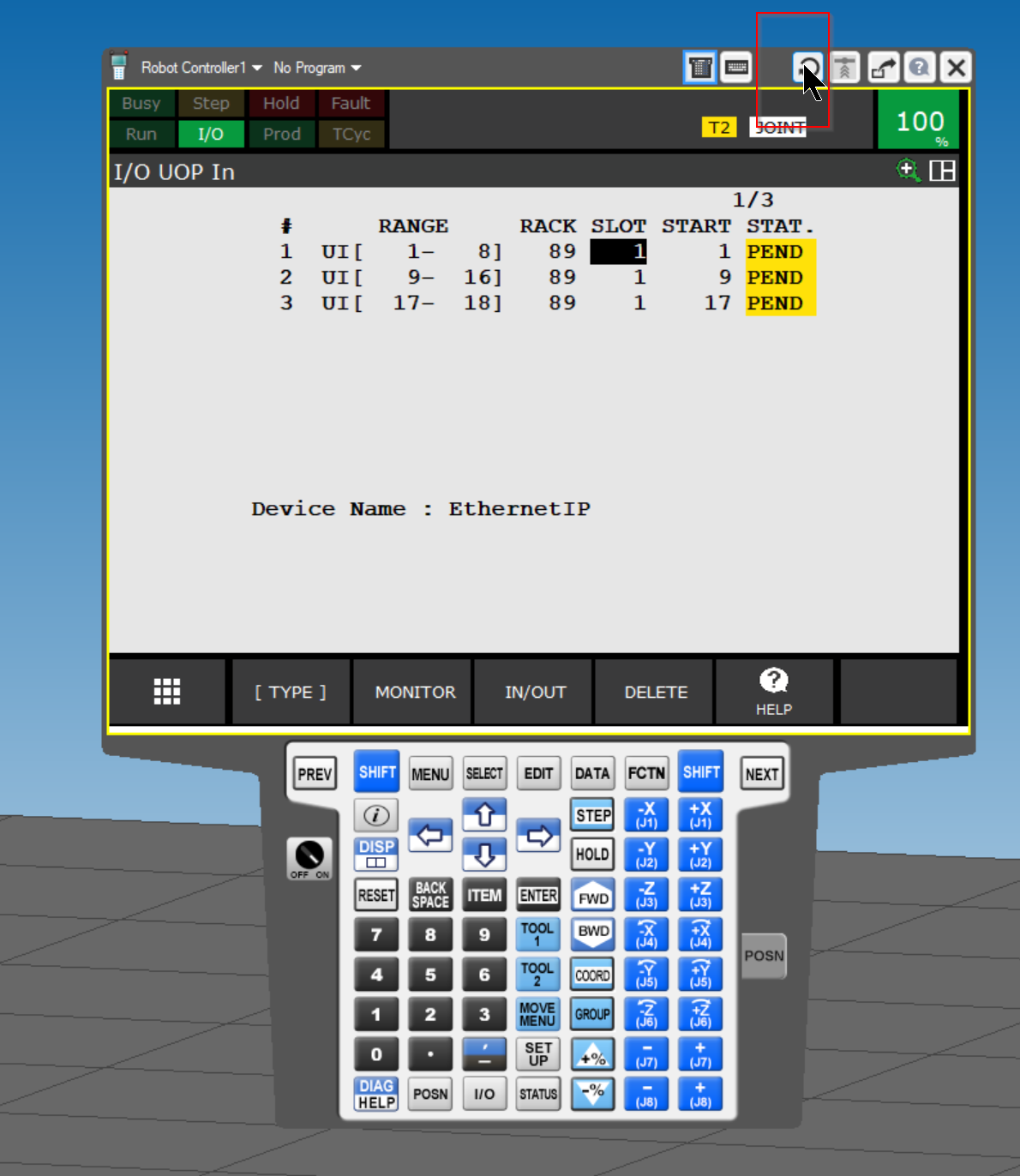
Restart Robot Controller.
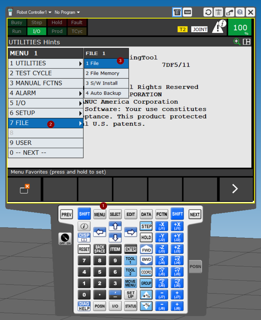
Export EDS File
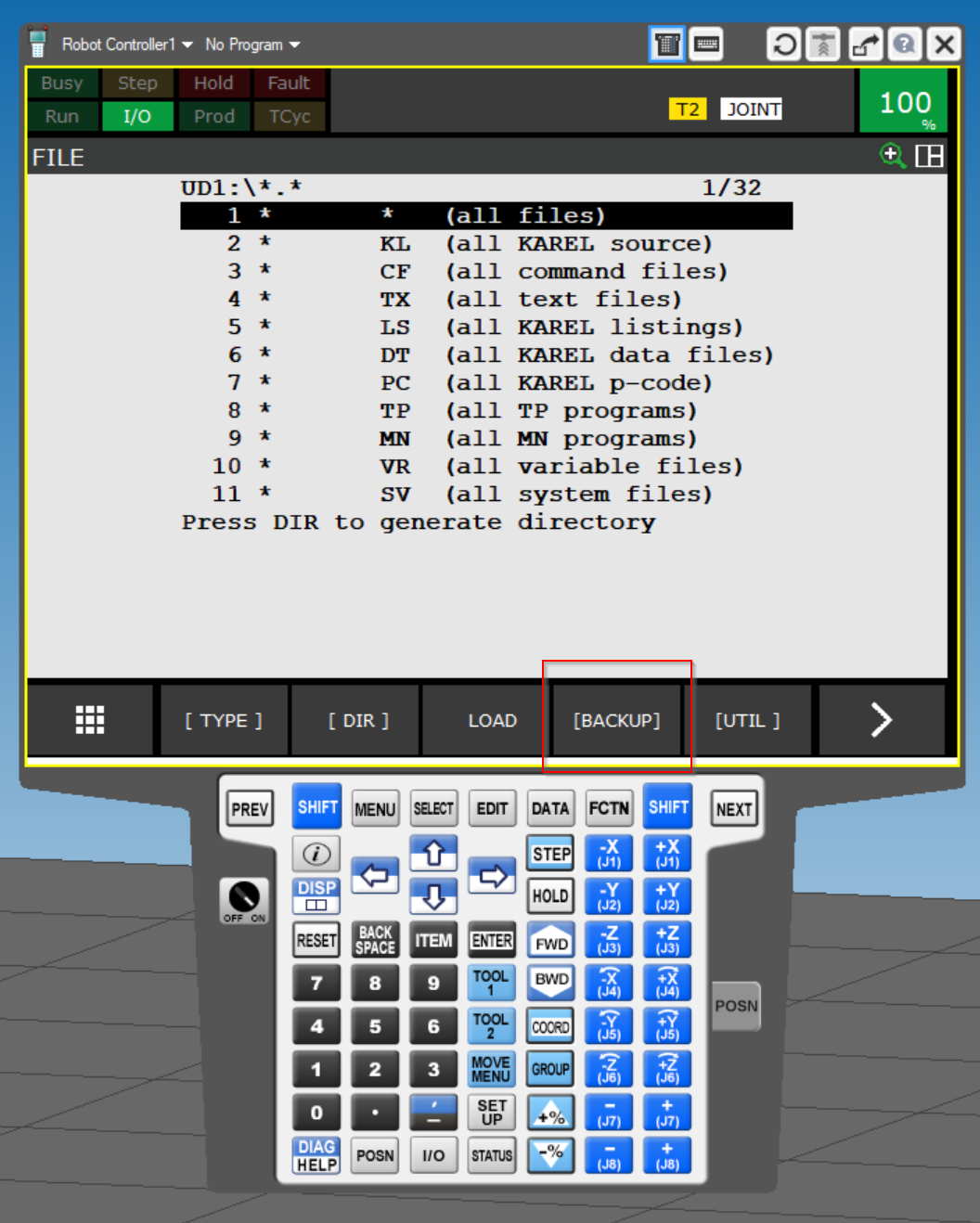
Open 7 FILE>1 File to Export EDS File to build Ethernet/IP Network.
Click BACKUP.
Click BACKUP 2>2 Com. Conf.
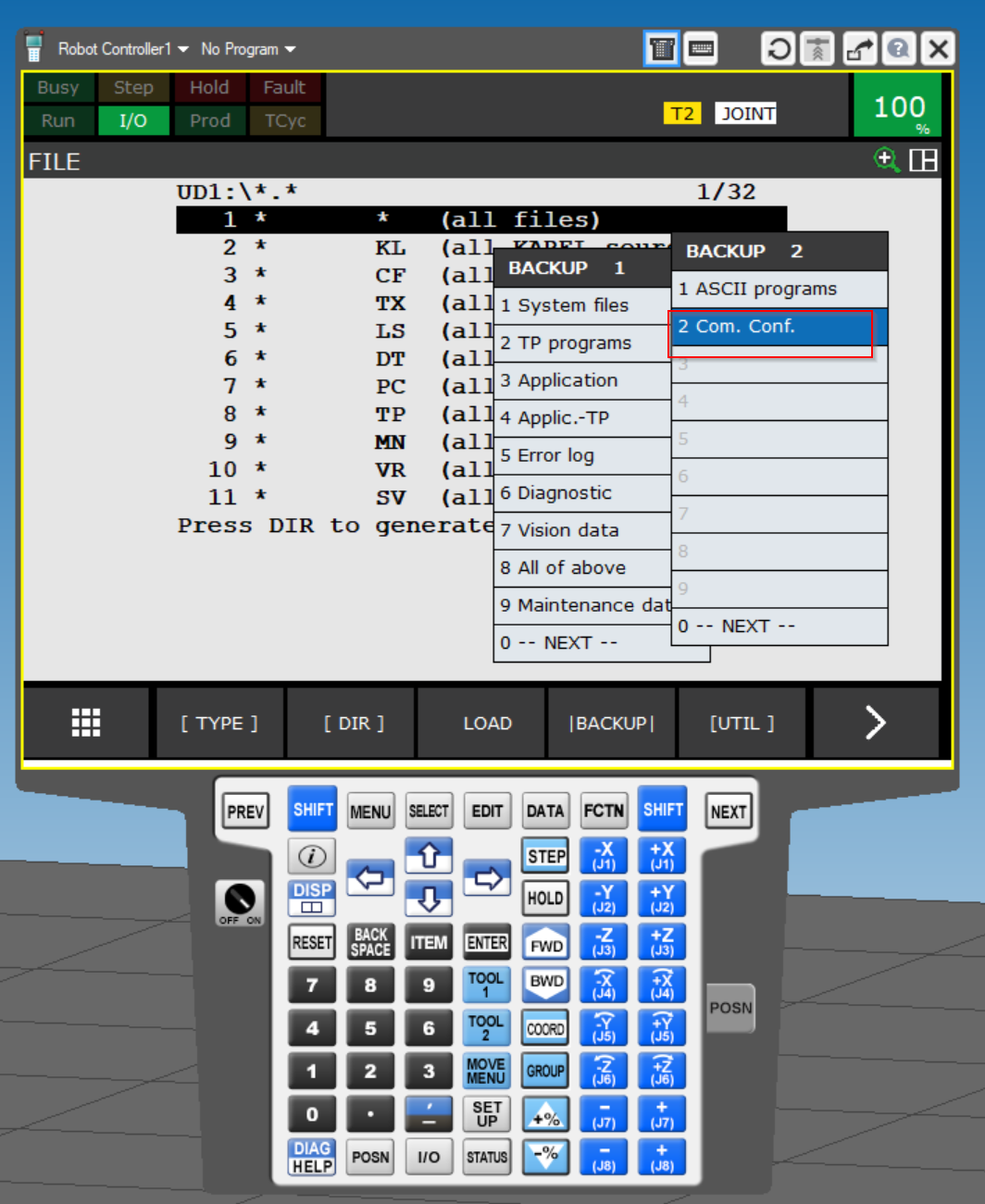
Done!EDS File has been Exported.

Now click on File>Explore Fodler>Your project Name Folder to open the location in ROBOGUIDE’s Project.
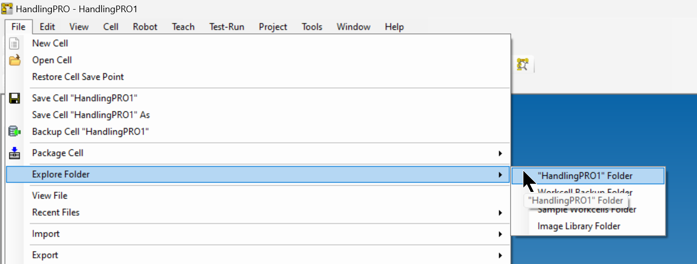
RobptGuide will automatically open the folder you are working on in Explore.
TwinCAT Side
The next step is to prepare the TwinCAT side. This article will first explain how to establish communication and MAPPING of UIO.

Install EDS File
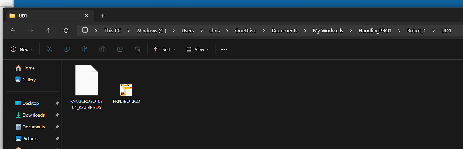
Store the EDS File you just exported from RoboGuide in the following Folder.
C:\TwinCAT\3.1\Config\Io\EtherNetIP
Add Ethernet/IP Scanner
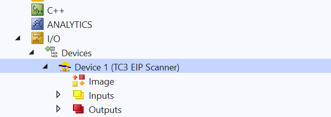
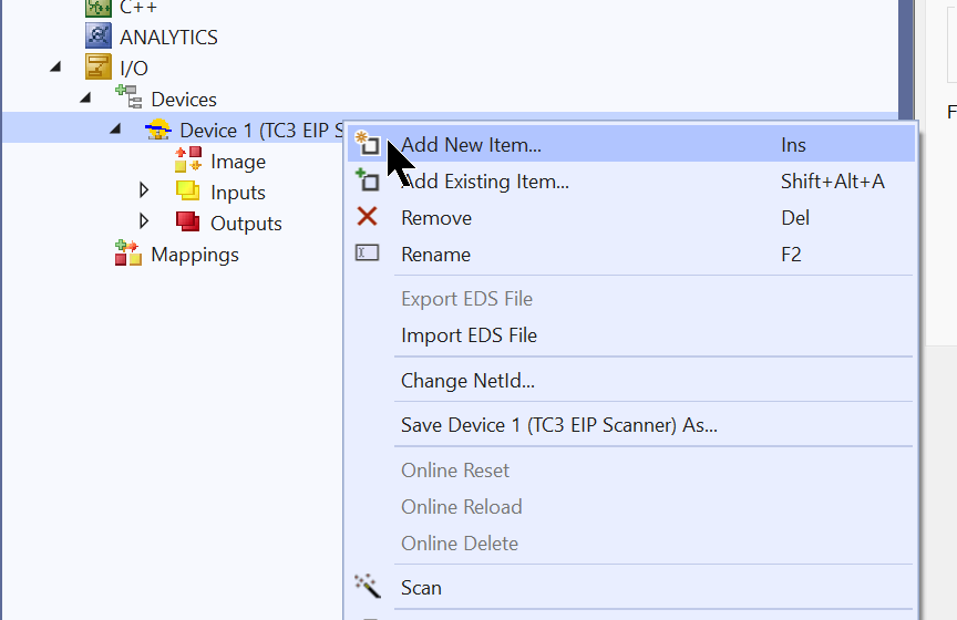
Add a new Fieldbus Driver under I/O>Devices>Add New Item.
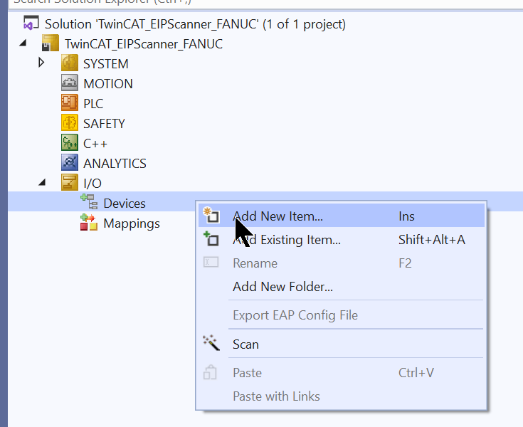
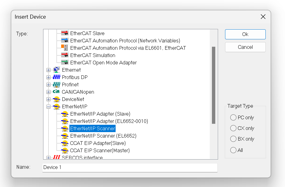
Select Etherent/IP>Ethernet/IP Scanner>Ok to proceed.
Open the Adapter’s Tab and click the Search button to set the Scanner Network Interface to be used as the Etherent/IP Scanner.
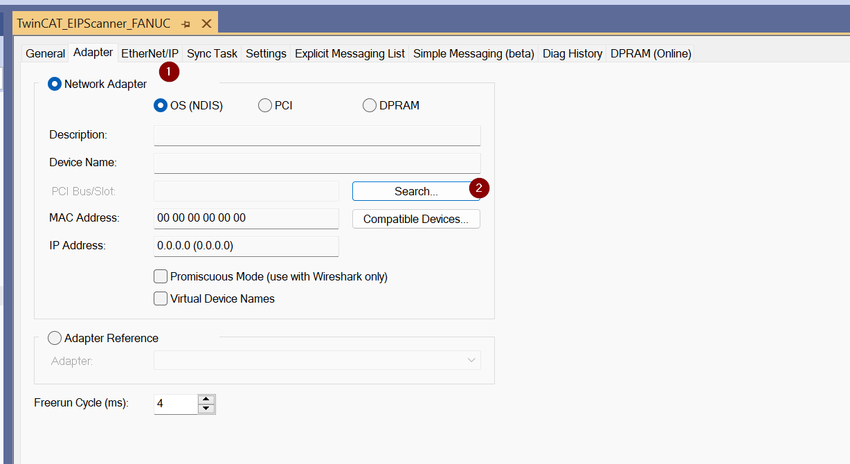
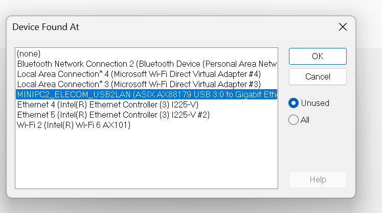
TwinCAT will list the Network Interfaces currently available on IPC.
Task
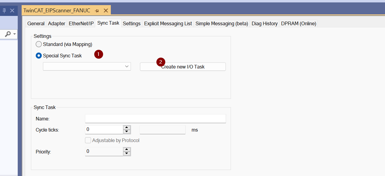
Next, open the Sync Task to add the Ethernet/IP Scanner Task.
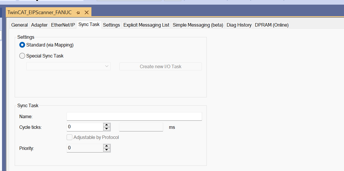
Select Special Sync Task > Create new I/O Task.
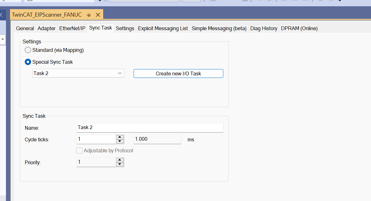
Enter a new Task name.
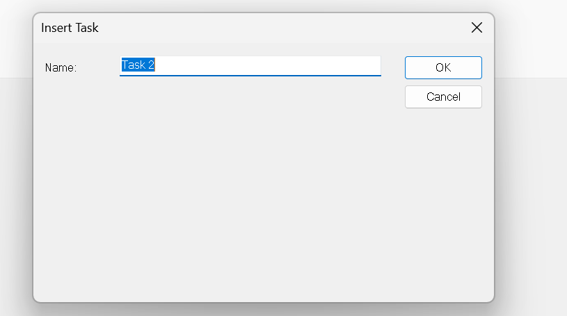
Done!
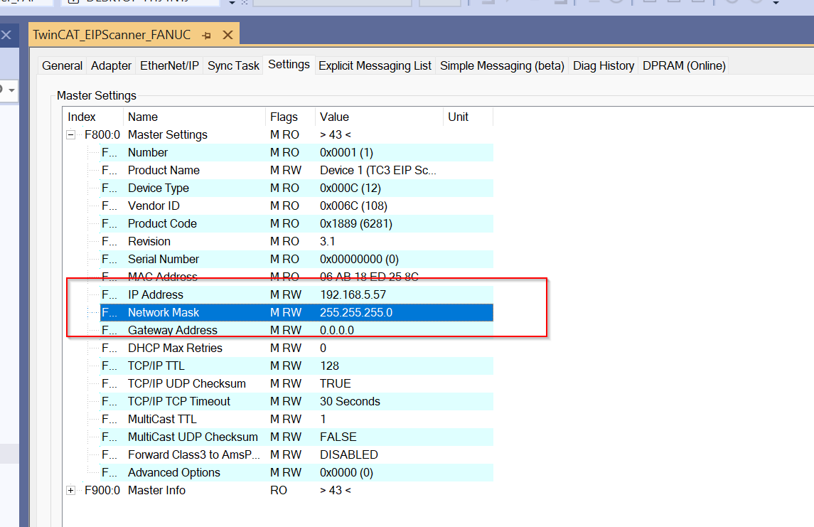
Scanner IP
Next, set the IP address of the Ethernet/IP Scanner. Click on the Ethernet/IP Scanner you just added.
Open the Settings Tab.
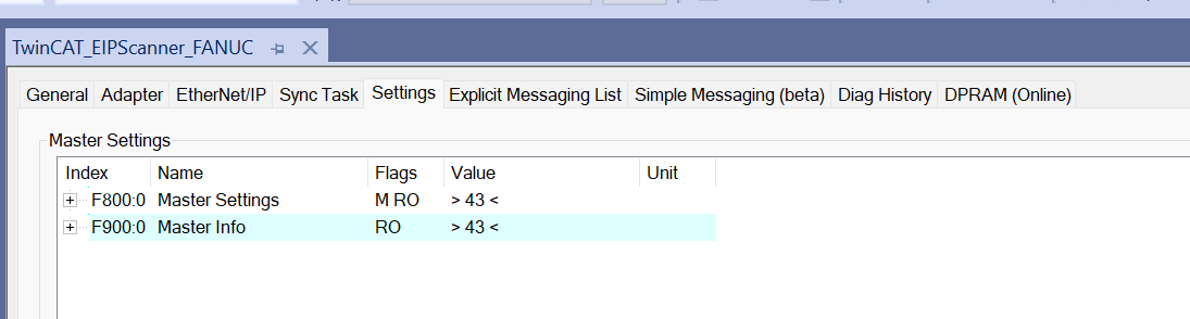
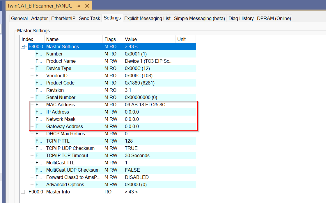
Done!
Add FANUC Adapter
Now that the Ethernet/IP Scanner configuration is complete, the next step is to add a FANUC Ethernet/IP Adapter. Right-click on the Scanner you have just configured>Add New Item.
Select FANUC Robot>Ok.
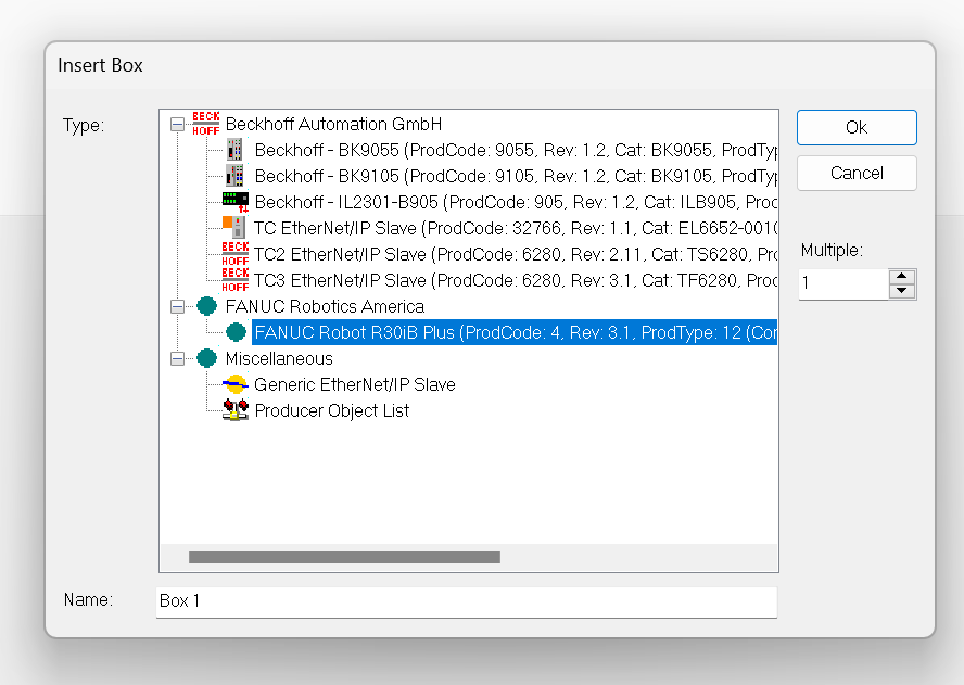
Done!
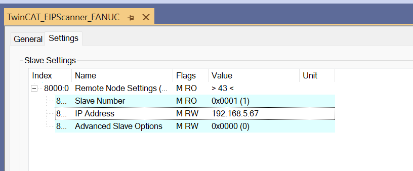
Adapter IP
Set the Ip address of the FANUC robot from Settings>8000.0.
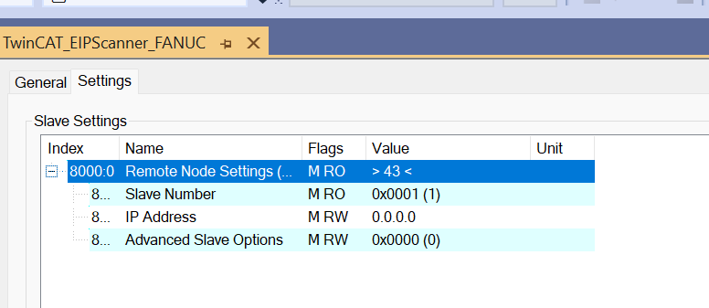
In this Tutorial, it will be 192.168.5.67.
Add Connection
Configure the Ethernet/IP Connection between Beckhoff TwinCAT3 and FANUC.
Right click on the FANUC Robot Adapter you just added>Append IO Connection>Adapter on slot1.
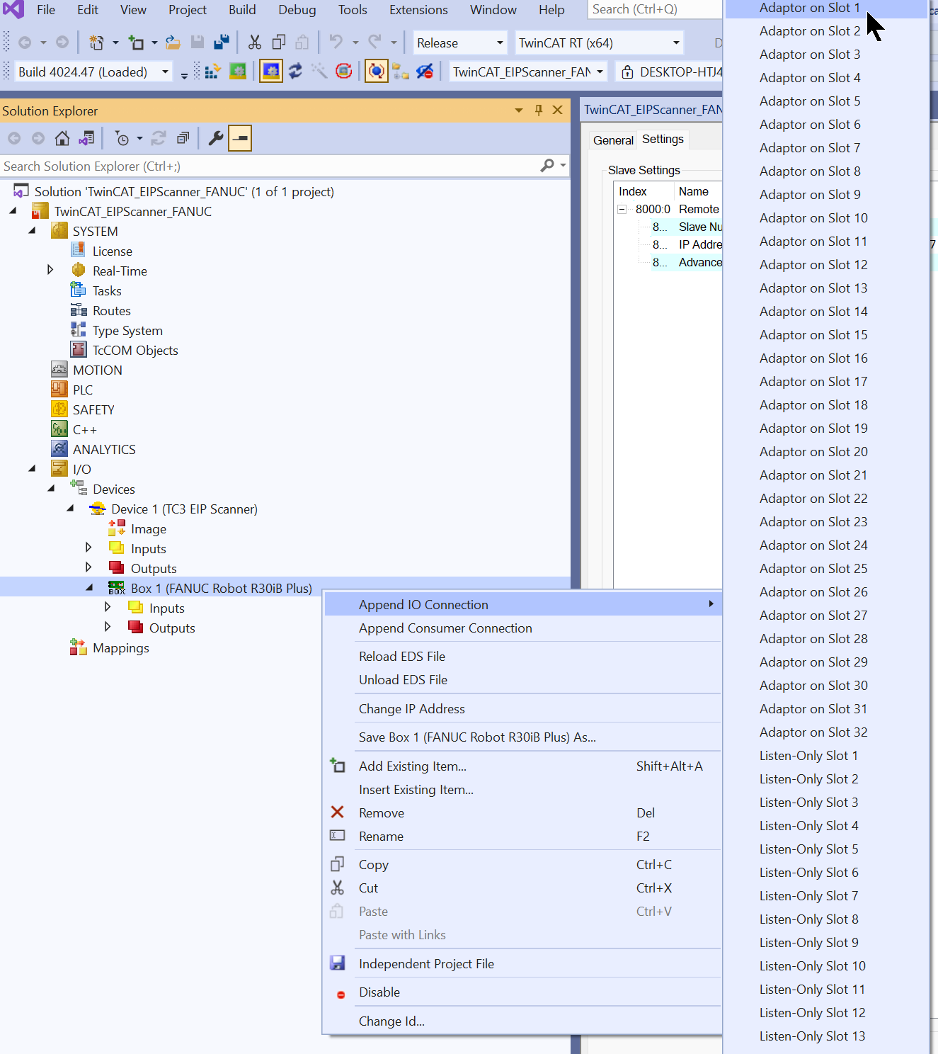
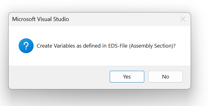
Press Yes.
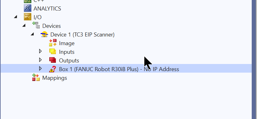
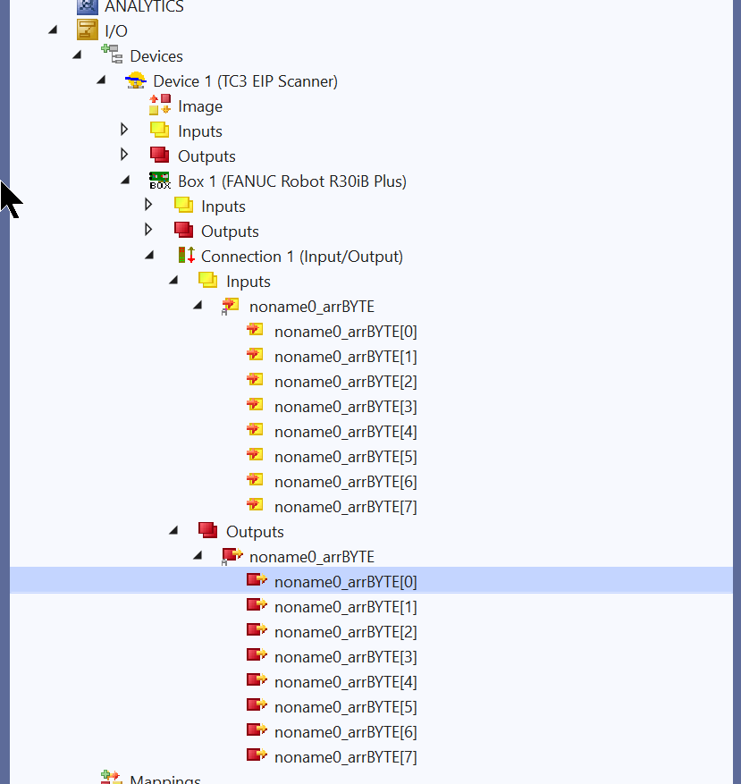
Done!Connection1 has been added.
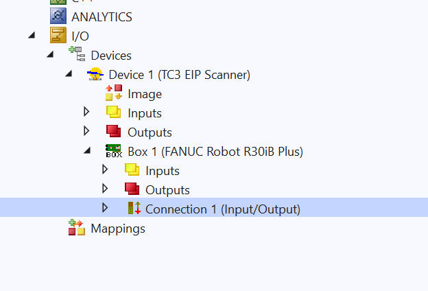
Inputs and Outputs match the variable sizes just defined in RobptGuide.
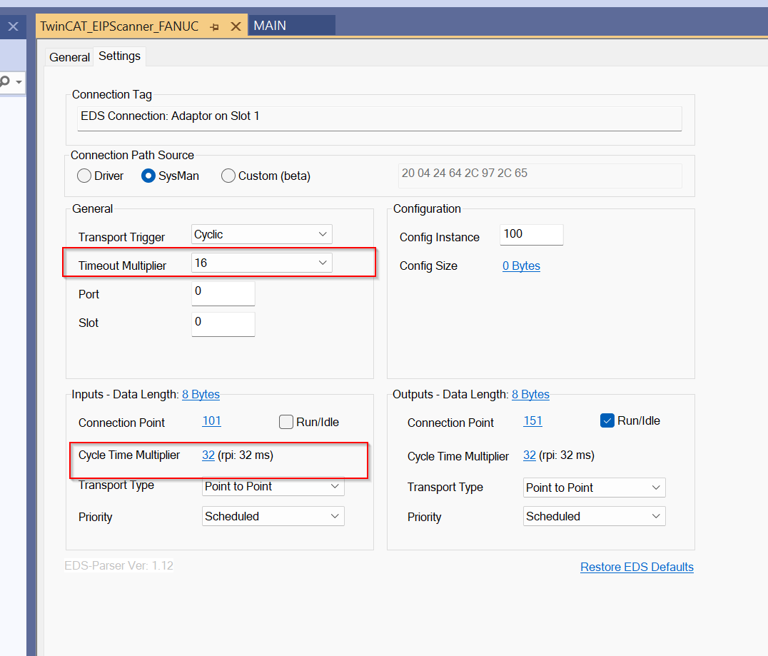
Configure
Since the connection settings were imported from the EDS File, there is basically no need to change the settings, but you should set the Timeout and RPI according to your application.
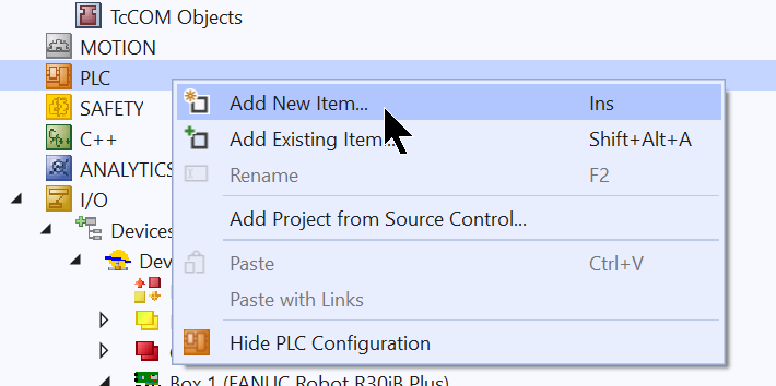
Add PLC
Now that you have finished setting up Fieldbus, the next step is to create a PLC program.
Go to PLC>right click>Add New Item.
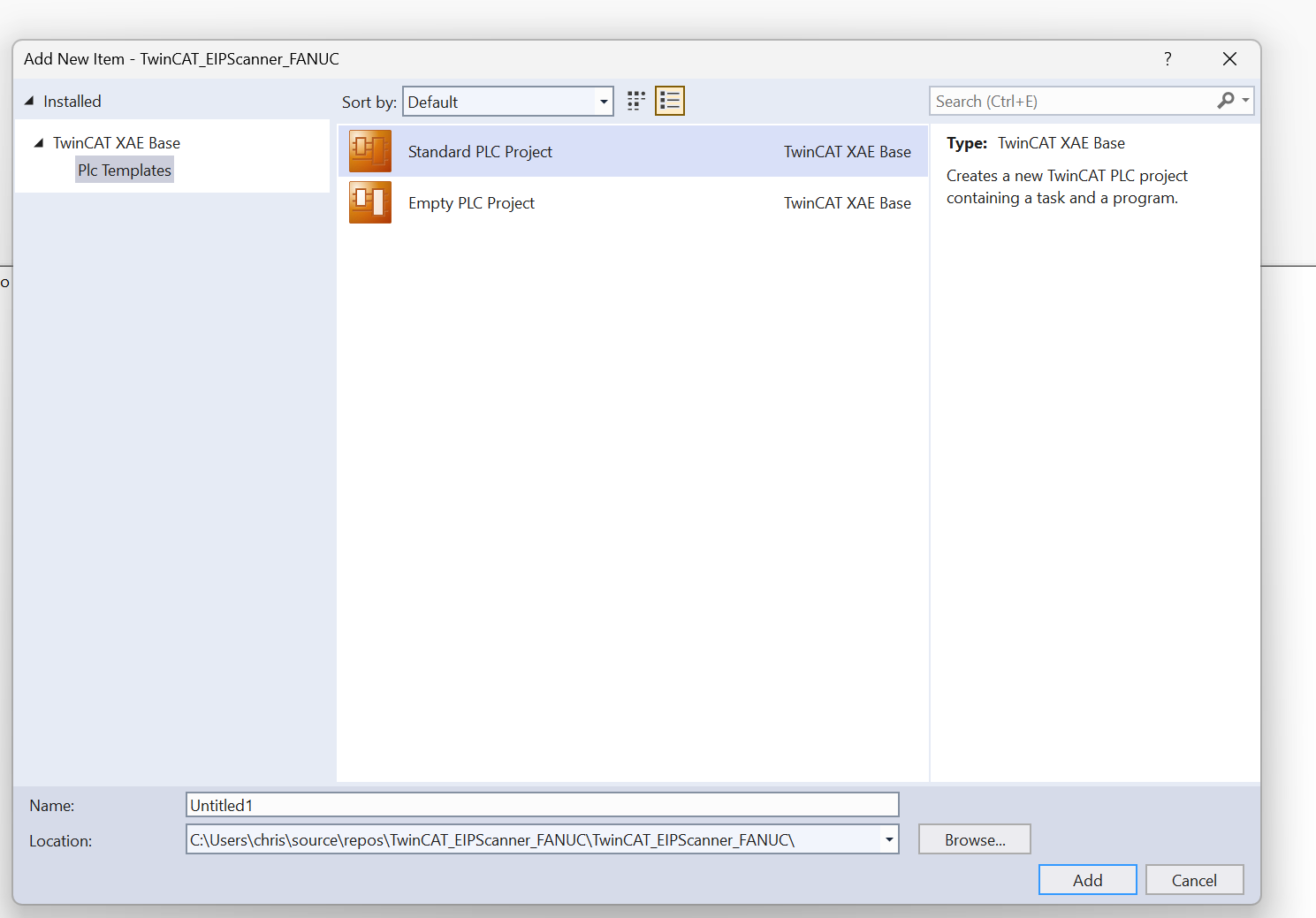
Select Standard PLC Project>Add.
Program
We will now create the structure and FUNCTION BLOCK.
DUT_FANUC_UI1
This is a structure created for FANUC’s UI1.
| TYPE DUT_FANUC_UI1 : STRUCT UI01_IMSP :BIT; UI02_Hold :BIT; UI03_SFSP :BIT; UI04_CycleStop :BIT; UI05_FaultReset :BIT; UI06_Start :BIT; UI07_Home :BIT; UI08_Enable :BIT; UI09_RSR1,UI10_RSR2 ,UI11_RSR3,UI12_RSR4 ,UI13_RSR5,UI14_RSR6 ,UI15_RSR7,UI16_RSR8:BIT; UI17_PNSStrobe:BIT; UI18_ProdStart :BIT; UI19,UI20,UI21,UI22 ,UI23,UI24,UI25,UI26 ,UI27,UI28,UI29,UI30 ,UI31,UI32 :BIT; END_STRUCT END_TYPE |
DUT_FANUC_UO1
This is a structure created for UO1 of FANUC.
| TYPE DUT_FANUC_UO1 : STRUCT UO01_CmdEnabled:BIT; UO02_SystemReady:BIT; UO03_PrgRunning:BIT; UO04_PrgPaused:BIT; UO05_MotionHeld:BIT; UO06_Fault :BIT; UO07_AtPerch:BIT; UO08_TPEnabled:BIT; UO09_BattAlarm:BIT; UO10_Busy :BIT; UO11_ACK1 :BIT; UO12_ACK2 :BIT; UO13_ACK3 :BIT; UO14_ACK4 :BIT; UO15_ACK5 :BIT; UO16_ACK6 :BIT; UO17_ACK7 :BIT; UO18_ACK8 :BIT; UO19_SNACK :BIT; UO20_Reserved:BIT; UO21,UO22,UO23 ,UO24,UO25,UO26 ,UO27,UO28,UO29 ,UO30,UO31,UO32:BIT; END_STRUCT END_TYPE |
FB_FANUC_Basic
This is the FUNCTION BLOCK that controls the FANUC robot.
| FUNCTION_BLOCK FB_FANUC_Basic VAR_INPUT END_VAR VAR_OUTPUT qEnable:BOOL; qFault:BOOL; END_VAR VAR _rawIn AT %I*:ARRAY[0..7]OF BYTE; _rawOut AT %Q*:ARRAY[0..7]OF BYTE; _EIPConnectionState AT %i*:UINT; _UI1:DUT_FANUC_UI1; _UO1:DUT_FANUC_UO1; END_VAR |
METHOD PUBLIC Enable
This Method enables the minimum necessary signals (IMSP, SFSP, ENABLE, HOLD) to ENABLE the FANUC robot.
| METHOD PUBLIC Enable : BOOL VAR_INPUT iTrigger:BOOL; END_VAR VAR _RobotEnable:BOOL; END_VAR _RobotEnable:=iTrigger AND NOT Fault(); _UI1.UI01_IMSP:=_RobotEnable; _UI1.UI03_SFSP:=_RobotEnable; _UI1.UI08_Enable:=_RobotEnable; _UI1.UI02_Hold:=_RobotEnable; |
METHOD PROTECTED Fault
This Method here outputs the Fault status of the robot by the Fault signal received from the FANUC robot.
| METHOD PROTECTED Fault : BOOL Fault:=_UO1.UO06_Fault OR _UO1.UO09_BattAlarm ; |
METHOD PUBLIC Rest
This Method resets FANUC robot errors.
| METHOD PUBLIC Rest : BOOL VAR_INPUT iTrigger:BOOL; END_VAR _UI1.UI05_FaultReset:=iTrigger; |
METHOD PUBLIC Update
The signal between the FANUC robot and TwinCAT is not updated unless this Method is called in the User program.
| METHOD PUBLIC Update : BOOL MEMMOVE( destAddr:=ADR(_UO1) ,srcAddr:=ADR(_rawIn[0]) ,n:=4 ); MEMMOVE( destAddr:=ADR(_rawOut[0]) ,srcAddr:=ADR(_UI1) ,n:=4 ); qEnable:=_UO1.UO01_CmdEnabled AND _UO1.UO02_SystemReady; qFault:=Fault(); |
MAIN
This is the MAIN program.
| PROGRAM MAIN VAR Robot1:FB_FANUC_Basic; bReset:BOOL; bEnable:BOOL; RobotEnable,RobotFault:BOOL; END_VAR Robot1.Update(); Robot1.Rest(iTrigger:=bReset); Robot1.Enable(iTrigger:=bEnable); RobotEnable:=Robot1.qEnable; RobotFault:=Robot1.qFault; |
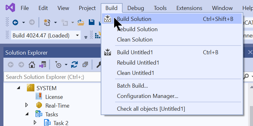
Build
Compile the project under Build>Build Solution.
Link
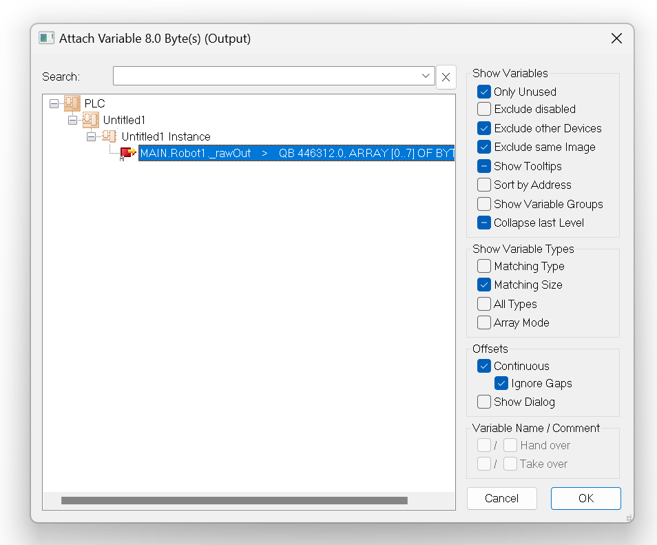
The last step is to map the variables and Process Data in the User program by clicking Inputs>Select All>Change Multi Link.
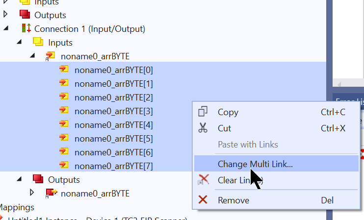
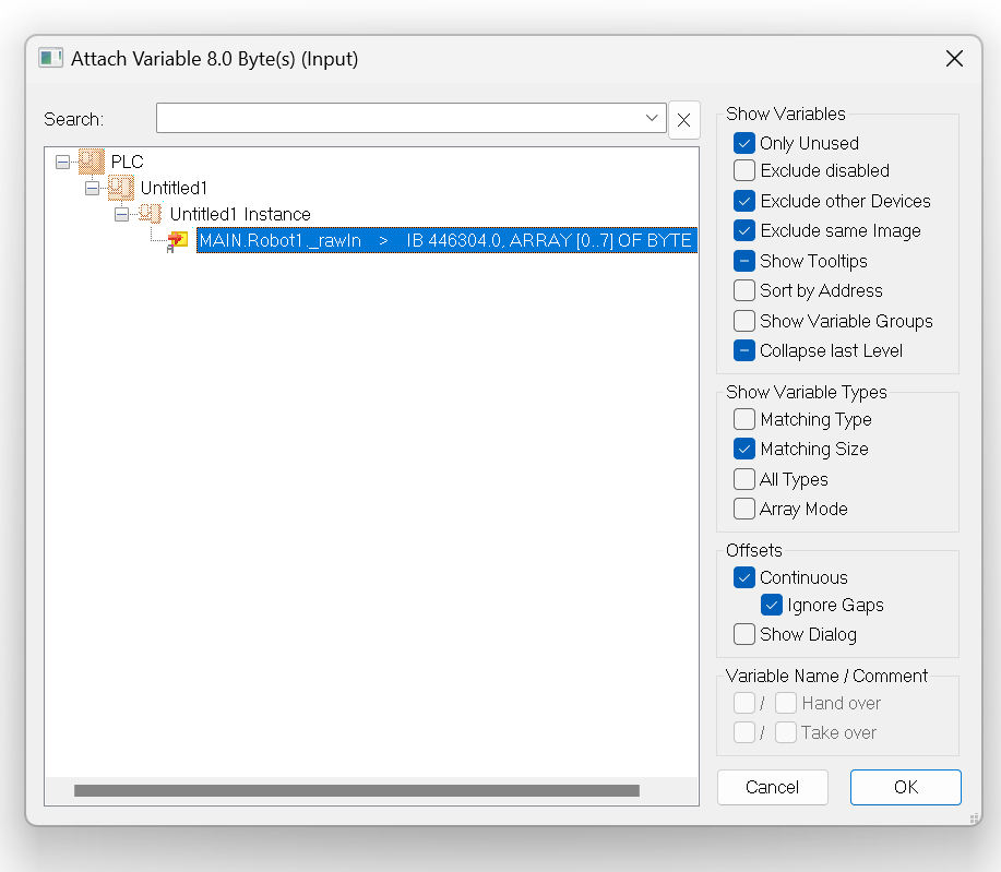
The Function Block we just created has Process Input defined as %I*, so let’s select this variable.
Click Outputs>Select All>Change Multi Link.
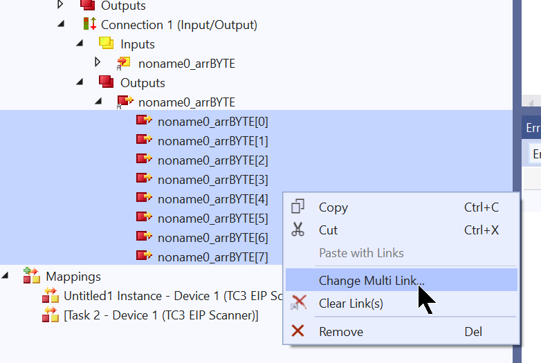
The Function Block we just created has a Process Output defined as %Q*, so let’s select this variable.
Download
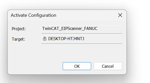
The last step is to Download the project to Runtime in Activate Configuration.
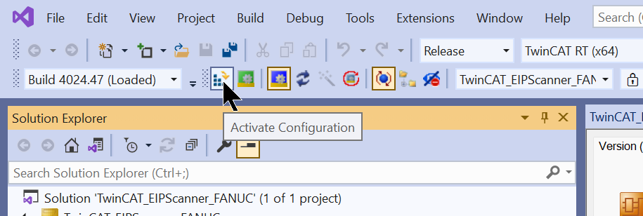
OK to proceed.
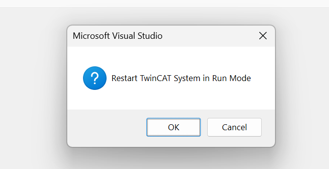
Switch TwinCAT to Run Mode.
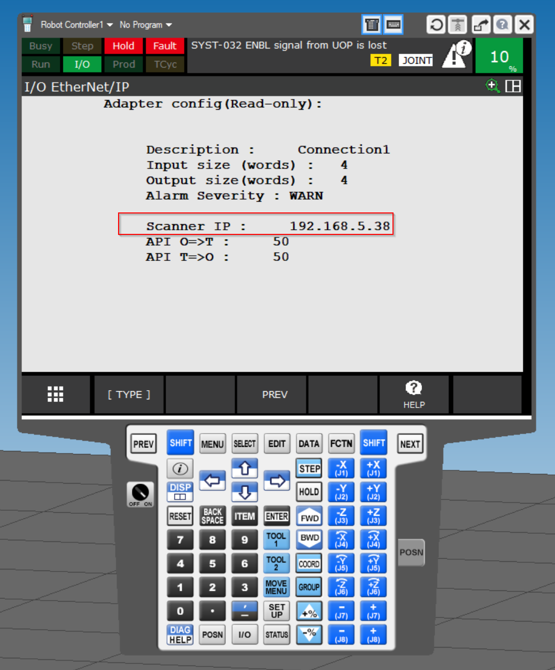
Result
First, let’s check from the FANUC robot side: the Adapter displays the Scanner IP, which is the Scanner IP address of the Beckhoff TwinCAT3.
This video shows the operation to Enable the FANUC robot from TwinCAT.
ROBOGUIDE.Enable robot From TwinCAT via Ethenret/IP
This video shows the operation to Disable the FANUC robot from TwinCAT.
ROBOGUIDE.Disablerobot From TwinCAT via Ethenret/IP
This video shows the operation to reset the FANUC robot error from TwinCAT.
コメント
Hello, I am training robotics and would like to know how I am able to read registers and alarms from FANUC using beckhoff PLC with Ethernet/IP. Could you help me with this? I think it is the CustomService I should use.