This is the fourth episode of the Visual Components Tutorial. This time we will introduce the Robot Transport Controller.
Let’s get started!

Target
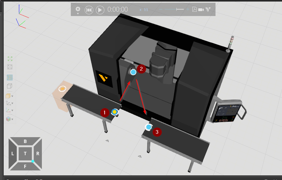
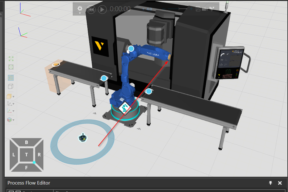
Here is the result of this Tutorial. The robot grabs things from the Conveyor, puts them in the Machine Center, and finally carries them to another Conveyor.

Reference Link
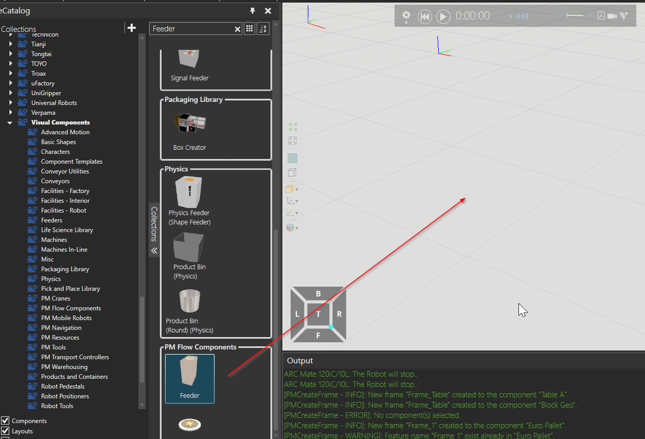
Insert Feeder
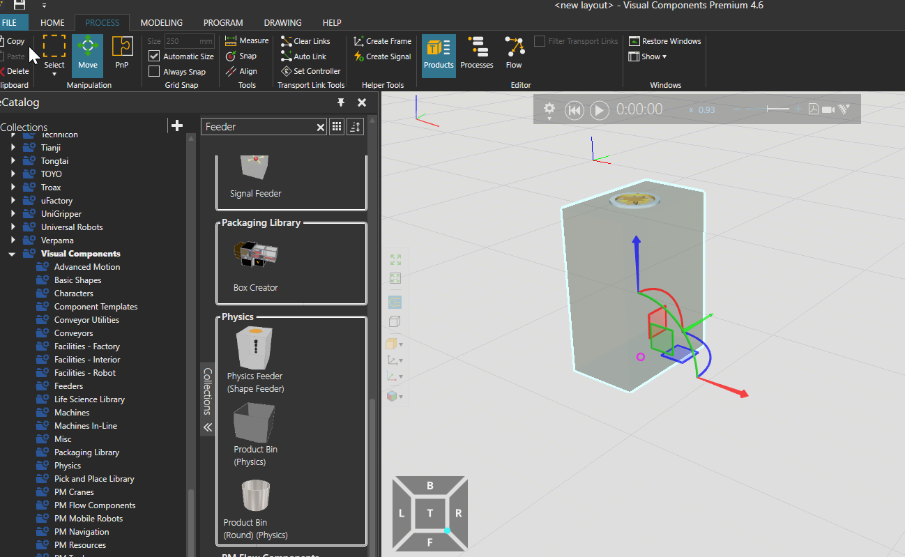
Add a Feeder to generate the Part.
Done! Parts generated from this Feeder, finally picked by the robot > put in the Machine Center.
Link to the Coveyor
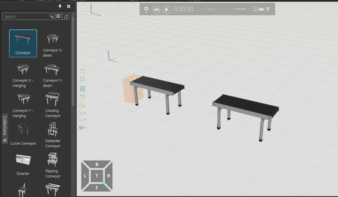
Next, add a Conveyor and link the Feeder and Conveyor.
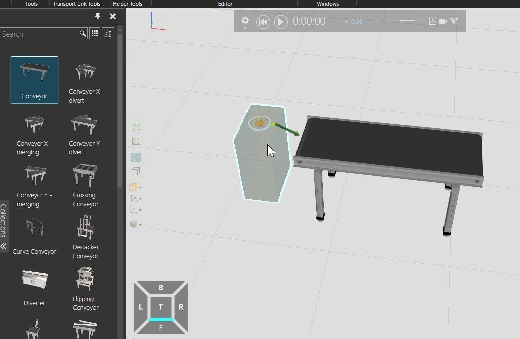
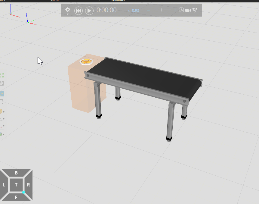
Done! Now the Parts generated from the Feeder are flowing to the Conveyor.
Add another Conveyor. This Conveyor is used for the robot to take out the finished parts from the Machine Center and transport them to the next process.
Add Machine Center
Add Parametic Vertical Mill to your project from Collections>Machines.
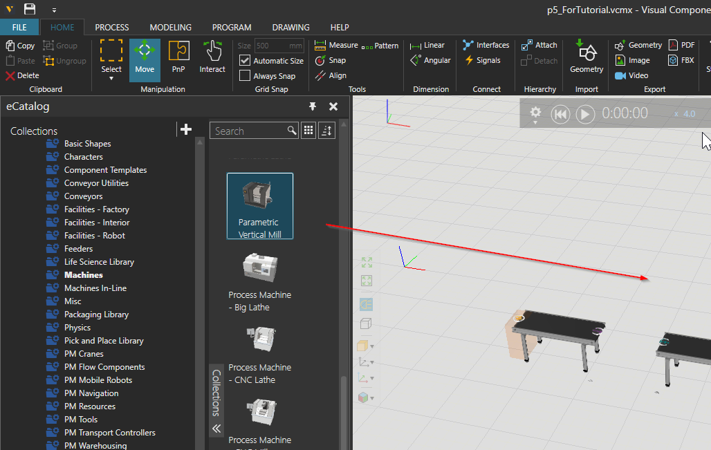
Done! The basic Layout of the machine has been built.

Edit Flow
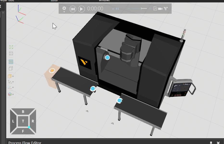
Click FLOW from the Tool Bar in PROCESS.

A blue point appears from each component.
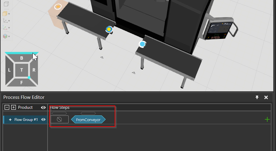
If you move the mouse to the blue point at the exit of the Conveyor, you will see “FromConveyor”. This means that parts flowing from this Conveyor on the Flow can flow to another part when they arrive at this blue point.
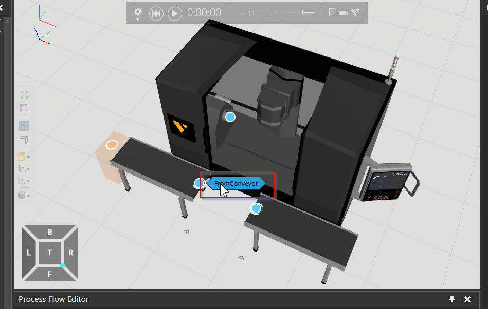
Clicking on the blue dot “FromConveyor” will add it to the Process Flow Editor and “FromConveyor” to the Flow Steps.
Configure the Flow
Let’s Consider the Flow of Simulation. Parts are transported to Conveyor 1 and machined at the Machine Center. Then the processed parts are transported from Conveyor 3 to another process, and so on.
Visual Components can build a Flow between parts with a simple Click operation as shown in the figure below.
Play
Check the Flow with the Play button.
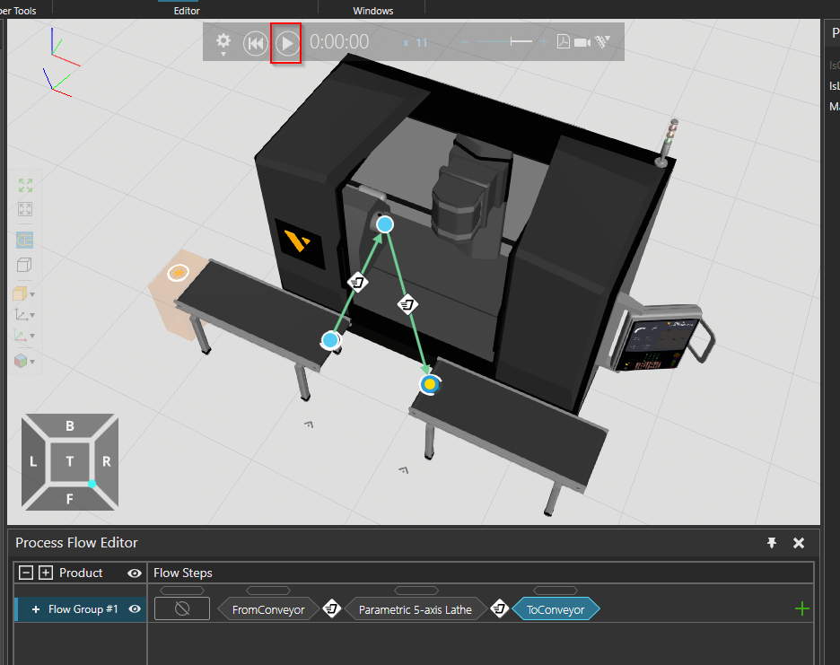
Done! Parts now flow from Conveyor 1 > into Machine Center and move to > Conveyor 2.
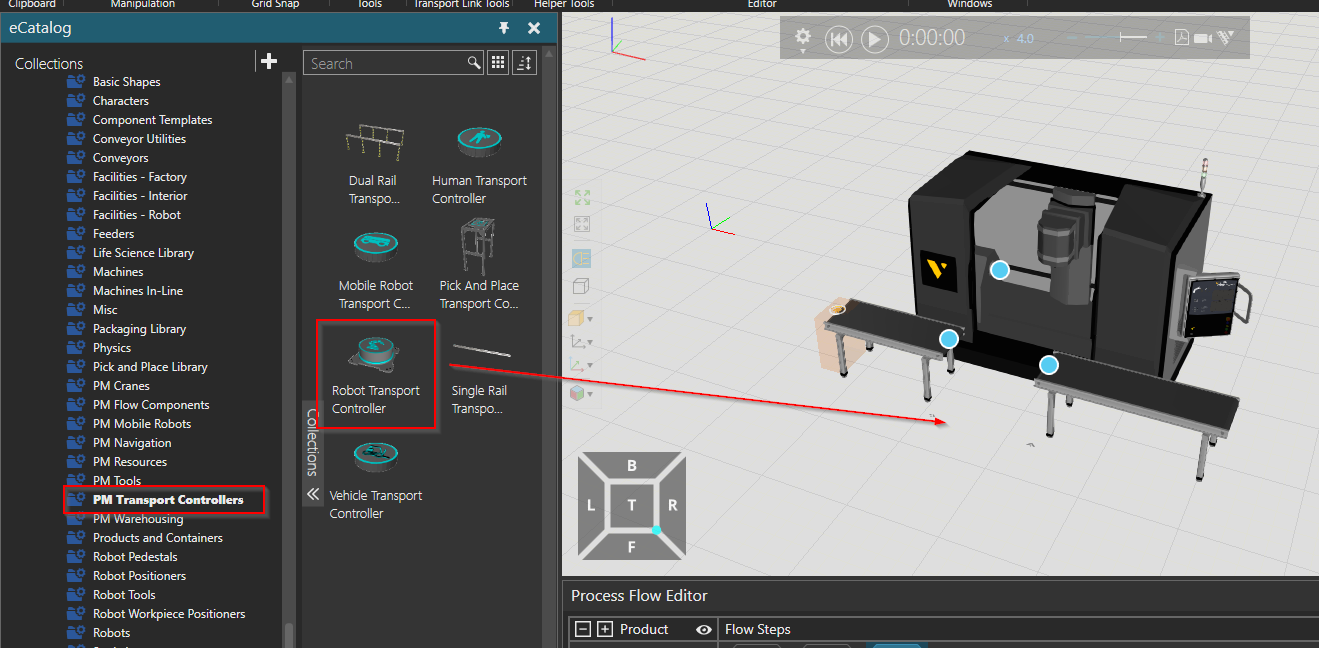
Robot Transport Controller
Next, add PM Transport Controllers>Robot Transport Controller from Collections.
The Robot Transport Controller is a component that allows easy control of Flow via a robot.
Done!
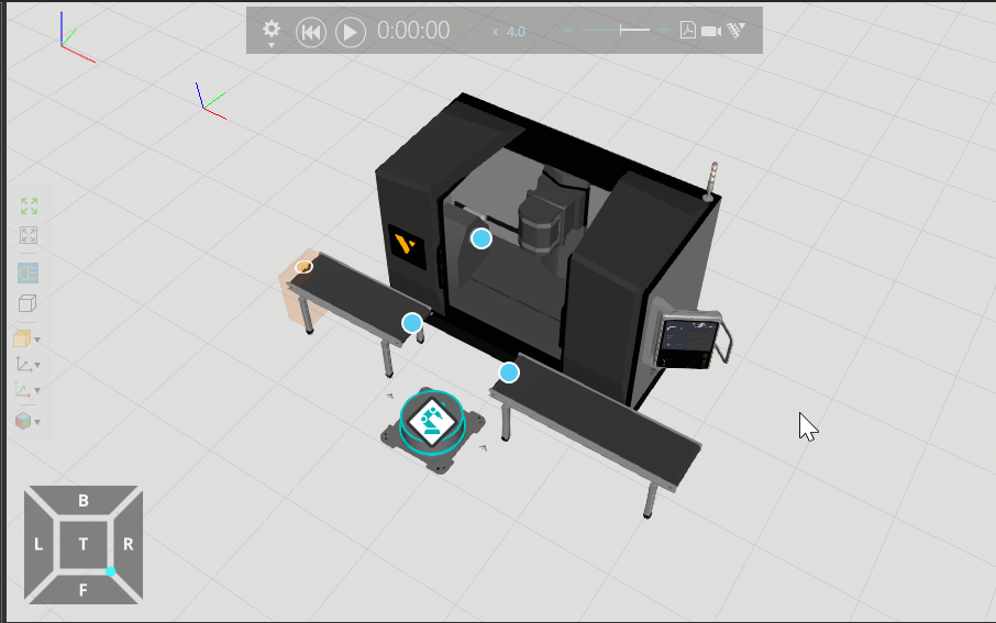
Add Robot
Next, we can add a robot.

Connect
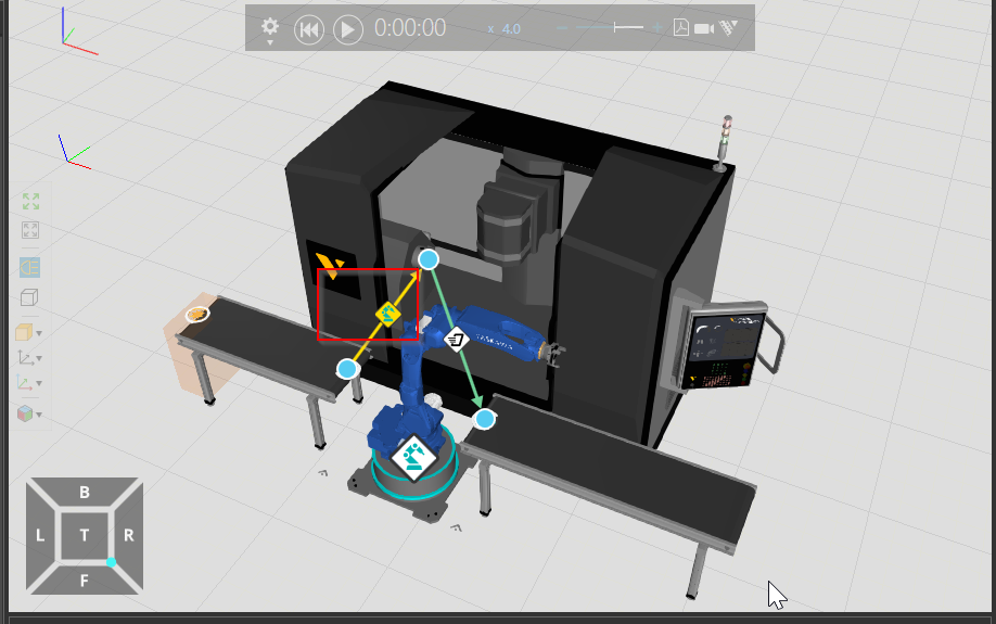
In this Flow, the robot transports the parts from Conveyor 1 to the Machine Center, and then brings the processed parts to Conveyor 2, right? So, let’s connect the robot to the Robot Transport Controller.

The operation is as shown in the figure below.
Add Tools
We need Tools to grab the Parts, Let’s add a Gripper from Collections.

The Tool is then connected to the robot.
Done!

Edit the Flow
Finally, we can edit the Flow. please click on the two Steps in the Flow Step.

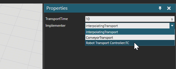
In the Properties screen, there is an item called Implementer.
From this item, you can configure the parts that implement the movement between Flows.

From Drop-List to Robot Transport Controller:TC.
Done!Flow Step’s Icon has been replaced by a robot.
Done!

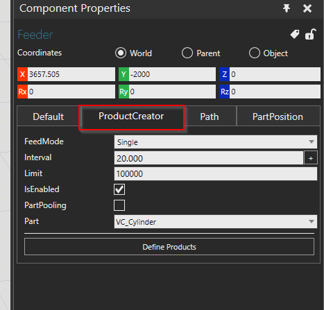
Configure Feeder
The last step is to set the speed at which the Feeder generates parts.
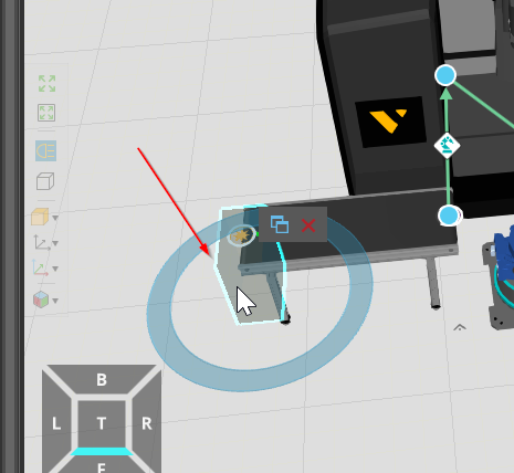
Open the ProductCreator’s Tab to see a list of settings related to part generation.
In this case, you can set the interval between part creation by adjusting the Interval item.
Result
Done!
