This article introduces the SPT Framework. First, the basic concept of SPT FrameWork, Function Block, and Interface will be explained, and next, Simulation mode and EtherCAT IO will be implemented using the Function Block of FB_DigitalSensor.
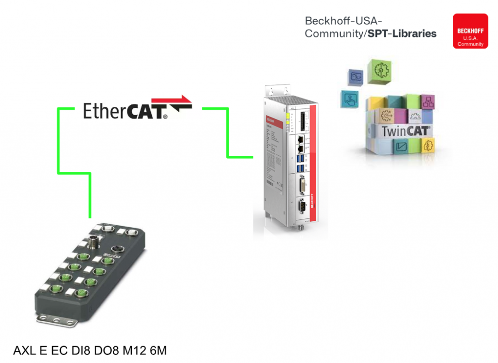
The EtherCAT IO is AXL E EC DI8 DO8 M12 6P from Phoenix Contact.
Let’s get started!
Video
Here is my Video Tutorial introduction and live code for the SPT Framework.
SPT Application Framework?
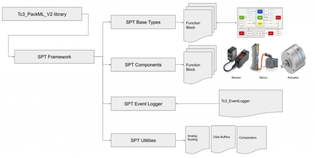
The SPT Application Framework is a collection of libraries and patterns for standardizing machine control software and is maintained and managed by Beckhoff USA.
Libraries
The SPT Framework uses the PackML library to allow the management of defined states for creating control programs. An important element in control design is to give the right commands at the right time so that they work with the rest of the machine.
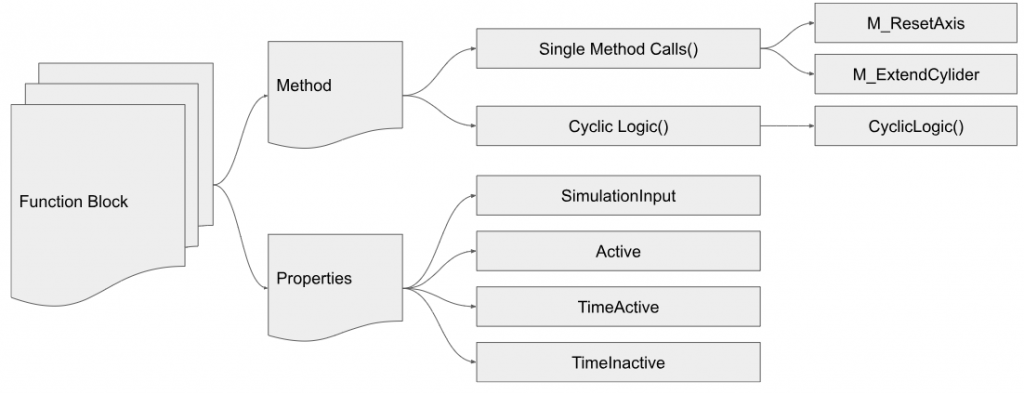
Cyclic Logic vs Single Method Calls
The SPT Framework uses Methods to invoke and execute specific controls, such as M_ExtendCylider and M_ResetAxis. These Methods can be called only once or multiple times, depending on the case. (For example, until the Method is successfully executed.)
In addition, the SPT Framework can use Methods to invoke commands during certain states. For example, a Resetting Method can be called to reset a Module to reset its state at the required time.
The SPT Framework can also use Cyclic method calls to monitor the Module state and switch to other states, such as Alarm or Fault, when they change.
SPT Base Types
Most Function Blocks in the SPT Framework Library inherit from FB_CyclicFB and implement I_CyclicFB, thereby using a common pattern for initialization and calling.
FB_CyclicFB allows access to the Local variable _InitComplete via the InitComplete Properties to check the initialization status of the corresponding Function Block.
This allows the Function Block to ensure that all necessary initialization steps have been performed. (For example, to verify that a pointer has been initialized before referencing it.)

Interface
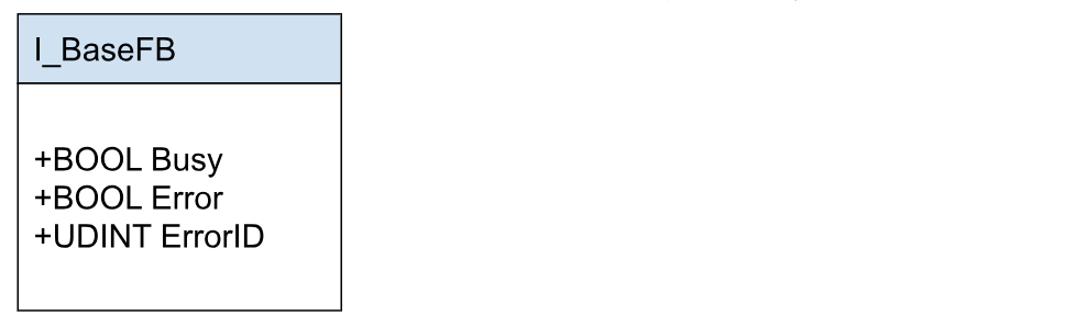
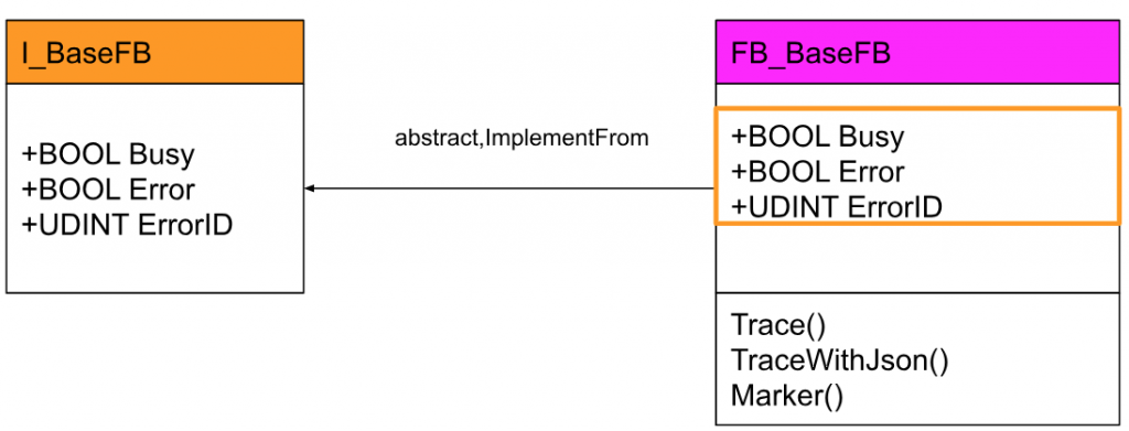
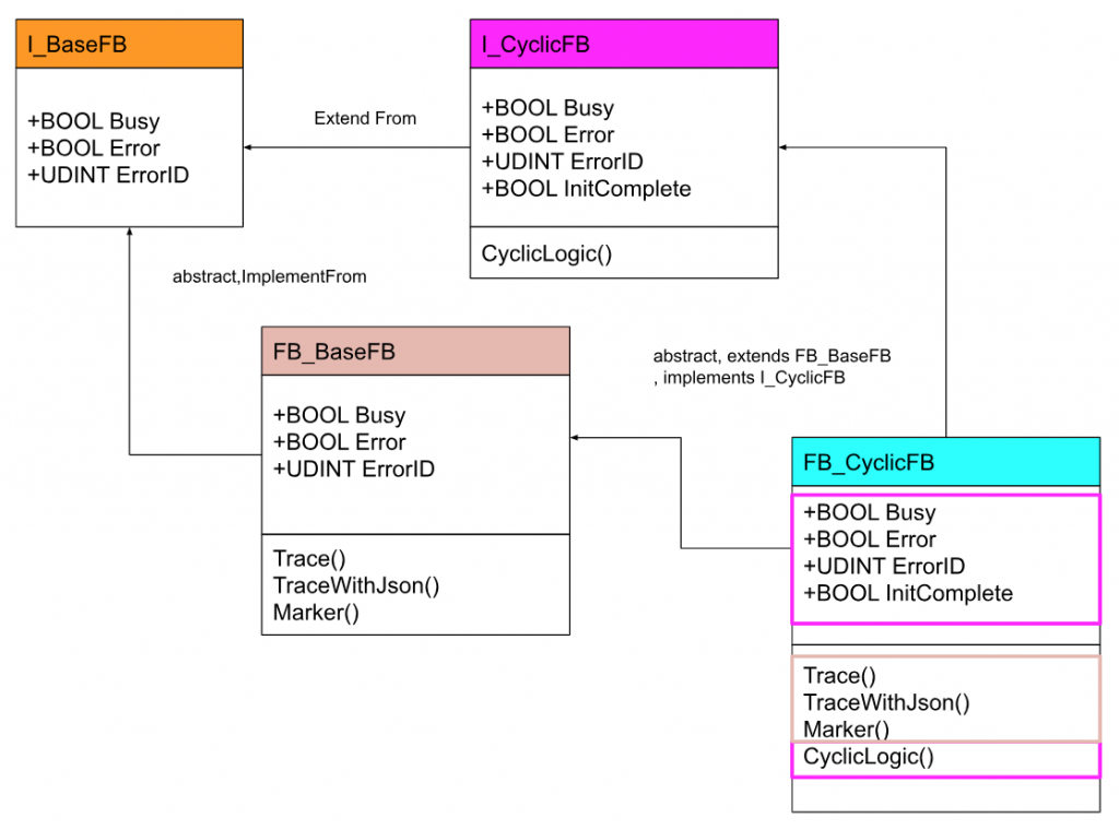
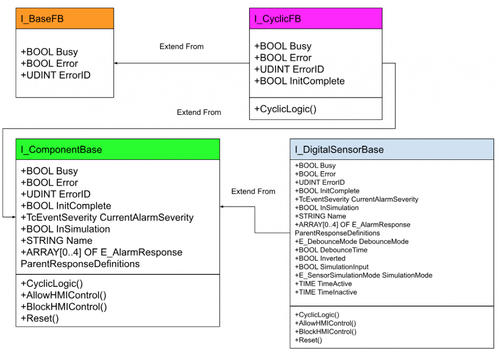
I_BaseFB
Defines the most basic functions of the Function Block used in the SPT Framework.
Properties
| Property | Type | Read/Write | Description |
| Busy | BOOL | R | 1=Function Block is executing Task |
| Error | BOOL | R | 1=Function Block has error |
| ErrorID | UDINT | R | error information |
I_CyclicFB
This Interface was extended from I_BaseFB. I_CyclicFB is defined in addition to I_BaseFB to call CyclicLogic() in a cycle with an additional Method.
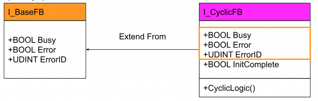
Properties
| Property | Type | Read/Write | Description |
| InitComplete | BOOL | R | 1=Function Block is available |
Methods
| Method | Type | Return | Description |
| CyclicLogic | BOOL | null | Execute the control program in cycles. |
Function Block
FB_BaseFB
This is the abstract Function Block, implemented from I_BaseFB; FB_BaseFB is the most basic building block of SPT Framework functions, including all I_BaseFB Properties.
FB_CyclicFB
(abstract, extends FB_BaseFB, implements I_CyclicFB)
FB_CyclicFB contains all I_CyclicFB properties and uses CyclicLogic() to execute cyclic logic.
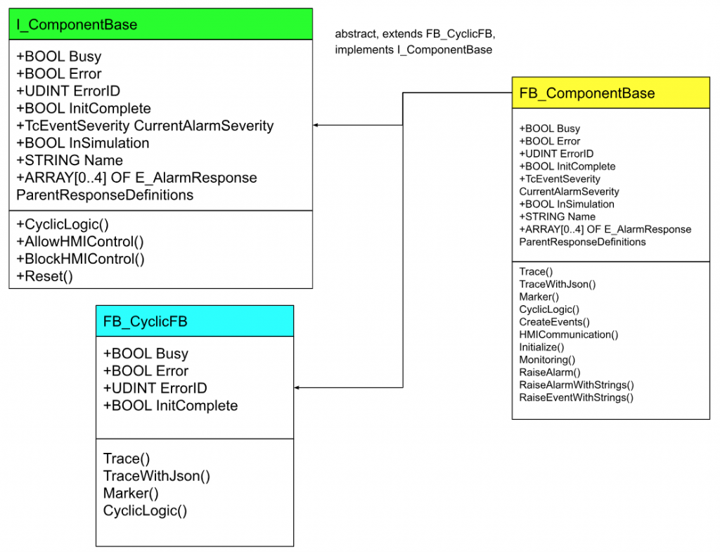
SPT Components
This is a Function Block that implements I_ComponentBase.
Interface
I_ComponentBase
This Interface defines the basic functionality required for SPT Components.
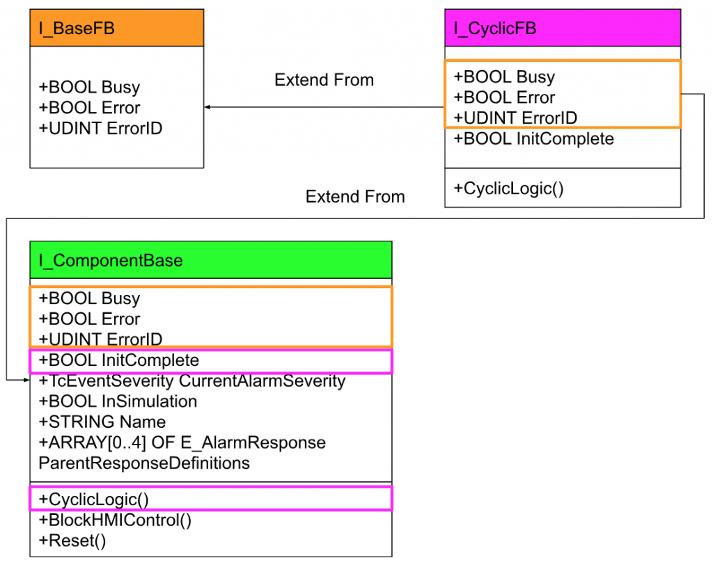
Properties
| Property | Type | Read/Write | Description |
| CurrentAlarmSeverity | TcEventSeverity | R | Returns the currently active event with the highest severity. |
| InSimulation | BOOL | RW | True=The corresponding part is in Simulation. |
| Name | STRING | RW | Component Name |
| ParentResponseDefinitions | ARRAY[0..4] OF E_AlarmResponse | RW |
Methods
| Method | Type | Return | Description |
| AllowHMIControl | BOOL | null | Part allows external functions via HMI |
| BlockHMIControl | BOOL | null | Component blocks external functionality via HMI |
| Reset | BOOL | null | Reset component errors |
I_DigitalSensorBase
This will be an Interface that defines the functionality of the digital sensor in SPT FrameWork.
Function Block
FB_ComponentBase
(abstract, extends FB_CyclicFB, implements I_ComponentBase)
All PROTECTED methods must be called using SUPER^.Method() in a Function Block with aligned I_ComponentBase and FB_CycliceFB functionality.
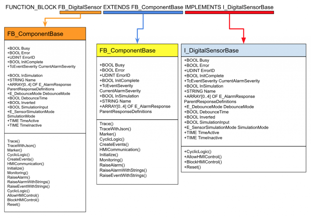
FB_DigitalSensor
FUNCTION_BLOCK FB_DigitalSensor EXTENDS FB_ComponentBase IMPLEMENTS I_DigitalSensorBase
This is a basic Function Block for digital signals and includes a locally defined HardwareInput AT %I*: BOOL for linking to hardware.
Download Library
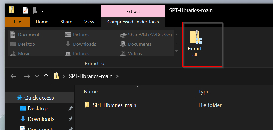
You can download Beckhoff USA’s SPT library from Github below.
https://github.com/Beckhoff-USA-Community/SPT-Libraries
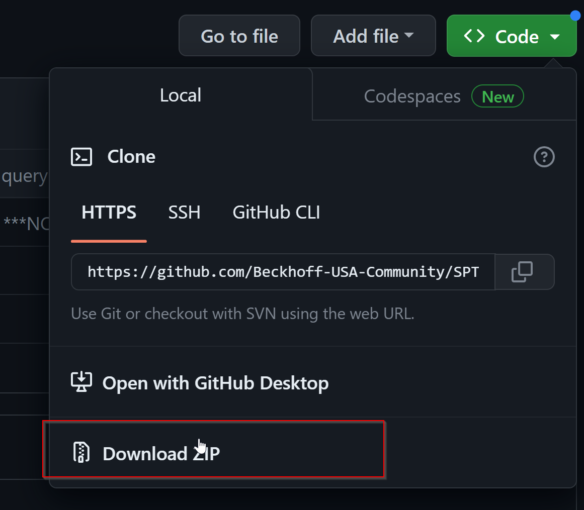
Unzip the downloaded ZIP file.
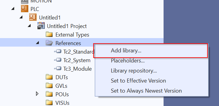
Add Library
To add the SPT library, go to References>Add Library.
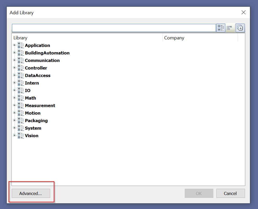
Click the Advanced button.
Click the Library Repository.. button.
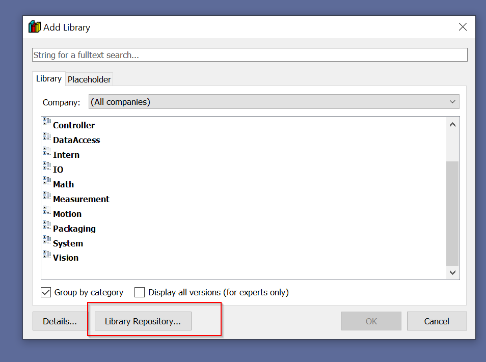
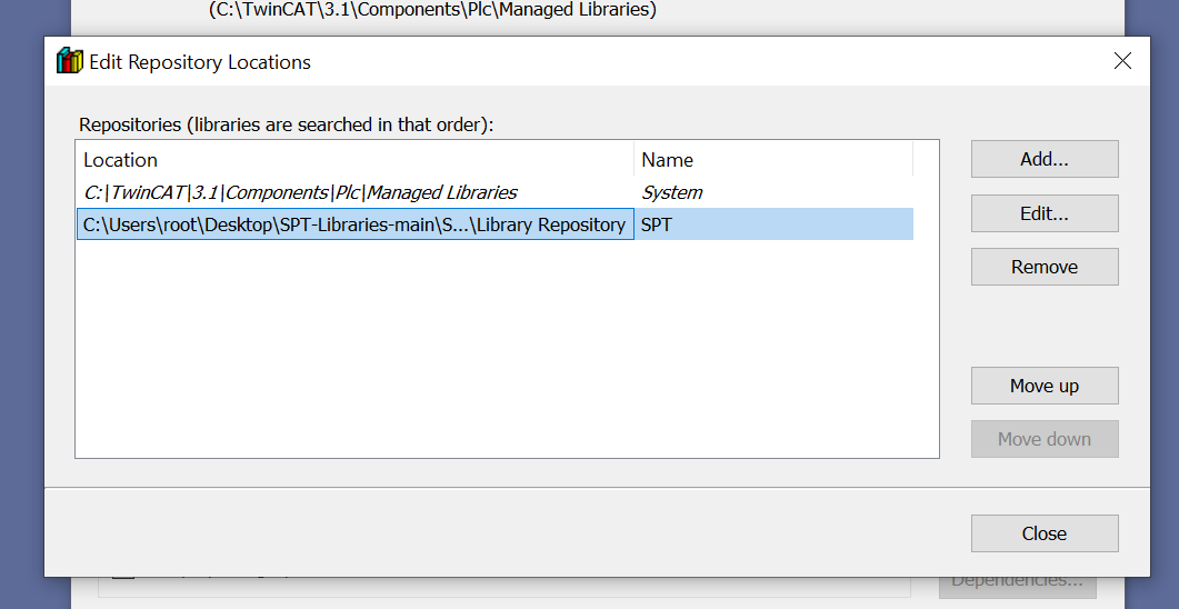
The Library Respository settings screen is now displayed.
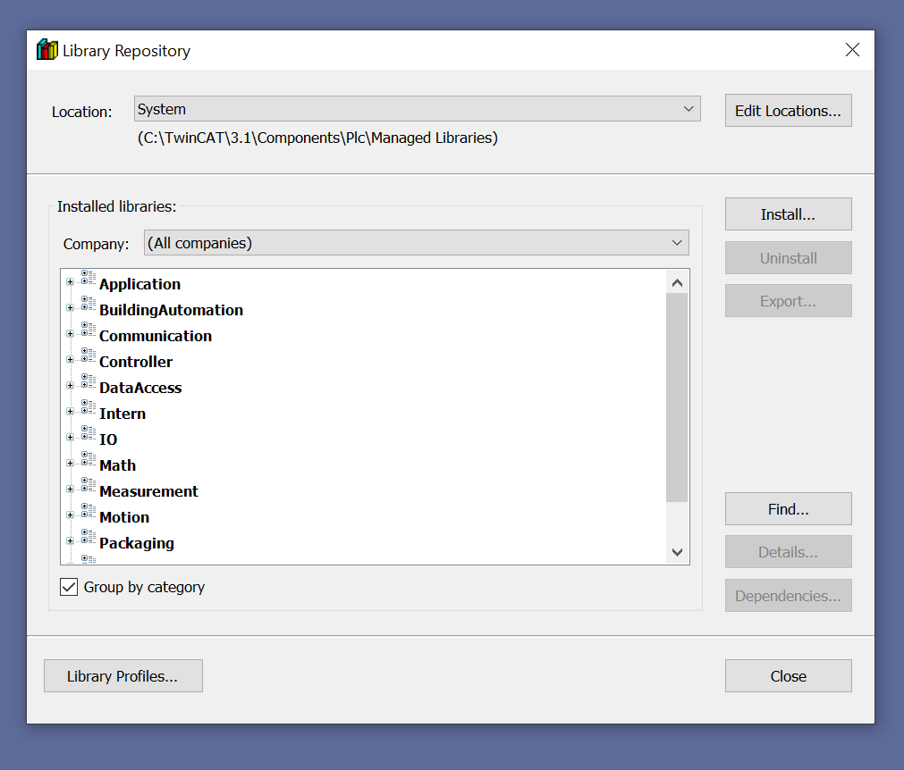
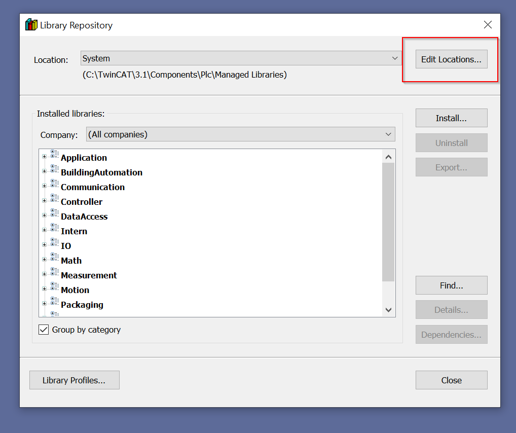
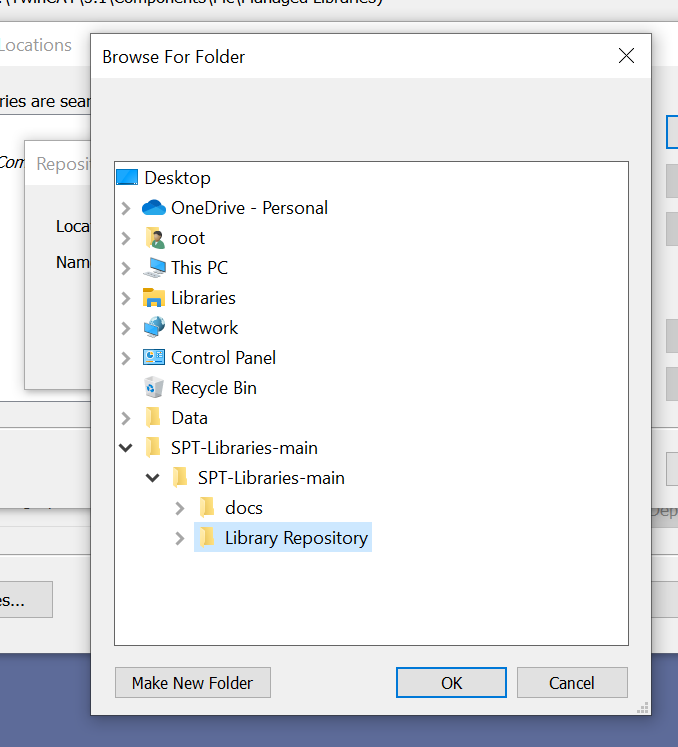
Click Edit Locations to add the location where the Library is to be stored.
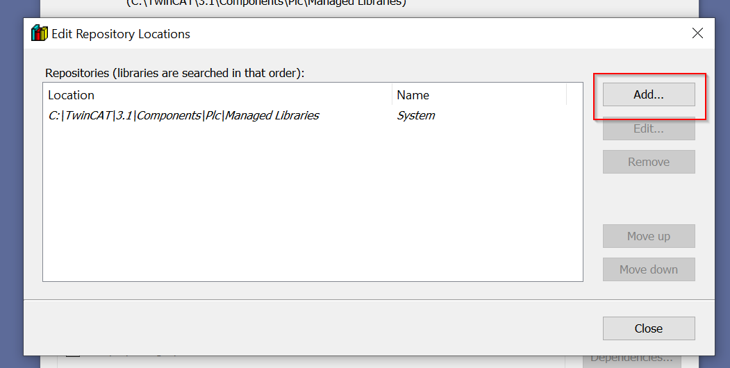
Add to add a new library.
Click on … button.
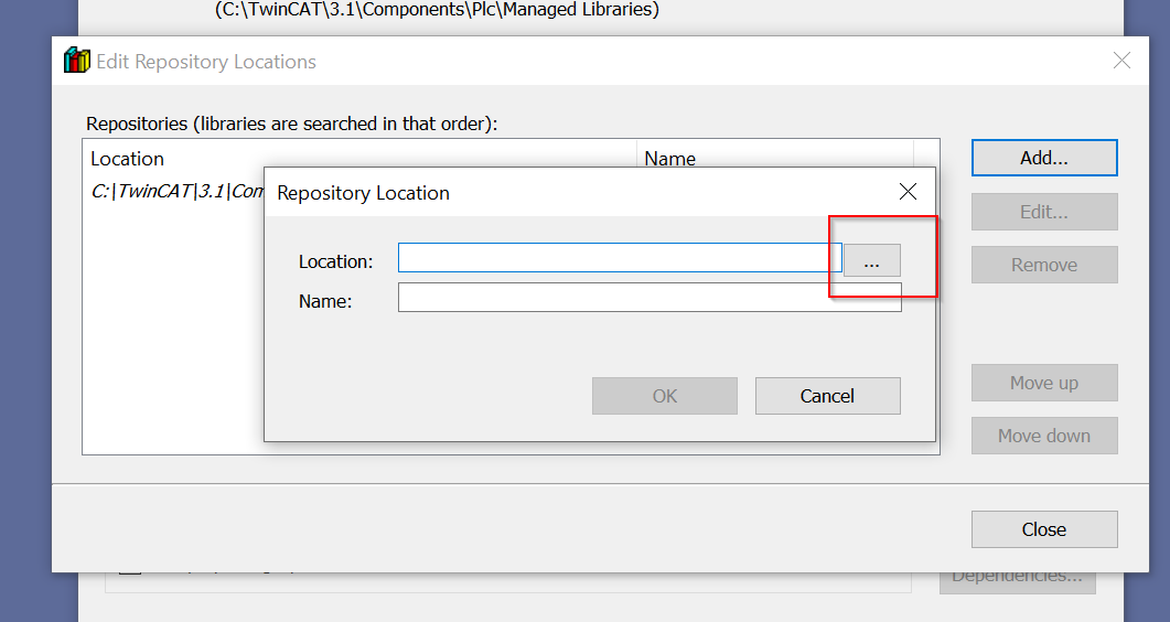
Specify SPT-Libraries-main>Library Repository for the library just downloaded from Github.
Name does not need to be specified, but we will use SPT for easy understanding.

Done!
You will see a library created by Beckhoff Automation LLC (i.e., Beckhoff USA) in Company.
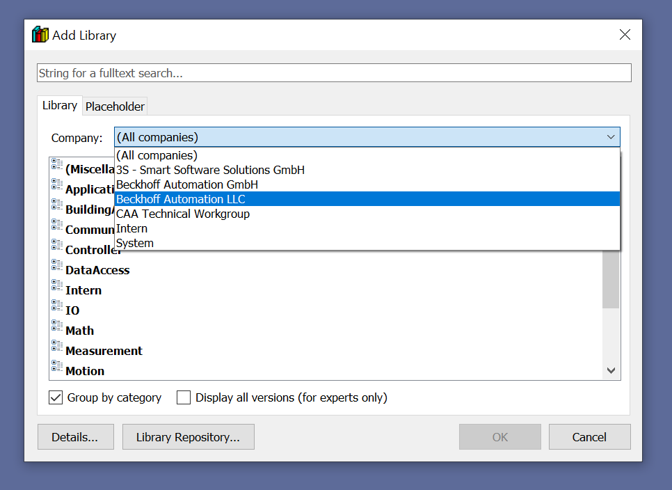
Inside you will find libraries such as SPT Drivers.

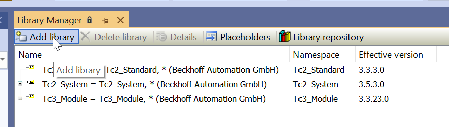
Now all that is left is to add the SPT library to the project using Add Library.
Program
Here is an example program using FB_DigitalSensor.
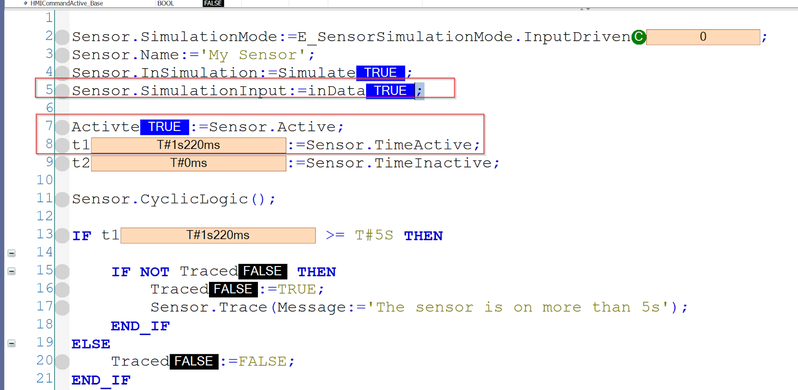
| PROGRAM MAIN VAR Sensor :FB_DigitalSensor; Simulate :BOOL; Activte :BOOL; t1,t2 :TIME; Traced :BOOL; inData :BOOL; END_VAR Sensor.SimulationMode:=E_SensorSimulationMode.InputDriven; Sensor.Name:=’My Sensor’; Sensor.InSimulation:=Simulate; Sensor.SimulationInput:=inData; Activte:=Sensor.Active; t1:=Sensor.TimeActive; t2:=Sensor.TimeInactive; Sensor.CyclicLogic(); IF t1 >= T#5S THEN IF NOT Traced THEN Traced:=TRUE; Sensor.Trace(Message:=’The sensor is on more than 5s’); END_IF ELSE Traced:=FALSE; END_IF |
Result
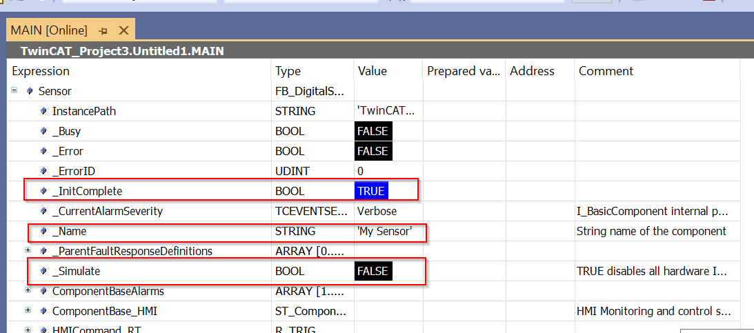
Expand the Instance called Sensor and check the status of the FB.
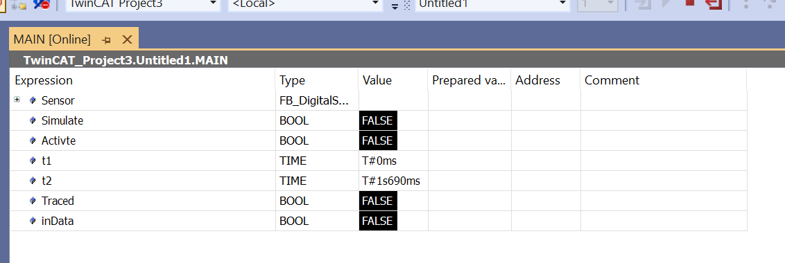
_InitComplete is True, indicating successful initialization.
_Name indicates the device name set in the program.
_Simulate is False, indicating that simulation mode is Off.
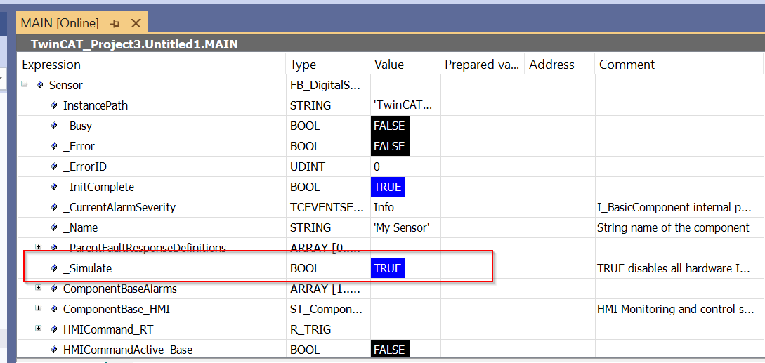
Start the simulation mode by setting Sensor.InSimulation to True.

_Simulate is now True and FB is in simulation mode.
SimulationInput is set to True then Sensor.Active is set to True.
Active becomes True, indicating that the sensor is now turned on.

Connect with EtherCAT IO
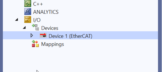
Next we connect to the actual EtherCAT IO and add an EtherCAT Master at I/O>Deviecs>Add New Item.
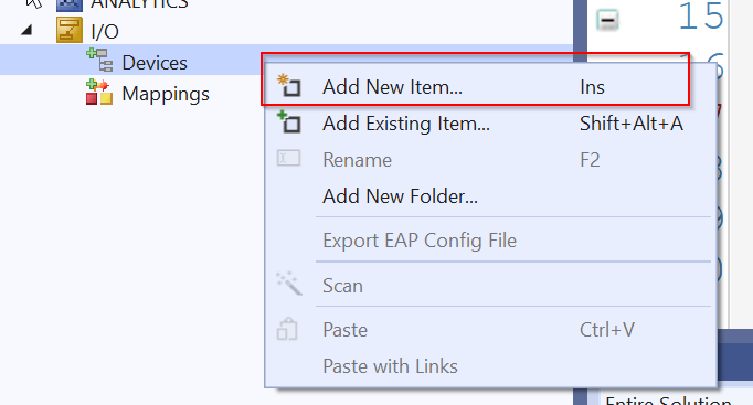
Done!EtherCAT Master has been added.
Configure Network Adapter in Search.

Configure the Network Adapter to be used as the EtherCAT Network.
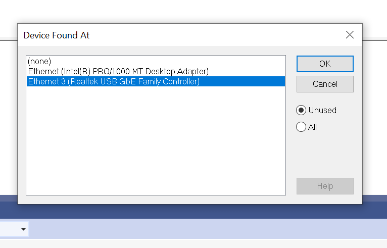
Done!

Add New Slave
Add a new EtherCAT Slave by right-clicking on EtherCAT Master>Add New Item.

Select AXL E EC DI8 DO8 M12 6P for this use and add with Ok.
Done!

Link Variables
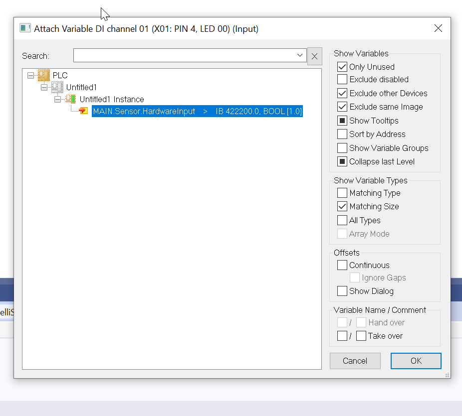
Right-click on the channel connected to the sensor > Change Link.
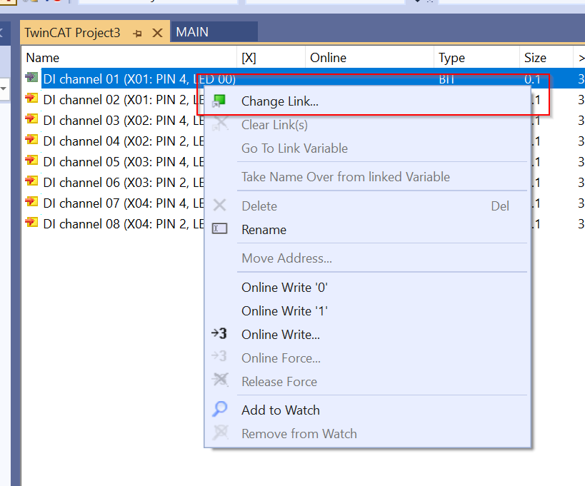
HardwareInput is a ProcessIO variable for FB_DigitalSensor.
Result
You can check the operation in this Youtube video.
Download Sample Project
You can download a sample project from Github.
https://github.com/soup01Threes/TwinCAT3/blob/main/TwinCAT%20_SPTFrameWork_Example01.tnzip
コメント
Thanks you very much for all the details and great work that has been put in, to write this article.
I am also curious on how to use various other properties in real life project like
Properties like
Busy
Error,
Trace,
[0..4]AlarmResponse. // I am also not sure why we have array of 4 and who sets the value of these properties.