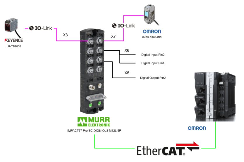
This article provides guidelines for connecting an Omron NX1 CPU to a Murrelektronik EtherCAT IO-LINK, although the only IO-LINK device is the Keyence LR-TB2000/OMRON E3AS-HL500MN, I will explain the some detailed parameters in the Murreletronik IO-Link Master such as individual settings for Pin 2 and Pin 4.
Let’s start!
Reference Link
Thanks!
This article was made possible thanks to equipment provided by Murrelektronik Turkey. Thank you very much.
Murrelektronik is a global company in the development, manufacturing and sales of automation solutions, divided into four core areas: power and control, interfaces, cables/connectors and IO systems. Murrelektronik is always offering high quality and innovative products to better serve our customers’ applications.

Office
Murrelektronik San. ve Tic Ltd Şti
Perpa Ticaret Merkezi A Blok Kat 11 No.1403
34384 Okmeydani/Istanbul/TR
Telephone
+90 212 2222298
E-Posta: info@murrelektronik.com.tr
Implementation
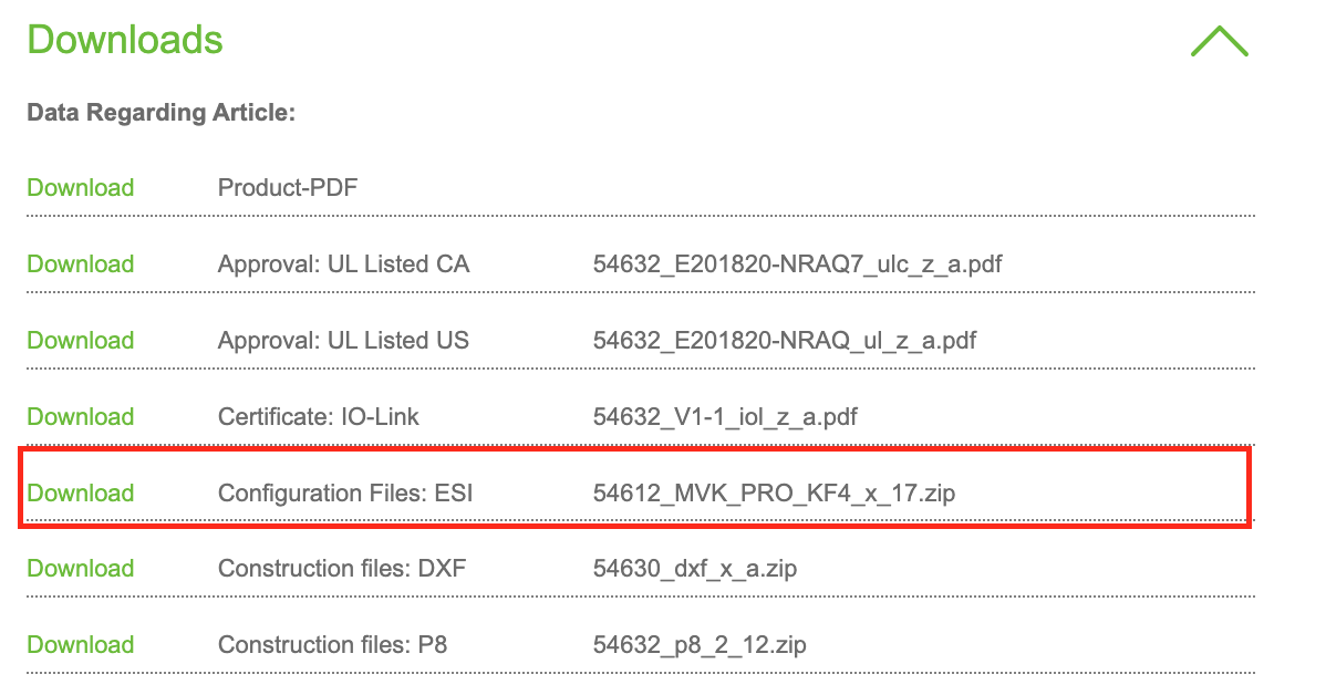
Download ESI File
Download the ESI File for IMPACT67 Pro EC DIO8 IOL8 M12L 5P from the link below.
Omron Side
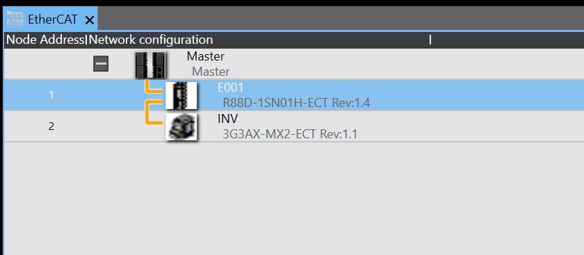
EtherCAT
Open EtherCAT to set up the EtherCAT network.
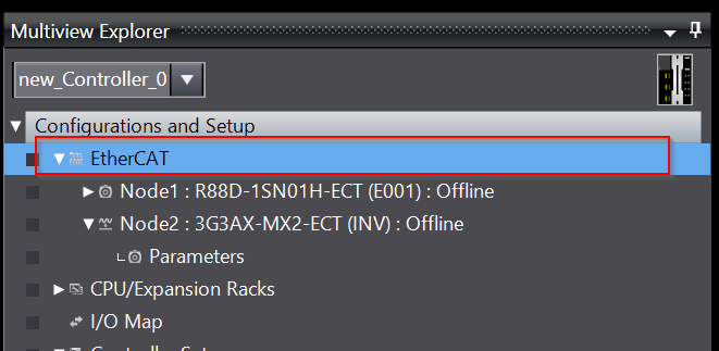
The EtherCAT network construction screen appears.
Install ESI
To install the ESI File into Sysmac Studio, click Master>right click>Display ESI Library.

You will see a list of libraries installed in Sysmac Studio, and add a new ESI File with Install(File).
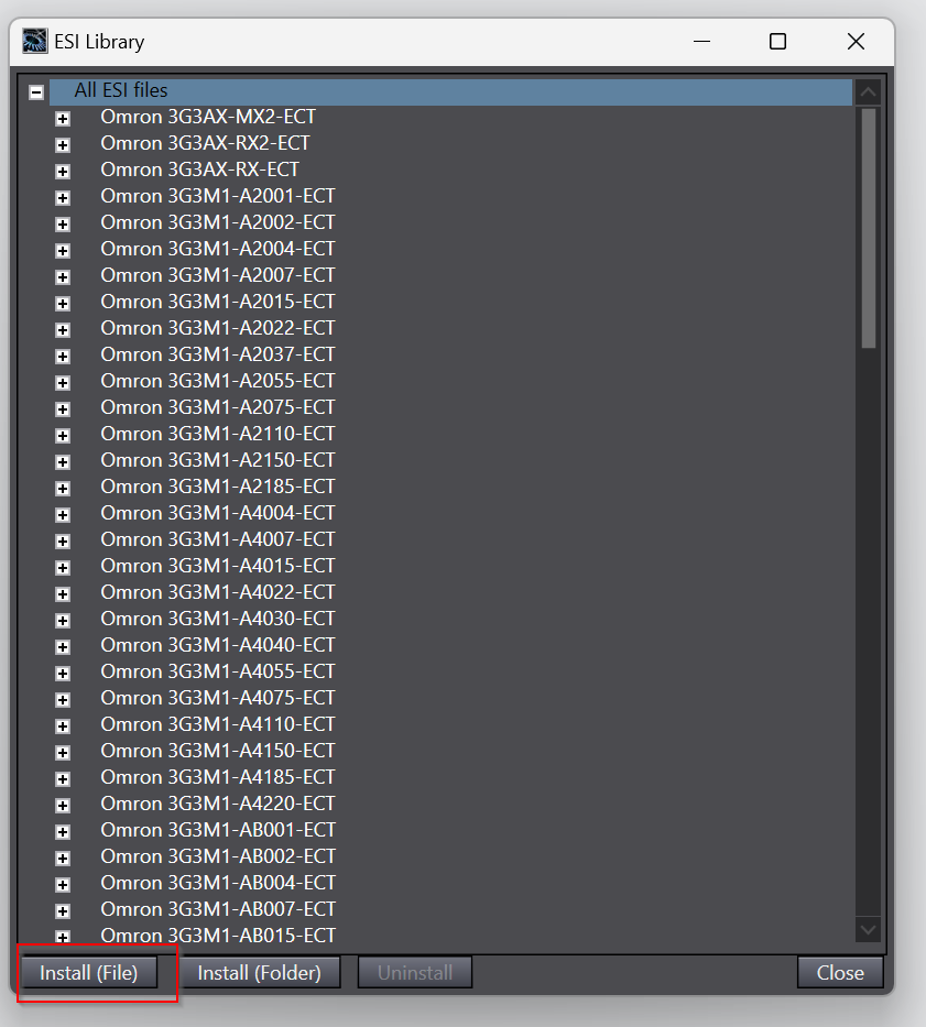
Open the ESI File that you have just downloaded from Murreletronik’s website.

Proceed with Yes.

Done!

Murreletronik products are now displayed in the Toolbox on the right side of Sysmac Studio.

Add Murreletronik Devices
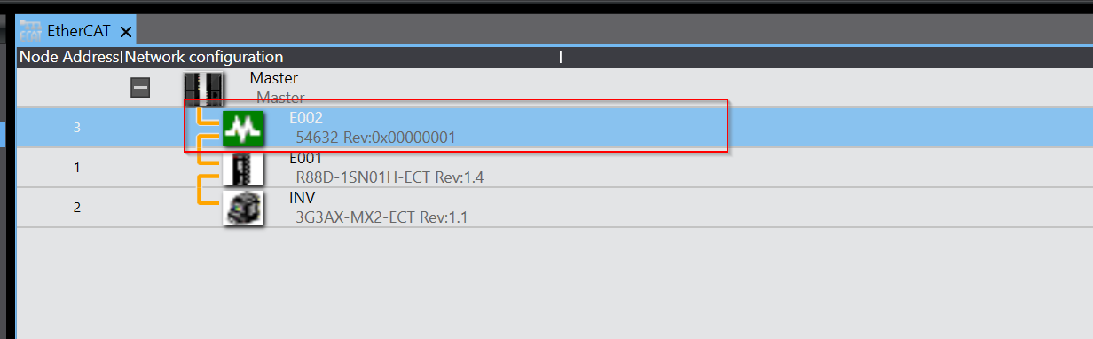
To add Murreletronik’s IOLINK Master to your EtherCAT network, right click > Insert.

Done!Murreletronik’s EtherCAT IO-LINK Master has been added.
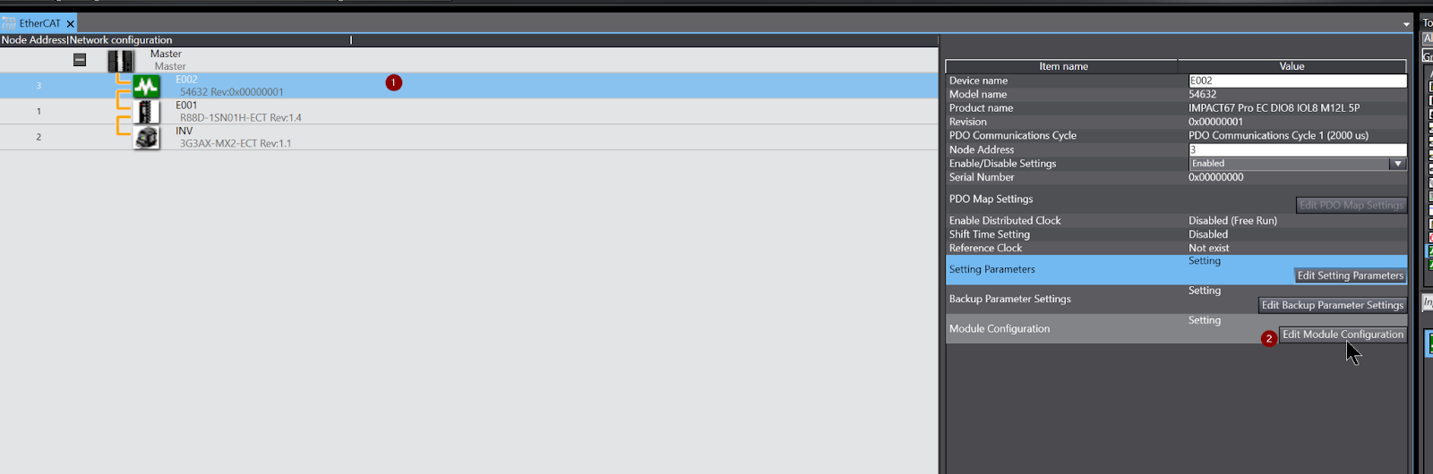
Module Configuration
Next, to change Murreletronik’s Port settings>Please select the Murreletronik device>click on Edit Module Configuration.
It turns to the Port configuration screen and everything is disabled on Default.
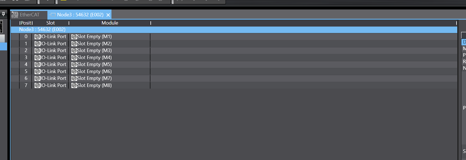
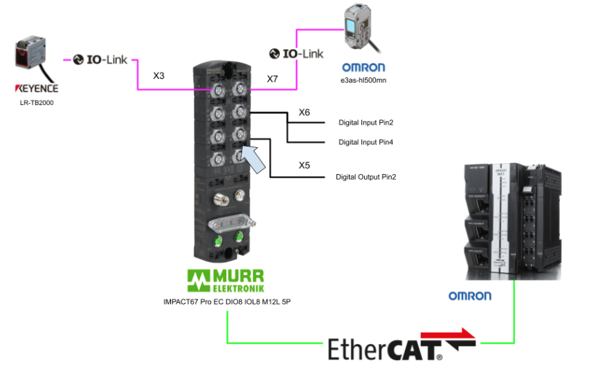
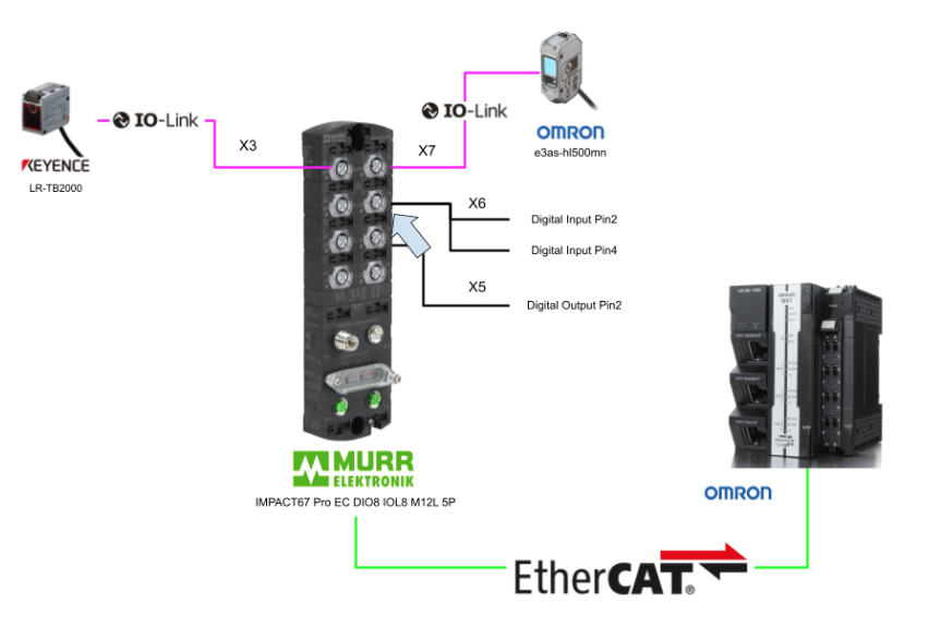
Port X3
Port X3 is connected to Keyence LR-TB2000.
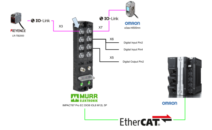
Port3 X3 is connected to the Keyence LRT2000, so drop the IOL_2/0_I/O Bytes from the right side to IO-Link Port X3.

Done!IO-Link Port X3 is now configured as an IO-Link Port with 2Bytes input occupied.
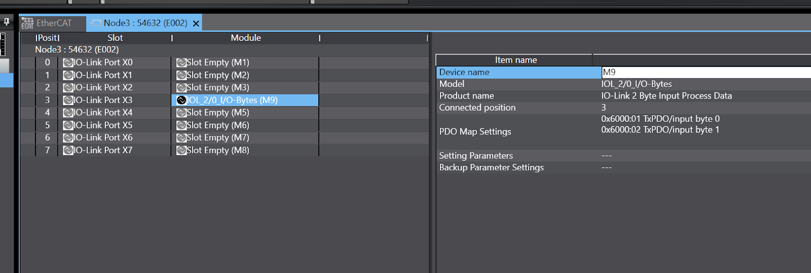
Please change the name from the Field of Device Name to a name that is easy to understand. The Device Name is related to the automatic variable generation in IO Mapping.

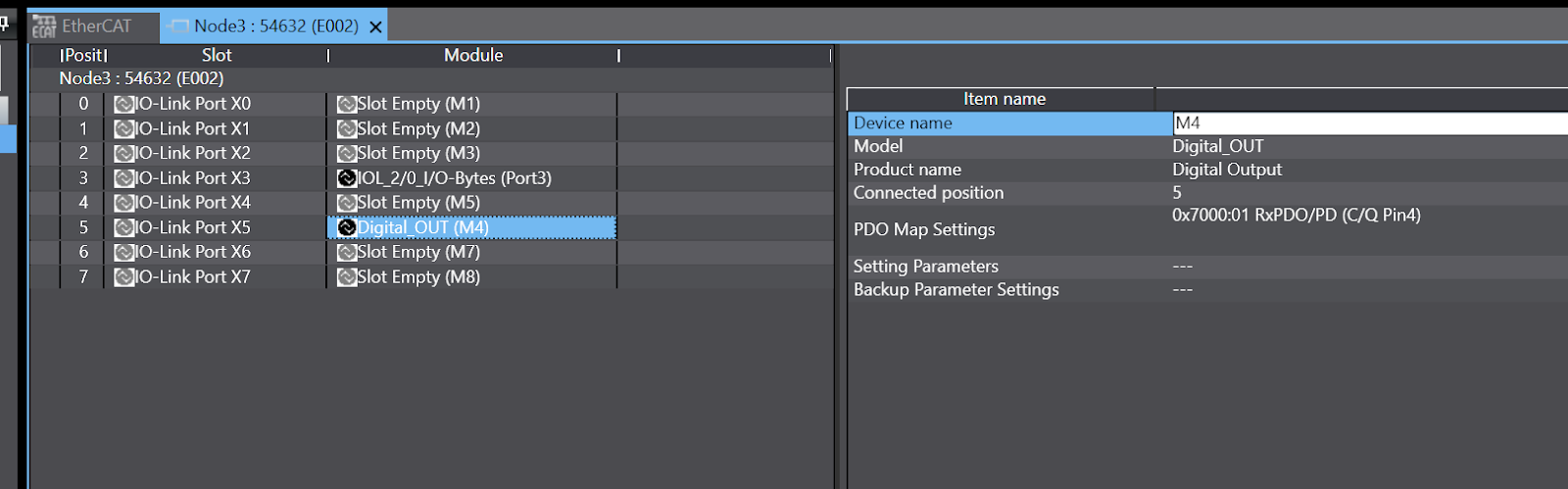
Port X5
Port X5 is connected to digital output Pin 2.
Port X5 is connected to the digital output, so drop the Digital Out from the Toolbox to IO-Link Port X5.
Done!IO-Link Port X5 is now configured as a digital output port.
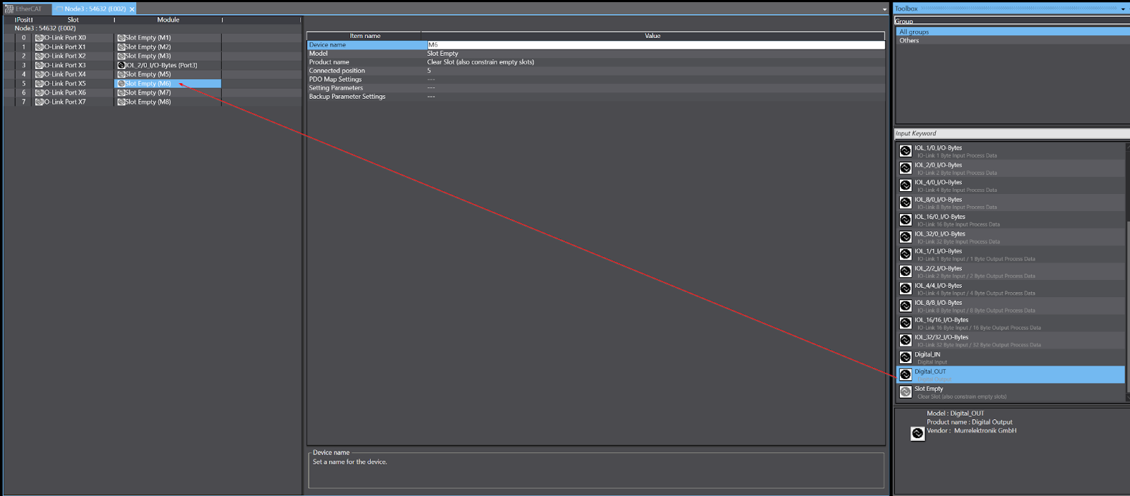
Port X6
Port X6 is connected to both Pin2 and Pin4 digital inputs.
Port X6 is connected to the digital input, so drop Digital Input from the Toolbox to IO-Link Port X6.
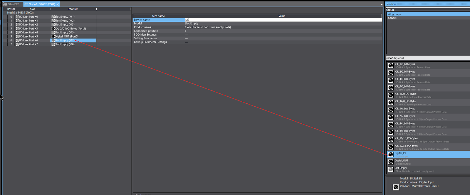
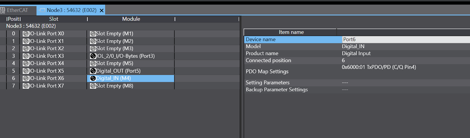
Done!IO-Link Port X6 is now configured as a digital input port.
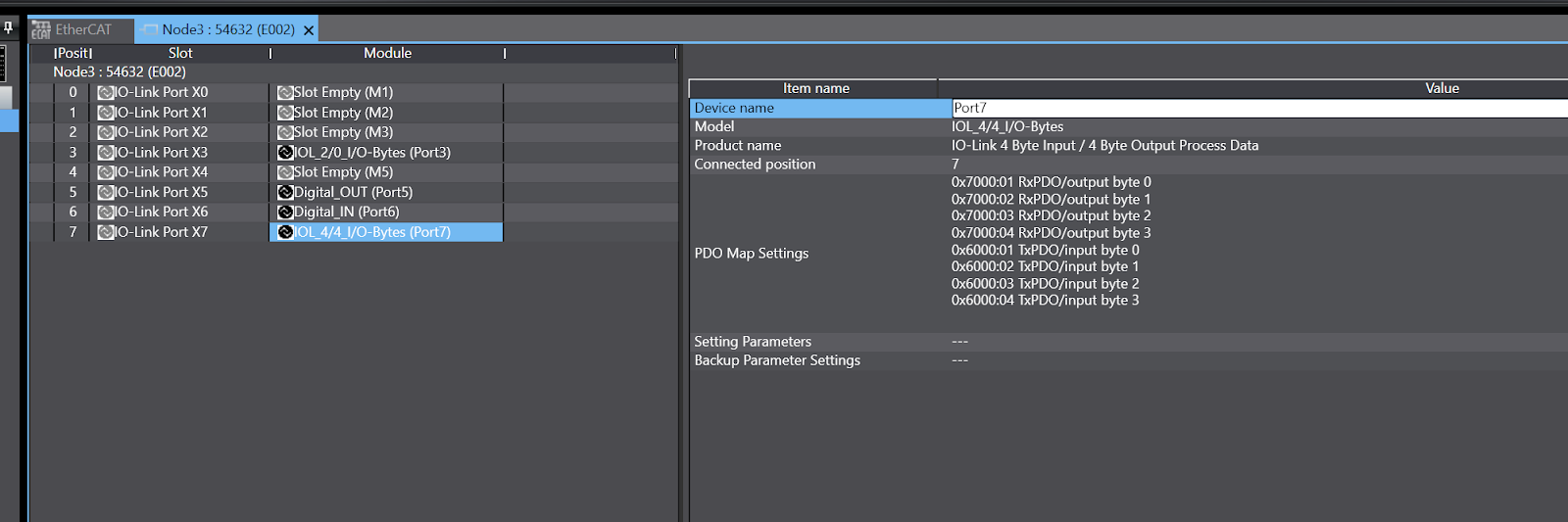
Port X7
Port X7 is connected to Omron’s IO Link device E3AD-HL500MN.
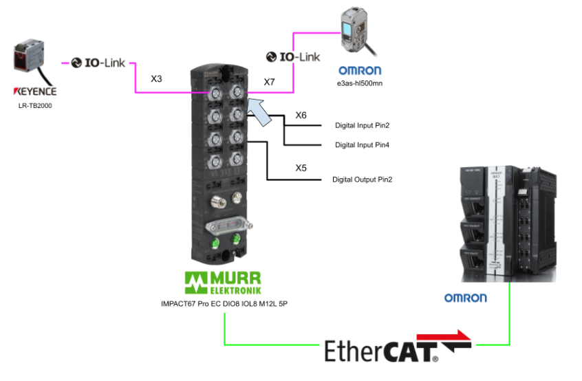
Port X7 is connected to OMRON’s E3AS-HL500LMN, so drop IOL_4/4_I/O-Bytes from Toolbox to IO-Link Port X7.

Done!IO-Link Port X7 is now configured as an IO-LINK Port occupying 4Bytes I/O.
Settings Parameters
The next step is to configure the Murreletronik main unit.Click on Setting Parameters>Editing Setting Parameters.

A list of Murreletronik main unit parameters is displayed.
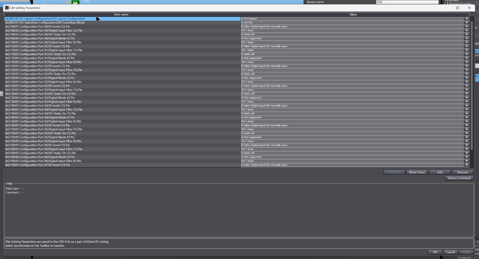
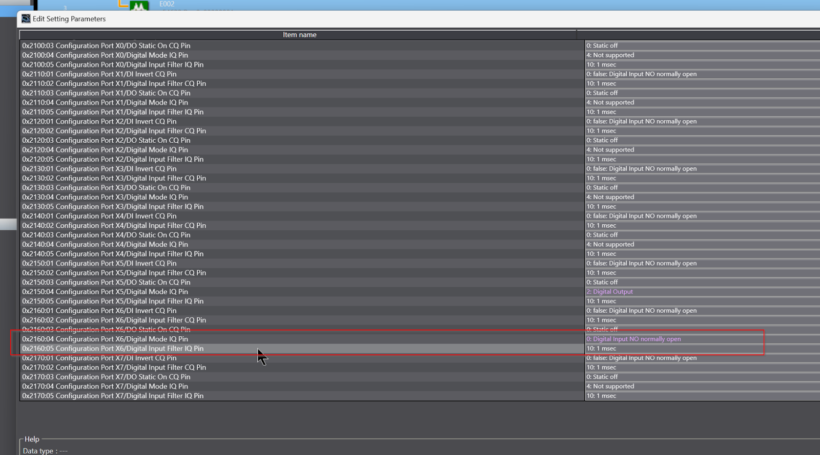
Port X5 Setting
Pin 2 of Port X5 is connected to the digital output, but Pin 2 is unused on Default. Therefore, set 0x2150:04 Configuration Port X5/Digital Mode IQ Pin as Digital Output. Then Pin2 becomes a digital output.

Port X6 Setting
Pin 2 of Port 6 is also connected to the digital input, but Pin 2 is not used by default, so set 0x2160:05 Configuration Port X6/Digital Mode IQ Pin as Digital Input NO Normal Open. Then, Pin2 will be used as a digital input. Then Pin 2 becomes a digital input.
I/O Mapping
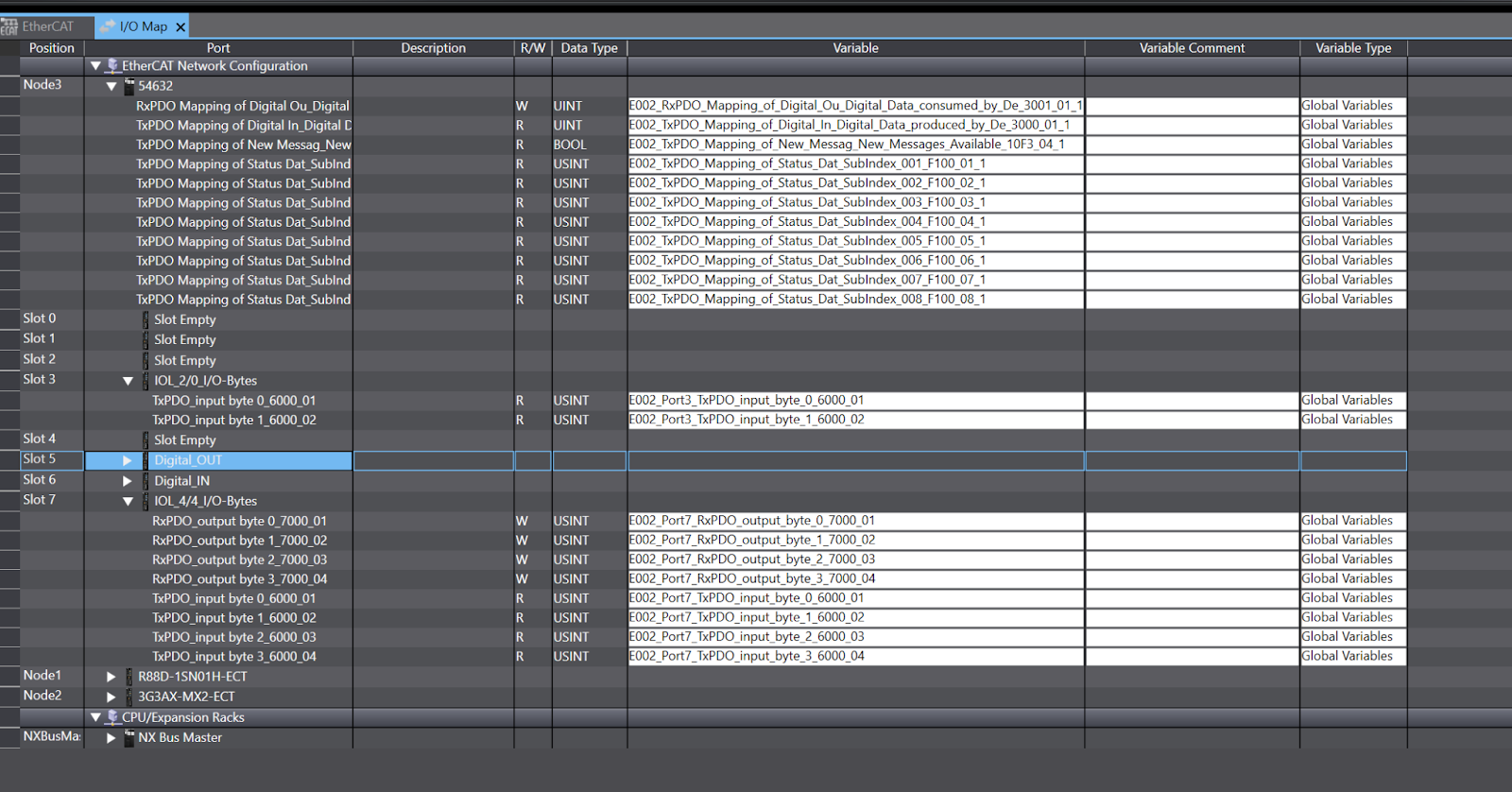
Now that the Hardware Configuration has been created, the next step is I/O Mapping.
This is the I/O Mapping screen in Sysmac Studio.
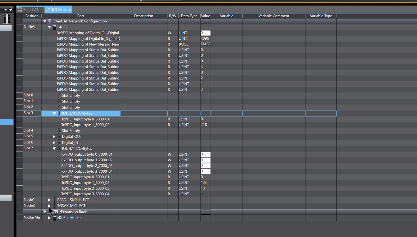
Expand EtherCAT Network Configuration>Node3 (Murreletronik EtherCAT IO-LINK Master used in this article), select all Process Data for RxPDO and TxPDO>right click>Create Device Variable with Prefix to create the variable.
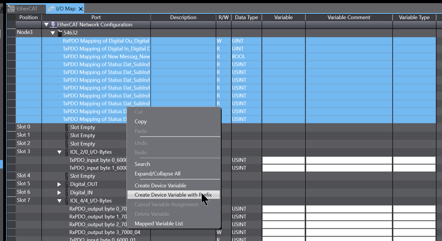
The Prefix function allows you to match the rules to some extent when creating variables. For example, in this case, if the Prefix is set to E002_, all variable names generated by Sysmac Studio will start with E002_.
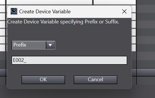
Done!Variables have been created.

Use the same operation to automatically create a variable for Process Data in the IOLINK Port.
Program
Now we can make the program – and for the omron tutorial, I will use Ladder.
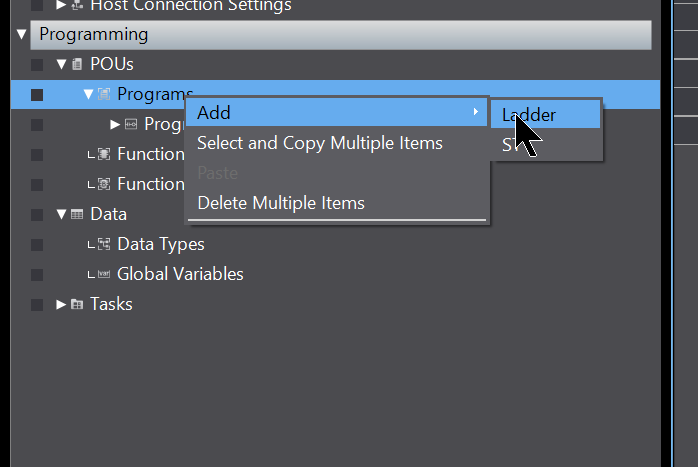
Add Program
Add a new ladder program at POUs>Programs>Add>Ladder.
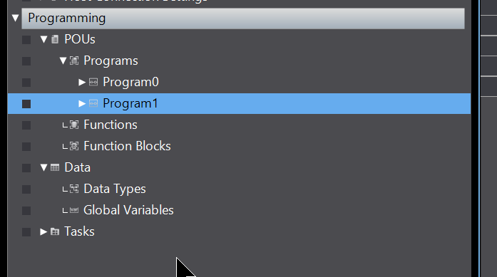
Done!New programs have been added.
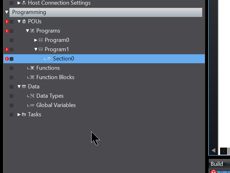
Sysmac Studio will automatically add Section0 as well.
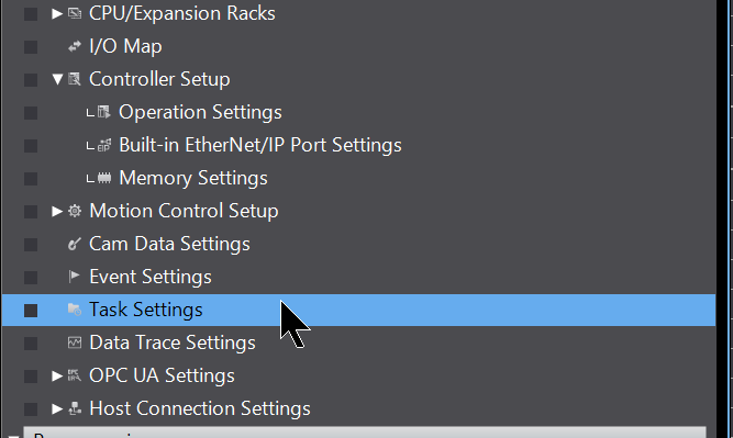
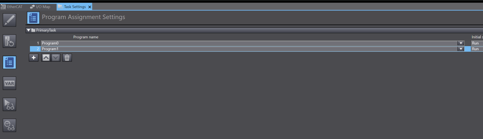
Task Setting
Now that you have added a new program, change Task Settings to allow this program cycle to run.
Click the + button from the Program Assignment Settings screen.

A new column will be added, and select Program1, which was newly created earlier.
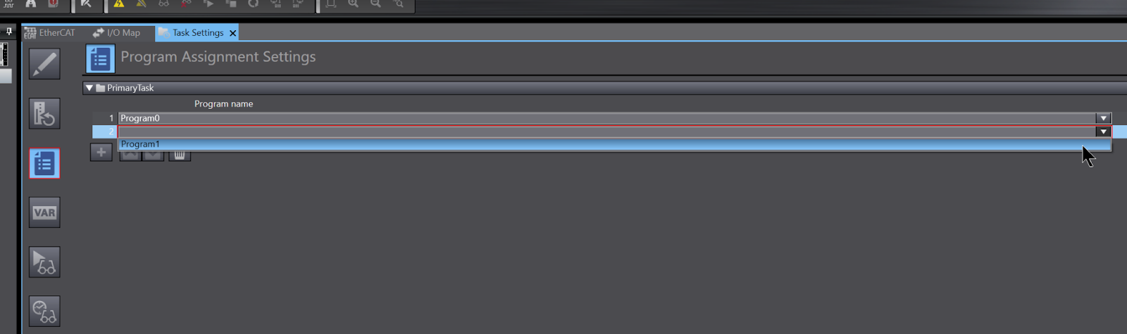
Done!
Data Type
The next step is to define the structure.
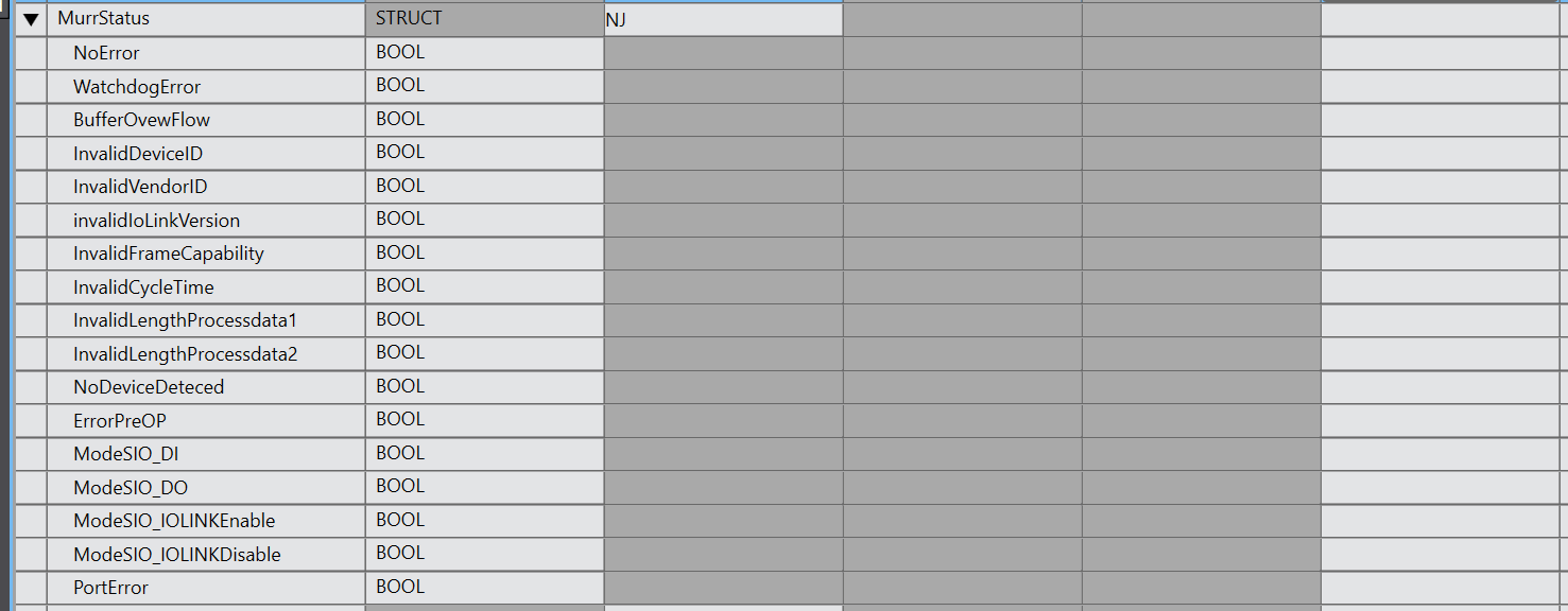
MurrStatus
This is a structure that summarizes the Port state of Murreletronik.
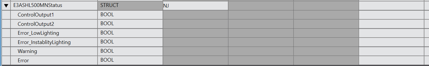
E3AS-HL500MNStatus
Here is a structure that summarizes information about Omron’s IO-Link Sensor E3A3-HL500MN.
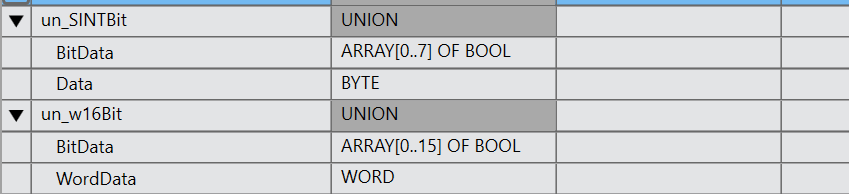
UNION
The next step is to define the UNION.
un_SINbit/un_w16Bit
To make the program a little easier here, we defined a Byte<–>Bool array UNION and a WORD<–>Bool array UNION.
Main
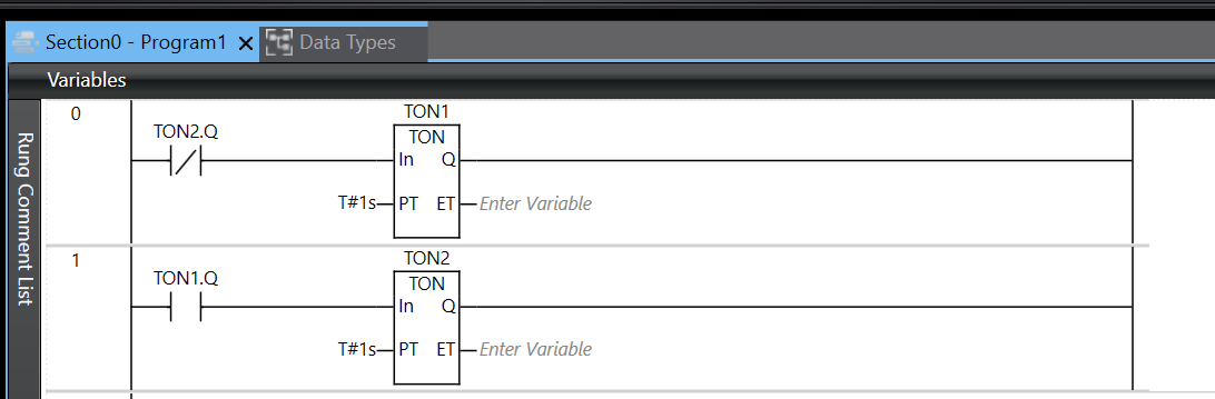
Rung0,1 1s Pulse TImer
Rung0,1 uses the IEC Timer to generate 1 second ON/OFF repetitions.
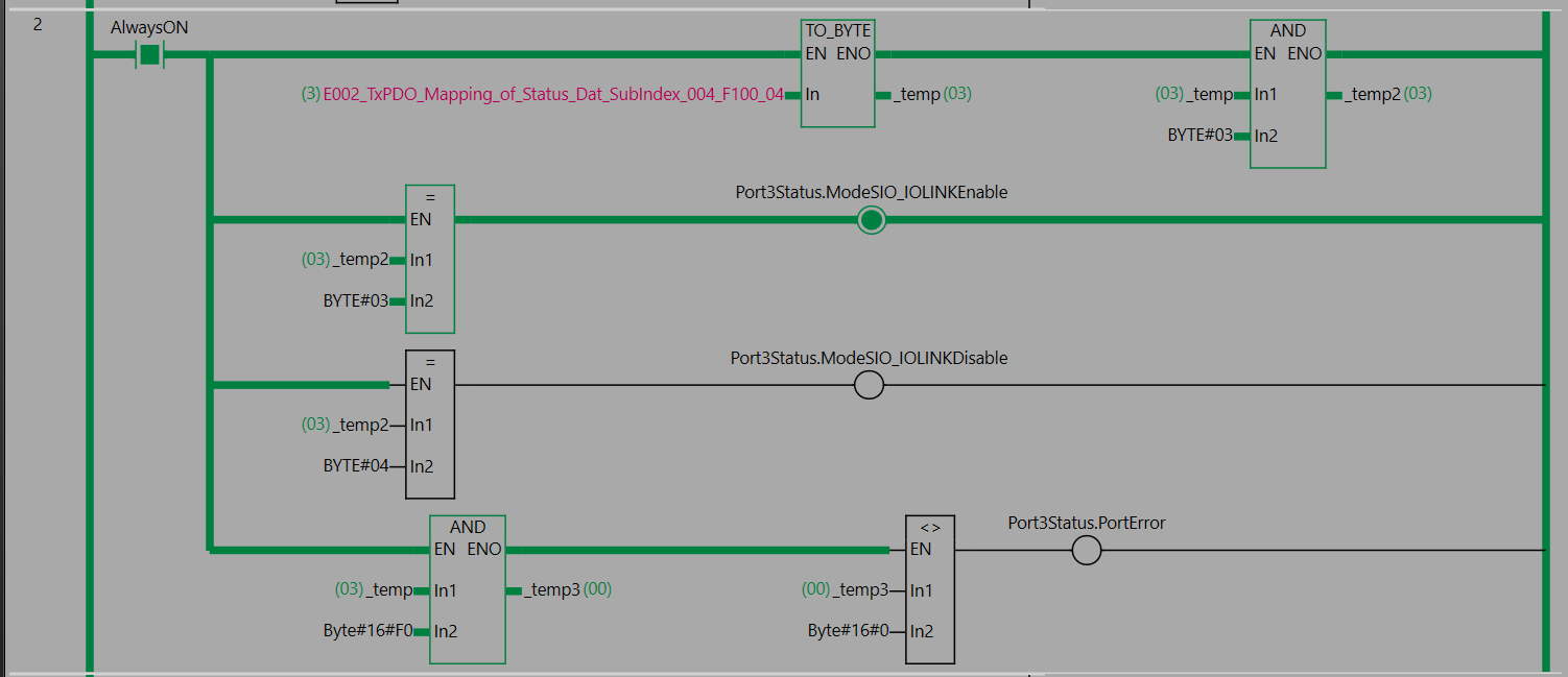
Rung2 Port3 Status
Rung2 determines whether the Port is in normal IOLINK communication status from the Port status data received by the Murrelektronik IO-LINK Master.

According to the Manual’s description, the n in State of IO-Link Port n indicates the location of the Module, and 0004=Port3 when the Sysmac Studio variable is generated.
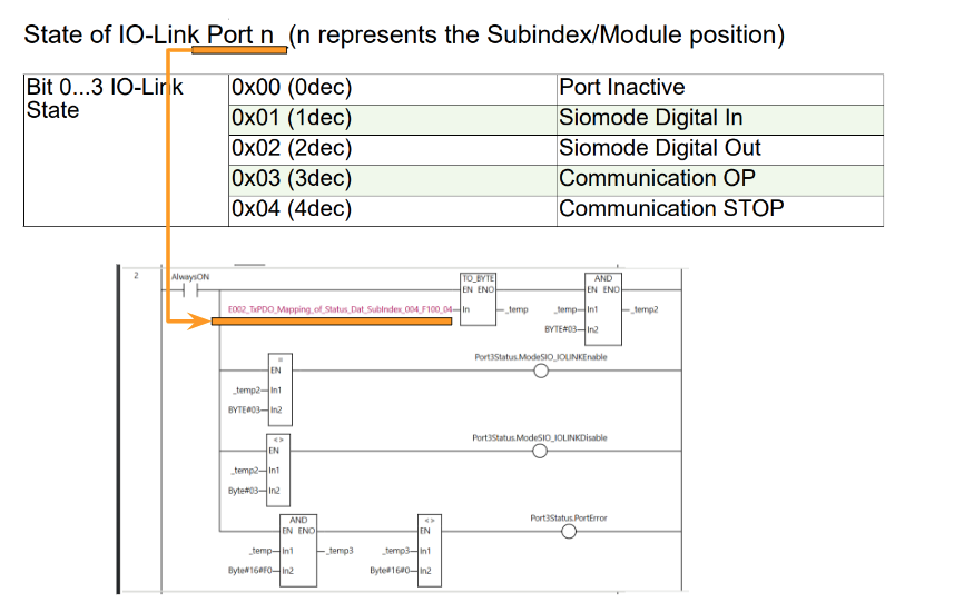
Therefore, E002_TxPDO_Mapping_Of_Status_Dat_Subindex_004_F100_04 is the diagnostic information of Port 3, and is converted from USINT to BYTE using the TO_BYTE function, and the current Port information is taken by BYTE#03 and AND function.
If the current IO-Link Port state is 0x03, it indicates that the Port and the IO-Link device are communicating without problems, so set ModeSIO_IOLINKEnable to True.
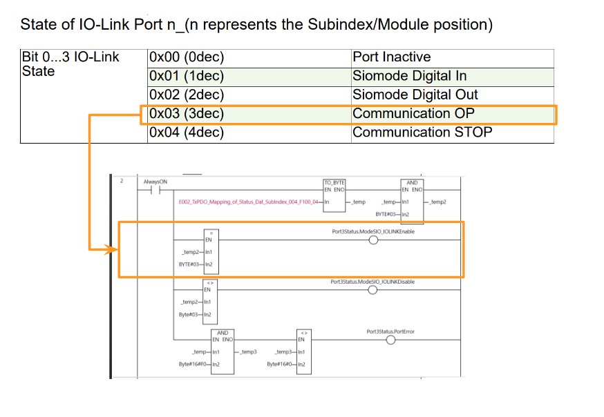
Otherwise, you know that the IO Link communication state of the Port is either an error or not set as IOLINK.
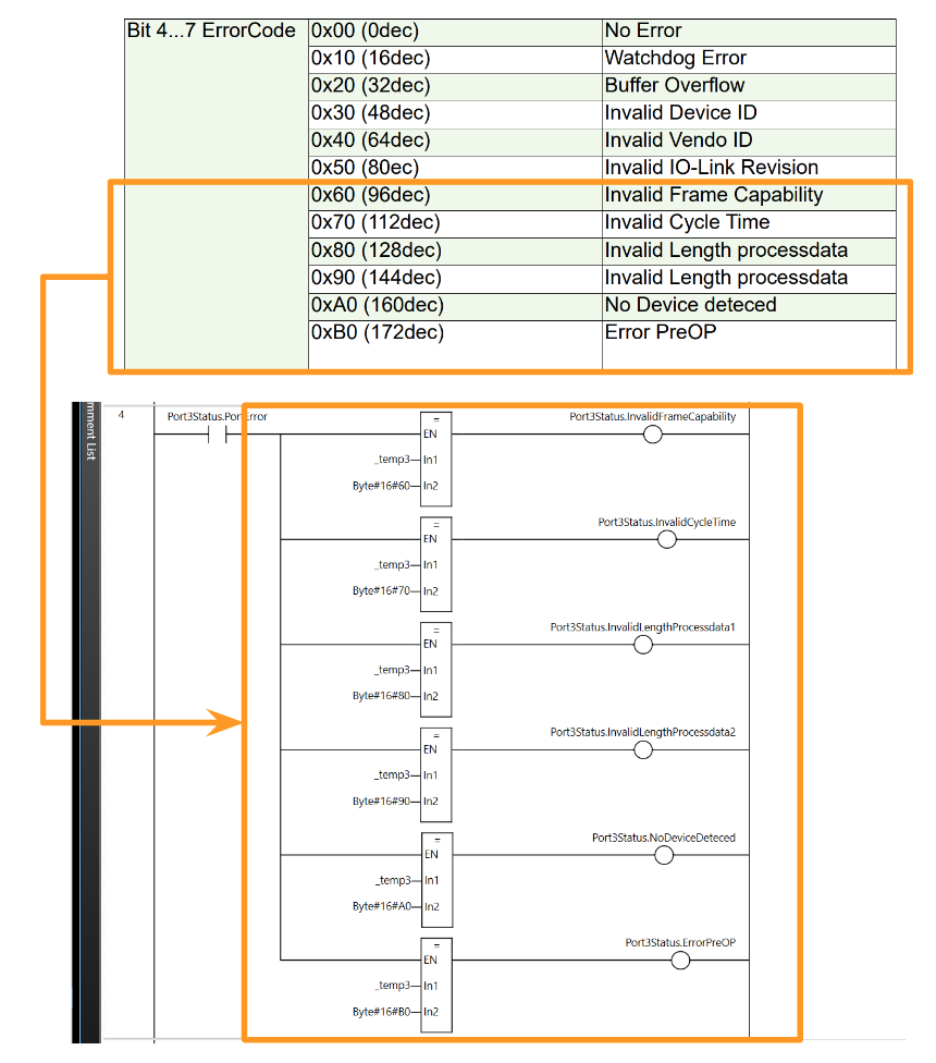
According to the manual, Bits 4 through 7 are error codes for the corresponding Port. Therefore, if the AND function and 16#F0 are used and the value is not 0, the Port error is indicated.
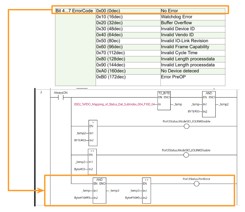
Rung3 Error Code‐1
Rung3 makes the appropriate variable True/False depending on the error code.
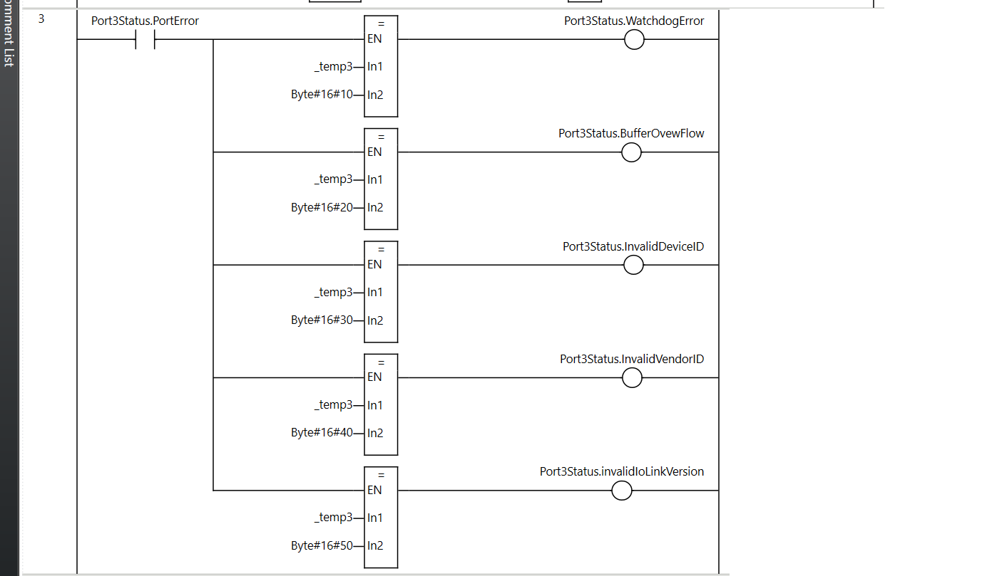
The error code is shown in the figure below.
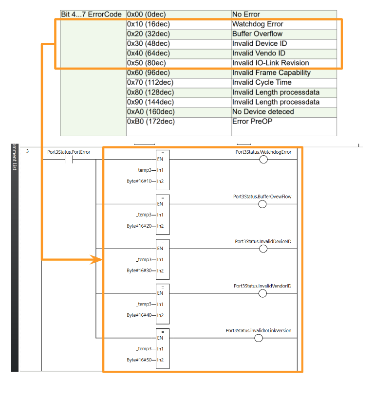
Rung4 Error Code‐2
Rung4 makes the appropriate variable True/False depending on the error code.

The error code is shown in the figure below.
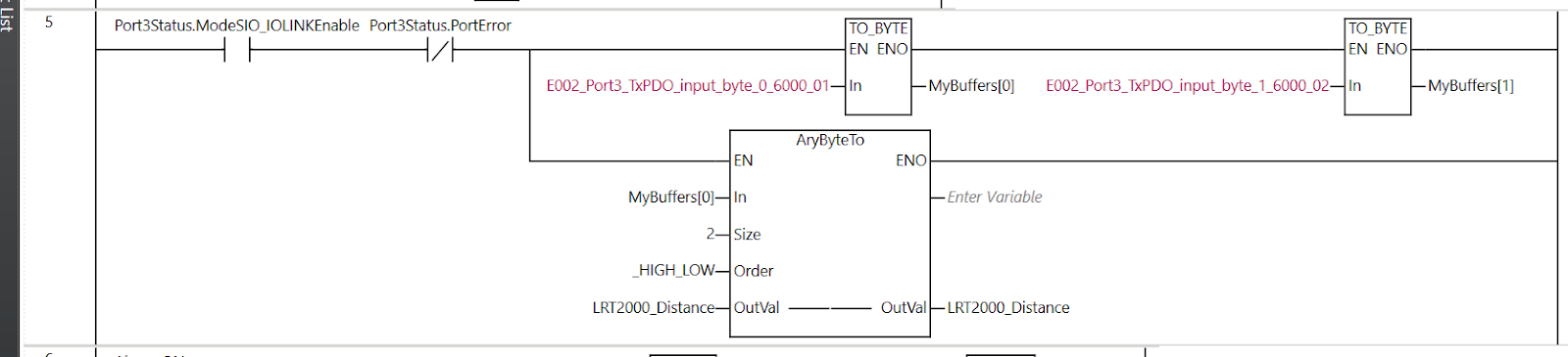
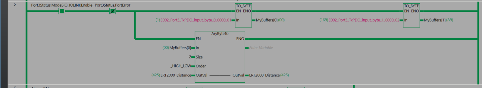
Rung5 Get LR-TB2000 Data
Rung5 converts the data taken via IO-LINK into BYTE and stores them in the BYTE array, and then moves them to LRT2000_Distance using the AryByteTo function.
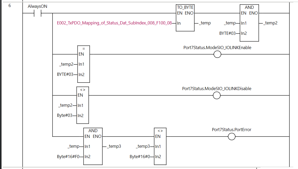
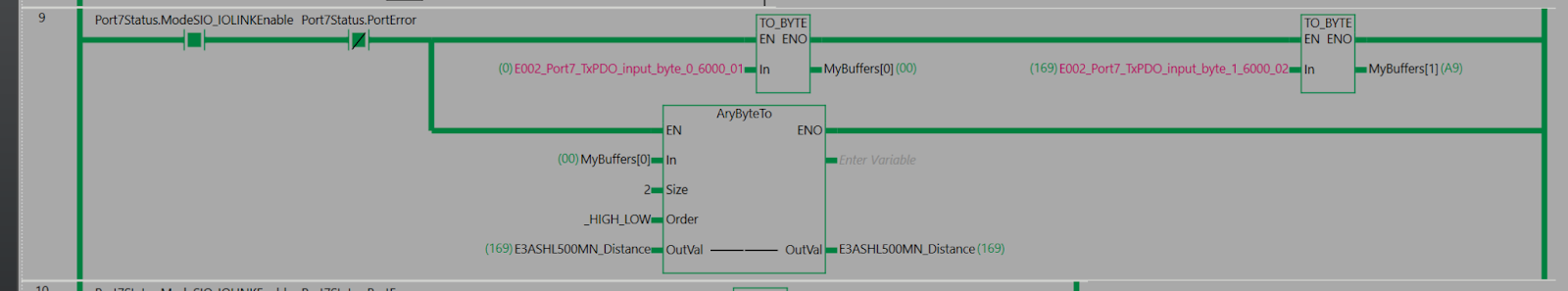
Rung6 Port7 Status
Rung6 determines if the Port is in normal IOLINK communication status based on the Port status data received by Murrelektronik IO-LINK Master.
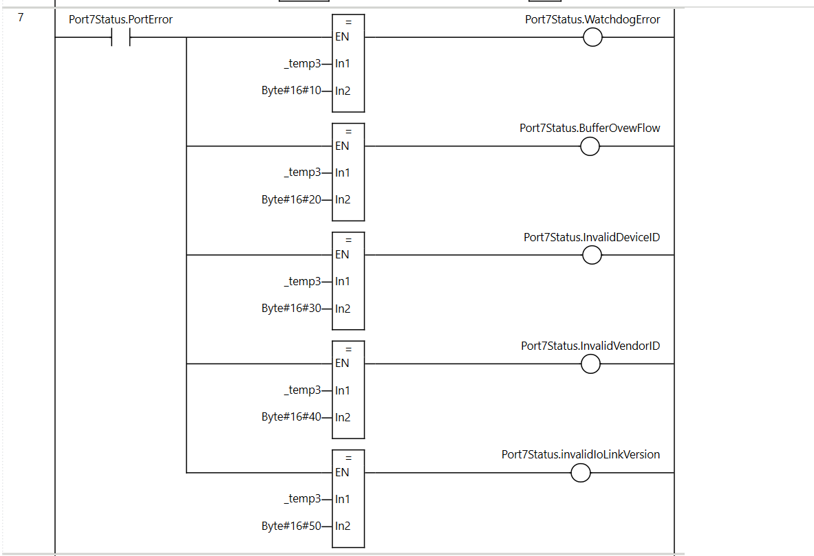
Rung7 Error Code-1
Rung7 makes the appropriate variable True/False depending on the error code.
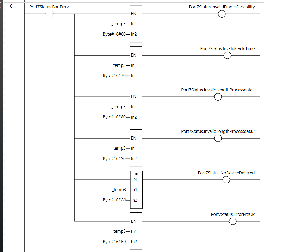
Rung8 Error Code-2
Rung8 makes the appropriate variable True/False depending on the error code.
Rung9 Get E3ASHL500MN Data
Rung9 converts the data taken via IO-LINK into BYTE and stores them in the BYTE array, and then moves them to E3ASHL500MN_Disance using the AryByteTo function.

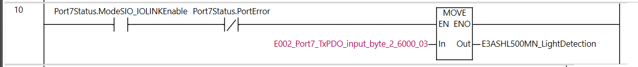
Rung10 Get E3ASHL500MN Data
Rung10 is the second Byte of the E3ASHL500MN, receiving the Light Detection from the IO-LINK Sensor.
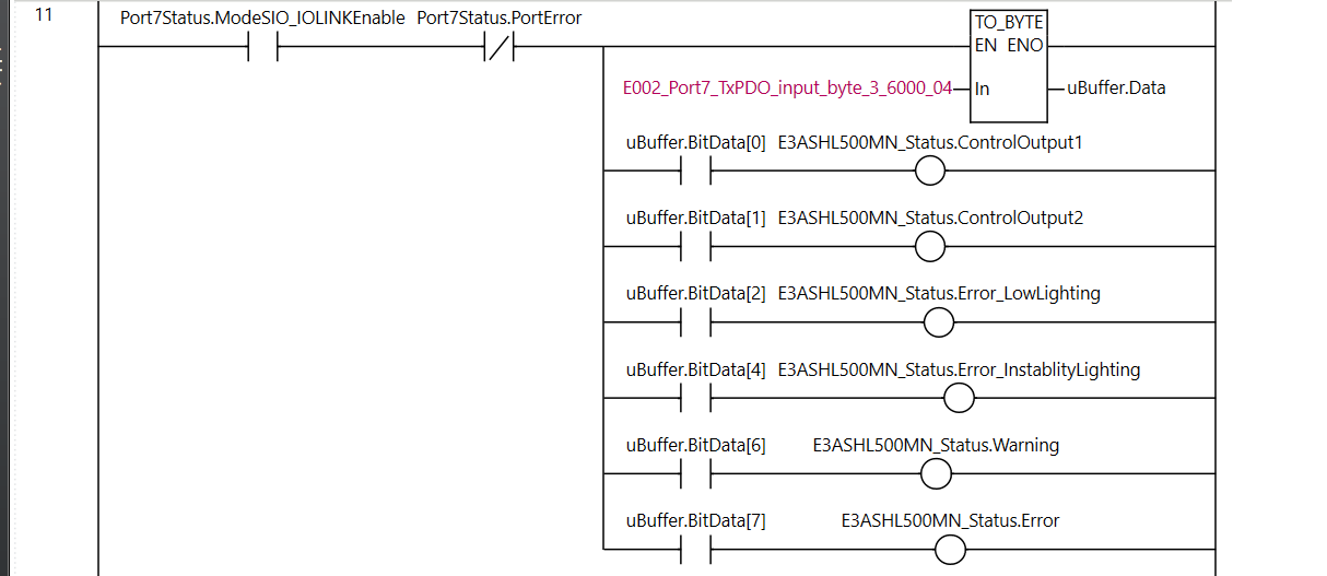
Rung11 Get E3ASHL500MN Data
Rung11 is the third Byte of the E3ASHL500MN, receiving the Status from the IO-LINK Sensor.
Rung12 Digital Input/Digital Output
Rung12 control whether the lamp is always ON or repeats ON/OFF for 1 second, depending on the digital input signal from Port6.
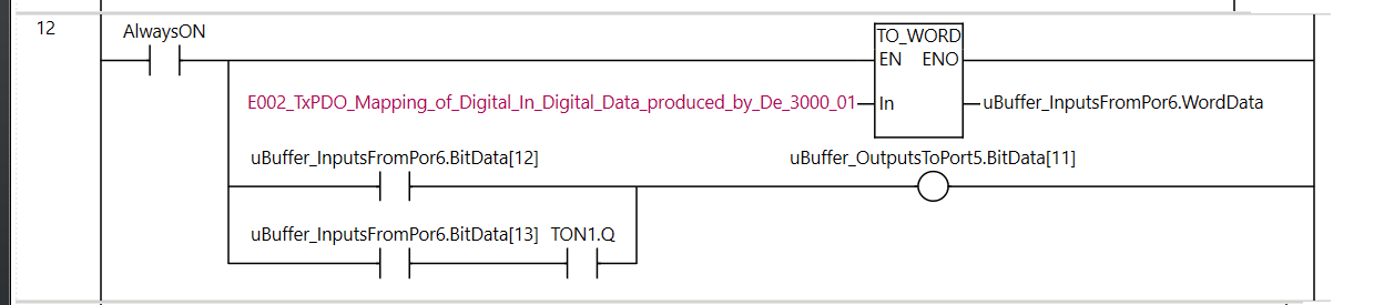
As shown in the figure below, Pin 4 of Port X6 is the 12th bit of data and Pin 2 is the 13th bit of data.
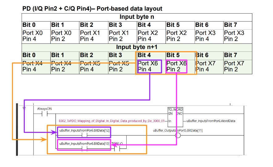
And the output Port X5 Pin4 is the 10th bit and Port X5 Pin2 is the 11th bit.
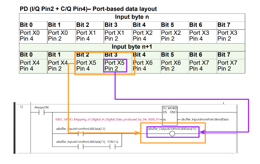
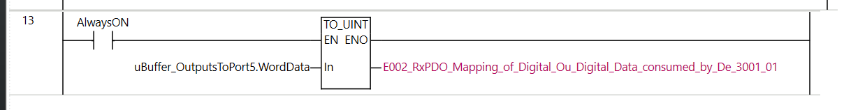
Rung13 Move Data
Rung13 moves Port5 DataBuffer to Process Data.
Online
Once you have finished programming, the next step is to transfer the project to the CPU.
Click on Online.

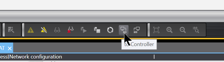
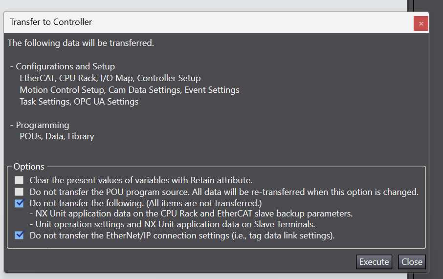
Download
Click “To Controller” to download the project to the CPU.
Proceed with Execute.
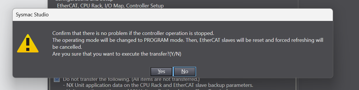
Proceed with Yes.
Just a second..

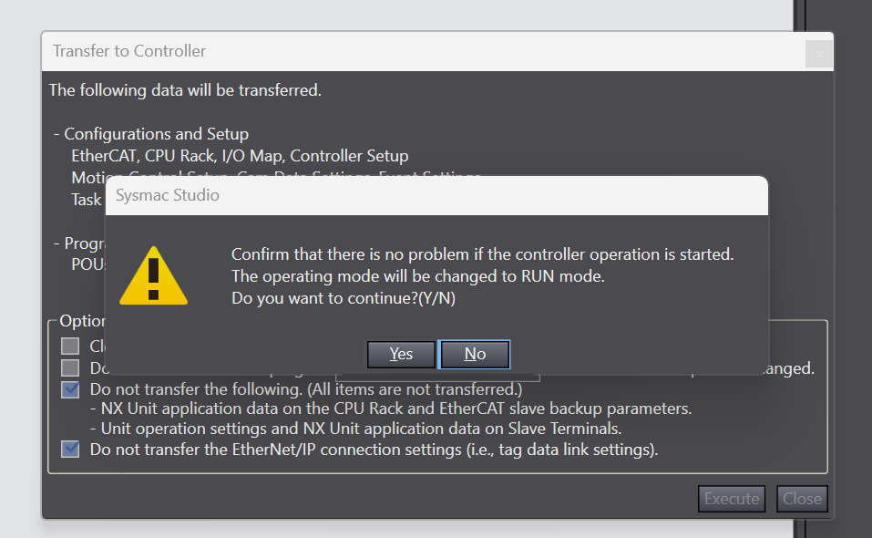
Press Yes to switche the CPU to Run Mode.
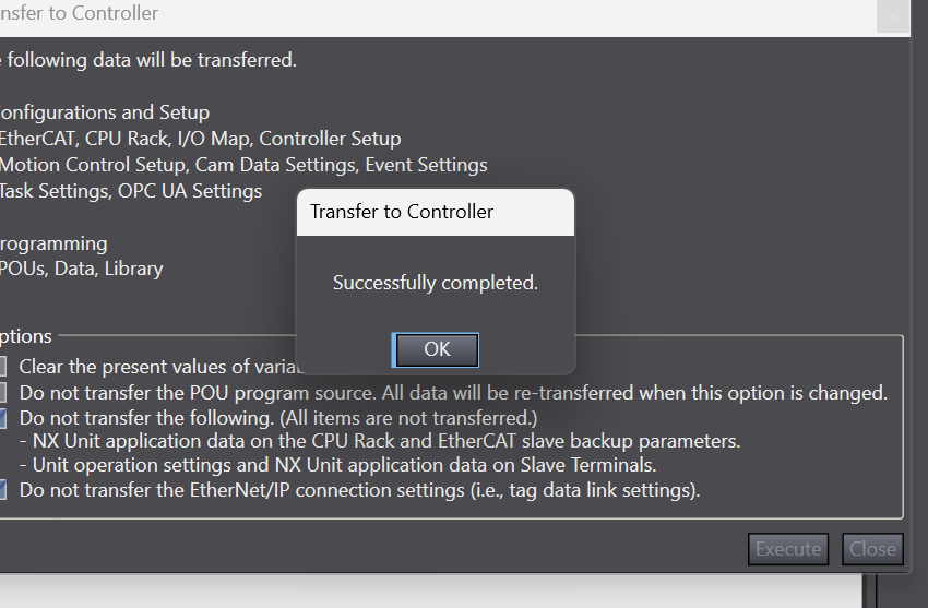
Done!
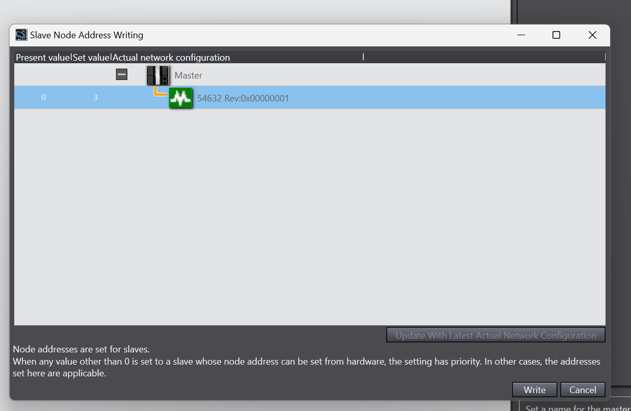
Write Slave Node Address
You need to write the Slave Node Address to Murreletronik, click on EtherCAT>Master>Write Slave Node Address.
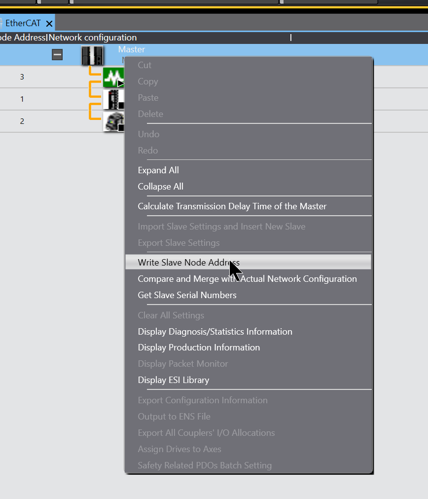
The Slave Node Address Writing operation screen appears.
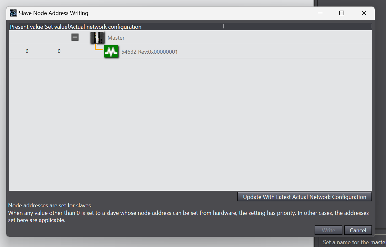
Click on the Field of Set Value.
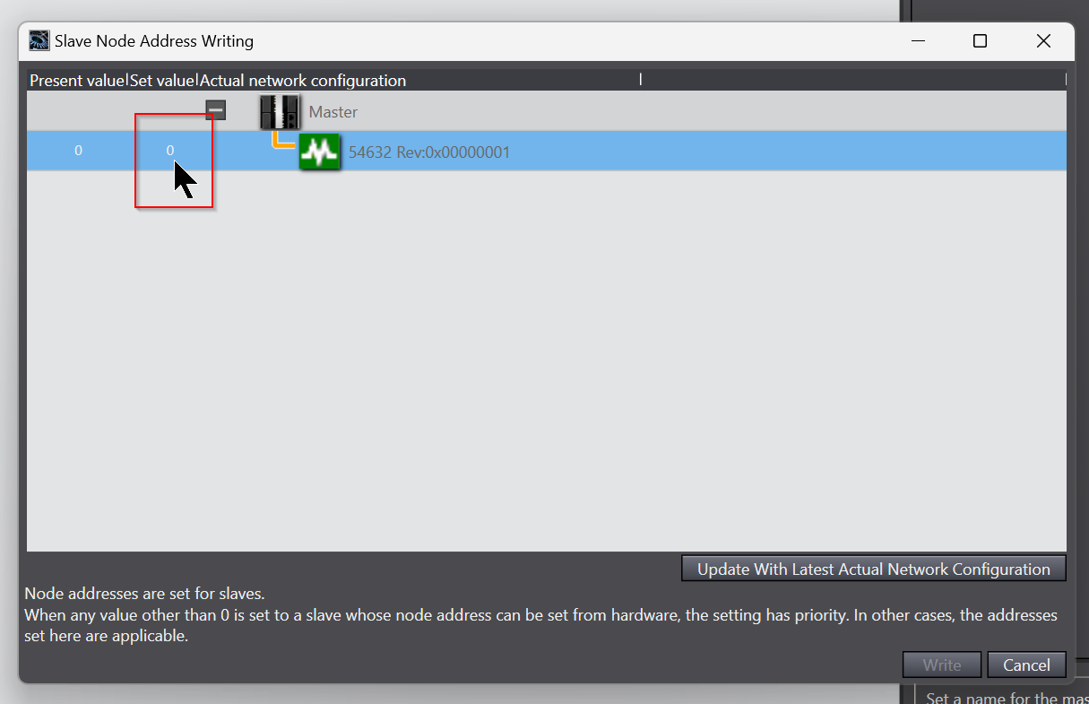
Enter the Node Address you wish to set for Murreletronik’s IO-LINK Master.
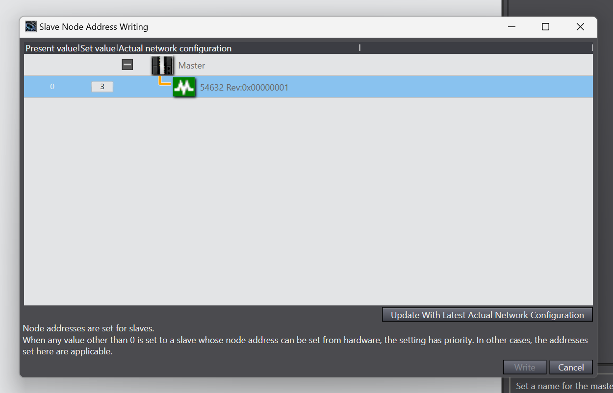
This is OK.
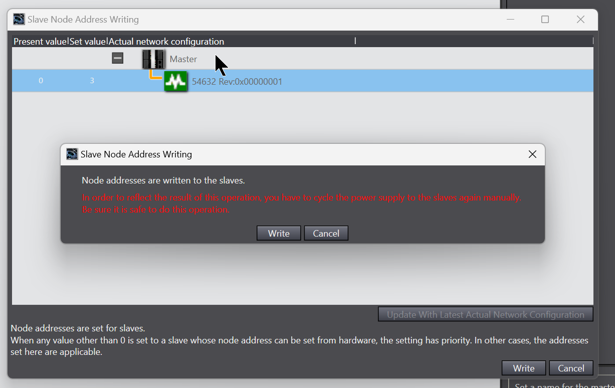
Write writes the Node Address.

Proceed with Write.
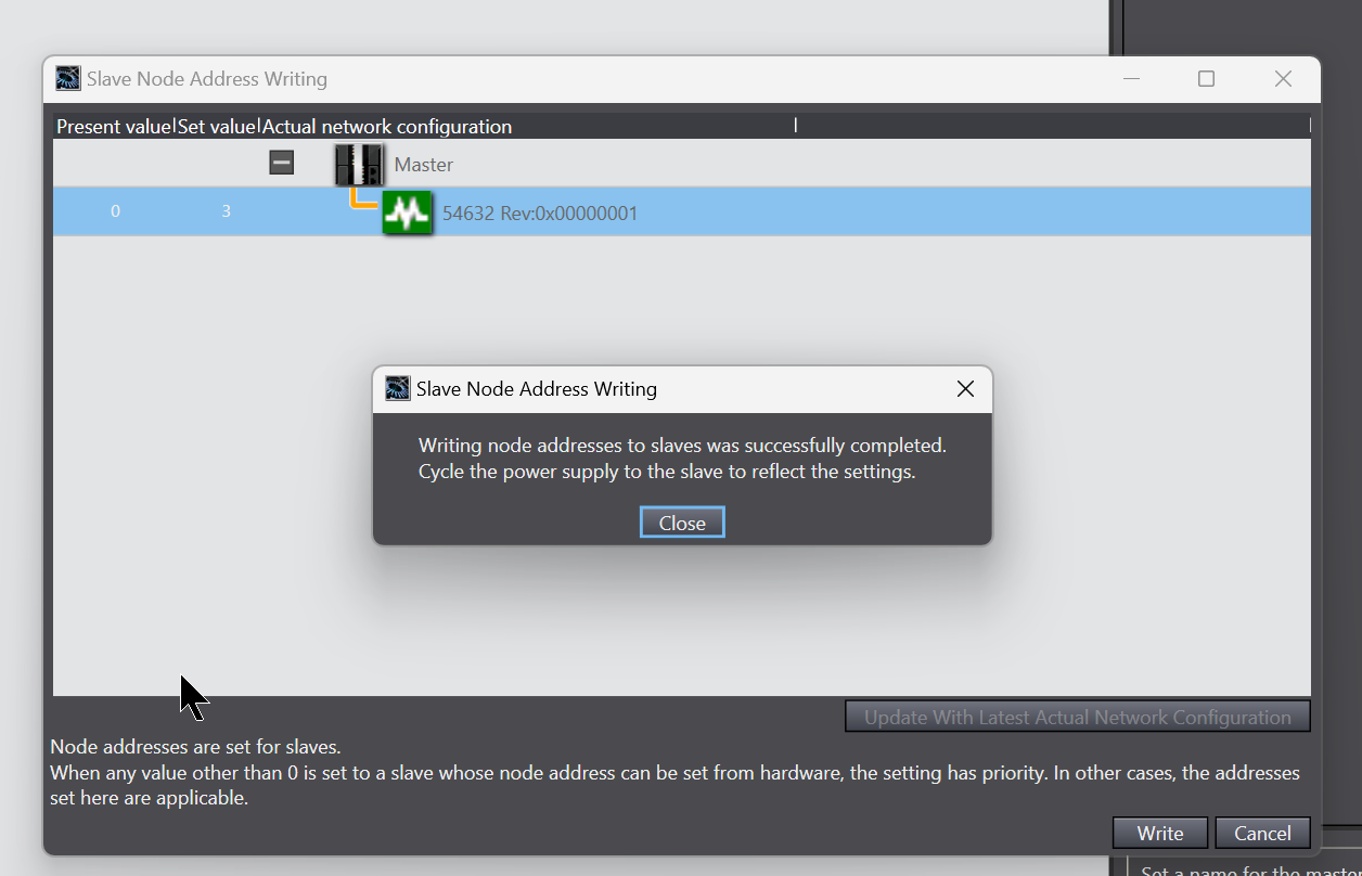
Done!
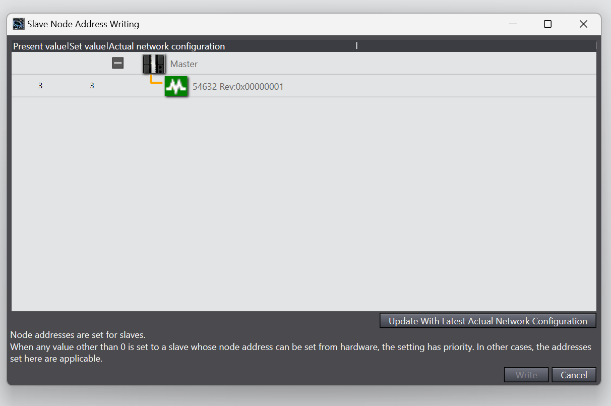
The present value of Murreletronik’s IO-LINK Master is now also 3.
Result
From Rung2, we can see that the IO-LINK communication status of Port3 is currently normal.
Likewise, the IO-LINK communication status from Rung6 to Port7 is currently normal.

You can check the measured distance values of the Keyence LRT2000 from Rung5.
You can check the measured distance values of Omron’s E3A3-HL500MN from Rung9.
Rung11からオムロンのE3A3-HL500MNの状態を確認できます。

Here is a video of the operation of Murreletronik’s digital inputs and outputs here.
OMRON .Connect with Murr EtherCAT IOLINK Master DIO Mode
Here is a video of the operation of Murreletronik’s IO-LINK device here.
OMRON .Connect with Murr EtherCAT IOLINK Master and OMRON IOLINK Sensor