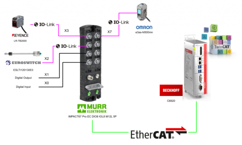
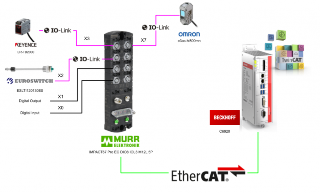
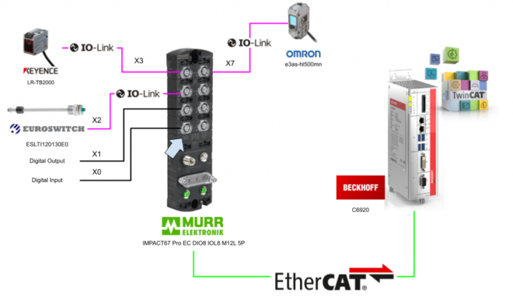
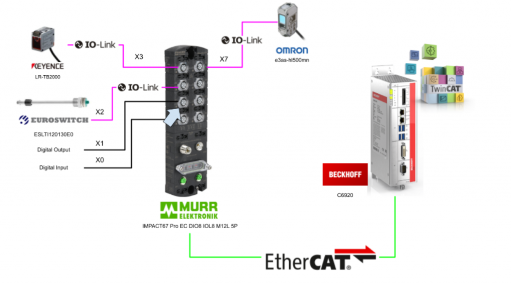
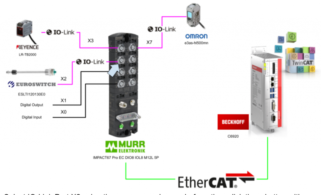
This article provides guidelines for connecting the Beckhoff TwinCAT3 and Murrelektronik IO-LINK Master.EtherCAT is Beckhoff’s C6920 and IO-LINK Device is Keyence’s LR-TB2000, OMRON’s E3AS-HL500MN and EUROSwitch’s Level Sensor.
Let’s get started!
Thanks!
This article was made possible thanks to equipment provided by Murrelektronik Turkey. Thank you very much.
Murrelektronik is a global company in the development, manufacturing and sales of automation solutions, divided into four core areas: power and control, interfaces, cables/connectors and IO systems. Murrelektronik is always offering high quality and innovative products to better serve our customers’ applications.

Office
Murrelektronik San. ve Tic Ltd Şti
Perpa Ticaret Merkezi A Blok Kat 11 No.1403
34384 Okmeydani/Istanbul/TR
Telephone
+90 212 2222298
E-Posta: info@murrelektronik.com.tr
About IO-Link
IO-Link is the ideal system for quick and easy integration of signals of all kinds, analog, digital I/O or IO-Link, and even those from different manufacturers can be connected and up and running in no time.
Murrelektroni’s goal is to build decentralized connectivity without a control panel and aims to use IO-Link to network the Controller down to the device level, even connecting directly to the cloud if necessary.
If the IO-Link device has been pre-configured, the device can be quickly brought up without importing IODDs or using a configuration tool.
IO-Link is a standardized protocol for connecting intelligent devices of sensors and actuators to automation systems.
Communication takes place between the IO-Link master and one or more IO-Link devices. The master module has one or more ports, and one device can be connected to each port. IO-Link is a point-to-point communication system, not a fieldbus.
And the IO-Link master module is the interface between the controller and the IO-Link system.

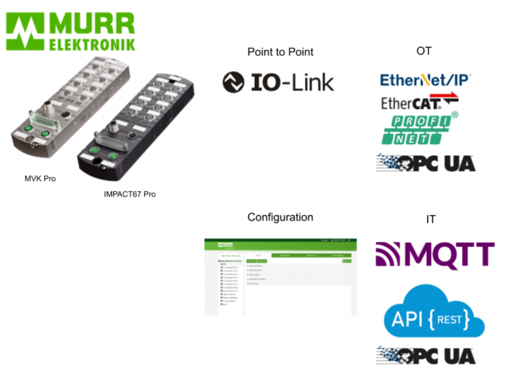
Compact IO-Link master With MURRelektronik
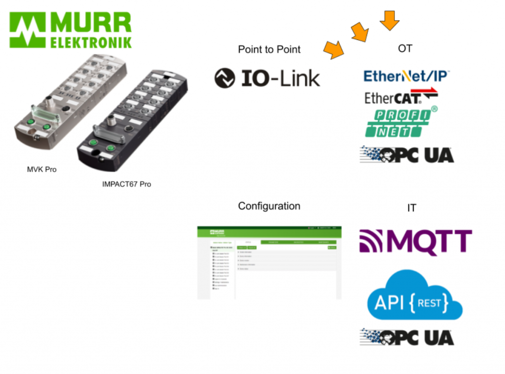
The compact IO-Link Master with eight multifunctional master ports is the easiest, most convenient, and quickest approach to connecting IO-Link devices. And the IP67-compliant module can replace complex wiring and expensive terminal boxes.
Flexible DIO-Link Ports
Eight multifunctional ports allow connection of all types of signals and can supply up to 4A per port to connected devices. (or can supply 1 Pin max. 2A)
Each Port can be configured as a digital input, digital output or IO-LINK Port.
(These modules can also be combined with IO-Link hub analog converters to increase flexibility while minimizing hardware cost.
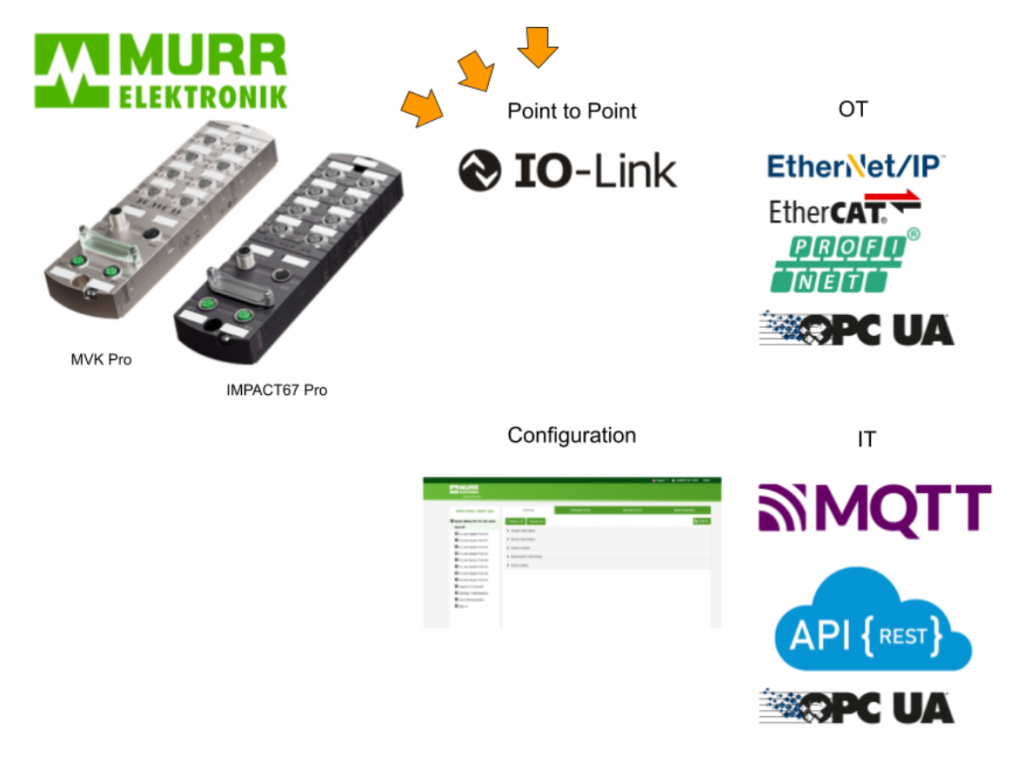
Protocol Support In OT Level
The module has two M12 D-Coded 100Mbps ports and can support any of the Industrial Protocols (PROFINET, Ethernet/IP, EtherCAT) that have the highest market share in the field, depending on the model. All IO-Link Master modules also have a built-in OPC UA Server for 3rd party access.
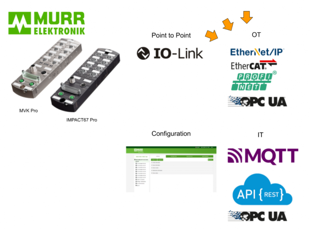
Ready for IIOT
The Standardized Master Interface (SMI) integrated into the IO-Link Master allows access to data via IIoT protocols such as OPC UA, JSON REST API, and MQTT.
The module can be configured via Webserver, Tools, OPC UA Server, JSON REST API, and MQTT. By using the IIOT Protocol, data can be immediately visualized.
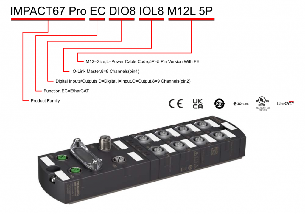
IMPACT67 Pro EC DIO8 IOL8 M12L 5P
The IMPACT67 Pro EC DIO8 IOL8 M12L 5P used in this article is an EtherCat device in a plastic housing with IP67 protection and two M12 ports (D-code) for connection to EtherCAT.
This IOLink Master supports AoE, EoE and FoE.
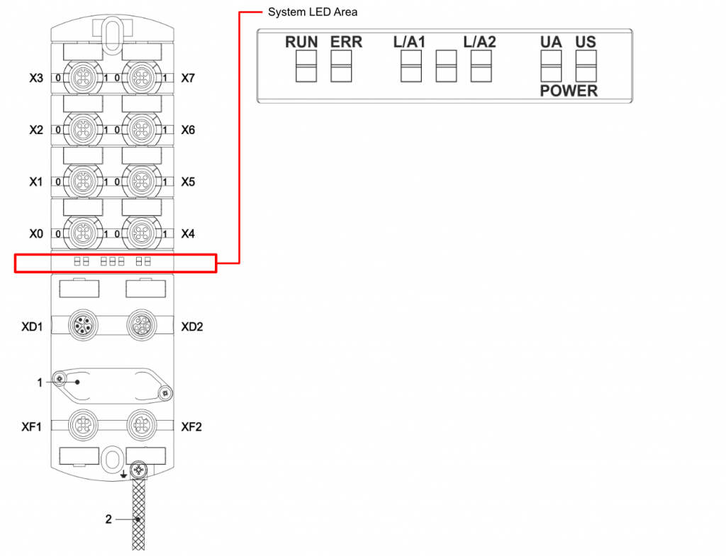
Layout
This is actually the Layout of IO-Link Master.
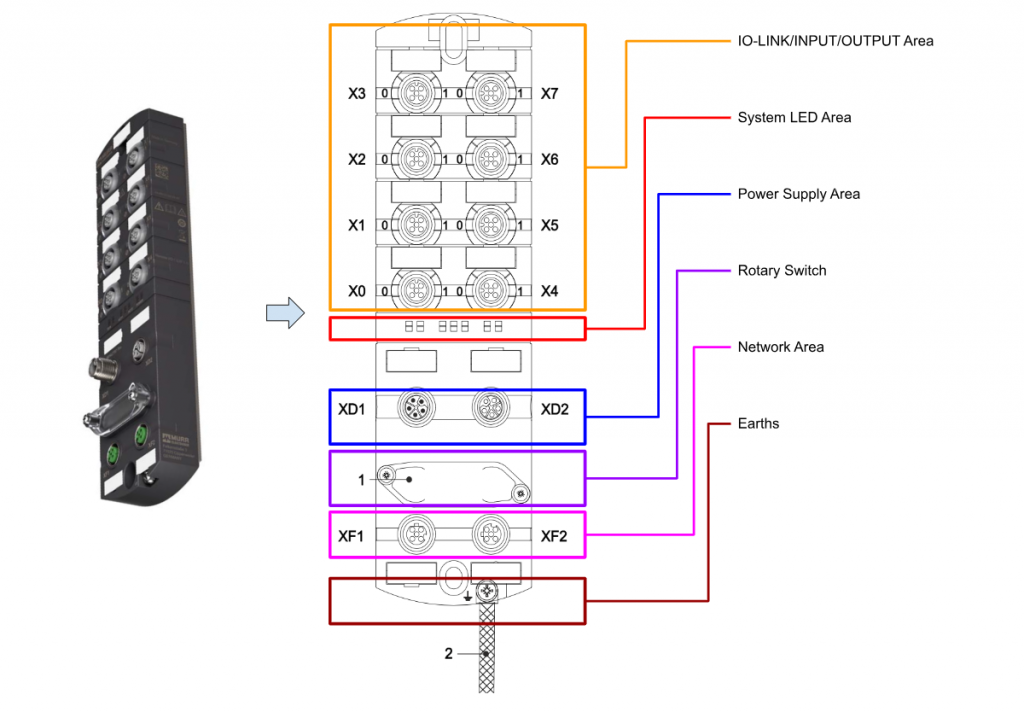
X0..X7
X0 to X7 are configurable IO-LINK, INPUT, and OUTPUT ports, which are M12 female A-Coded Connectors.
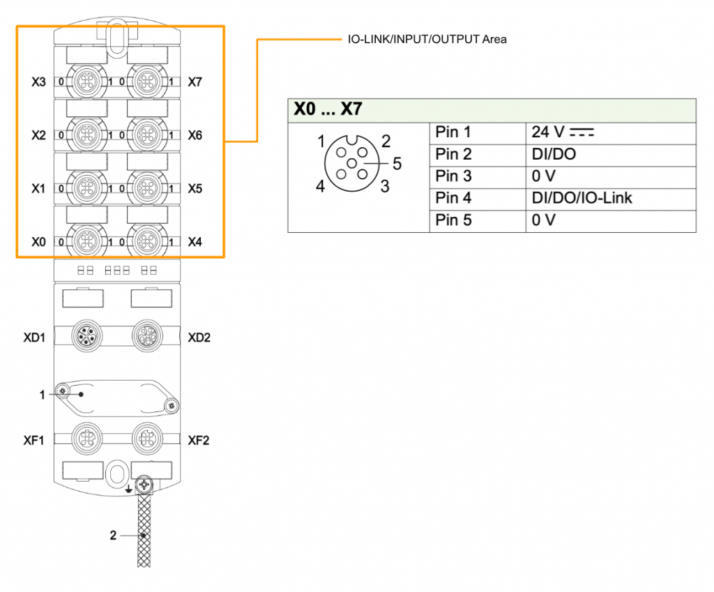
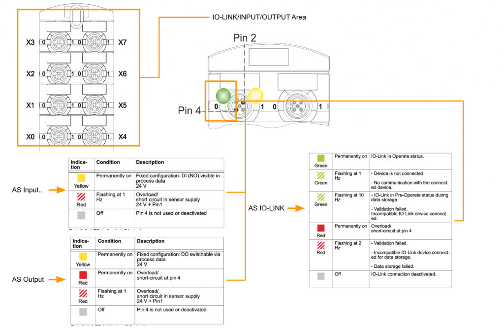
Each input/output is then assigned an individual status indicator. In the figure below, the 0 LED corresponds to Pin 4 of the corresponding Port, and the 1 LED indicates the status of Pin 2.This is the meaning of the LED for Pin 2.
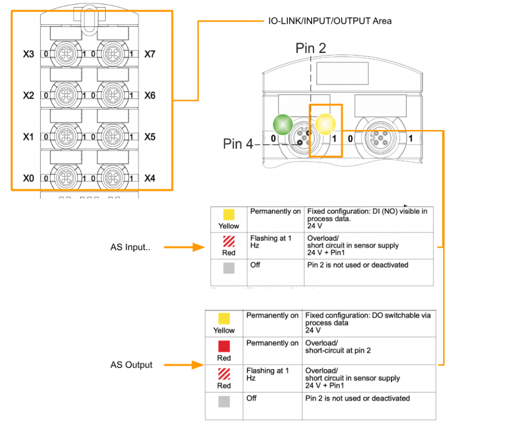
This is the meaning of Pin 4 LEDs.
XD1/XD2
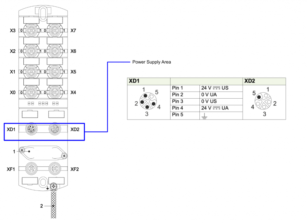
XD1 and XD2 are power IN/OUT ports of the module and use M12 L-Code.
XF1/XF2
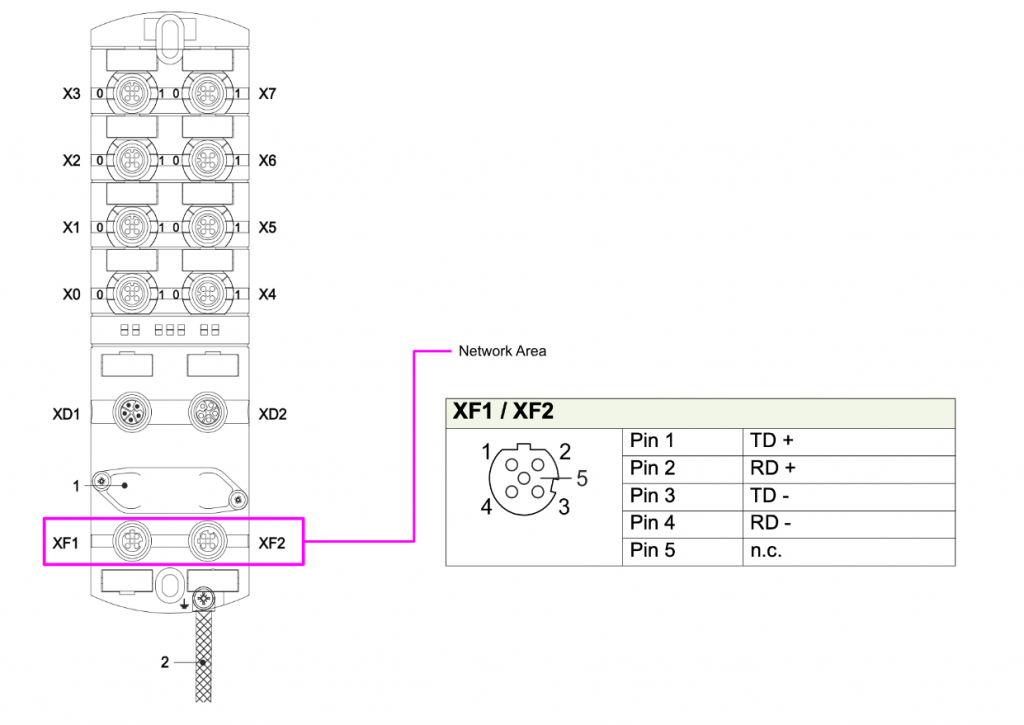
XF1/XF2 is an EtherCAT Network Port and uses the M12 female D-Code Connector.
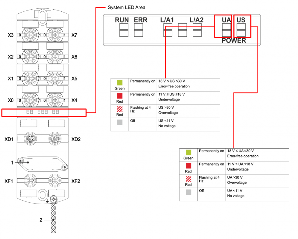
LED
There are several LEDs on the module that indicate current operating status, power supply, and other information.
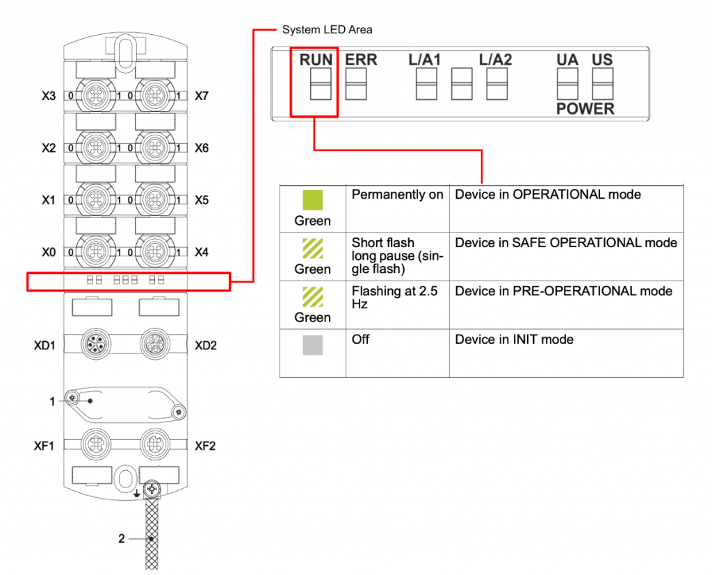
RUN
The RUN LED currently indicates the EtherCAT State Machine status of the module.
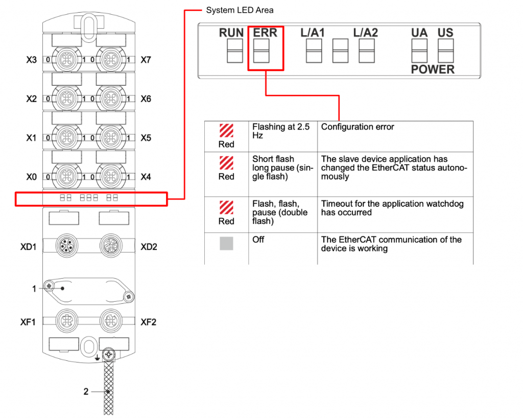
ERR
The ERR LED currently indicates a module fault condition.
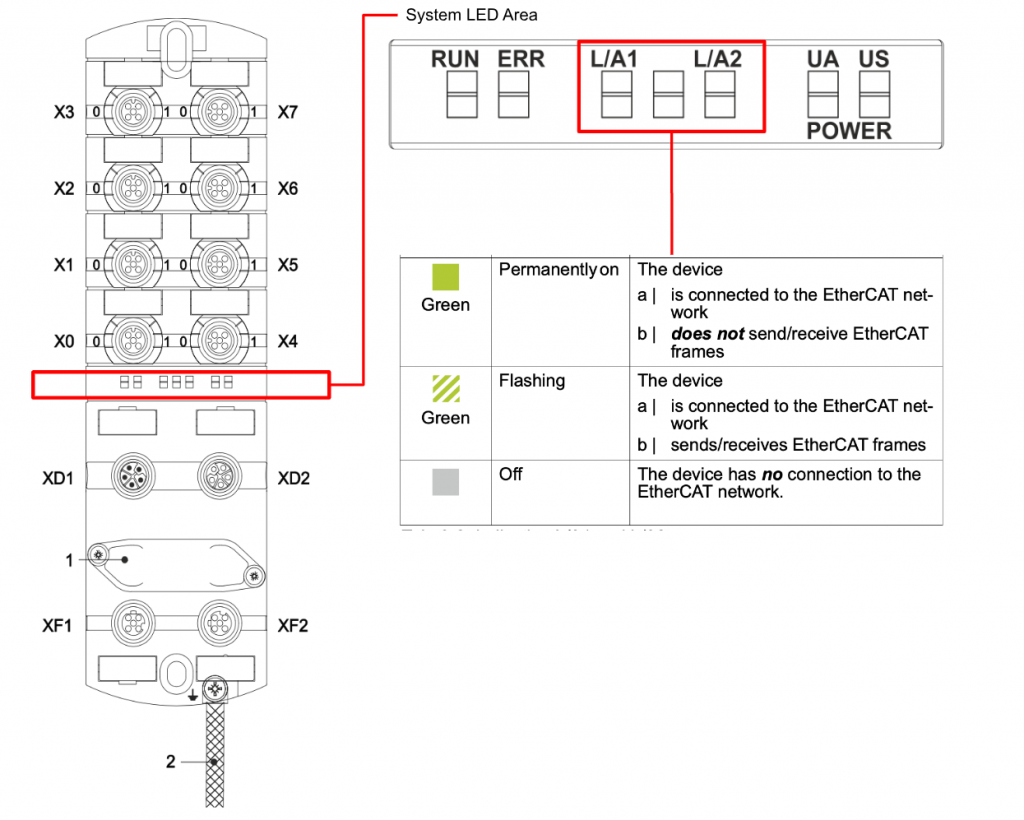
L/A1 L/A2
The LEDs here indicate the status of the EtherCAT network.
US/UA
These LEDs indicate the Sensor and Actuator power supplies of the module.
US=Sensor power, UA=Actuator power.
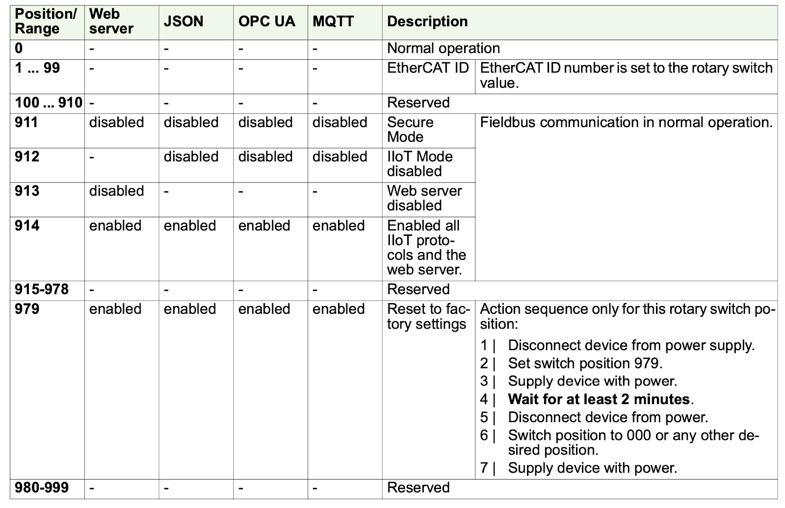
DIP Switch
Murrelektronik’s IO-LINK Master has DIP switches to set the IIOT function of the module.

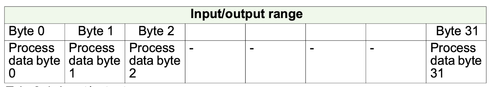
Process Data Mapping
IO-Link
Process data assignment for digital channels or IO-Link devices to pin 4.
If a slot is set to Digital IN or Digital OUT, one byte of process data is al- ways assigned to this slot.
DI
Process data assignment for digital inputs to pin 4 and pin 2
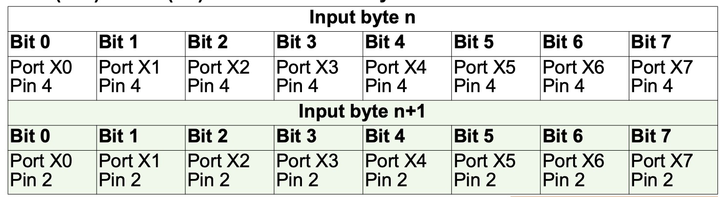
Pin4 (C/Q) + Pin2 (I/Q) – Port-based data layout
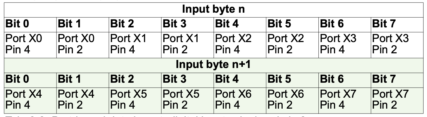
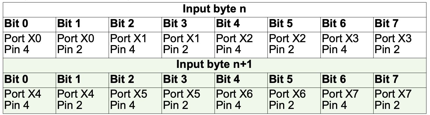
Pin4 (C/Q) + Pin2 (I/Q) – Pin-based data layout
DO
Process data assignment for digital outputs to pin 4 and pin 2.
PD (I/Q Pin2 + C/Q Pin4)– Port-based data layout
PD (I/Q Pin2 + C/Q Pin4) – Pin-based data layout

Implementation
Install IO-Link Device Tool
Next, download and install the IO-Link Device Tool Setup File from the link below.

Choose setup language>OK to proceed.

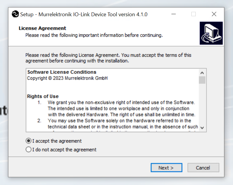
Agree to the license and proceed with Next>.
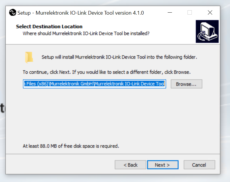
Set the path to install and press Next> to proceed.
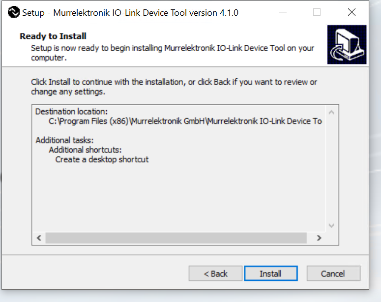
Next> to proceed.

Start with Install.
Just a second..
In some cases, the Firewall Link must be changed.

Done!
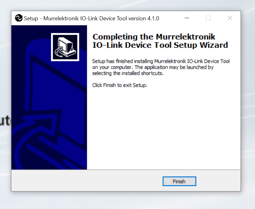
Murrelektronik IO-LINK Device Tool is now installed.

OMRON e3as-hl500lmn
This is the IO-LINK device e3as-hl500lmn that will be used in this project.
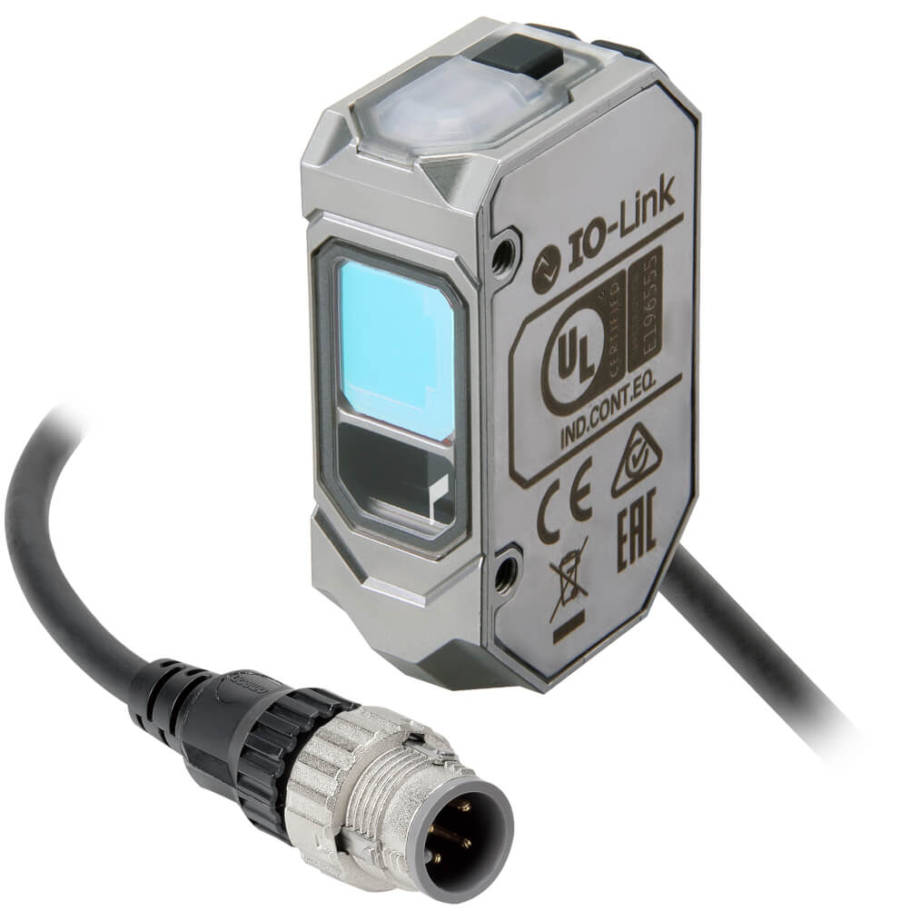
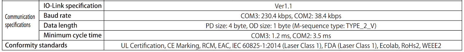
Process Input Data is 4 Bytes and Process Output Data is 1 Byte.
こちらはOMRON E3A3-HL500lMNのProcess Dataになります。
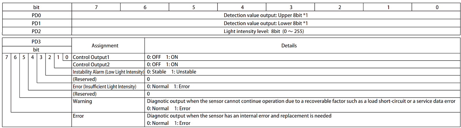
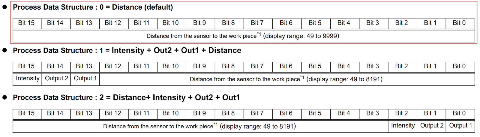
Keyence LR-TB2000
This is the IO-LINK device LR-TB2000 that will be used in this project.

デバイスには2BytesのProcess Inputがあります。

The distance measurement used in this case will be 2Bytes.
Murrelektronik Side
DIP Switch
This time, we will set it to 914 and enable Web server, JSON, OPC UA, and MQTT.
TwinCAT3 Side
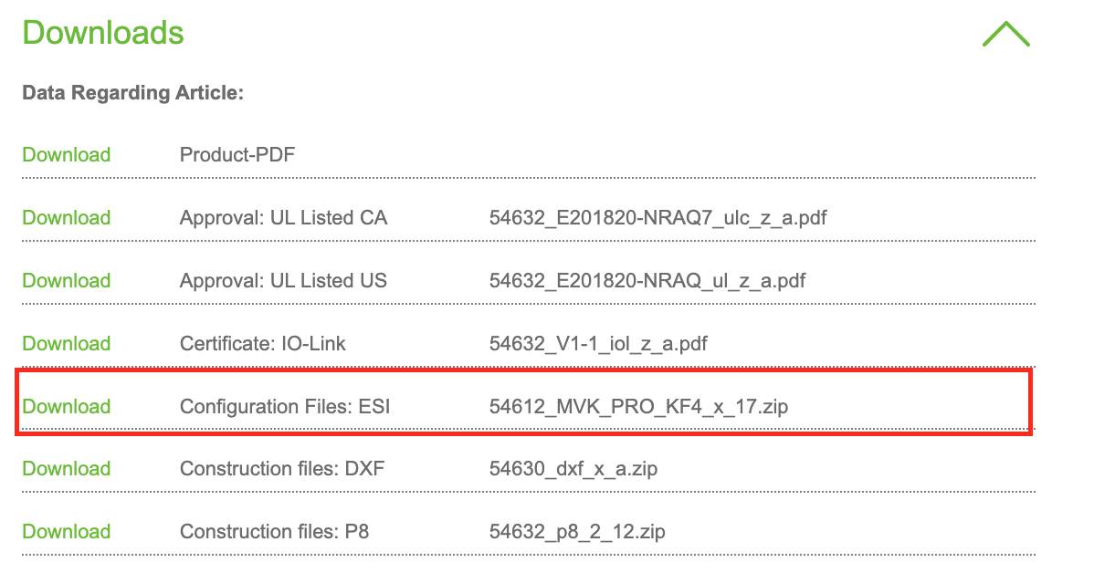
Download ESI File
Download the ESI File for IMPACT67 Pro EC DIO8 IOL8 M12L 5P from the link below.
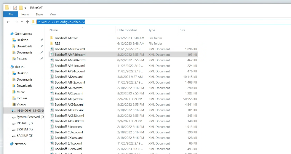
Install ESI File
Paste the ESI File into the following Path.
C:\TwinCAT\3.1\Config\Io\EtherCAT
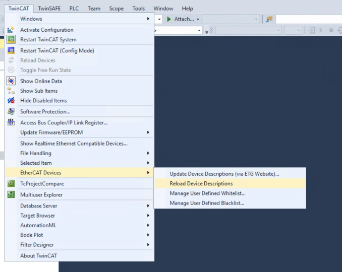
TReload the ESI File at winCAT>EtherCAT Devices>Reload Device Descriptions.
Add New Project
Create a new project at File>New>Project.
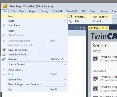
Select TwinCAT XAE Project (XML Format) and proceed with Ok.
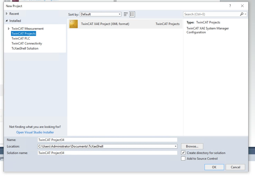
Done!New project created.
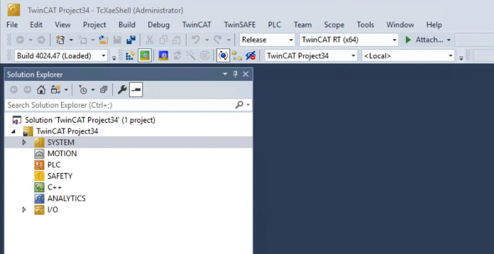
Add EtherCAT Master
To add the EtherCAT Master to the TwinCAT project, go to I/O>Devices>Add New Item.

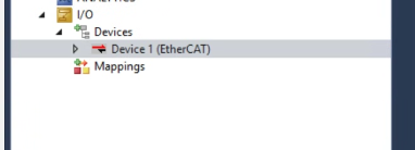
Select EtherCAT>EtherCAT Master and proceed with Ok.

Done!EtherCAT Master has been added.
Configure Network Adapter
Configure the Network Adapter to be used as an EtherCAT network.
Click on EtherCAT Master>Open the Adapter Tab.
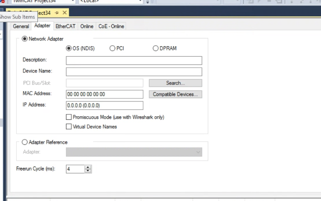
Search for IPC’s Network Interface in Search.
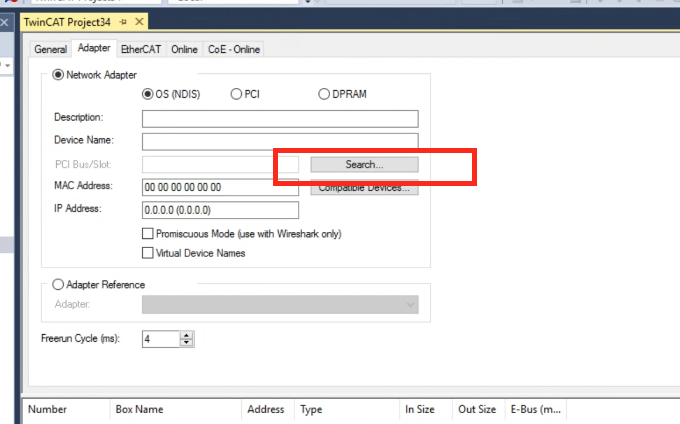
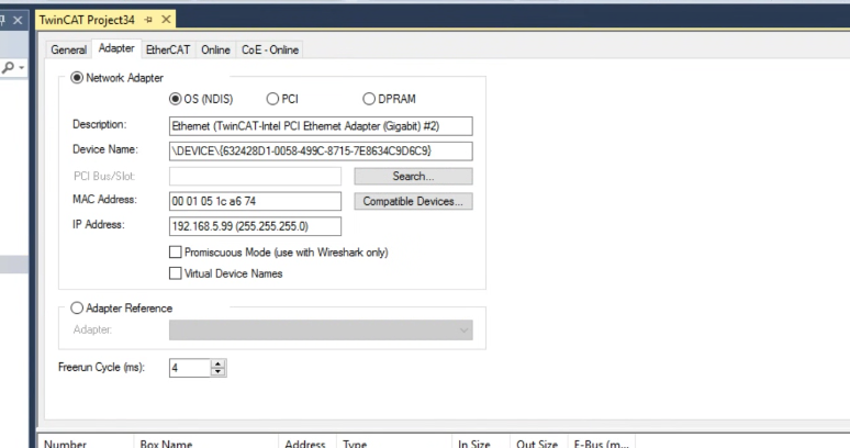
The Network Interfaces that can be used as EtherCAT Master in the IPC are displayed.

Done!
Add Murr EtherCAT Master
Next, to add the IMPACT67 Pro EC DIO8 IOL8 M12L 5P into the EtherCAT Network, go to EtherCAT>Right click>Add New Item.

Add IMPACT67 Pro EC DIO8 IOL8 M12L 5P from Murrelektronik GmbH.
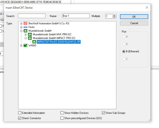
Done!

Configure IP
IMPACT67 Pro EC DIO8 IOL8 M12L 5P can support OPC UA Server, MQTT and REST API.
Click on Module>EtherCAT>Advanced Settings.
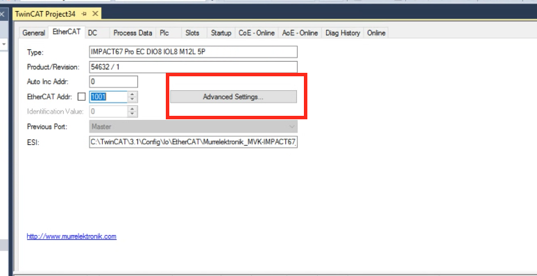
The Advanced Settings screen appears.
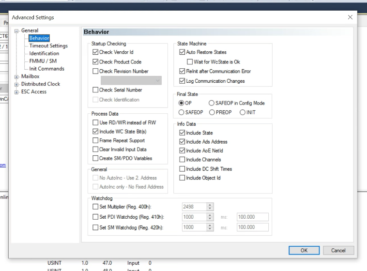
IP address can be set from Mailbox>EoE under IP port.

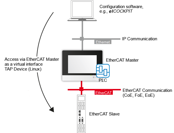
EoE?
EOE (Ethernet over EtherCAT) is part of the EtherCAT protocol and is used to support Ethernet communication between specific applications and devices, It enables data to be exchanged between end-user applications and EtherCAT devices using common Ethernet protocols, e.g. TCP/IP communication.
EOE allows end-user applications to communicate with devices in the EtherCAT network, thus enabling seamless integration of different devices and applications. EOE serves as a tool used to increase the flexibility and scalability of EtherCAT and to meet different communication requirements.
Configure Ports
Next, configure each Port on the IMPACT67 Pro EC DIO8 IOL8 M12L 5P.
Click on Box1 that was just added.
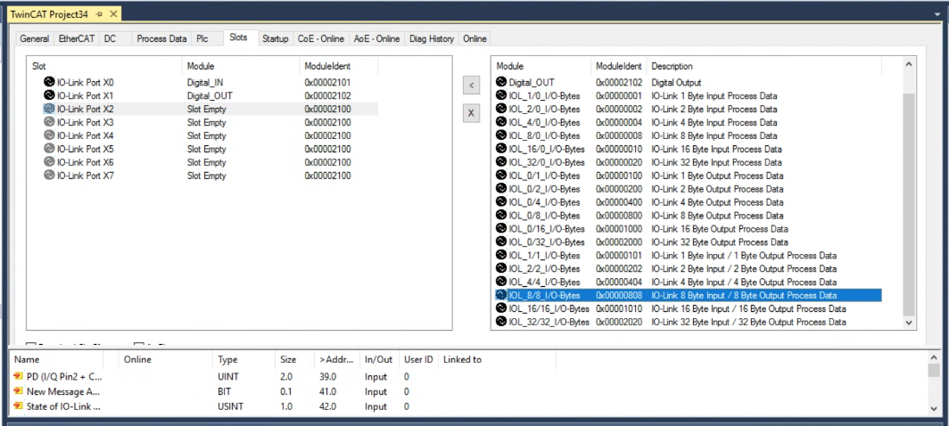
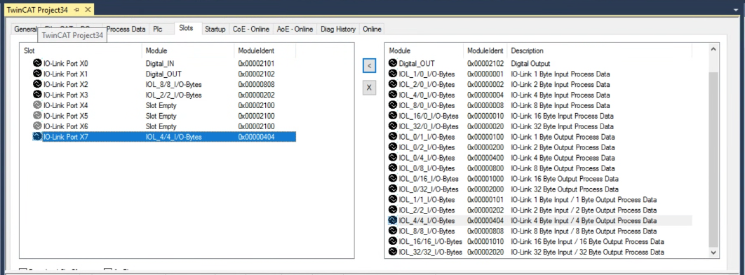
X0-X7 and each Port can be configured on the Slots screen.

Port X0
PortX0 will be set as a digital input.
In the Slots screen, each Default Port is also Empty.

Select IO-Link Port X0, then click the < button with Digital_IN selected for Module on the right.
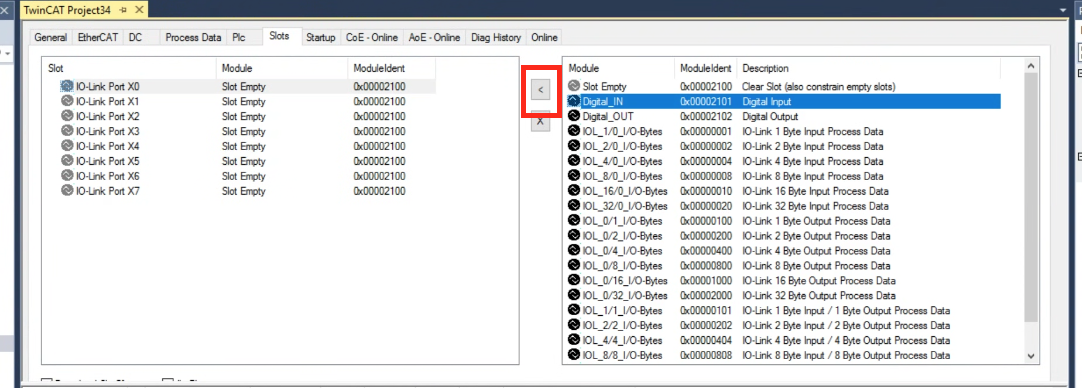
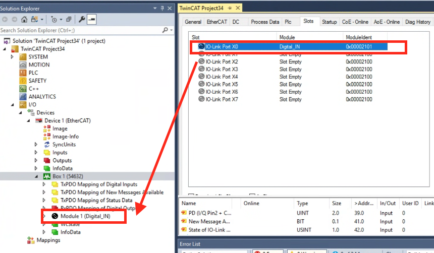
Done!Port X0 is now configured as a digital input, and Process Data for the digital input has been added to the box at the same time.。
Por tX1
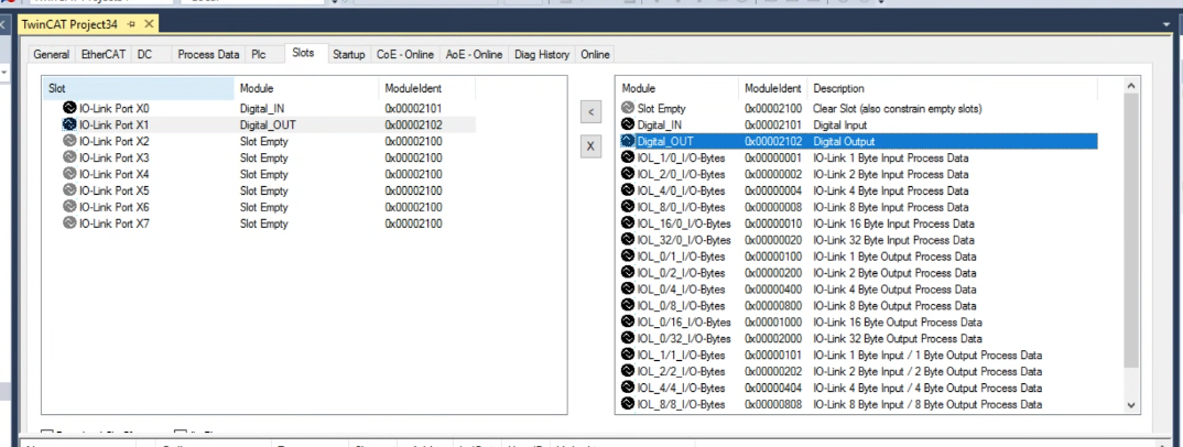
Port1 is a digital output.
Select IO-Link Port X1 using the same procedure as before, then click the < button with Digital_OUT selected for the Module on the right, and set Port1 as the digital output.
Port X2
Port 2 is the IO-LINK Port.
Select IO-Link Port X2 using the same procedure as before, then click the < button with IOL_8/8_I/O-Bytes selected for Module on the right, and set Port2 as the IO-LINK Port.
Port X3
Port 3 is an IO-LINK Port.
Select IO-Link Port X3 using the same procedure as before, then click the < button with IOL_2/2_I/O-Bytes selected for Module on the right, and set Port 3 as the IO-LINK Port.

Port X7
Port 7 is the IO-LINK Port.
Using the same procedure as before, select IO-Link Port X3, and with IOL_4/4_I/O-Bytes selected as the Module on the right, click the < button to set Port 4 as the IO-LINK Port.
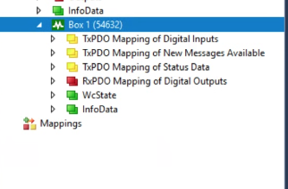
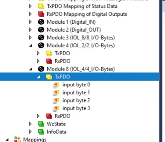
Process Data
Process Data is automatically added to PortX0/X1/X2/X3/X7.

Program
The next step is to create a program.
DUT
DUT_E3ASHL500
This structure corresponds to Omron’s EASHL500MN IO-LINK Sensor.
| TYPE DUT_E3ASHL500 : STRUCT _raw AT %I*:ARRAY[0..3]OF BYTE; END_STRUCT END_TYPE |
Function Block
FB_E3ASHL500
This Function corresponds to Omron’s EASHL500MN IO-LINK Sensor.
VAR
The _data variable is the structure defined earlier, which contains the Process Input Data for mapping to the EASHL500MN IO-LINK Sensor.
| FUNCTION_BLOCK FB_E3ASHL500 VAR_INPUT END_VAR VAR_OUTPUT END_VAR VAR _data:DUT_E3ASHL500; END_VAR |
Method_DetecedValue
The method here is the IO-LINK data of the EASHL500MN, the first 2 bytes are the measured distance, the LSB and HSB are SWAP’d to the format of the TwinCAT IPC.
| METHOD Method_DetecedValue : UINT VAR_INPUT END_VAR VAR _temp:ARRAY[0..1]OF BYTE; _value:UINT; END_VAR _temp[0]:=_data._raw[1]; _temp[1]:=_data._raw[0]; MEMMOVE( destAddr:=ADR(_value) ,srcAddr:=ADR(_temp) ,n:=2 ); Method_DetecedValue:=_value; |
Method_LightingIntensityLevel
This Method can acquire the IO-LINK data of EASHL500MN, 0 and 1 eye light intensity.
| METHOD Method_LightingIntensityLevel : USINT VAR_INPUT END_VAR Method_LightingIntensityLevel:=BYTE_TO_USINT(_data._raw[2]); |
PROPERTY Prop_Error : bool GET
This Method here can obtain the error status from the IO-LINK data of the EASHL500MN, the 3rd Byte of Status data.
| Prop_Error:=_data._raw[3].2 OR _data._raw[3].4 OR _data._raw[3].6 OR _data._raw[3].7; |
PROPERTY Prop_OutputStatus1 : bool GET
This Property here returns output 1 of EASHL500MN.
| Prop_OutputStatus1:=_data._raw[3].0; |
PROPERTY Prop_OutputStatus2 : bool GET
This Property here returns output 2 of EASHL500MN.
| Prop_OutputStatus2:=_data._raw[3].1 |
FB_LRT2000
This Function corresponds to Keyence’s LRT2000 IO-LINK Sensor.
VAR
The _data variable is the Process Input Data to be mapped to EKeyence’s LRT2000 IO-LINK Sensor.
| FUNCTION_BLOCK FB_LRT2000 VAR_INPUT END_VAR VAR_OUTPUT END_VAR VAR _data AT %i*:ARRAY[0..1]OF BYTE; END_VAR |
Method_Distance : UINT GET
The Method here is the IO-LINK data of the LRT2000, 2Bytes is the measured distance, and the LSB and HSB are SWAP’d to the format of the TwinCAT IPC.
| METHOD Method_Distance : UINT VAR_INPUT END_VAR VAR _temp:ARRAY[0..1]OF BYTE; _value:UINT; END_VAR _temp[0]:=_data[1]; _temp[1]:=_data[0]; MEMMOVE( destAddr:=ADR(_value) ,srcAddr:=ADR(_temp) ,n:=2 ); Method_Distance:=_value; |
MAIN
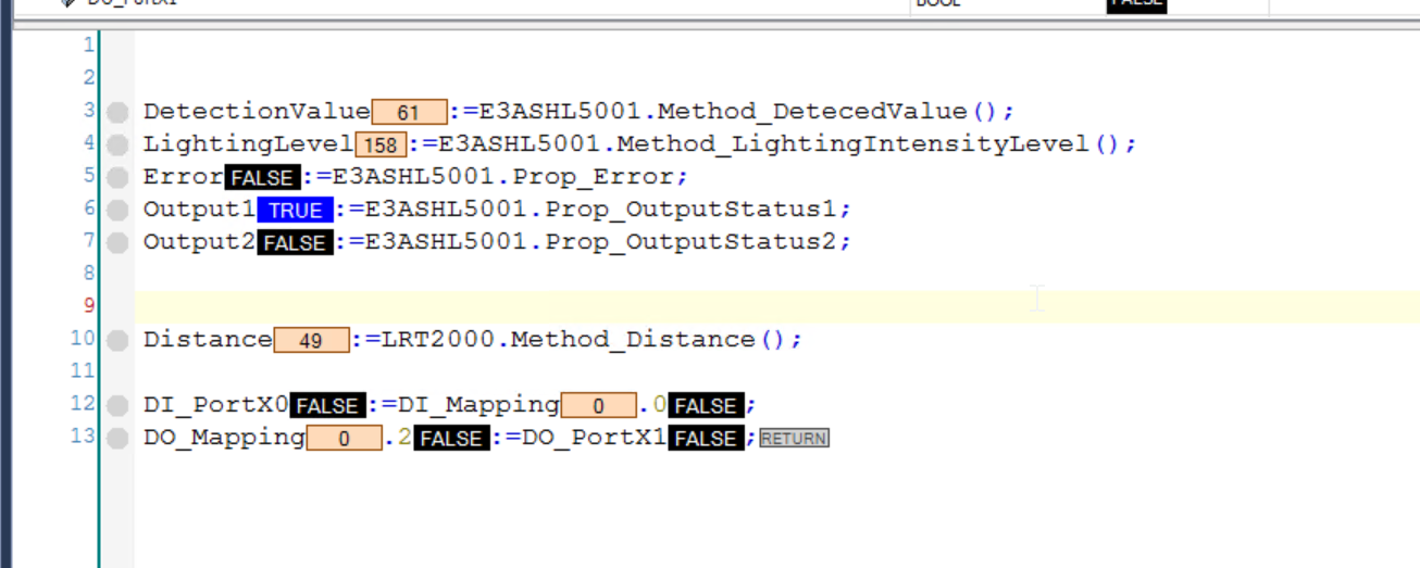
This program takes data from each IOLINK device.
| PROGRAM MAIN VAR E3ASHL5001:FB_E3ASHL500; DetectionValue:UINT; LightingLevel:USINT; Error:BOOL; Output1,Output2:BOOL; LRT2000 :FB_LRT2000; Distance:UINT; DI_PortX0,DO_PortX1:BOOL; DI_Mapping AT %I*:UINT; DO_Mapping AT %Q*:UINT; END_VAR DetectionValue:=E3ASHL5001.Method_DetecedValue(); LightingLevel:=E3ASHL5001.Method_LightingIntensityLevel(); Error:=E3ASHL5001.Prop_Error; Output1:=E3ASHL5001.Prop_OutputStatus1; Output2:=E3ASHL5001.Prop_OutputStatus2; Distance:=LRT2000.Method_Distance(); DI_PortX0:=DI_Mapping.0; DO_Mapping.2:=DO_PortX1; |
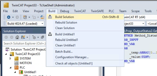
Build
Compile the project under Build>Build Solution.
Link the Variables
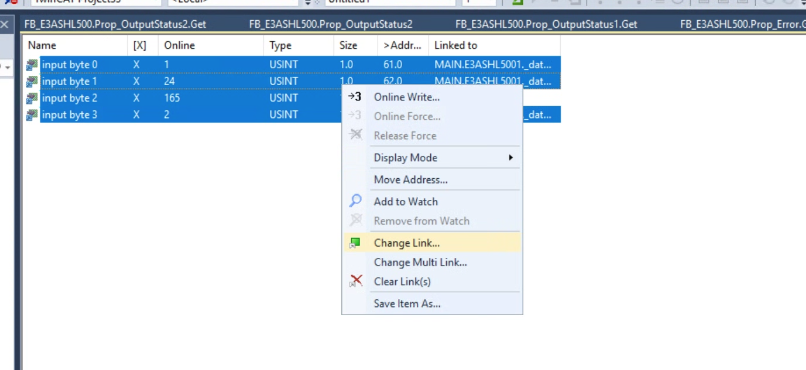
Finally, let’s tie the Process Input and Process Output variables for each Port to the program.
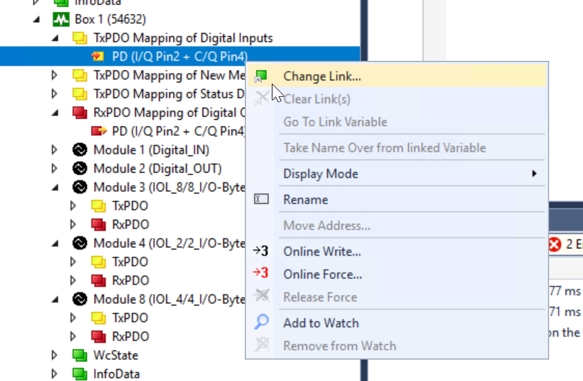
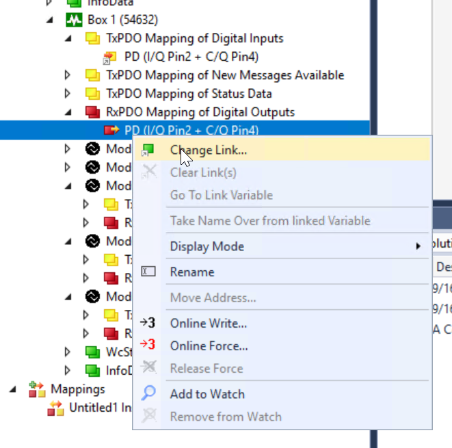
Select all variables you want to map > right click > Change Link.
Mapping of digital inputs should be linked to TxPDO Mapping of Digital Inputs>PD (I/Q Pin2 +C/Q Pin4).
Mapping of digital outputs should be linked to TxPDO Mapping of Digital Outputs>PD (I/Q Pin2 +C/Q Pin4).
The same data Bytes of Process data will be displayed in the User Program, so let’s map the variables appropriately.

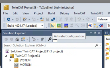
Activate
Download the Hardware Configuration to TwinCAT Runtime with Activate Configuration.
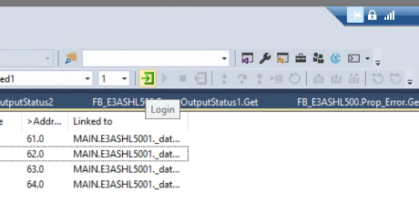
Login
Click Login to download the User Program to TwinCAT Runtime.
Result
From IO-LINK Device Tool
First check the status of the IMPACT67 Pro EC DIO8 IOL8 M12L 5P from the Murrelektronik IO-Link Device Tool.
just a second..
Search
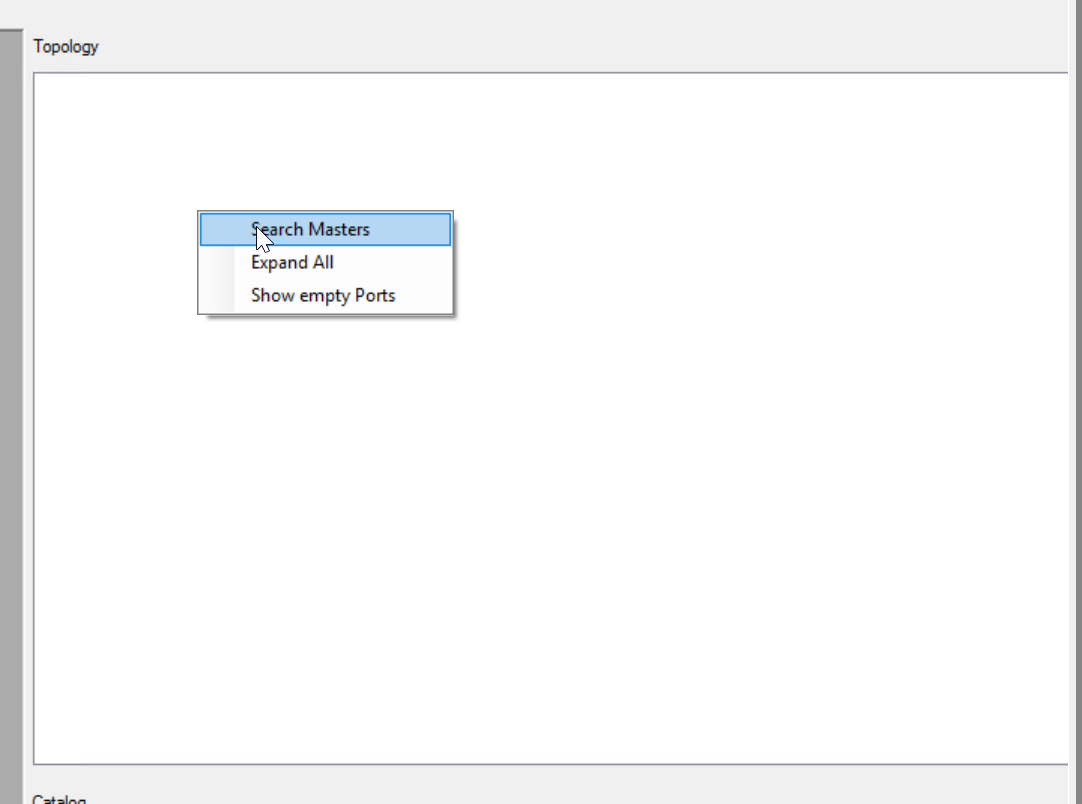
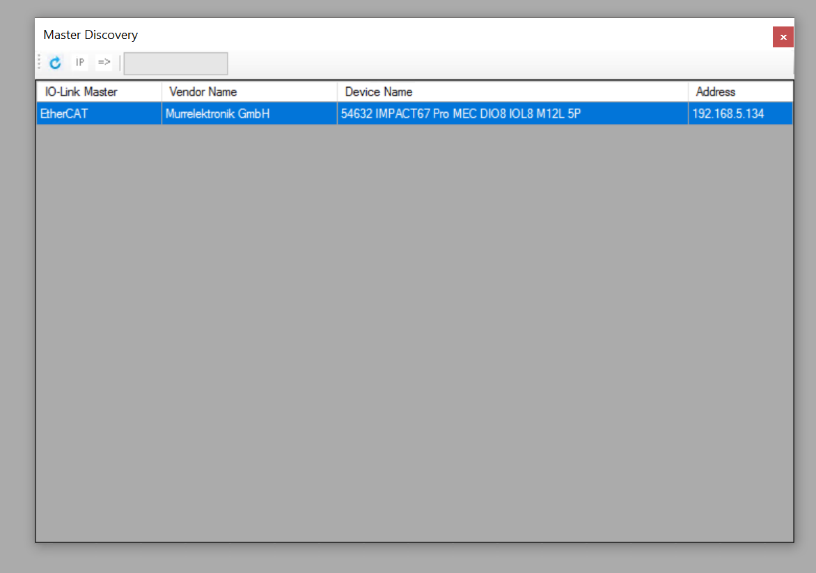
Launch the Murrelektronik IO-Link Device Tool and search for IMPACT67 Pro EC DIO8 IOL8 M12L 5P under Topology>Search Masters on the right.
If you cannot find it, use the Search IP Address function to search for IMPACT67 Pro EC DIO8 IOL8 M12L 5P.
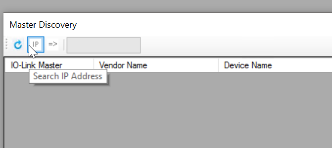
Enter the IP address of the IMPACT67 Pro EC DIO8 IOL8 M12L 5P and proceed with Ok.
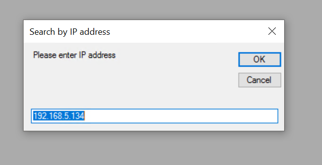
Done!IMPACT67 Pro EC DIO8 IOL8 M12L 5P found.
Right-click on the searched IMPACT67 Pro EC DIO8 IOL8 M12L 5P > Assign to move the device to the project.
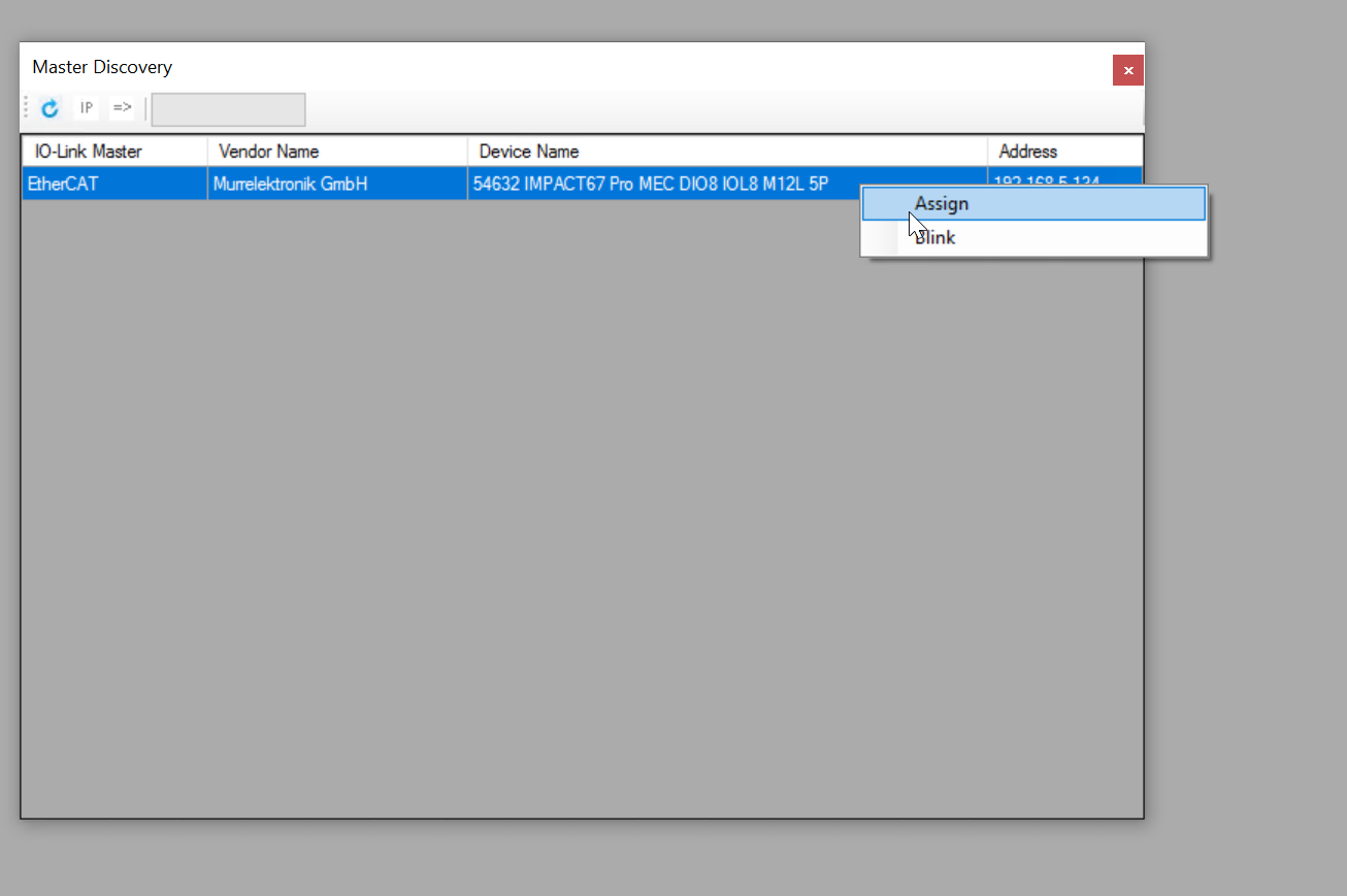
Done!
Import IODD
From the IODD Finder, select Options>Import IODD to import each company’s IO-LINK devices into the tool.

The Import IODD screen appears.

Next, set the Folder Path for the Import IODD from the … button.
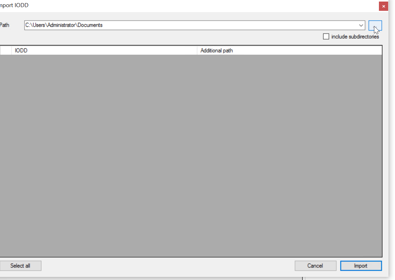
Sets the storage location for the IODD Folder.

Checkbox for Include subdirectories.
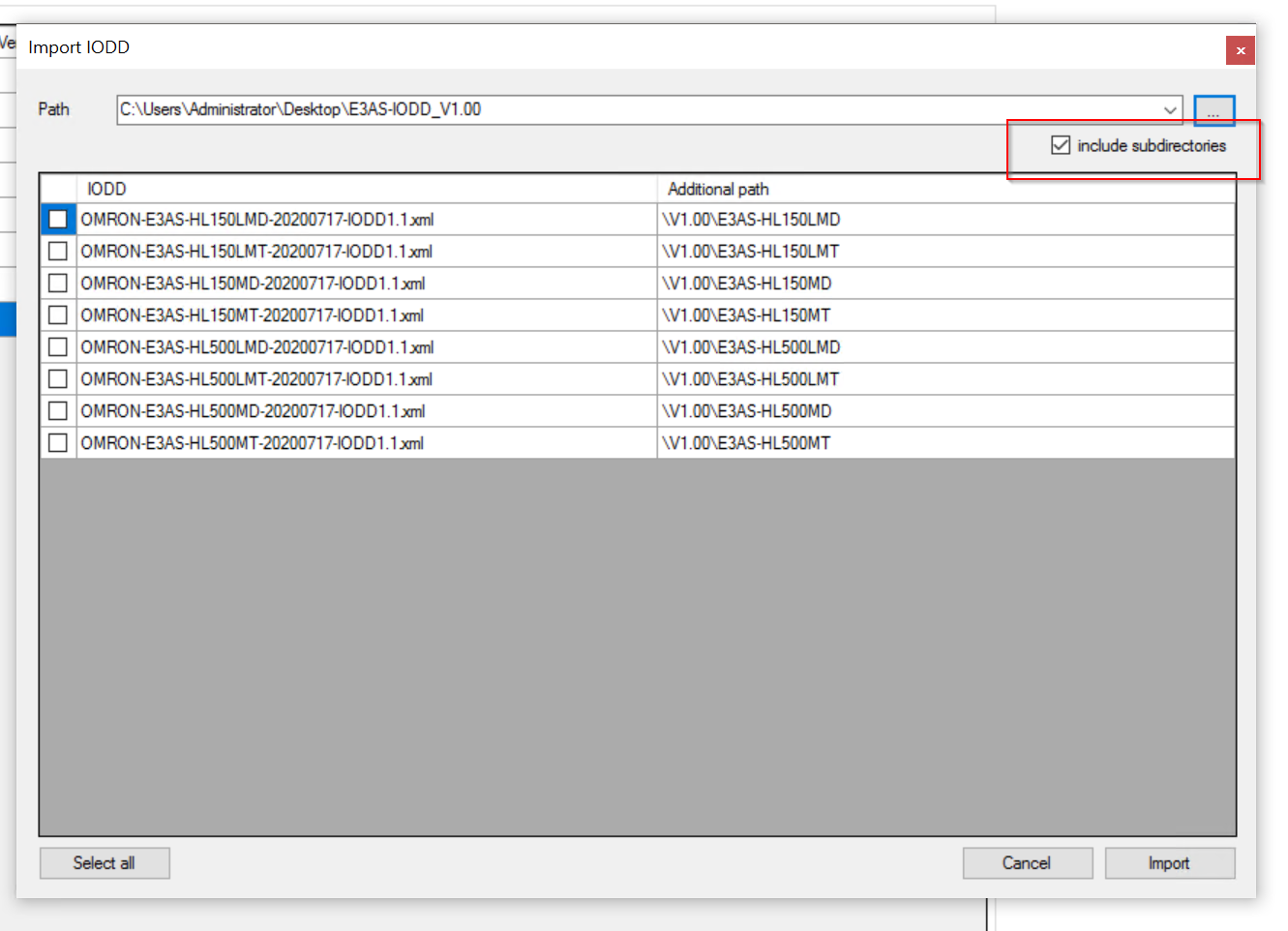
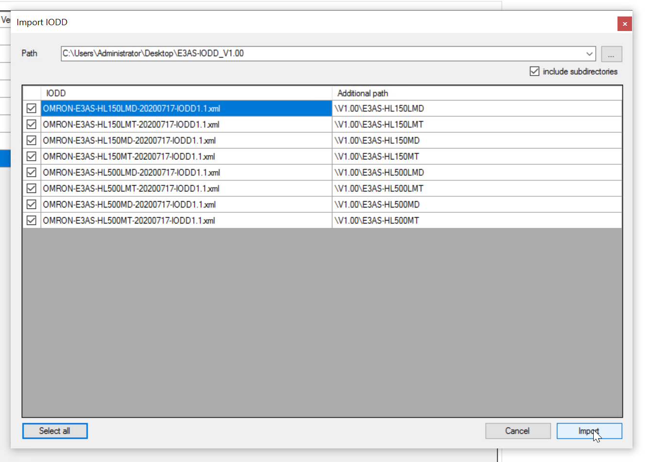
Check the IODD File to be imported and import it.
Go Ooline
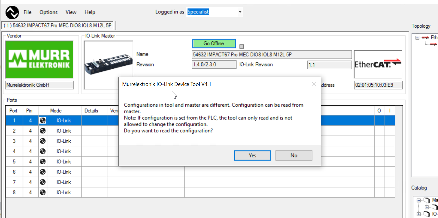
Click on the Go Offline button and connect the IMPACT67 Pro EC DIO8 IOL8 M12L 5P and the tool.
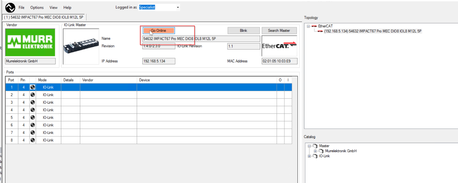
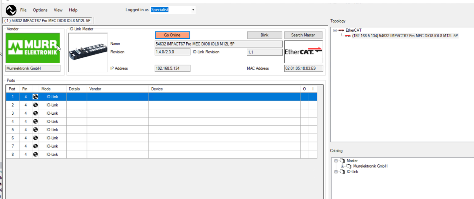
Done!The Go Offline button is now green, which means that Tool and IMPACT67 Pro EC DIO8 IOL8 M12L 5P are connected, click Yes to upload the device configuration from the device.
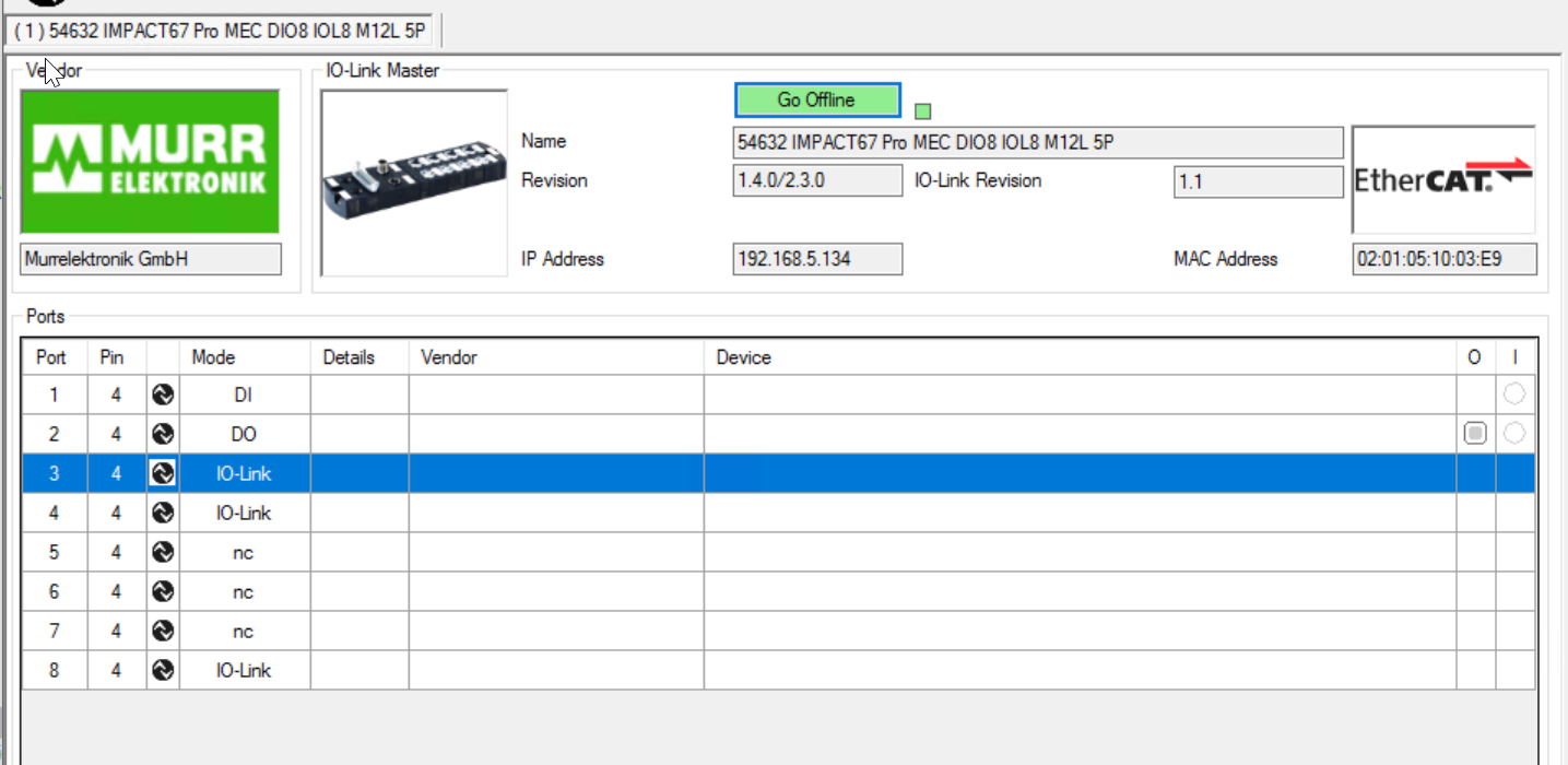
Done!
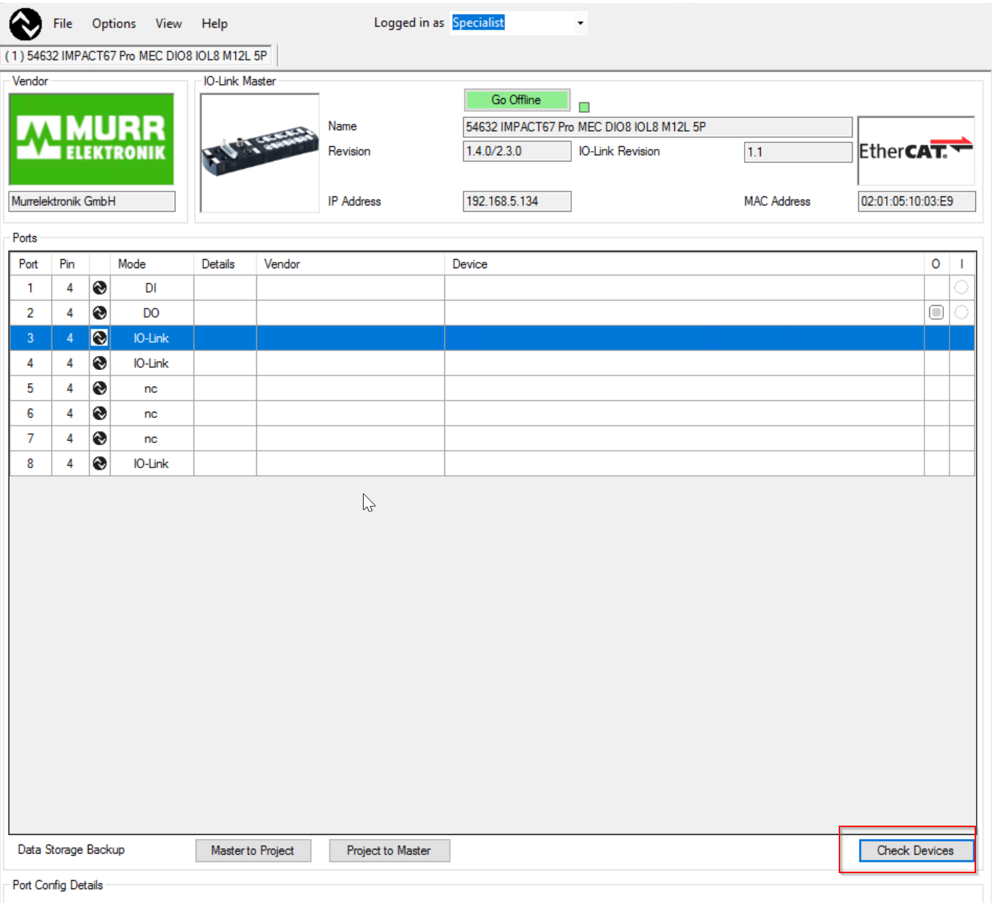
Check Devices
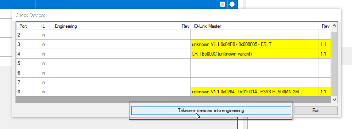
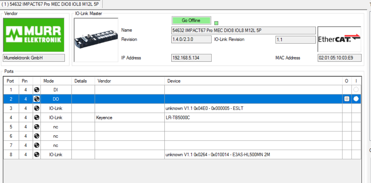
Click the Check Devices button to obtain IO-LINK device information for each port.
Ports marked in yellow are those connected to IO-LINK devices.

Load the information into the project with Takeover devices info engineering.
Done!
Now that the LR-TB5000C IODD File has been imported into the tool, double-click Port4 to see the Port4 information.
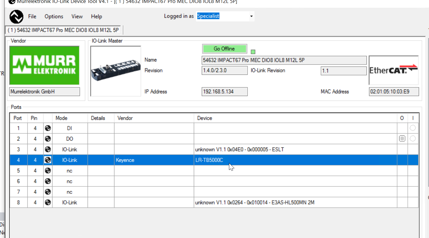
Done!I was able to list information on Keyence’s LR-TB5000C.
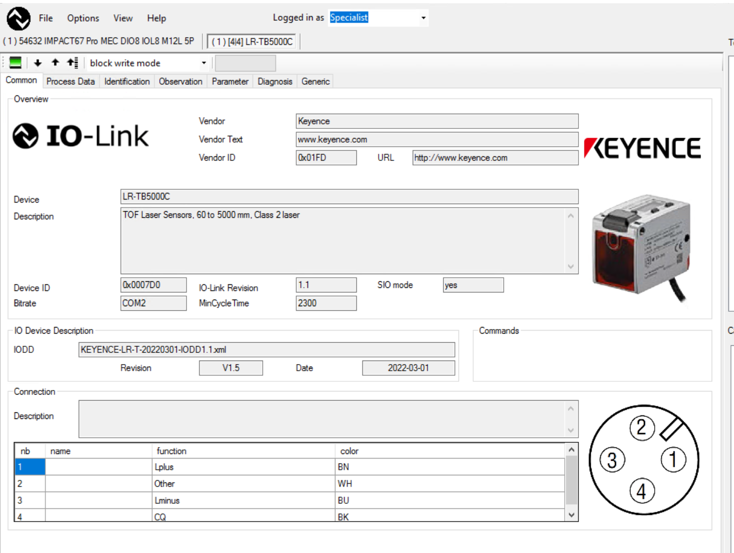
From the Process Data Tab, you can check the Process Data of IO-LINK devices.

From Web
Next, enter the IP address of the IMPACT67 Pro EC DIO8 IOL8 M12L 5P from the Browser to display the Web Server and check information on each port or the module itself.
Of course, you can also configure modules and ports from the Web server, but these operations will be introduced in the next article.
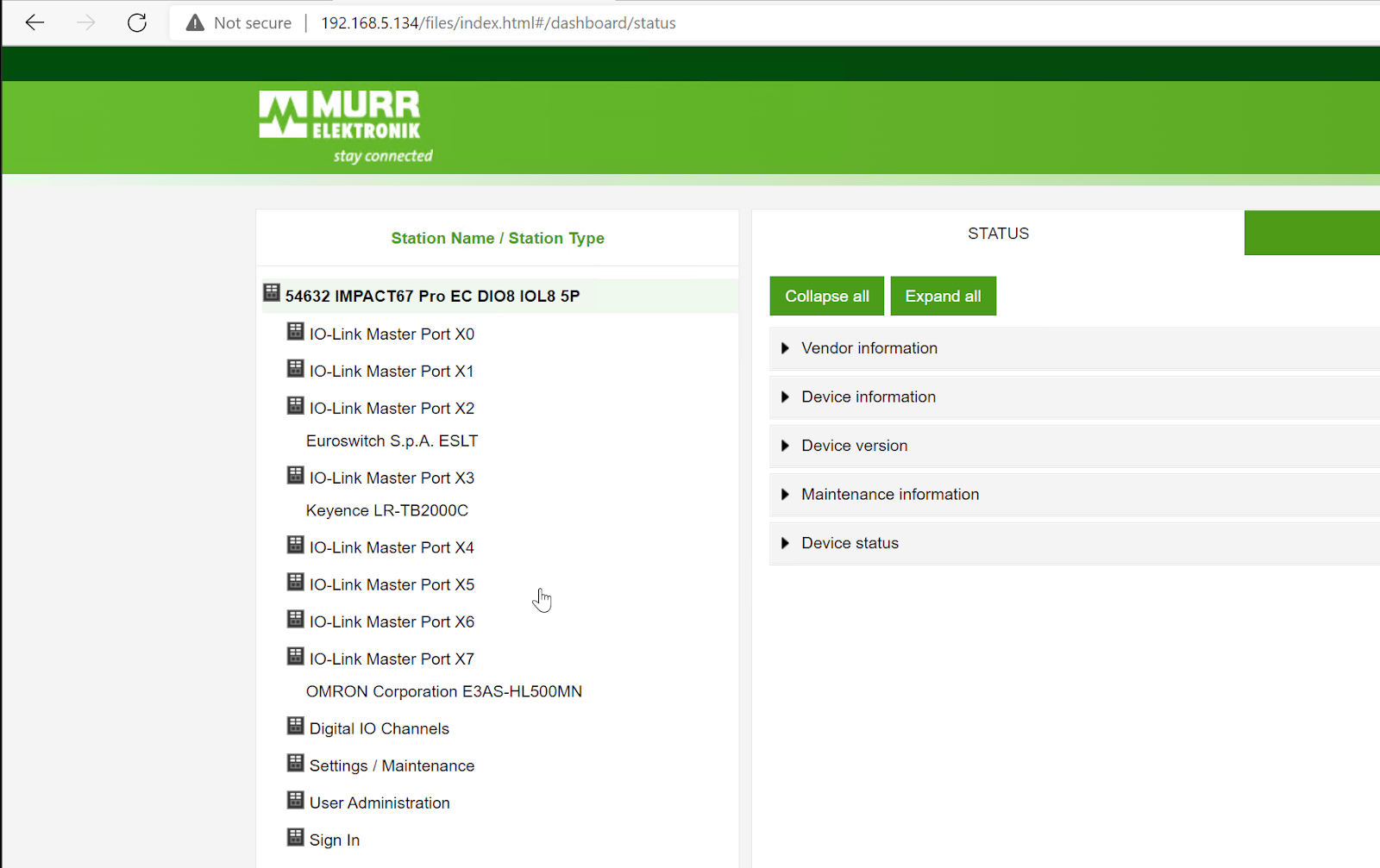
For example, let’s open PortX3.
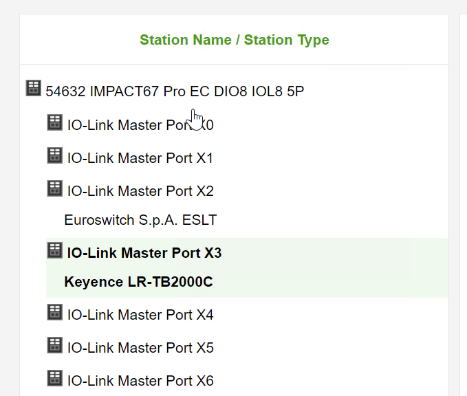
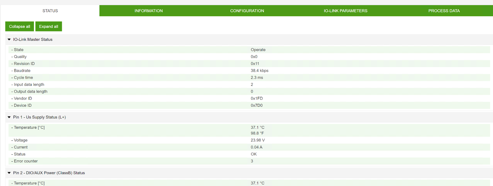
You can check the information of the corresponding Port.
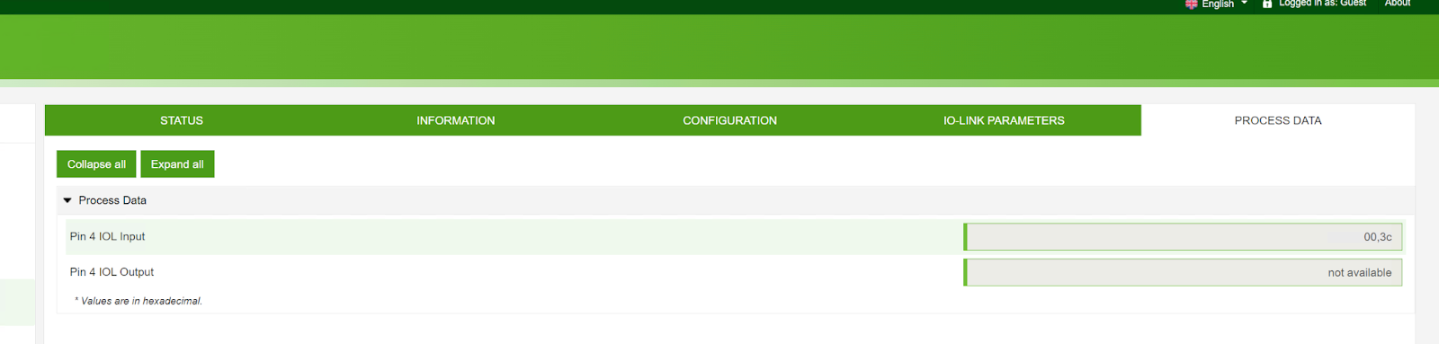
You can check the raw data of the corresponding device with the Tab in PROCESS DATA.
From TwinCAT
Of course, all IO-LINK devices, digital inputs, and digital outputs can also be viewed from the TwinCAT program.
Download
You can download the Sample project for this article from Github here.