This article uses the RD81OPC96 module from Mitsubishi IQ-R, sets up the OPC UA Server and tests the connection from UaExpert and Beckhoff TwinCAT3 TF6100.
In the article, we cover almost all functions of the RD81OPC96.
Now let’s get started!
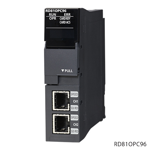
RD81OPC96
By using IQ-R’s RD81OPC96, you can launch the OPC UA Server and access the register data of the IQ-R CPU via this module from other companies’ Clients.
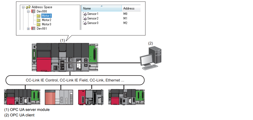
OPC UA Server Functions
The Server function allows OPC UA clients to access tags (devices in the CPU module of their own station and CPU modules on the network) and structure labels registered in the address space set by the configuration tool.
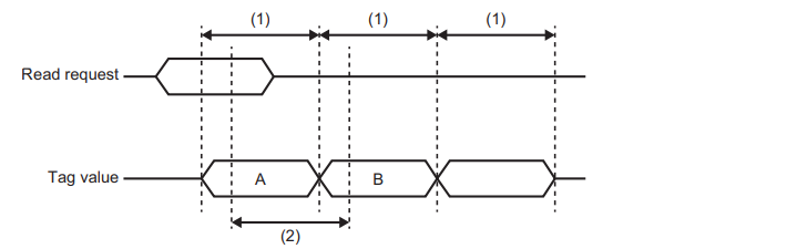
Timing to read data in an OPC UA client
When the OPC UA Client requests to read a tag value in the address space, the tag value at the time when the communication time and OPC UA processing time have elapsed from the request timing is read.
TagA is a Read request sent by an OPC UA Client.
TagB notifies OPC UA Client.
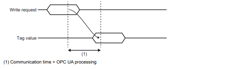
Timing to write data from an OPC UA client (Write)
When an OPC UA client requests to write a tagValue in the address space, the tagValue is written after the communication time and OPC UA processing time have elapsed from the request timing.
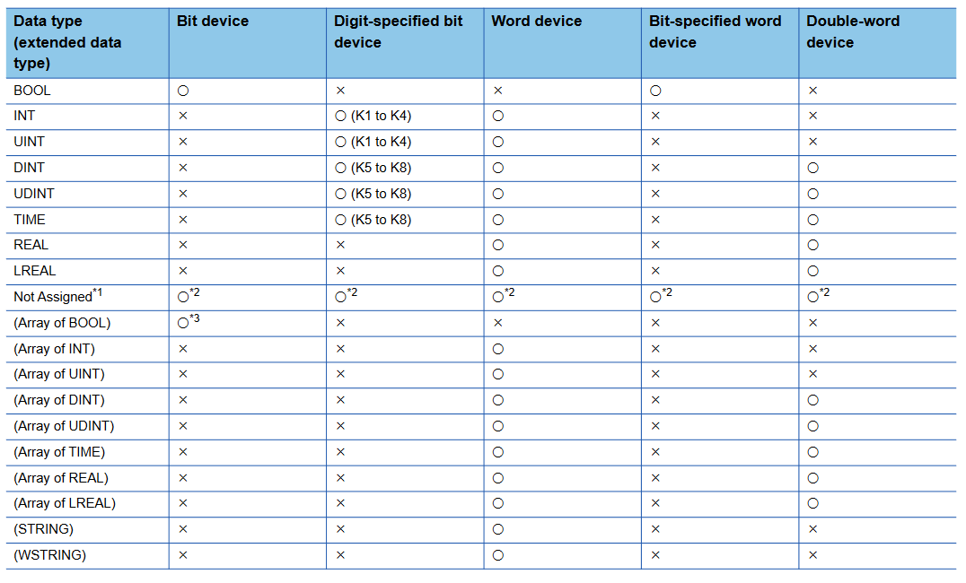
Data Types
The RD81OPC96 can support these Data Types.
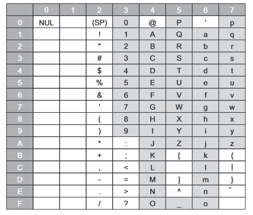
Supprt String
Here is a string that RD81OPC96 can support.
Tool Installation
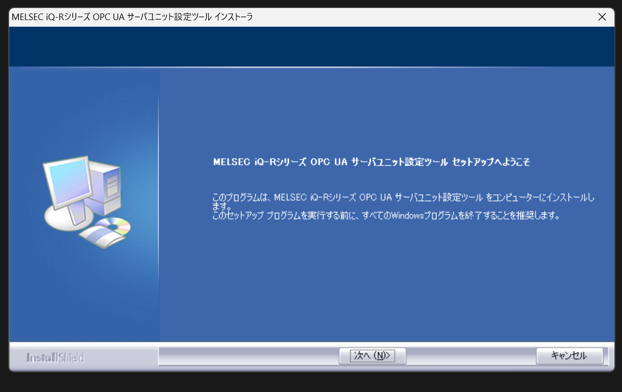
Insert the OPC UA Server unit Setting Tools DVD from Mitsubishi Electric and start the Installation File.
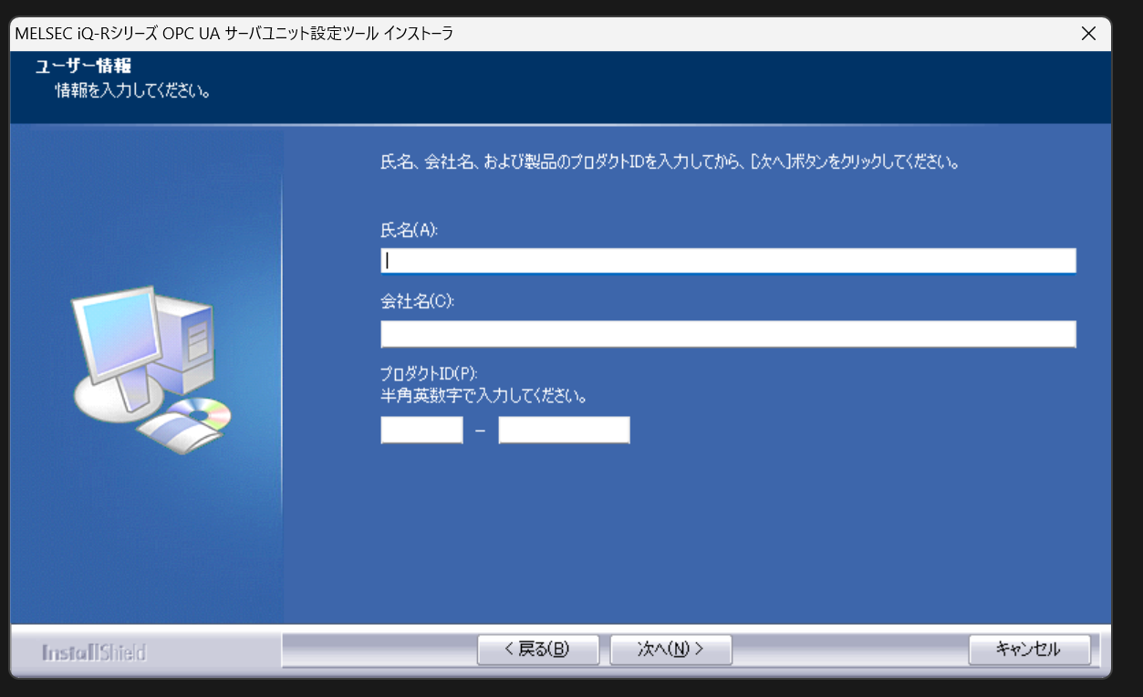
Enter brief personal information and CD-KEY, then proceed.
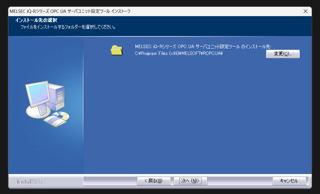
Set the installation path for the tool and proceed.
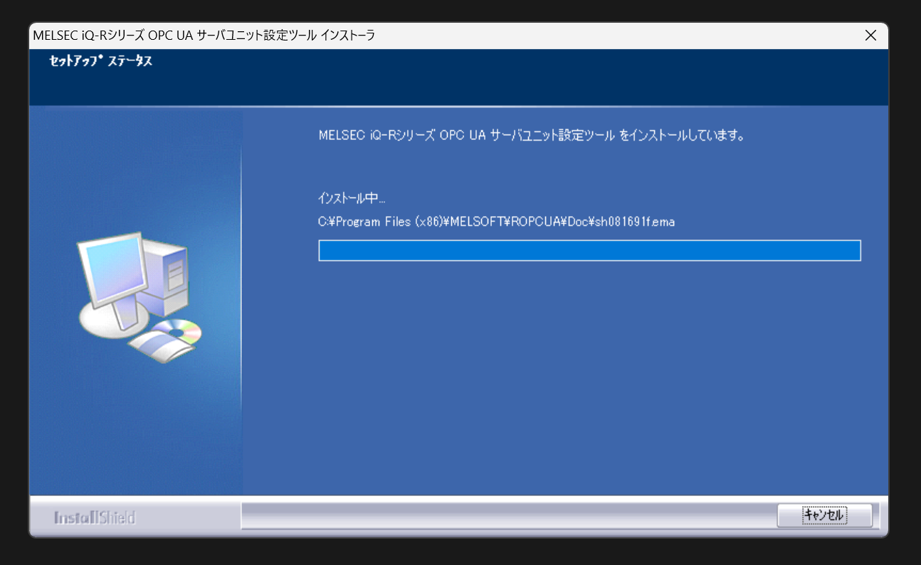
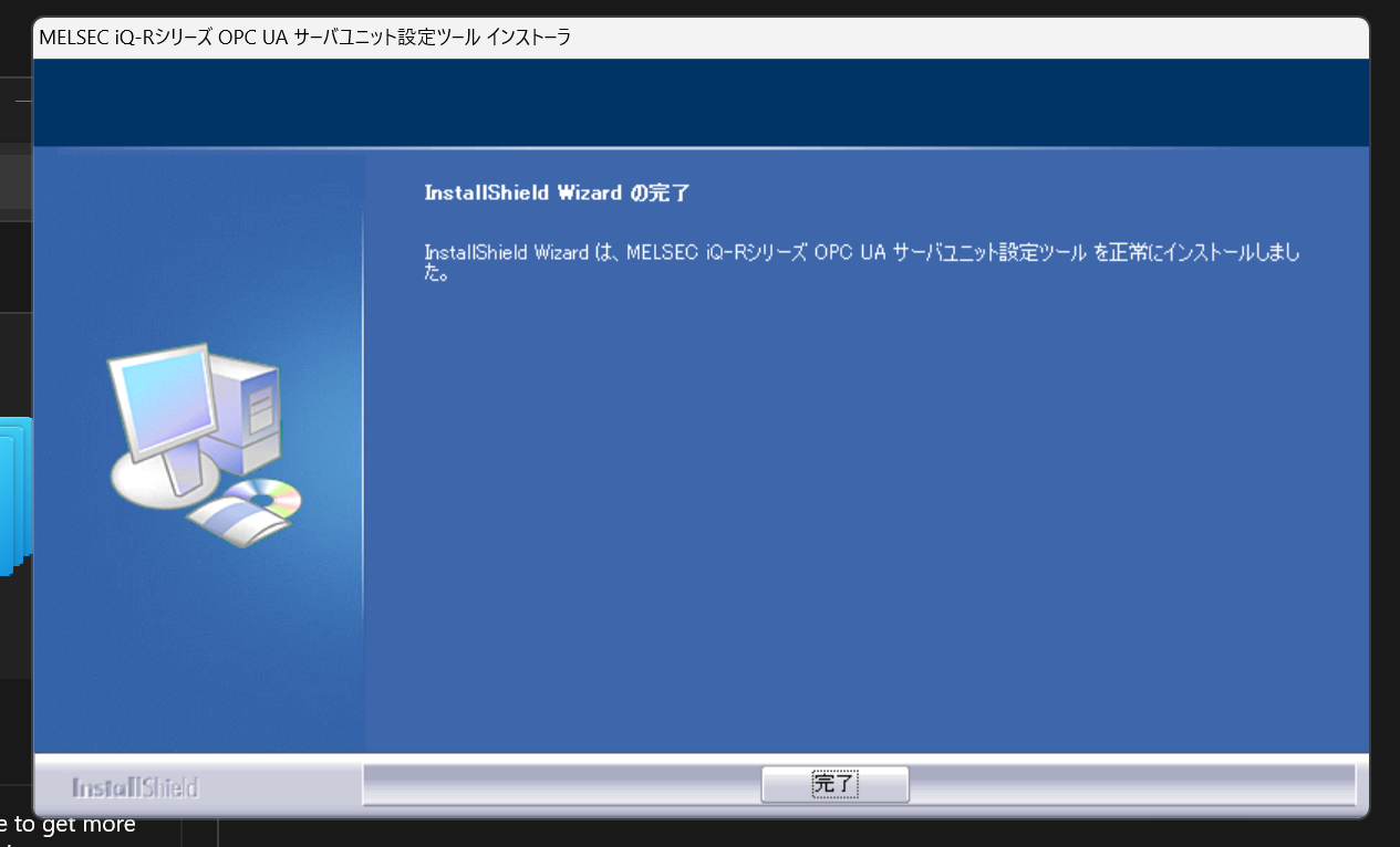
Start installation.
Just a second..
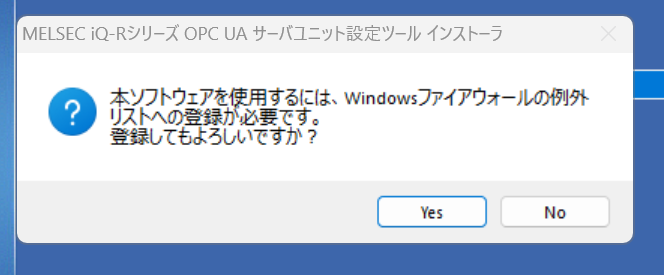
Register an exception list with the Firewall.
The next step is to create a Short-Cut.
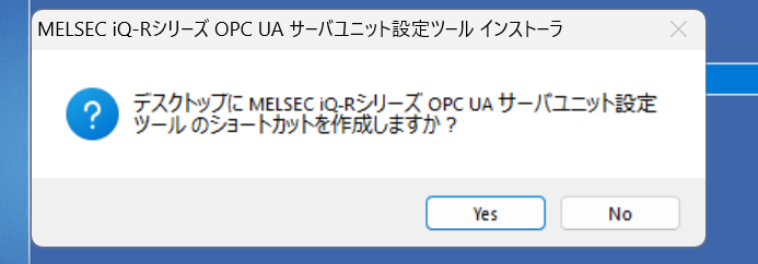
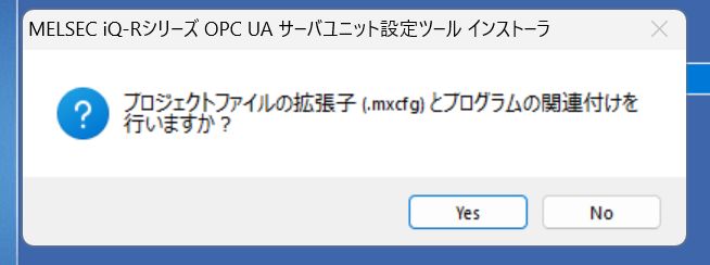
Proceed with Yes.
Done!
Implementation1-Write Single Tag
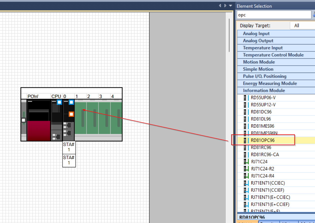
Add Module Configuration
Let’s add the module RD81OPC96 to be used this time in Module Configuration.
Tools
Next, start the MxOpcUaModuleConfiguratorR software.
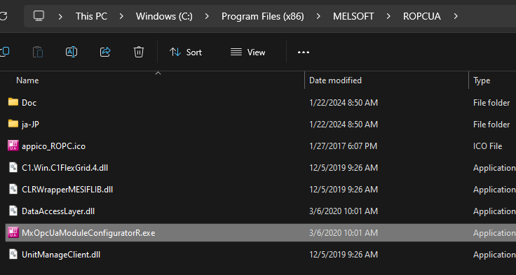
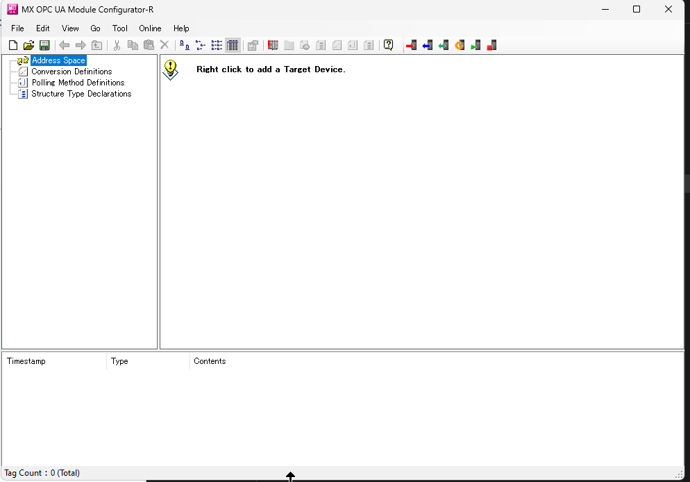
Done!The tool has been activated.
Network Settings
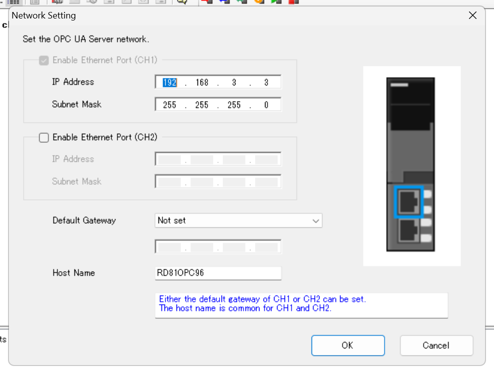
Connect the module to the PC with a LAN cable, and click Tool>Network Setting to set the IP address and other settings for the module.
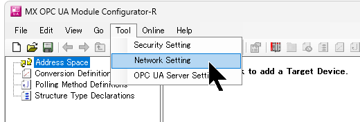
Set the IP address and Host name of the module.
OPC UA Server Setting
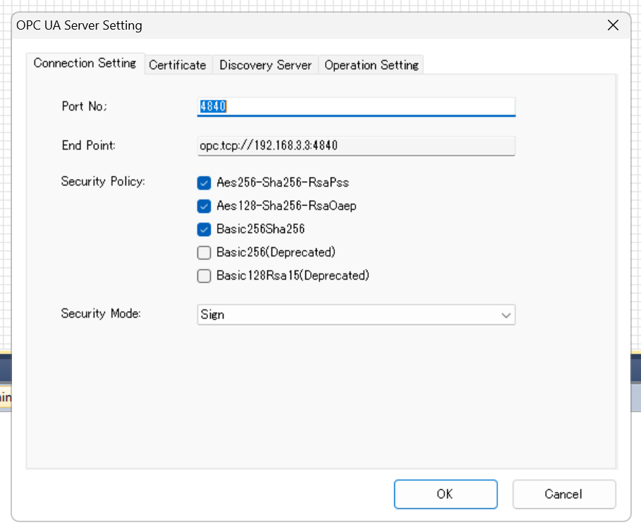
Click “OPC UA Server Setting” to configure OPC UA server settings for RD81OPC96 module.
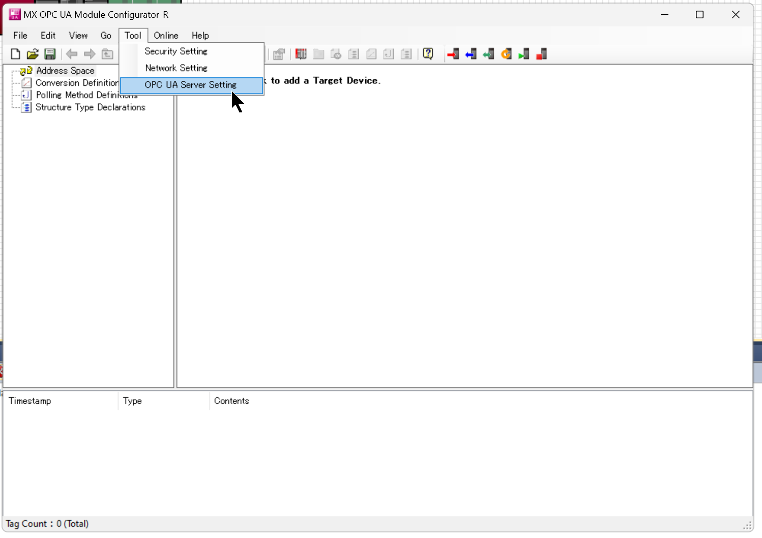
Set the Port number and Security Policy/Mode to match your application.
Security Setting
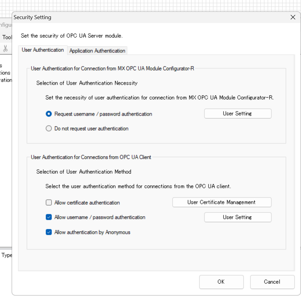
Finally, open the Security Setting to configure security-related settings.
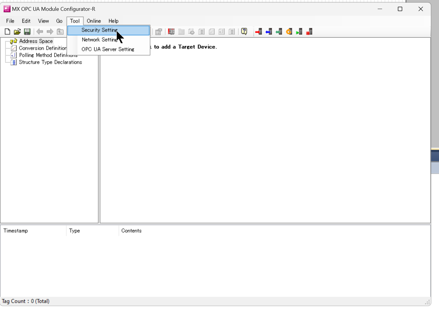
Set security settings, such as requiring a User Name and Password request, according to your application.
Add New Target Device
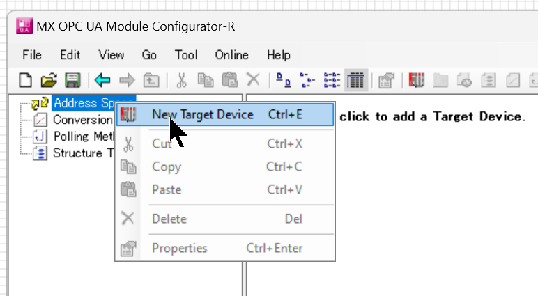
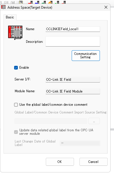
OPC UA manages Tags and Groups in Address Space, so add a new Address Space with Address Space>New Target Device.
The Address Space setting screen appears.
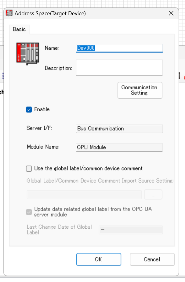
Set Address Space to MyDev000, check the Enable checkbox and press Ok to complete the configuration.
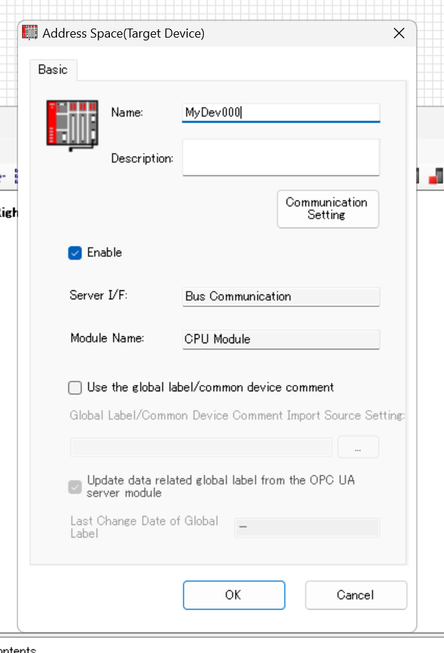
Done!新しいAddress Spaceを作成しました。
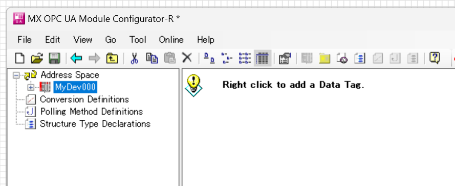
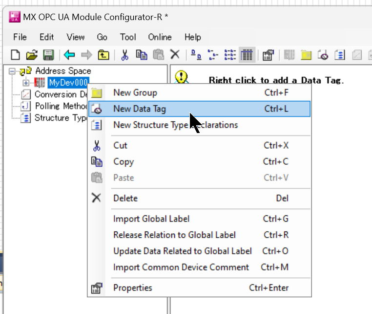
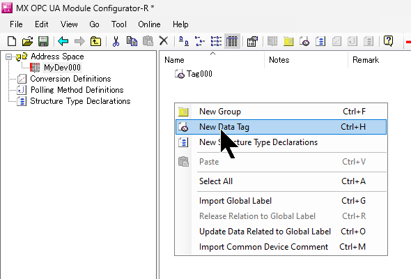
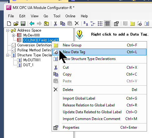
Add New Data Tag
To add a Tag to the Address Space you just added, click Address Space>right click>New Data Tag.
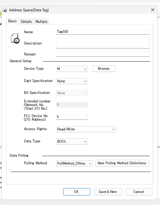
The Tag setting screen appears.
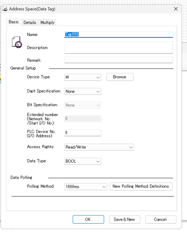
Device Type
Device Type corresponds to the device type such as D or M inside the IQ-R CPU.
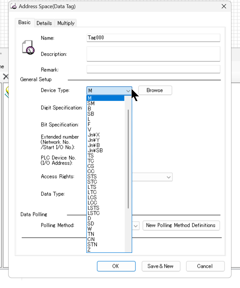
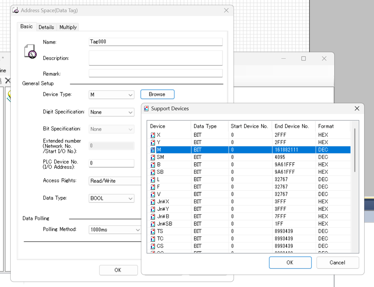
Click on the Browse button to see a list of devices that the RD81OPC96 module can support.
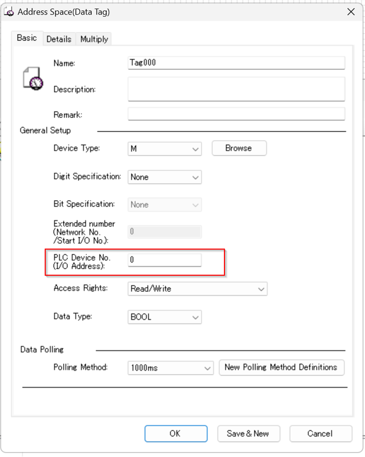
PLC Device No(I/O Address)
Here you can specify the device number of the IQ-R CPU. In this Example, it is tied to M0 of IQ-R.
Finally
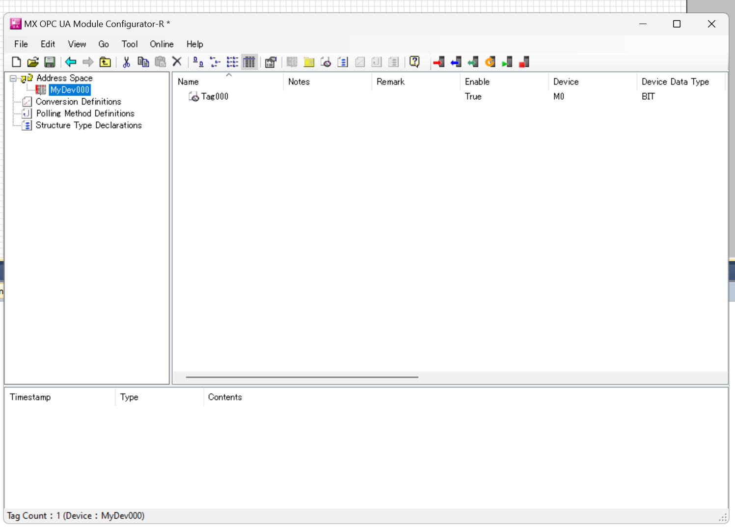
Done!Added Tag for the first time.
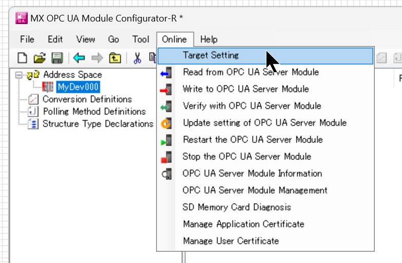
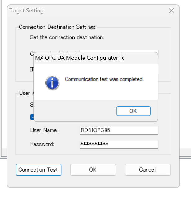
Target Setting
To Download the project to RD81OPC96, open Target Setting and perform a communication test.
This is the setting screen for communication settings.
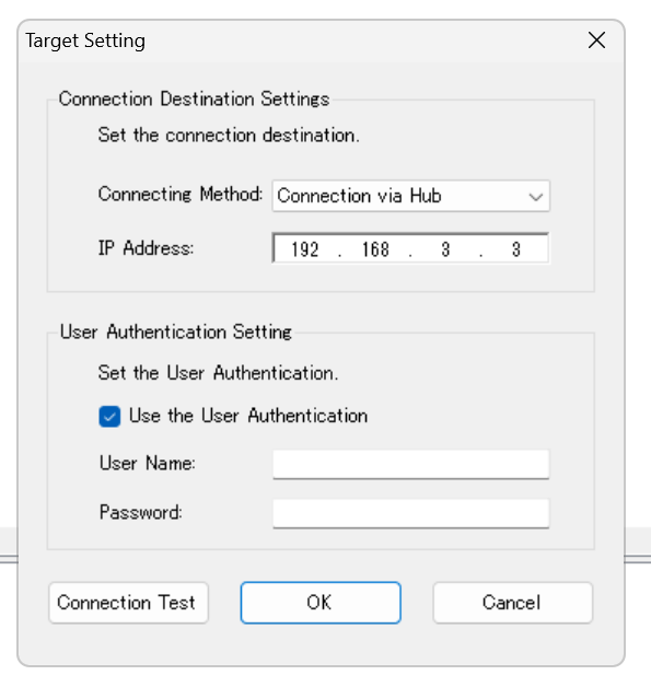
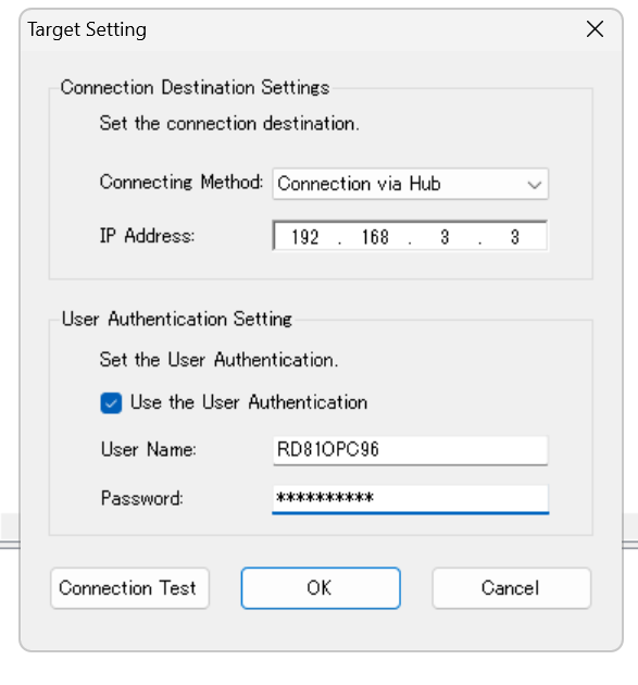
The Default IP address of RD81OPC96 is 192.168.3.3, Username is RD81OPC96 and Password is MITSUBISHI.
Click the Connection Test button to test communication with RD81OPC96.
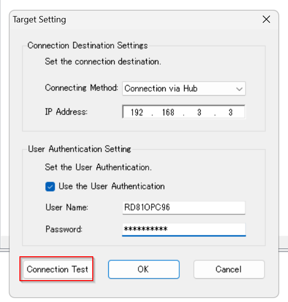
Done!
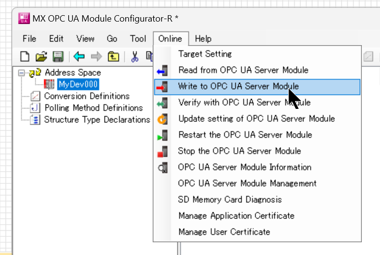
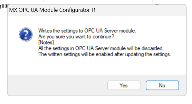
Write to OPC UA Server Module
Online>Write to OPC UA Server ModuleでConfigurationをRD81OPC96にDownloadしましょう。
Proceed with Yes.
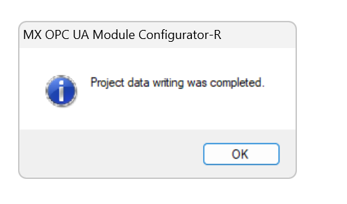
Just wait a second…

Done!
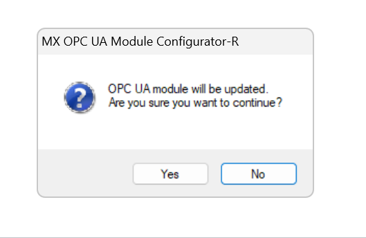
Update OPC UA module RD81OPC96 with Yes.
Result
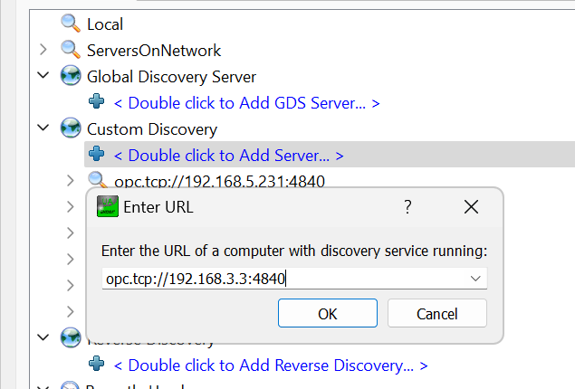
Start UaExpert and enter the following URL to connect to the OPC UA Server in RD81OPC96.
| opc.tcp//yourIP:4840 |
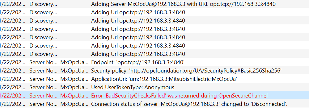
Basic256Sha256-Sign & Encrypt is used in this Example.
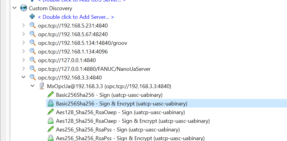
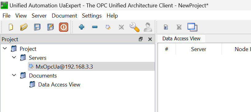
OPC UA Server is added, and let’s connect to RD81OPC96 with the Connect button.
Trust the certificate of RD81OPC96.
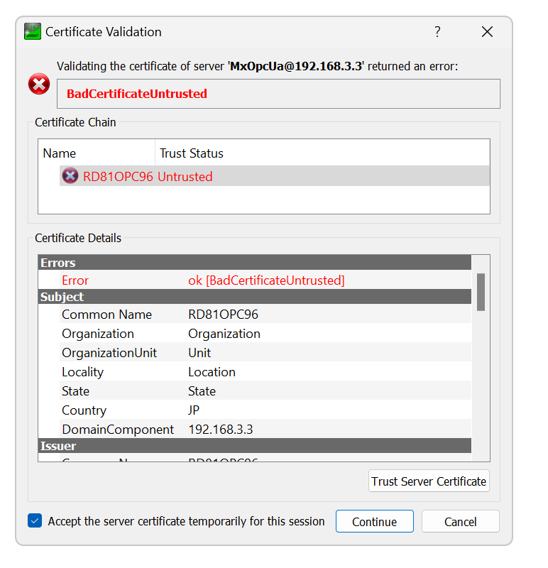
However, I received a “BadSecurityChecksFailed” error from UaExpert.
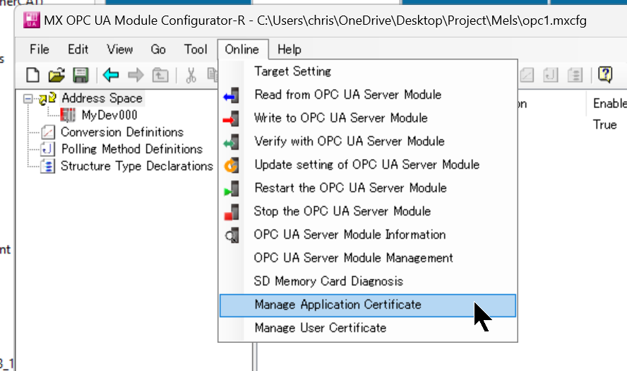
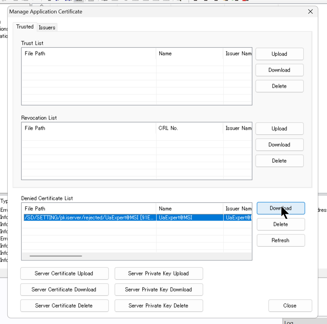
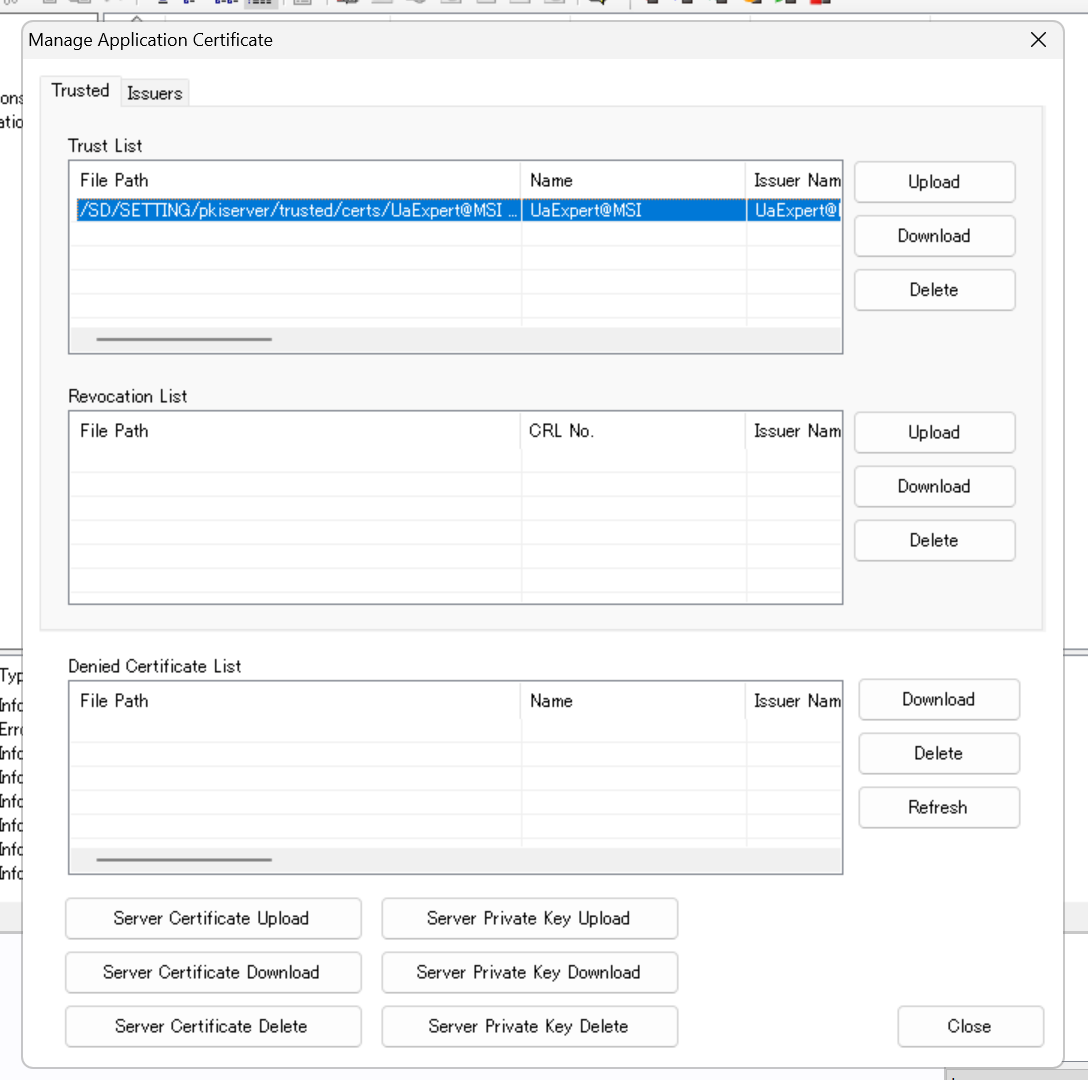
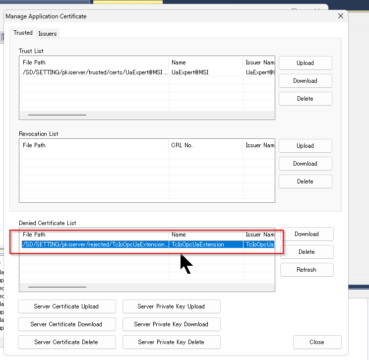
RD81OPC96 must manually manage the certificate, click Online>Manage Application Certificate.
UaExpert’s Certificate is currently on the RD81OPC96 reject list.
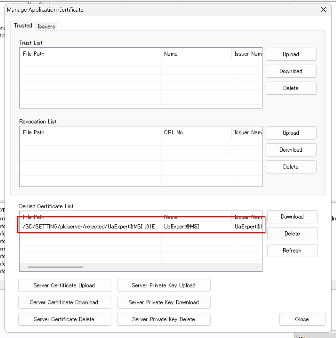
Download the UaExpert certificate once.
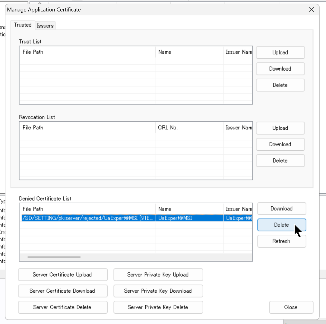
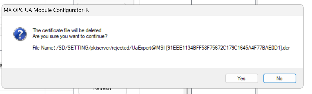
Delete the UaExpert certificate.
Proceed with Yes.
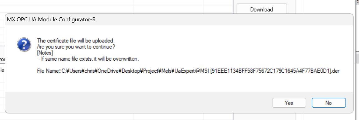
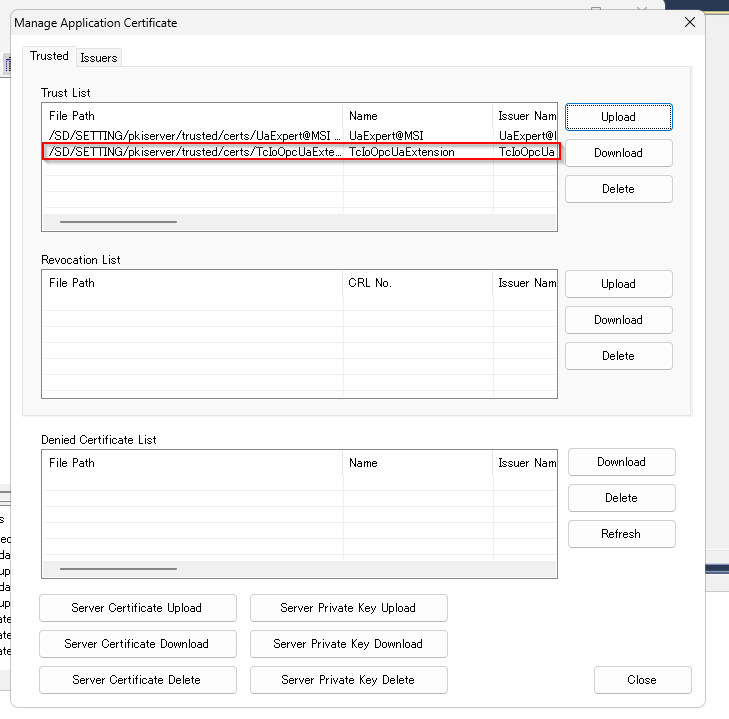
Now click the Upload button at the Trust List and transfer the certificate you have just downloaded to RD81OPC96.
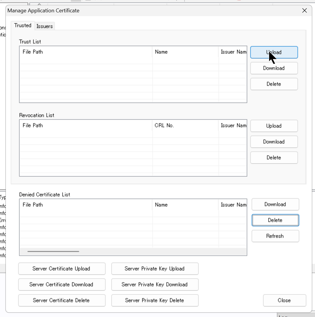
Proceed with Yes.
Done!
UaExpert certificates are now stored on the Trust List.
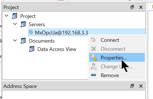
Now click on Properties to change UaExpert’s Login settings.
Enter your Username and Password.
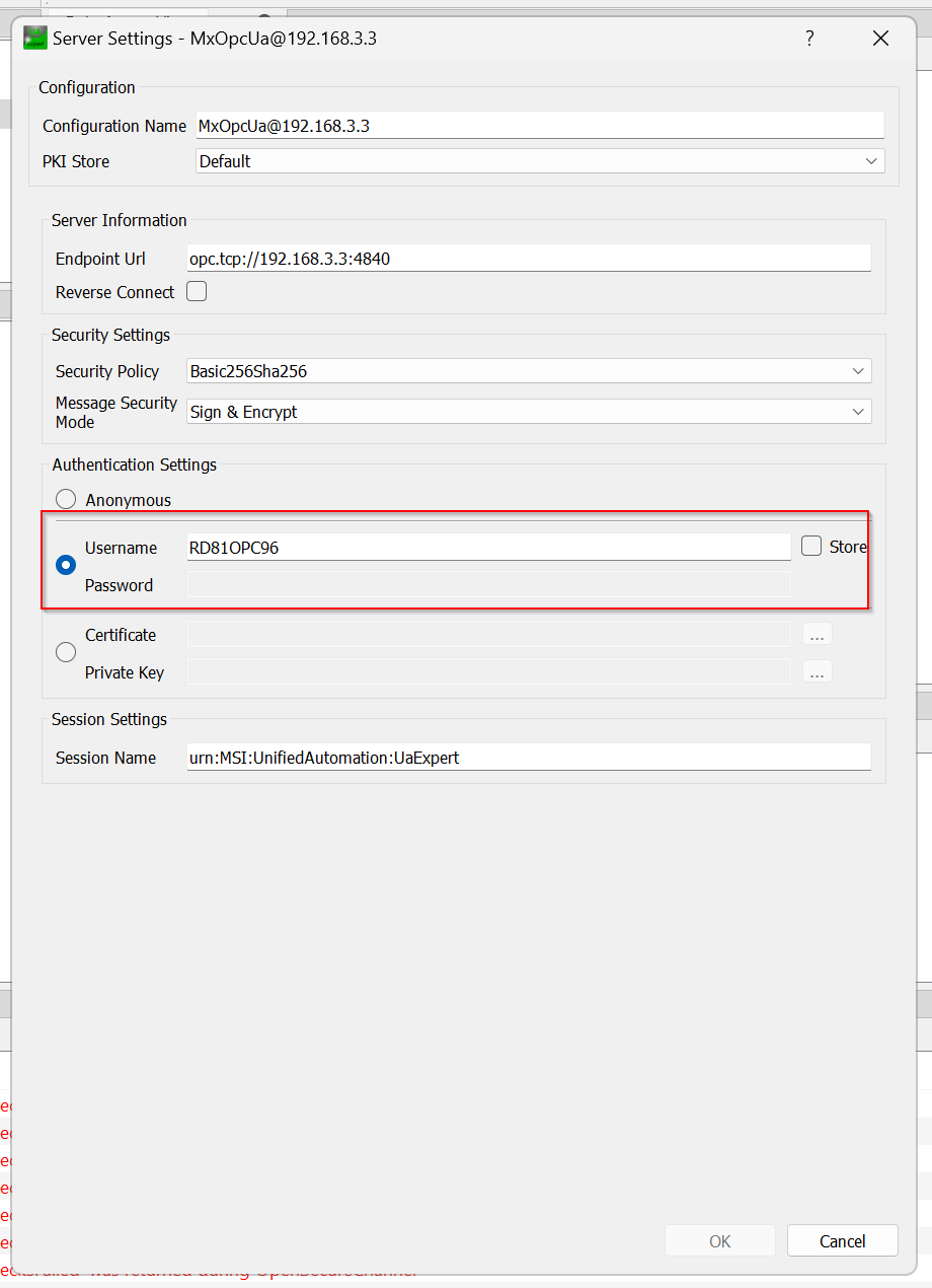
Done!I was able to connect with RD81OPC96.
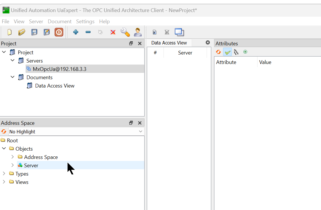
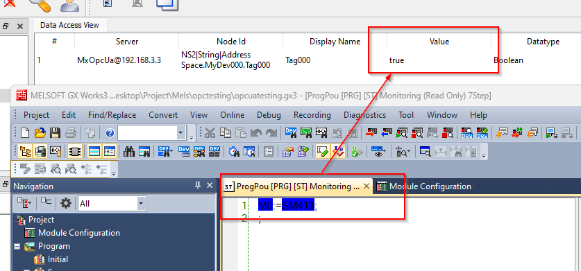
There was a MyDev000 added earlier in the Address Space and a Tag000 inside.
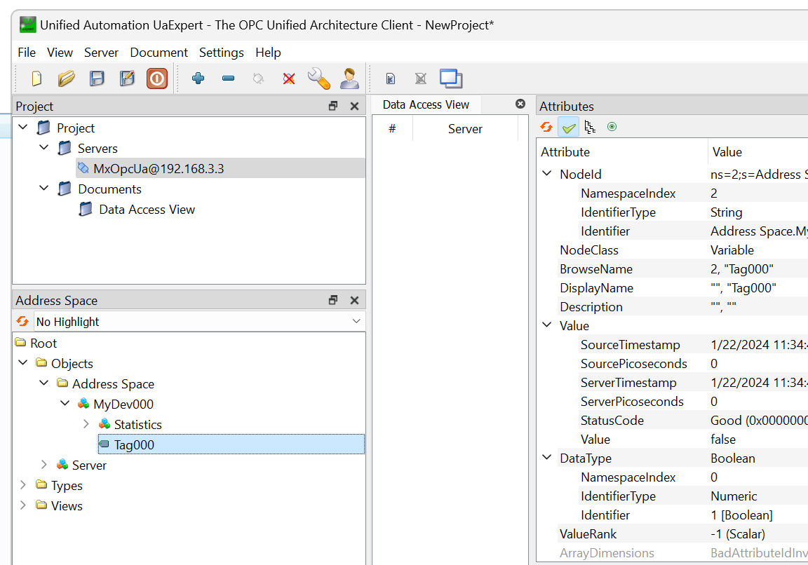
Drop Tag000 into UaExpert.
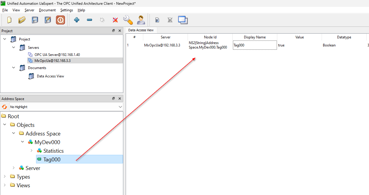
Set GXWORKS3 or M0 to True, I could see the same value from UaExpert.
Implementation2-Digital Specification
In this article, we will show you how to set up multiple Mitsubishi M devices to be grouped together as an OPC UA Node. For example, you can get Mitsubishi devices together in the form of K4M0, K4B0, etc.
Configure Tag
Right click on Address Space MyDev000>New Data Tag.
There is a selection Option called Digit Specification.
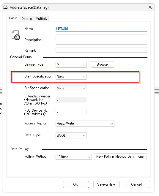
From the Drop-List, you can select 1-8, and None, which treats devices such as M as bit units.
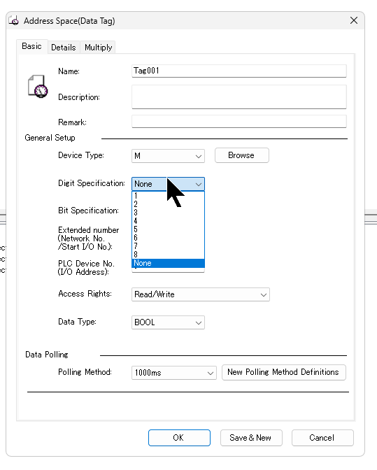
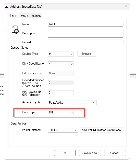
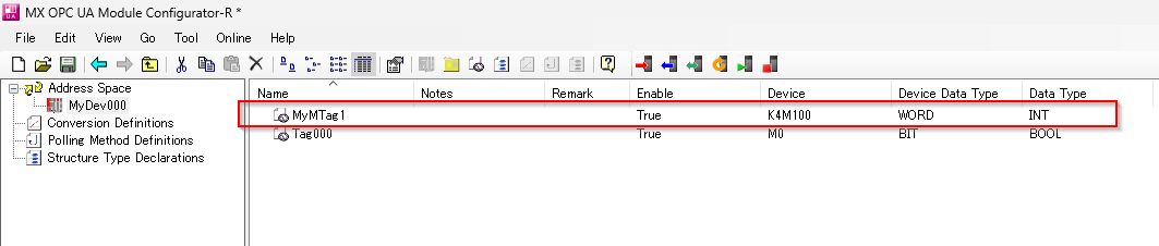
In this article, Digit Specification is set to 4, Tag001 will handle K4MX, and Data Type is set to INT.
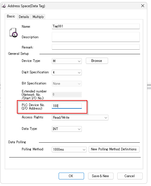
Set the PLC Device No. (I/O Address) to 100. In other words, Tag001 is treated as K4M100.
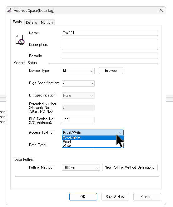
You can set the read/write permissions for the corresponding OPC Node from the Drop-List of Access Rights.
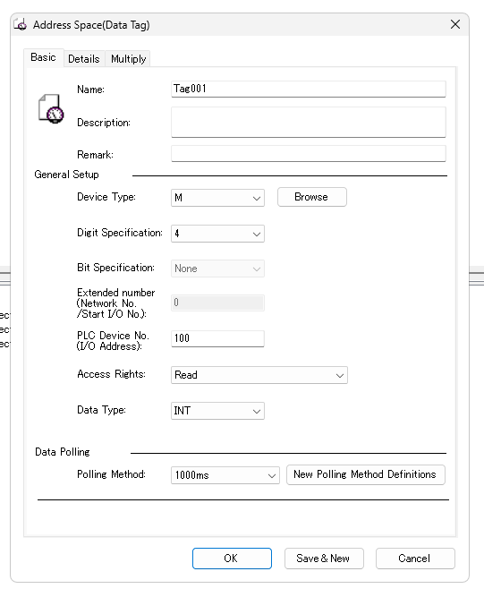
Set Tag001 to Read. In other words, Tag001 becomes a read-only Tag.
Done!
Result
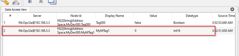
I was able to access the MyMTag1 I just added from UaExpert.
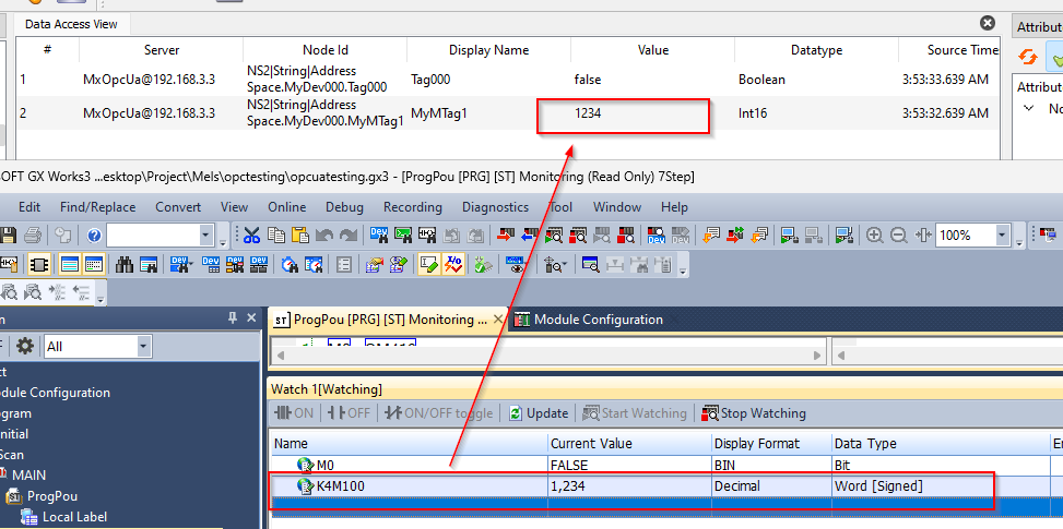
K4M100 from GXWORKS3 to 1234. we could see the same value from UaExpert.
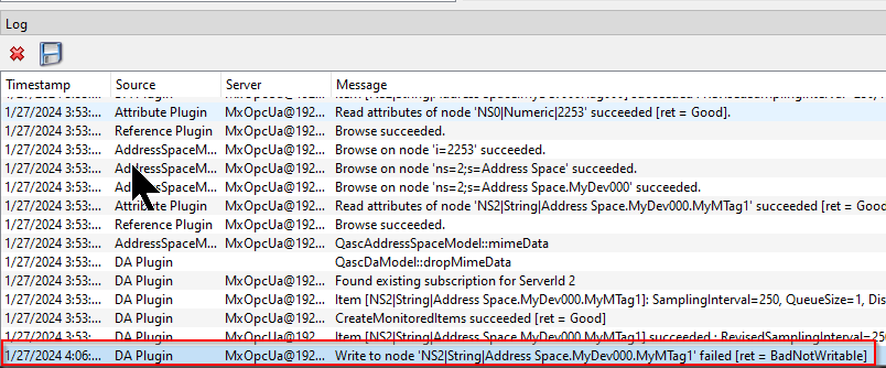
However, when I tried to change the current value of MyMTag1 from UaExpert, I got a BadNotWriteable error Feedback.
This is because I just set MyMTag1 to Read only.
Implementation3-Group Configuration
Next, we define a Group in Address Space MyDev000, which allows us to combine multiple Nodes into a single “Folder”.
Configure Group
Select Address Space MyDev000>right click>click New Group.
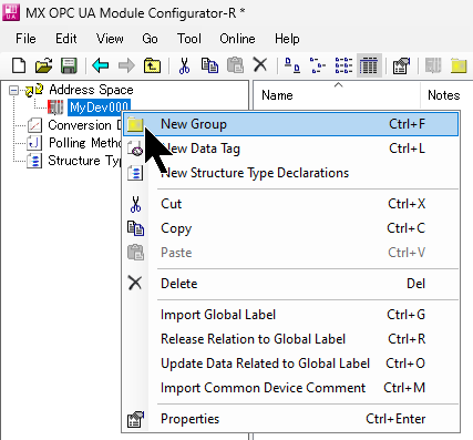
Enter the Group name.
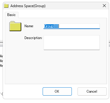
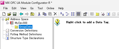
Done!A new Group has been added.
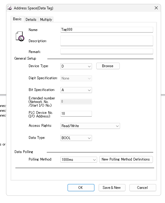
In this case, the D register is accessed, but by specifying the Bit Specification, certain bits of the Data register, such as D, can be accessed.
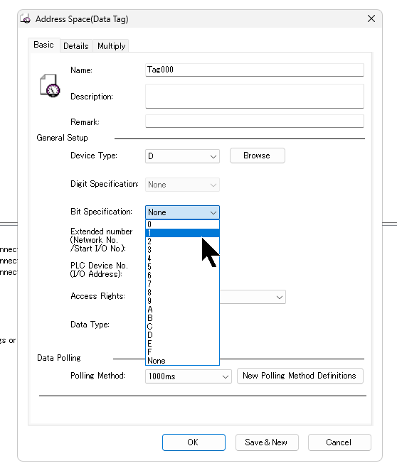
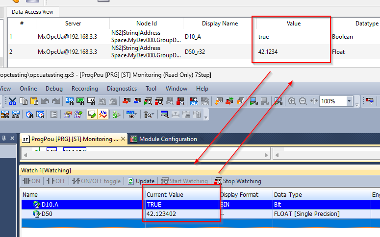
The following configuration will result in an OPC UA Node accessing D10.A.
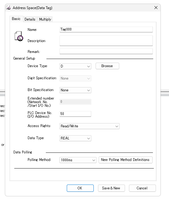
Let’s set up Tag000 to access the real number with another D50.
Done!
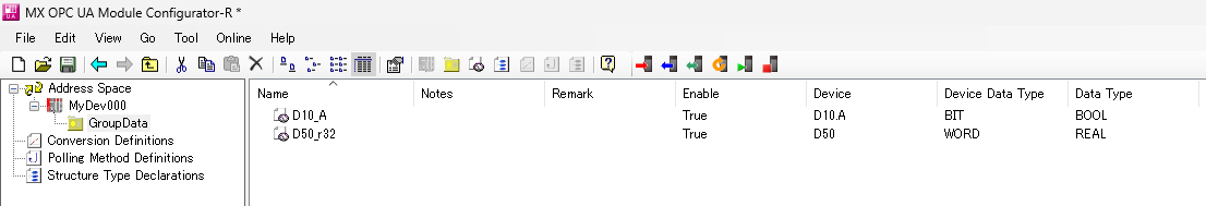
Result
I was able to retrieve the D10_A and D50_r32 Nodes I defined earlier from UaExpert.
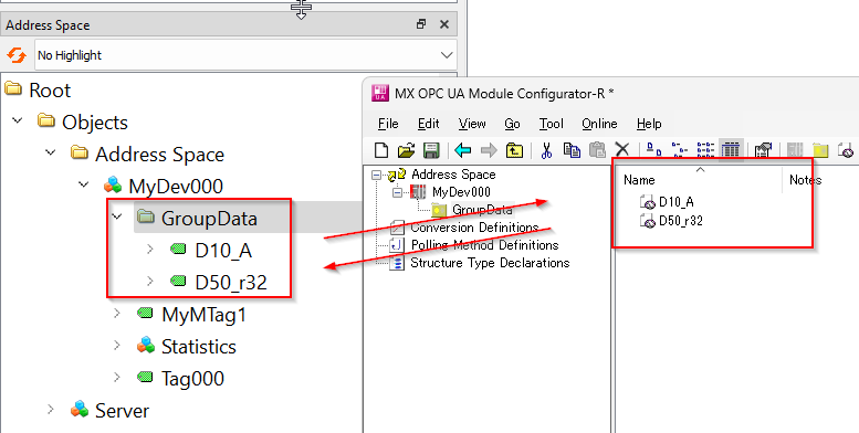
When I changed the current values of D10.A and D50 from GXWORKS3, I could see the same values from UaExpert.
Implementation4-Configure Structure Type
Now define the structure in the project and create a variable for the structure in Address Space MyDev000.
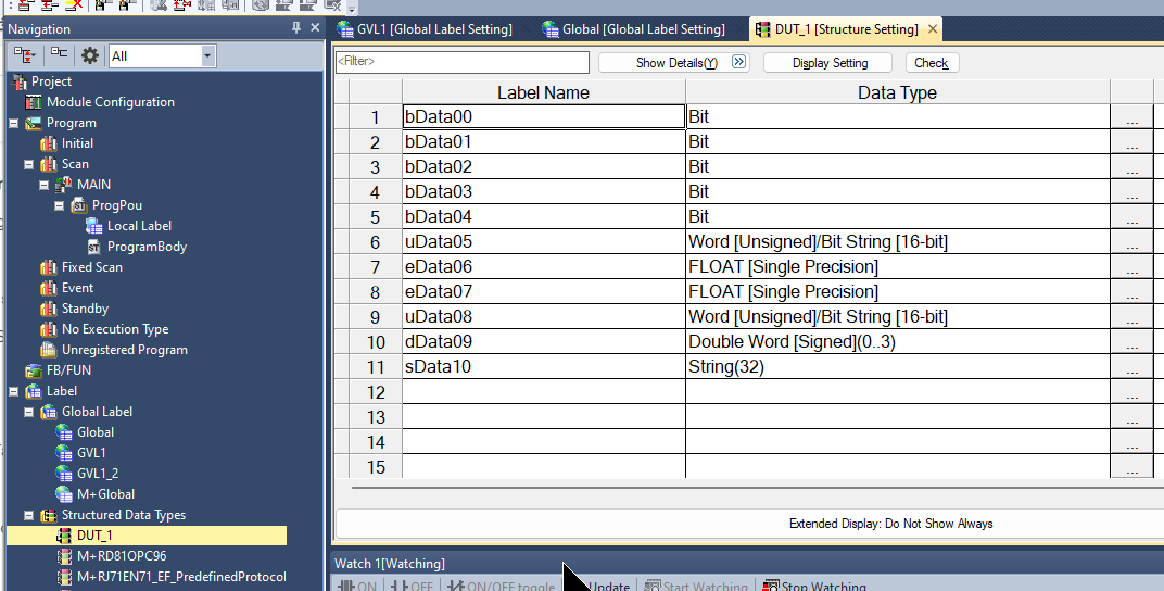
Configure Structure Type
Click on Structure Type Declarations to define the structure.
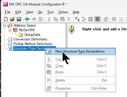
The screen changes to the structure creation screen.
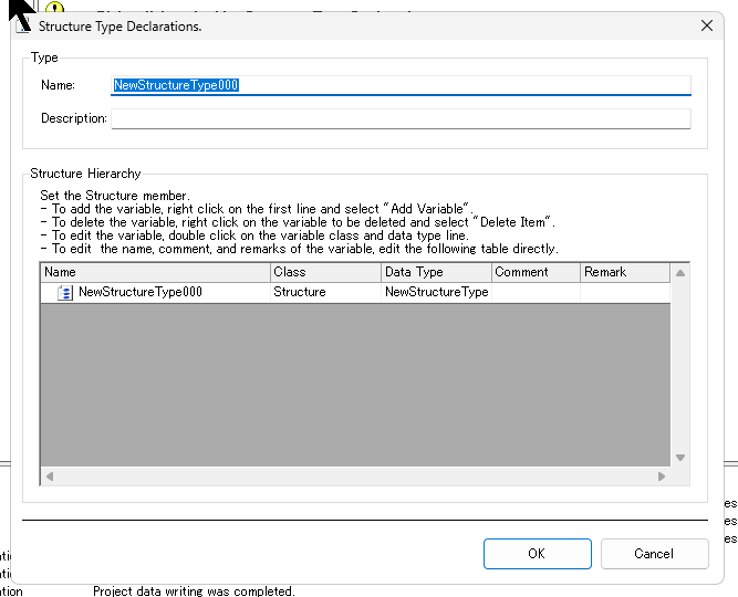
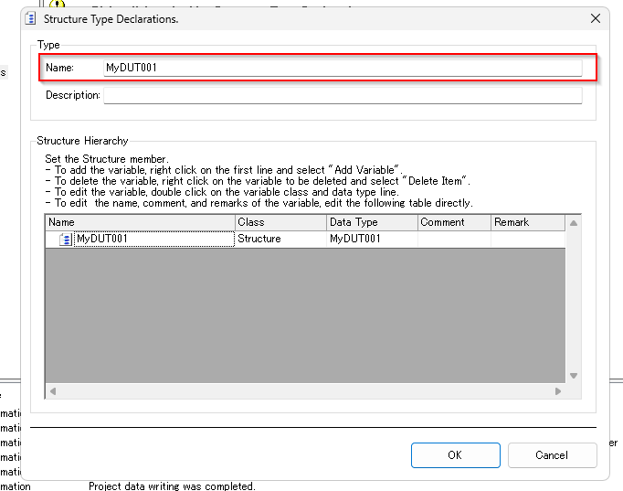
Enter the name of the structure in the Name Field.
Right-click on the gray area>Add Variable to add a structure Element.
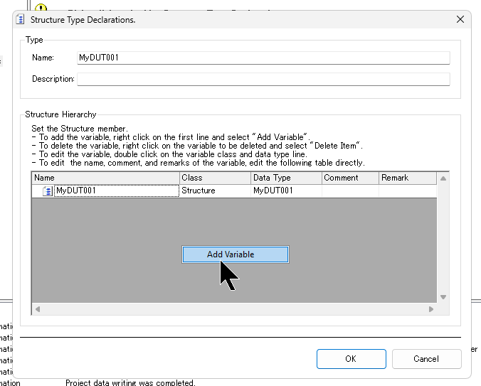
The Add Variable screen appears.
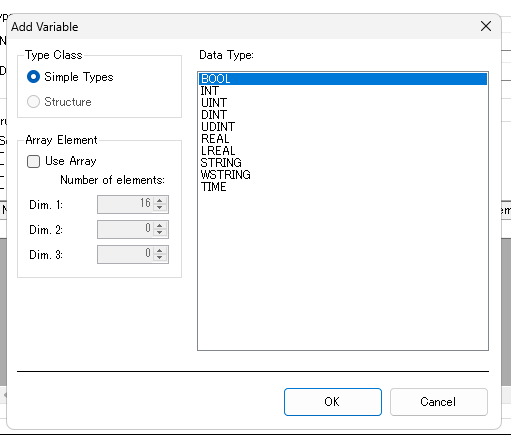
Create the structure according to your application.
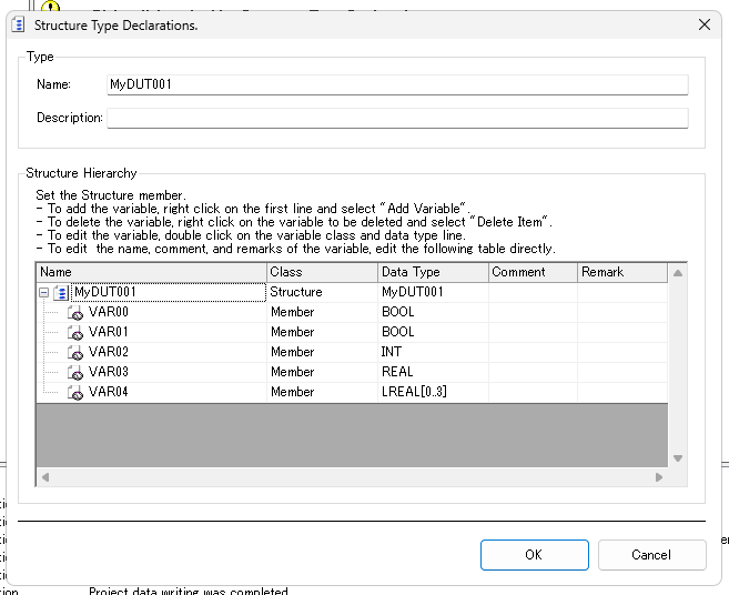
Done!DUT is created.
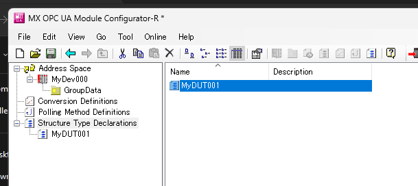
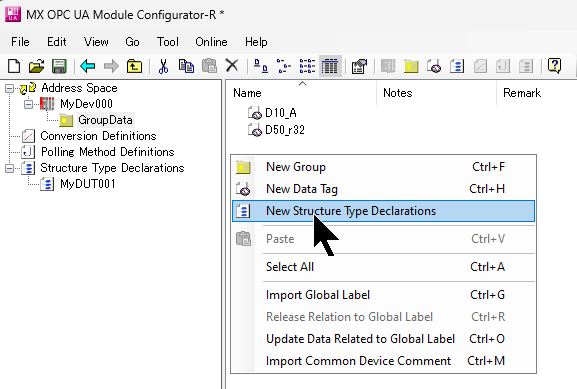
Add New Structure Variable
Next, let’s declare a new structure variable in Address Space MyDev000 under GroupData>Right click>New Structure Type Declarations.
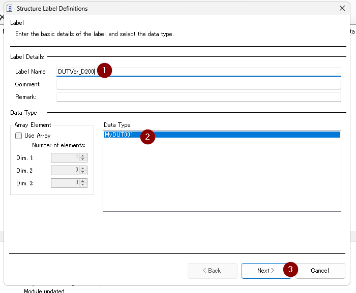
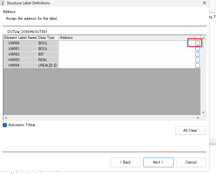
The structure variable declaration screen is now displayed.
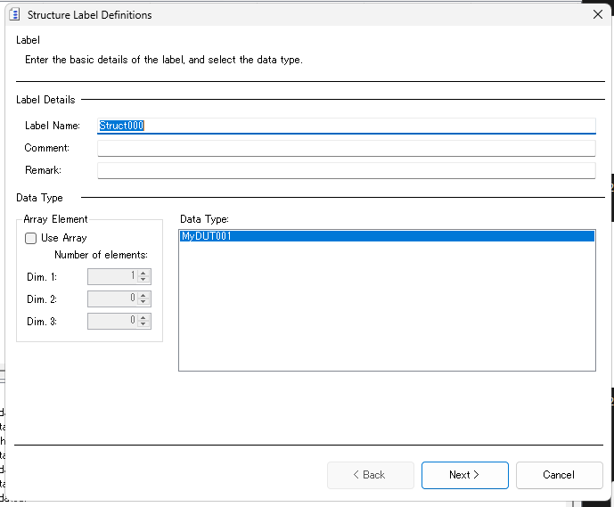
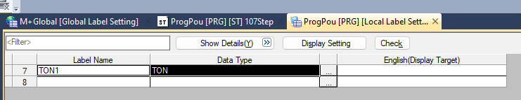
Set the structure variable name in Label Name and select the structure you have just declared from the List of Data Type.
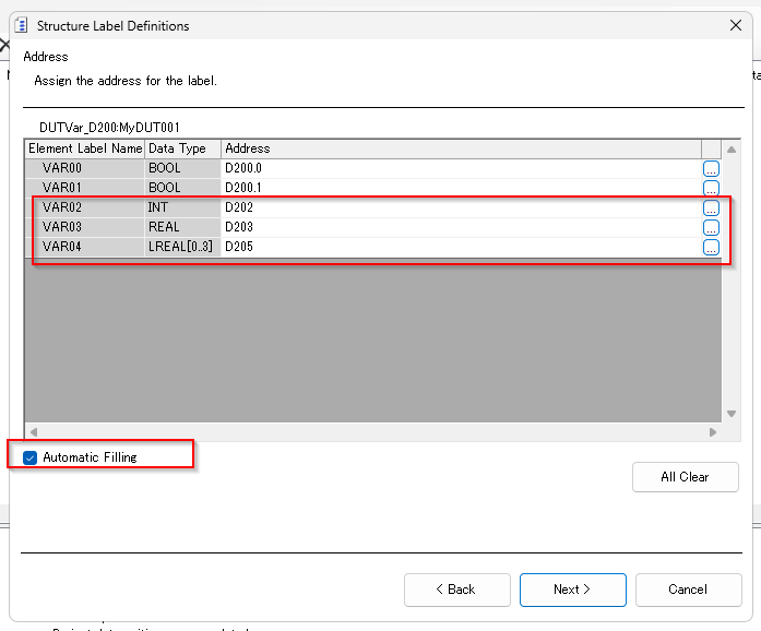
The next step is to set the absolute address of each component in the structure.
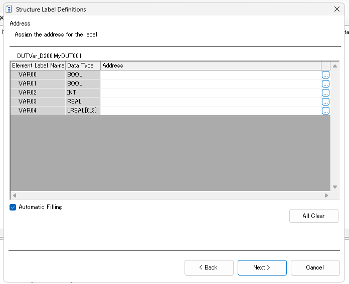
Press the … button to set the address.
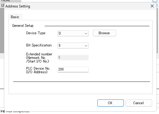
This is the Address Setting screen.
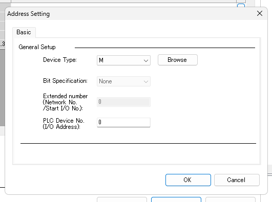
In the diagram below, D200 is set.
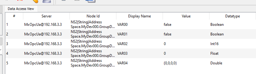
Done!VAR00 and VAR01 correspond to D200.0 and D200.1 of the IQ-R CPU.
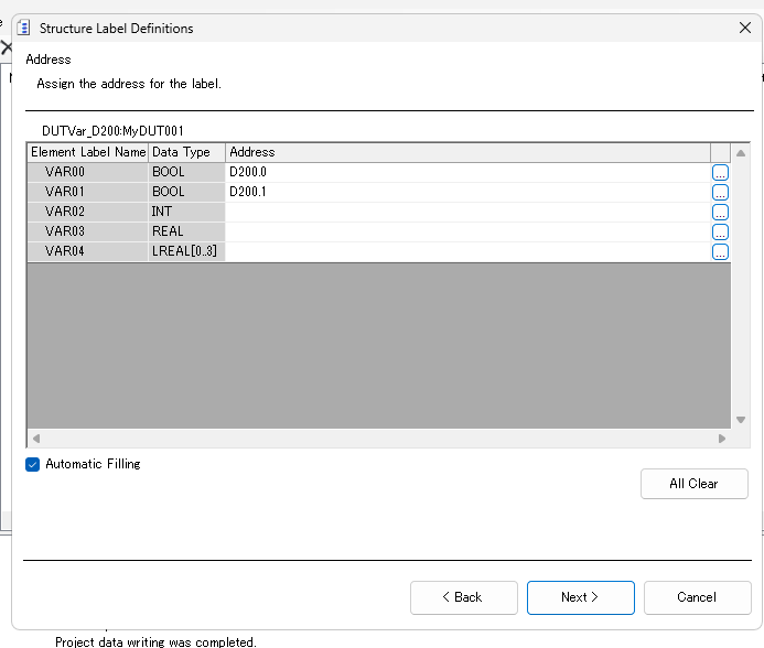
Finally, if you put in the Automatic Filling Checkbox and VAR2 enters D202, the tool will automatically set VAR03 and VAR04 to D203 and D205 as well.
The final step is to set permissions for reading, writing, etc.
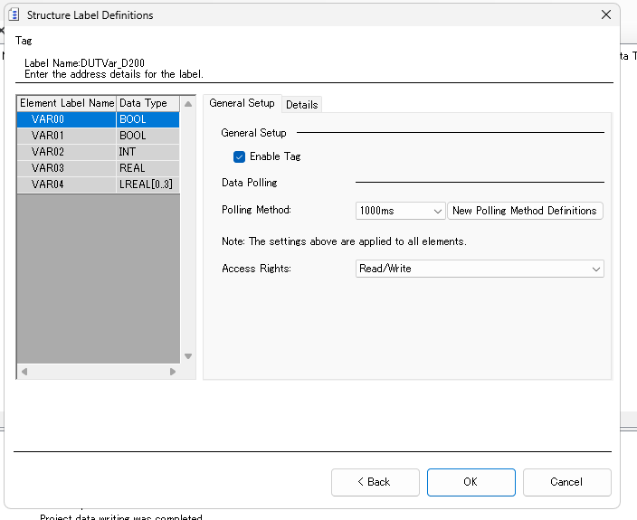
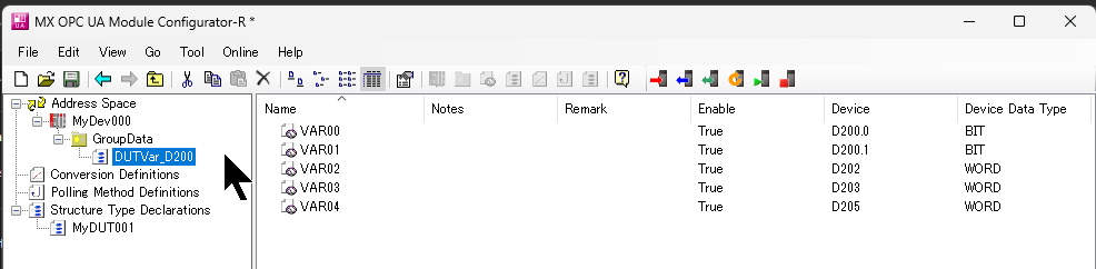
Done!
Result
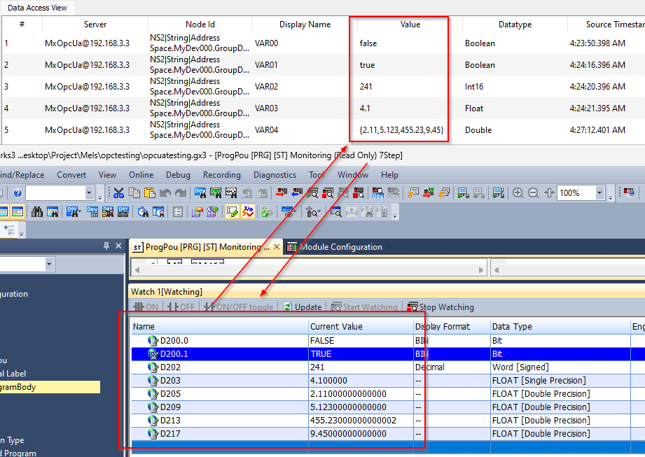
The DUTVAR_D200 Node declared earlier from UaExpert could be retrieved!
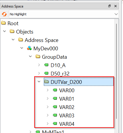
Changes to register values from D200 are reflected in UaExpert in the same way.
Implementation5-Polling Method/Convert Function
Add Polling Method
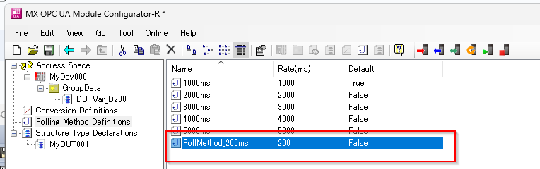
Polling Method can define the Node update period and method, and RD81OPC86 can be set to a minimum of 200 ms.
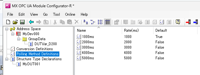
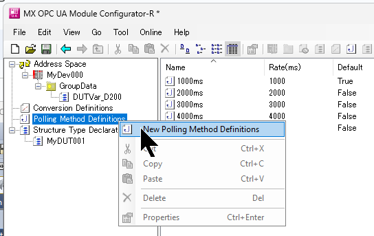
To define a new Polling cycle, click Polling Method Definitions>New Polling Method Definitions.
The Polling Method definition screen is displayed.
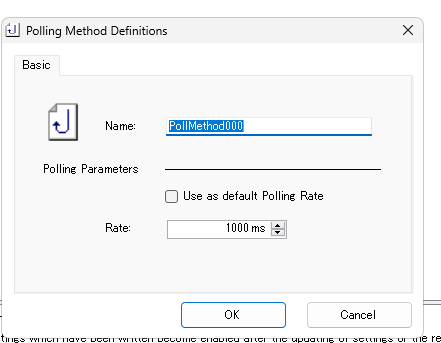
Rate allows the update period to be set, this time to 200 ms.
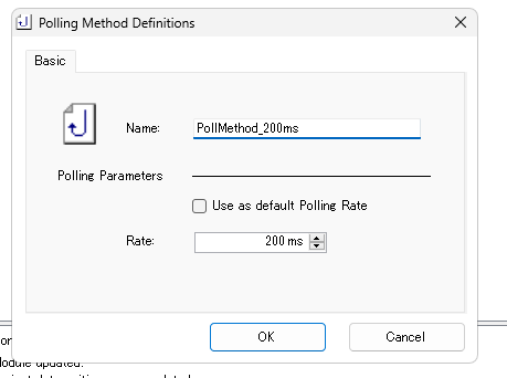
Done!A new Polling Method has been added.
Add Conversion Definitions
By using Conversion Definitions, the OPC UA Client side can convert the current value, e.g. Linear, without special programming.
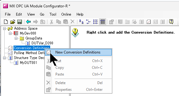
The Conversion Definitions configuration screen will appear.
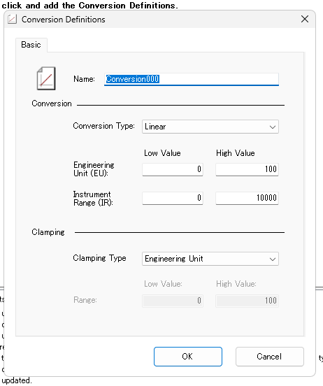
Conversion Type allows you to set the data conversion formula, which in this case is Linear, but please refer to the Manual for details.
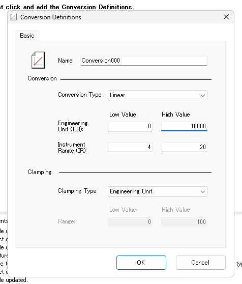
Next, the Engineering Unit and Instrument Range must be set.
The Instrument Range is the current value inside the CPU, and the Engineering Unit is the node that will be converted from the Instrument Range and actually published to the OPC UA Server. So you can change it from 4-20 to 0-10000 for devices inside the CPU.
Done!
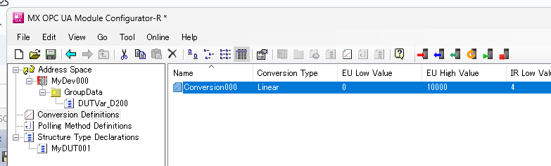
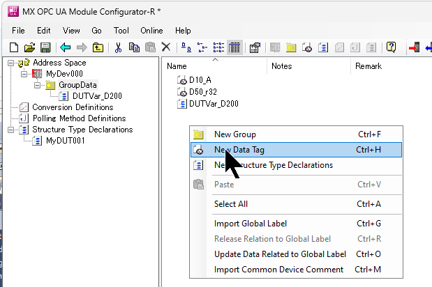
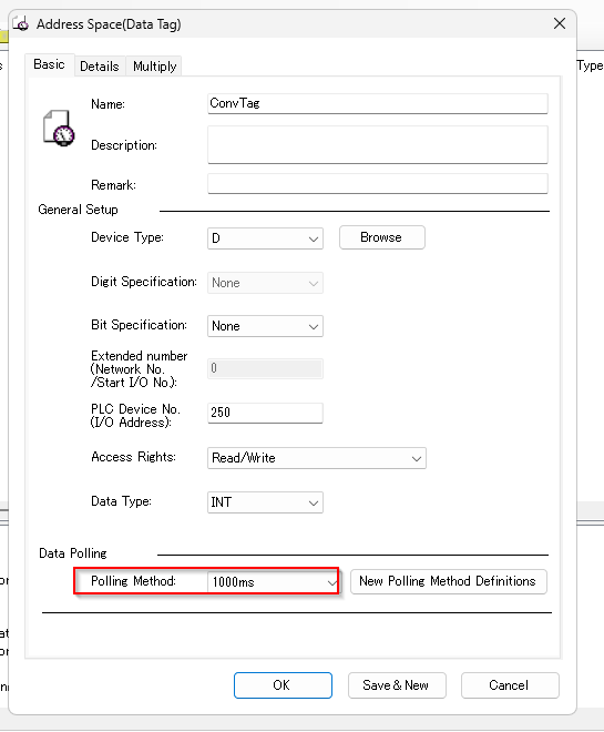
Add New Tag
The last step is to declare a new Data Tag.
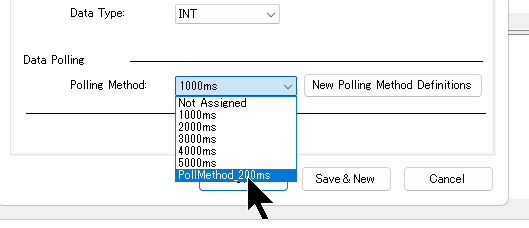
Polling Method is Default 1000 ms.
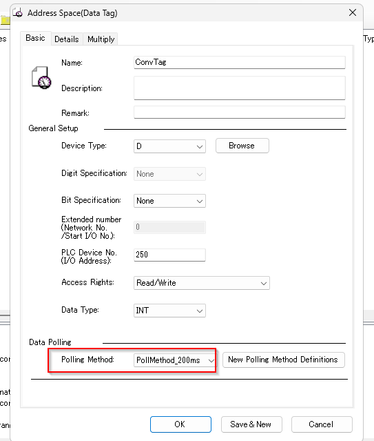
Set the PollMethod_200ms defined earlier from the Drop-List.
Done!
Next, open the Details Tab to set the Conversion Definitions.
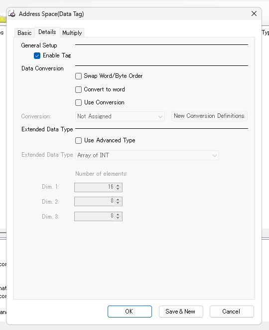
Please check the Use ConversionのCheckbox.
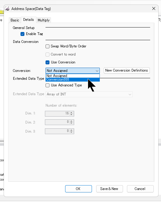
Conversion is Default and Not Assigned, but you can set the Conversion000 you defined earlier in the Drop-List.
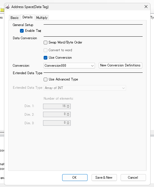
Done!
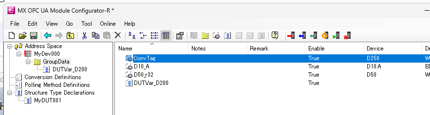
Result
You could search for the Node you have just defined from UaExpert.
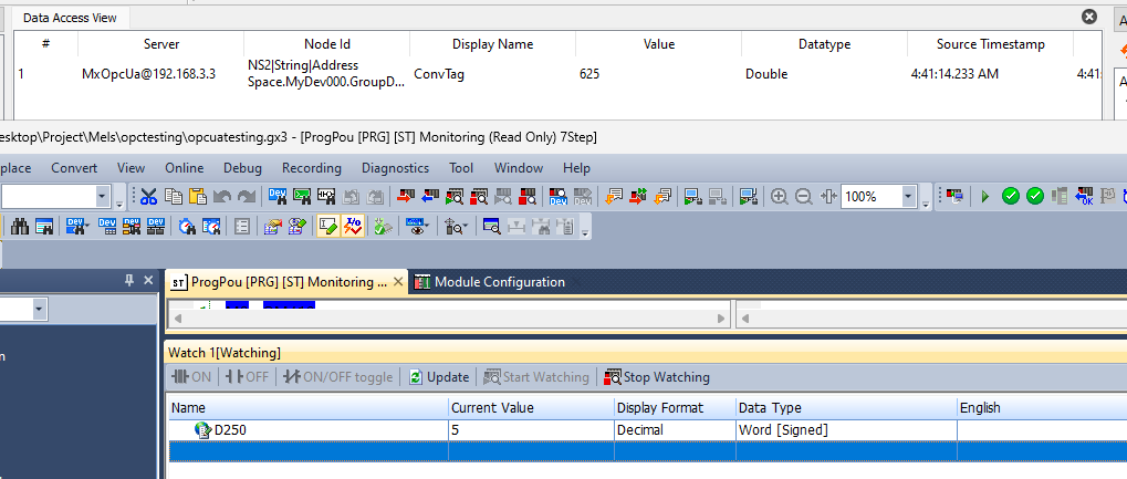
If the CPU D250 of the IQ-R is set to 13, the current value of the actual ConvTag is about 5625 Linear.
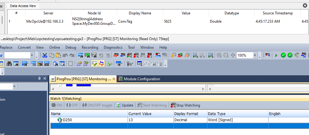
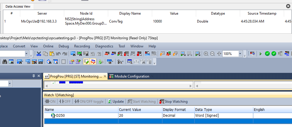
And when D250 was changed to 20, the ConvTag became 10000.
Implementation6‐Import From Global Label
In this article, we will show you how to import a Global Label in a GXWORKS3 project.
Add Structured Data Type
To verify how far RD81OPC96 can import complex structures, it declares data types in the GXWORKS3 project.
Add Global Label
Declare variables using the structure you have just defined.
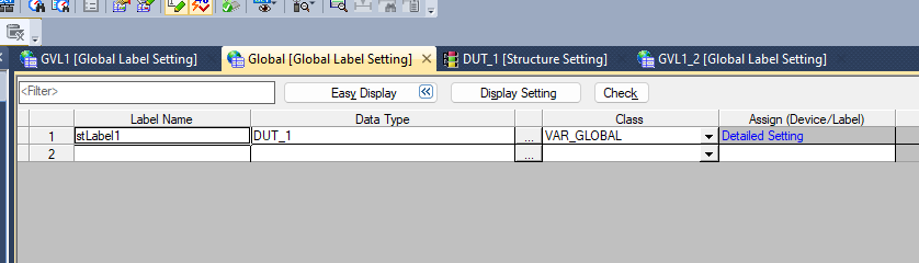
And also declare various variables in multiple GVLs.
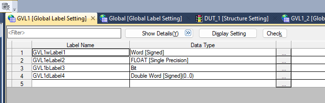
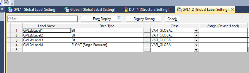
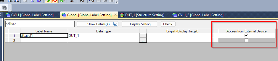
Finally, please tick the Access from External Device checkbox.
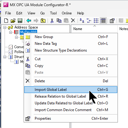
Import Global Label
Now right-click on Address Space>Import Global Label to import the GXWORKS3 Globel Label to RD81OPC96.
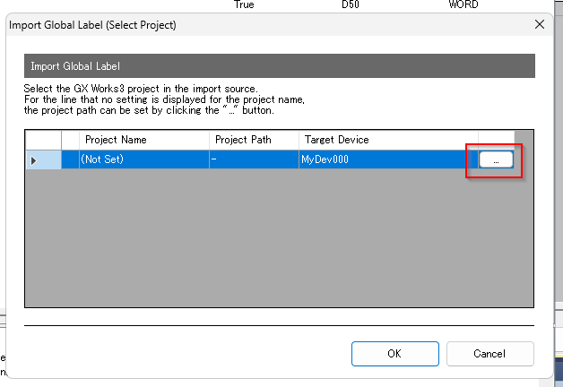
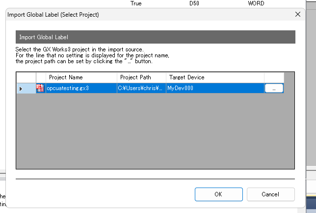
The Import Global Label configuration screen appears.
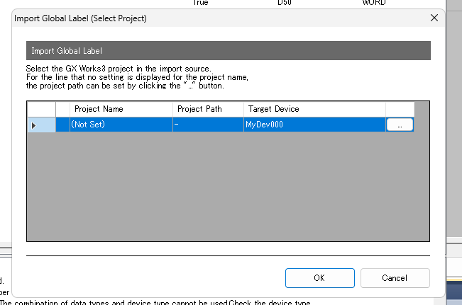
To configure GXWORKS3, click on the … button in the red frame.
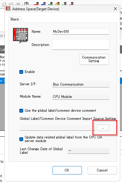
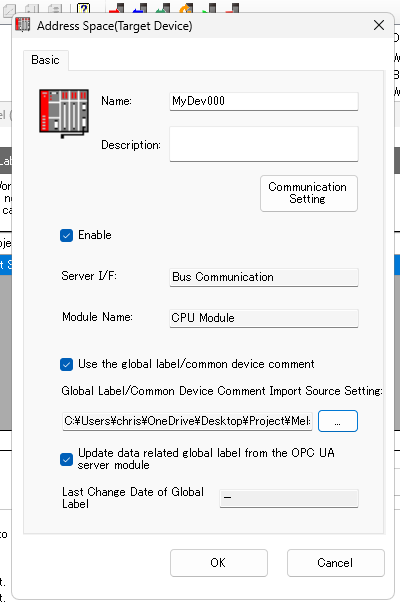
The Address Space configuration screen appears.
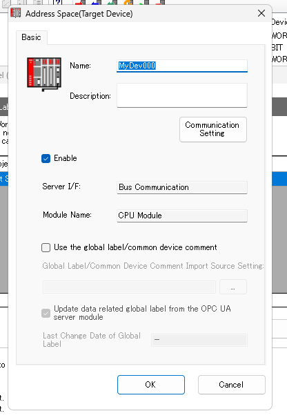
Checkbox under Use the Global label/common device comment.
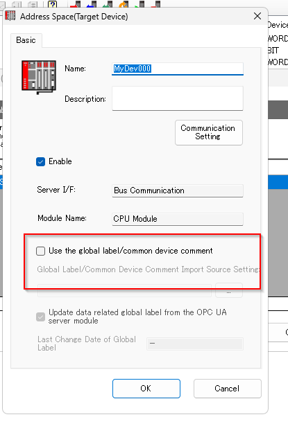
Click on the … button in the red frame to set the source GXWORKS3 project.
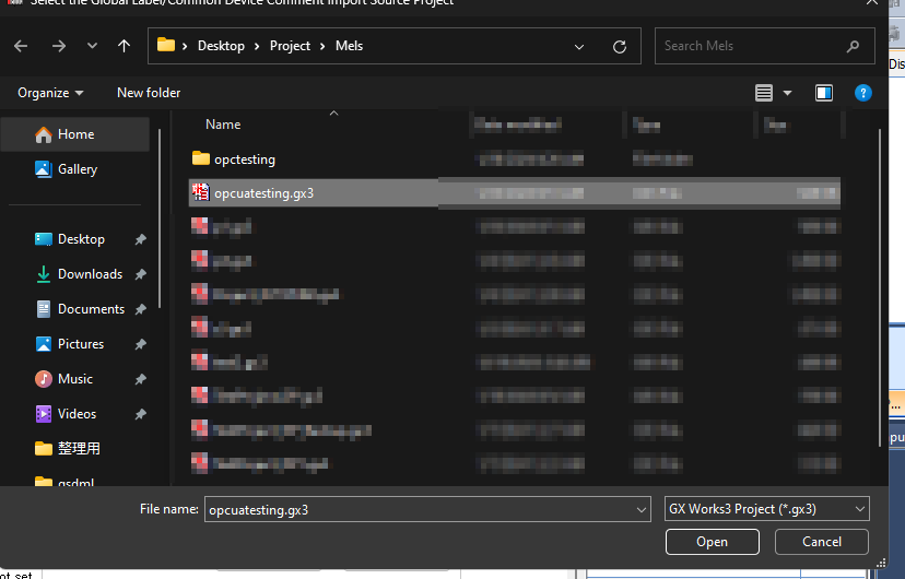
Done!Finally, click the Ok button to complete the configuration.
Proceed with Ok.
Just a second..
Done!The Global Variables List in the GXWORKS3 project could be retrieved.
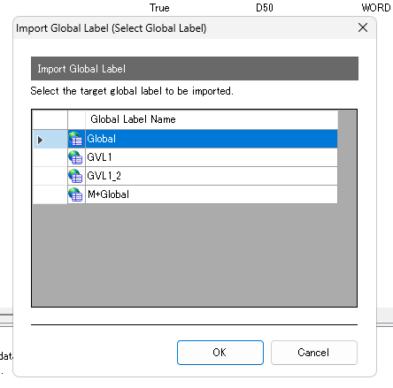
The Data selection screen is displayed.
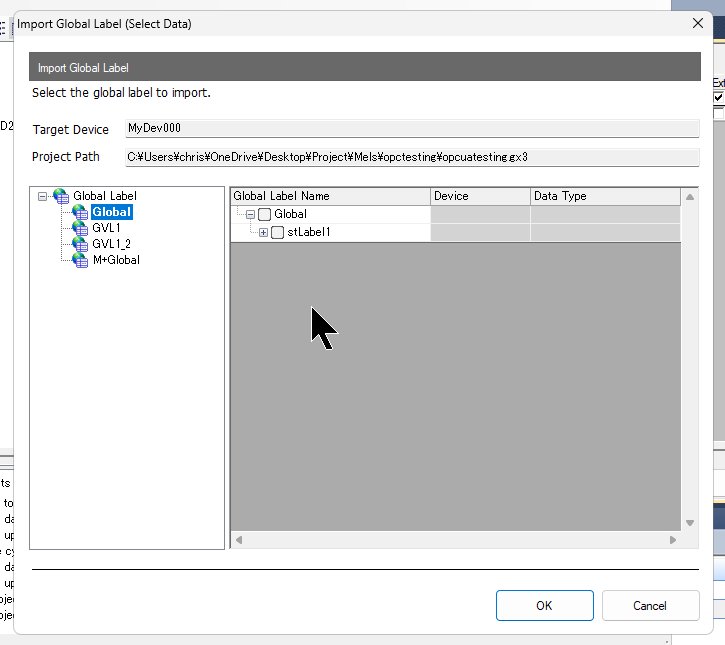
Set up the data required for your application.
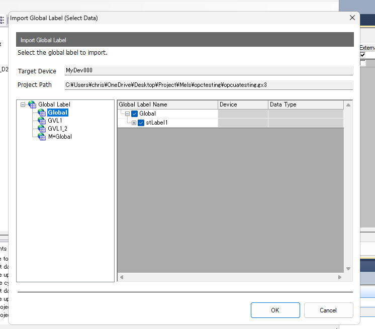
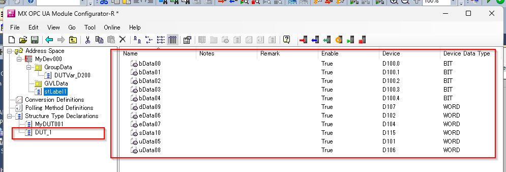
Done!Global Label has been Imported.
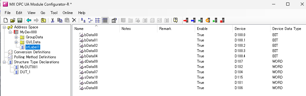
If there is a structure variable in the Global Variables List, the MX OPC UA Module Configurator will also automatically add the structure.
Ok.
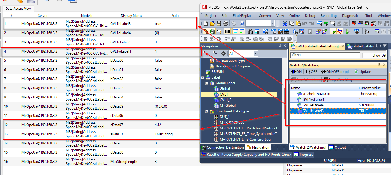
Result
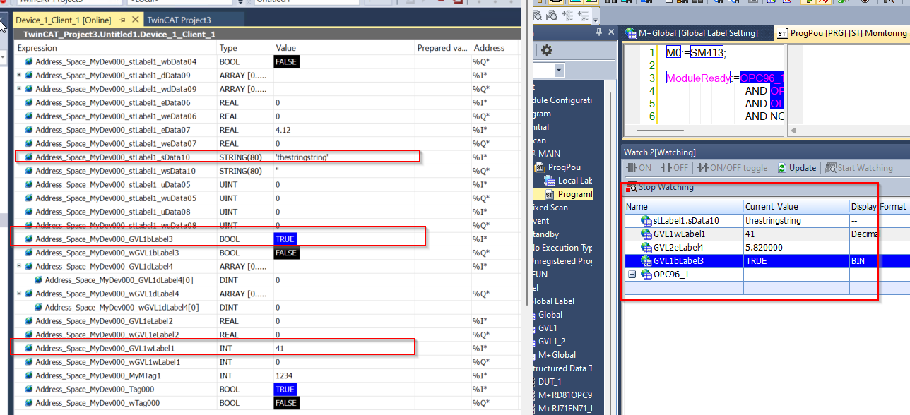
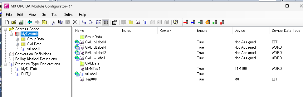
I was able to access RD81OPC96 using UaExpert and search for the Global Label that I had just Imported in MyDev000.
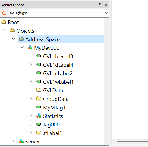
Add a Node to UaExpert to see the current value of each Node.
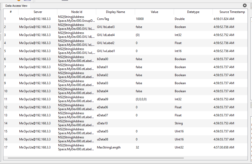
As shown in the diagram below, changing the current value of the Global Label variable from GXWORKS3 is reflected in UaExpert as well.
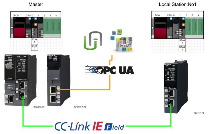
Implementation7‐Communicate with other Station
Implementation allows data from other stations to be retrieved and OPC UA Node-ised via the CC-Link IE Field network.
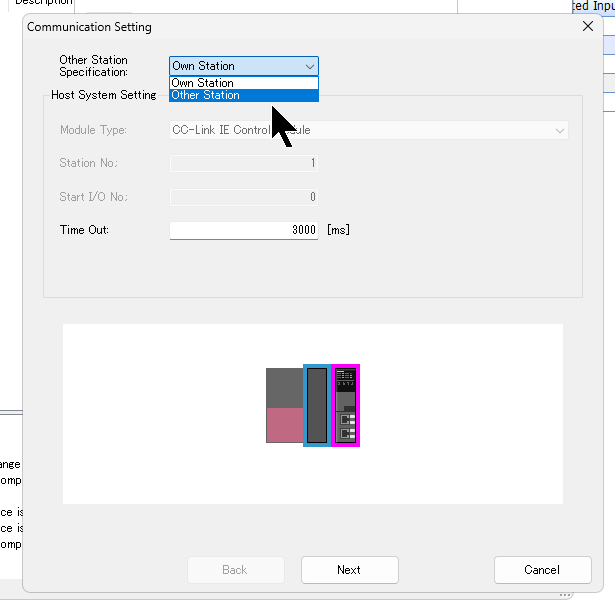
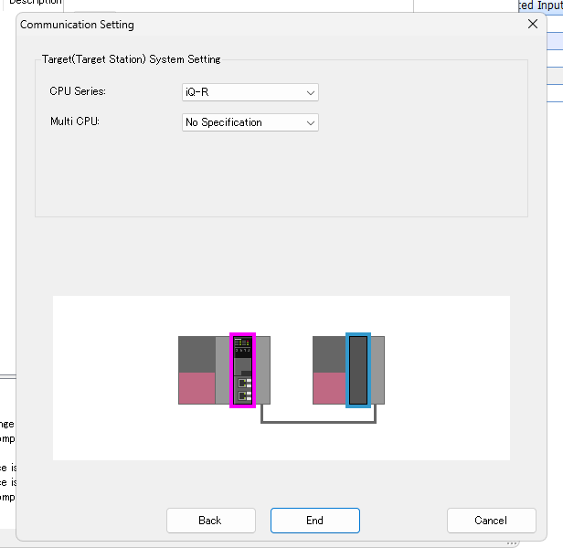
Communication Setting
Create a new Address Space in the project and click on Communication Setting.
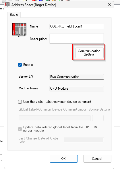
By Default, it is configured as Own Station, i.e. it has access to its own device.
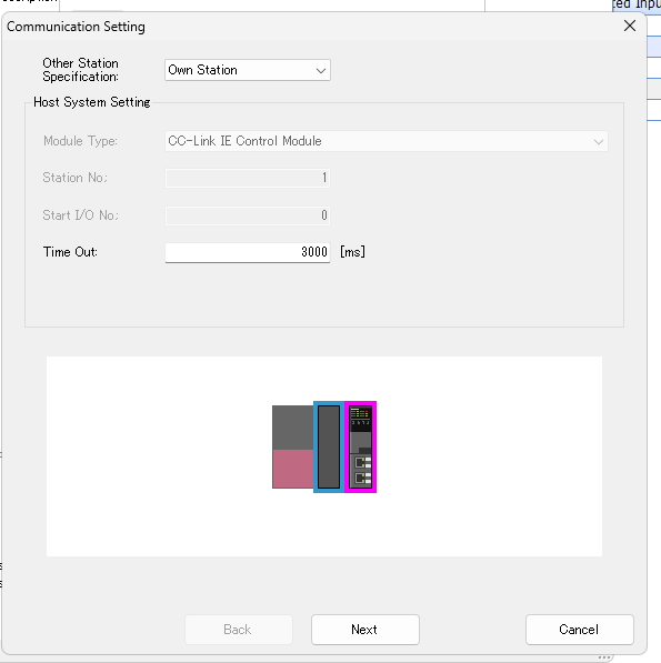
Configure Other Station from the Drop-List.
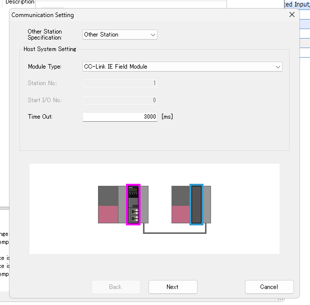
Configure how other Stations are accessed from the Drop-List in Module Type.
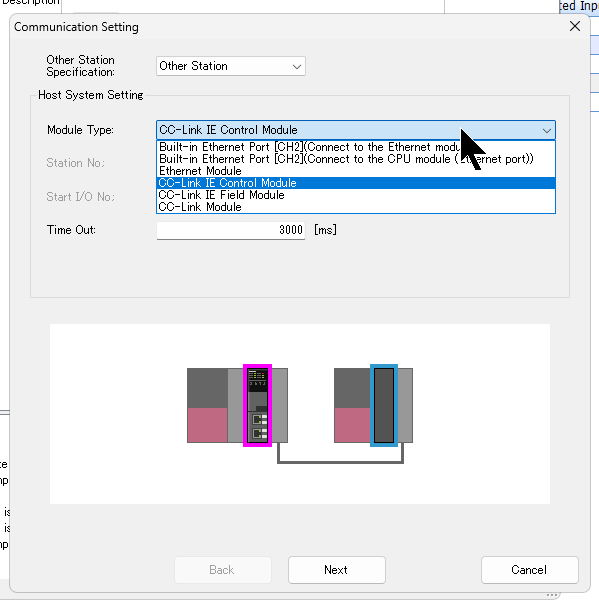
This time it will be the CC-Link IE Field Module.
Set the Station No and Network No to be accessed and proceed with Next.
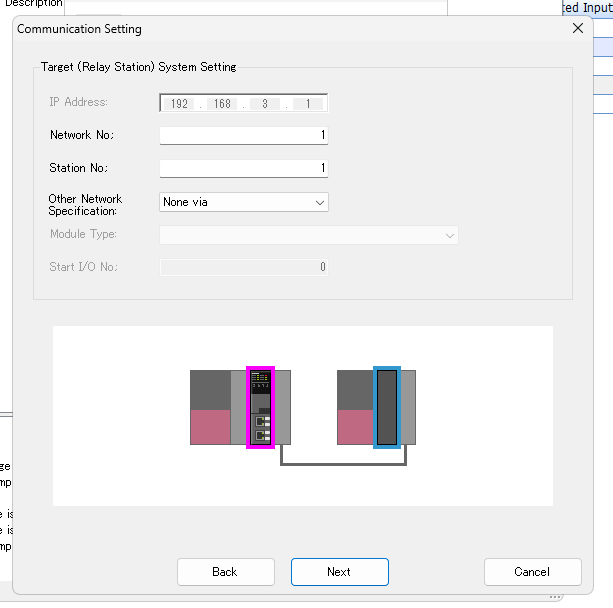
Set the CPU Series and other settings and complete the configuration with End.
The last step is to change the Address Space name.
Add Data Tag
Select the Address Space of the Access Station via the CC-Link IE Field that you have just added > Right-click and add a New Data Tag.
This time, M0 is to be accessed.
Result
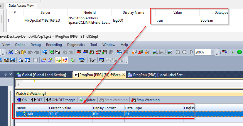
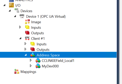
Access RD81OPC96 using UaExpert and there is an Address Source called CCLINKFIELD_Local1.
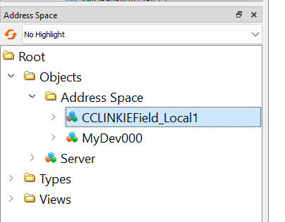
Done!It is a little difficult to see in the diagram below, but when M0 in Local Station 1 of the CC-Link IE Field was set to True, Tag000 in CCLINKFIELD_Local1 was also reflected in the same way.
Implementation8‐PLC Program
Implementation allows the PLC programme to check the status of the RD82OPC96 and perform reset operations.
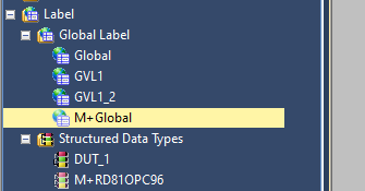
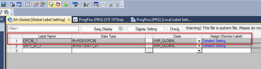
M+Global
After the RD81OPC96 module has been added, there is a structure variable named OPC96_1 in the Global Label M+Global.
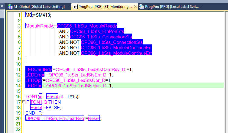
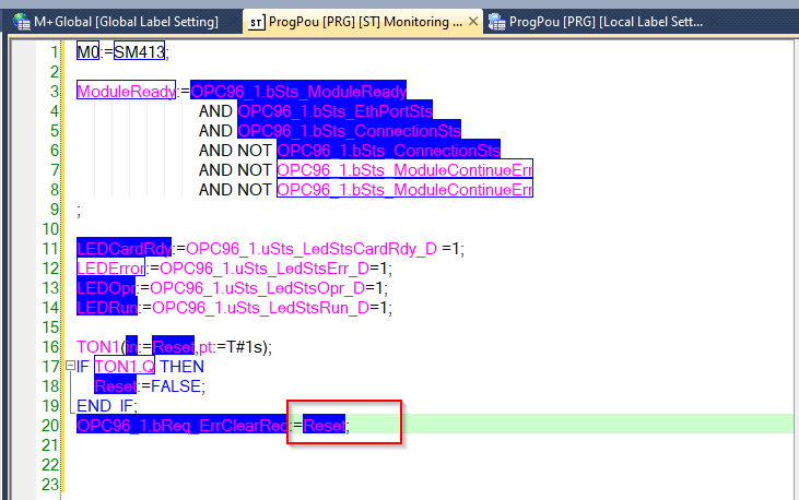
MAIN
| M0:=SM413; ModuleReady:=OPC96_1.bSts_ModuleReady AND OPC96_1.bSts_EthPortSts AND OPC96_1.bSts_ConnectionSts AND NOT OPC96_1.bSts_ConnectionSts AND NOT OPC96_1.bSts_ModuleContinueErr AND NOT OPC96_1.bSts_ModuleContinueErr ; LEDCardRdy:=OPC96_1.uSts_LedStsCardRdy_D =1; LEDError:=OPC96_1.uSts_LedStsErr_D=1; LEDOpr:=OPC96_1.uSts_LedStsOpr_D=1; LEDRun:=OPC96_1.uSts_LedStsRun_D=1; TON1(in:=Reset,pt:=T#1s); IF TON1.Q THEN Reset:=FALSE; END_IF; OPC96_1.bReq_ErrClearReq:=Reset; |
Result
Done!The status of module RD81OPC96 is currently available!
The RD81OPC96 can now also be reset in the event of an error.
Implementation9‐Access From TwinCAT3
Finally, we also test the connection from the Beckhoff TwinCAT to the RD81OPC96 instead of the UaExpert.
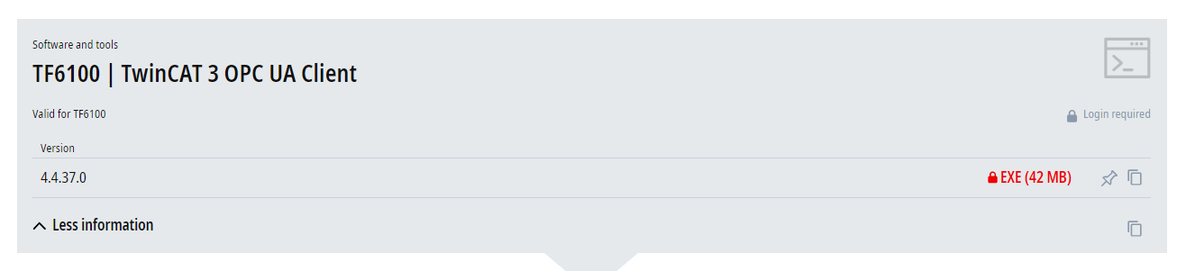
Install Packages
To use the OPC UA Client with Beckhoff TwinCAT3, install the following Package.
Add Devices
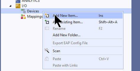
Add new Devices under Devices>Add New Item.
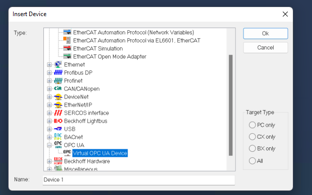
Select OPC UA>Virtual OPC UA Device>Ok.
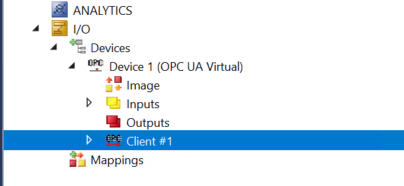
Add OPC UA Client
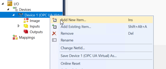
Add a new OPC UA Client under Device>Add New Item.
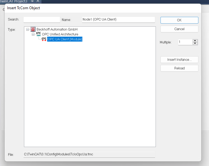
Add the OPC UA Client (Module).
SelectEndpoint
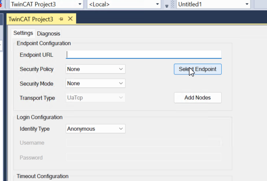
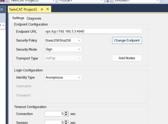
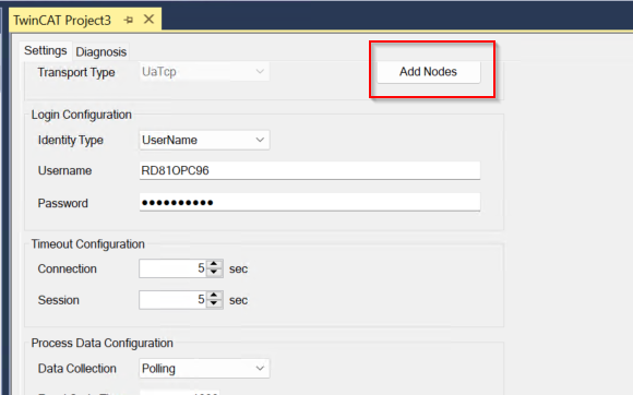
To configure the connection settings for the RD81OPC96, click on the Client you have just added.
Click Select Endpoint.
The Endpoint Discovery screen appears.
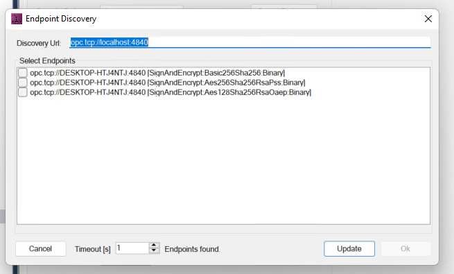
Enter the OPC UA Server Endpoint of RD81OPC96 in the Discovery Url.
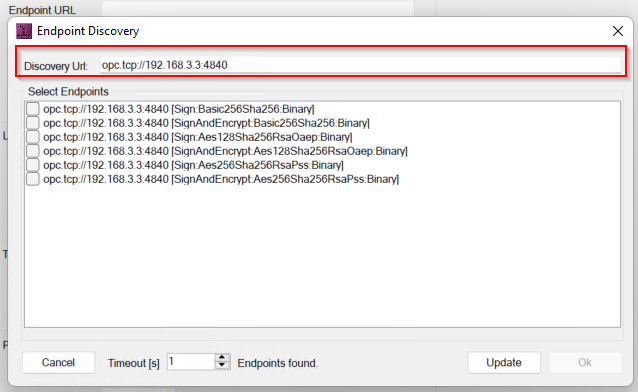
Select the Endpoints to be connected to the RD81OPC96.
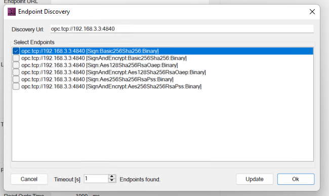
Done!
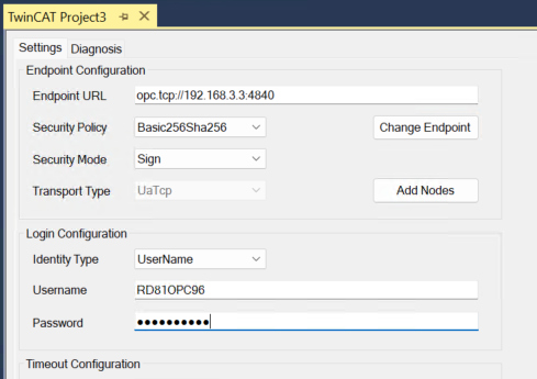
Identity Type
Connect RD81OPC96 using User and Password.
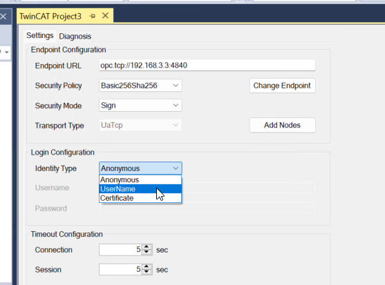
Username is RD81OPC96 and Password is MITSUBISHI.
Add Nodes
Click Add Nodes to access the RD81OPC96 OPC UA Server.
Click Trust to trust the certificate of RD81OPC96.
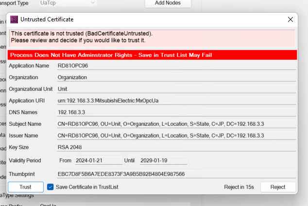
But the Server side returned a BadSecurityChecksFailed error.
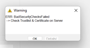
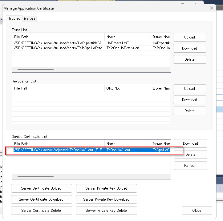
Configure the Certificate
Start the MX OPC UA Module Configurator-R and open Online>Manage Application Certificate.
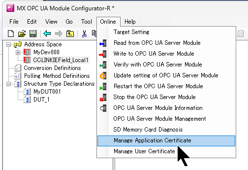
The Beckhoff TwinCAT3 Runtime certificate is on the Denied Certificate List.
Move the Beckhoff TwinCAT3 certificate to the Trust List using the same operation as in Implementation 1.
Add Nodes Again
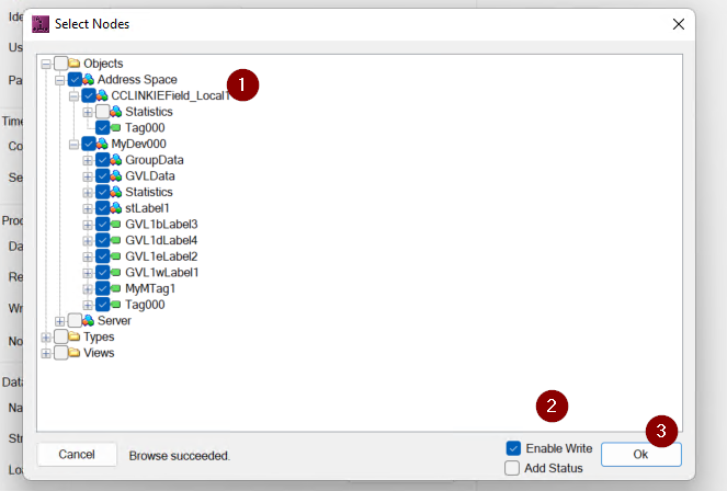
Done!This time, TwinCAT3 was able to access the RD81OPC96 Node.
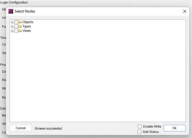
Choose the Node to access according to your application and proceed with >Ok.
Done!
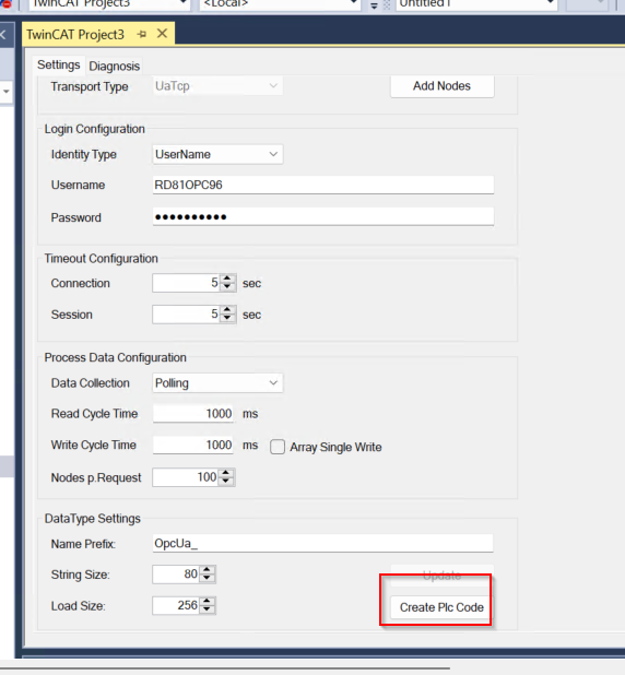
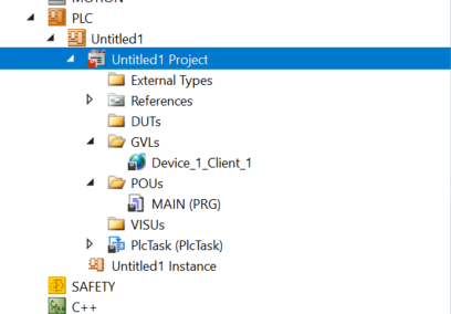
Create PLC Code
Click on the Create Plc Code button and the TF6100 will automatically generate all the variables.
Done!
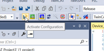
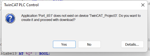
Activate Configuration
Finally, use Activate Configuration to Download the project to Runtime.
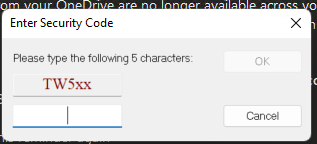
If there are not enough licences, enter the Trial licence.
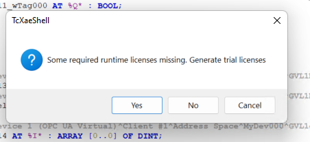
As long as you enter the Magic code, you can use it for 7 days. After 7 days, Runtime will stop once and you can activate the Trial license one more time.
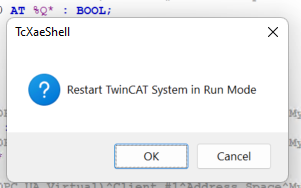
Switch the TwinCAT to Run Mode.
Login
Login to monitor results.
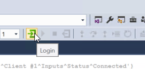
Proceed with Yes.
Start
Start Runtime with the Start button.
Be careful!
Note that when using the OPC UA Client with the “Add Node” function and Runtime, the OPC UA certificates are separate, so move the certificates to the Trust List once more.
Result
Done!TwinCAT3 was able to access the OPC UA Server Node of RD81OPC96.