This article introduces the CC-Link IE Field network construction method and basic knowledge.
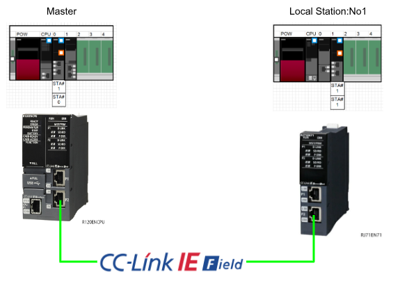
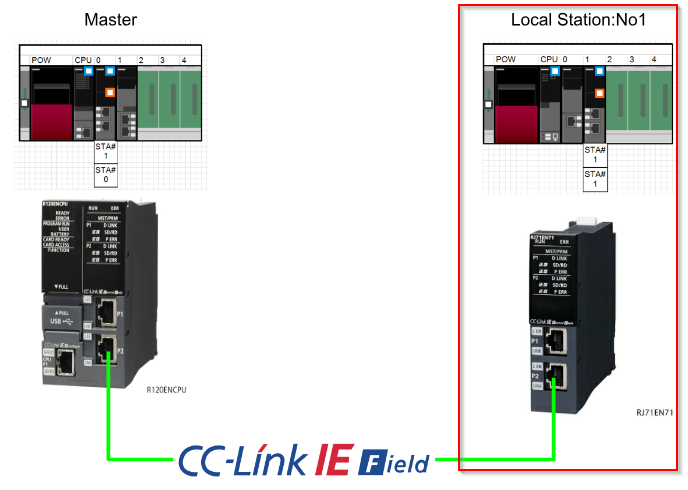
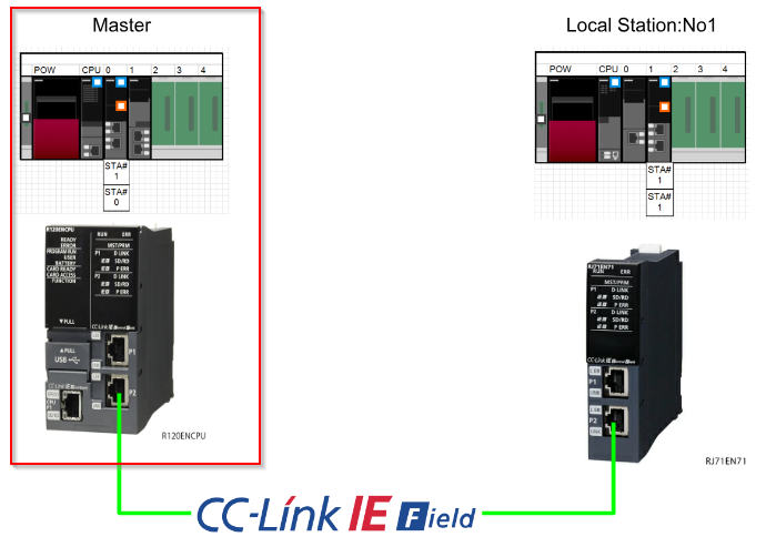
The Master side uses R120ENCPU and Local Station 1 is RJ71EN71.
Let’s get started!
CC-Link IE Field?
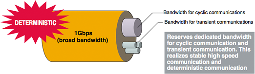
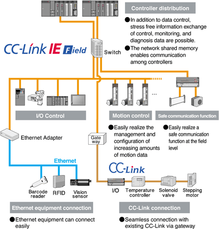
CC-Link IE Field is an ultra-fast, high-capacity network, providing both cyclic and asynchronous on-demand messaging communication.

Ultra High-speed
Gigabit transmission and real-time protocols allow easy and reliable data and remote I/O communication, independent of transmission delays.
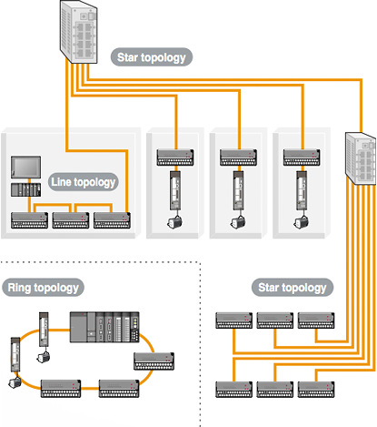
Easy Networking
Flexible network topology (ring, line and star possible) and network shared memory allows communication between controllers and field devices.
Easy configuration and network diagnostics reduce total engineering costs, from system start-up to maintenance.
Seamless Networking
CC-Link IE Field allows direct access to field devices from remote engineering tools across the network hierarchy. Devices can be monitored and configured from anywhere on the network, making engineering more efficient through remote management.
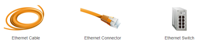
Ethernet Cable and Connector
The physical and data link layers of the CC-Link IE field network use standard Ethernet technology, so conventional cables, switches and hubs can be used. This increases the availability of materials and the choice of equipment required to install and adjust the network.
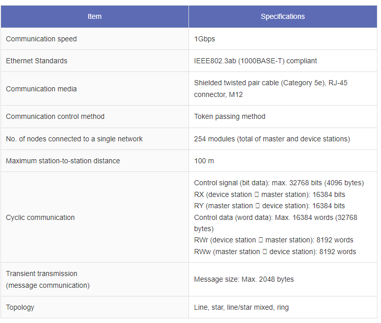
Specifications
Cyclic Transmission
Cyclic Transmission shares the data in the designated memory area with all other stations on the network and updates it automatically on a regular basis.
Transient Transmission
Transient TransmissionTransmission data is transmitted and received when there is an active request between stations, the timing of transmission follows that of cyclic transmission.
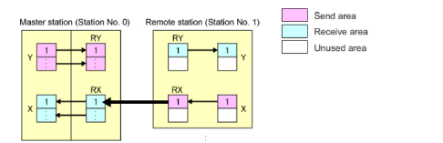
Link Devices
Link Devices are used by the network but are not directly accessible from the user programme. These devices allow for flexibility and scalability of the network.
- RY is used to transmit coil state information (Bit data).
- RWw device is used to transmit device value information.
- RX is used to receive device status information (Bit data).
- RWw device is used to receive device value information.
Station Type
CC-Link IE Field has several station types for different purposes, the most basic station type is:.
- Master Station
- Local Station
- Remote Station
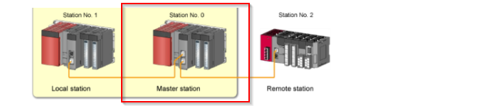
The master station contains the network configuration and is normally set to station number 0.The station number setting is optional as long as it is not duplicated.
Master Station
The Master Station contains the network settings and is normally set to station number 0.
The station number setting is optional as long as it is not duplicated.
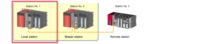
Local Station
The Local Station is an intelligent function module controlled by the CPU. This gives the Local Station more functionality than a remote I/O Station.
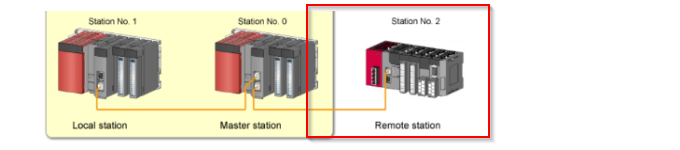
Remote Station
Remote stations do not have a control CPU and control modules and I/Os directly. Remote stations are not modules and therefore cannot run user programmes and are dependent on other network stations.
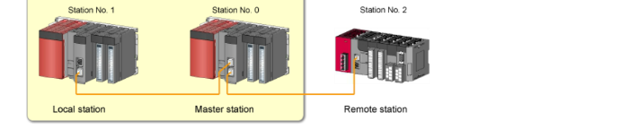
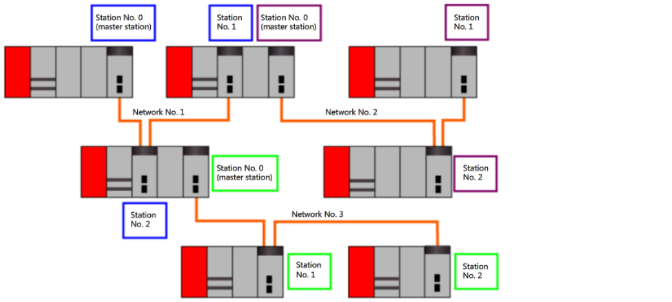
Station Example
As shown in the diagram below, a group of connected modules constitutes a network.
To pass data from one network to another, a system with two network modules, called relay stations, is required.
Splitting a large network into smaller networks provides benefits such as reduced traffic, increased available bandwidth, reduced ink scan times and improved reliability.
These include reduced ink scanning times and improved reliability. When separate networks are used, one network is usually isolated from the others in the event of a failure.
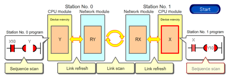
Transmission Delay Time
Transmission Delay Time is the time it takes for a change in the value of a device at one station to be reflected in a corresponding change in the device at another station. This delay time must be taken into account in systems that require accurate synchronization。
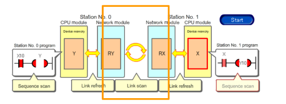
The CC-Link IE field network transmission processing cycle is shown in the diagram below.
In this case, station number 0 is the master station and transmits changes in the value of the Y device to the local station at station number 1.
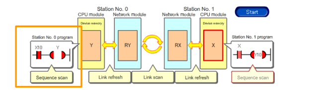
Sequence Scan In Station0
The programme of the master station (station no. 0) switches on device “Y”.
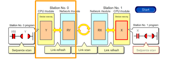
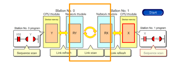
Link fresh in Station No.0
The Master Station at Station 0 processes Link fresh and reflects changes in the value of device “Y” in the Link Devices “RY” mapped in the network module.
Link Scan
During Link Scan, the value of RY is transferred via the network to the network module buffer memory of station No. 1, where it becomes Link Devices “RX”.
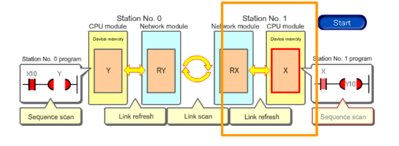
Link fresh in Station No.1
The Local Station in Station 1 processes Link fresh and reflects the value change of device “RX” to the matching device “x” in the CPU module.
Link Scan
During Link Scan, the value of RY is transferred via the network to the network module buffer memory of station No. 1, where it becomes Link Devices “RX”.
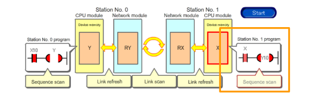
Sequence Scan In Station1
The programme of the local station (station no. 1) switches on device “X”.
Implementation
Local Station Side
It is built from the Local Station side.
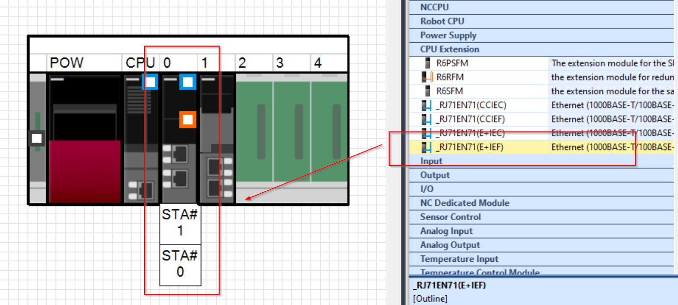
Add Module
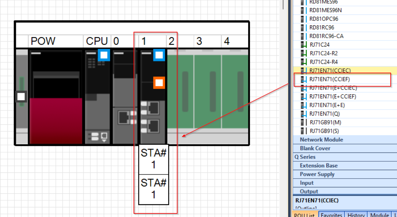
In Module Configuration, add the module used in this article, RJ71EN71.
As we will be using the CC-LINK IE Field network, add Options with CCIEF.
- RJ71EN71(CCIEF)
- RJ71EN71(E+CCIEF)
Either is acceptable.
Configuration
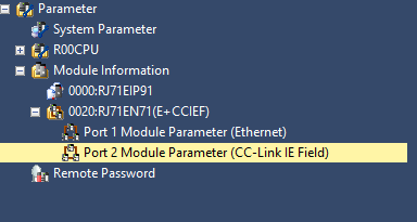
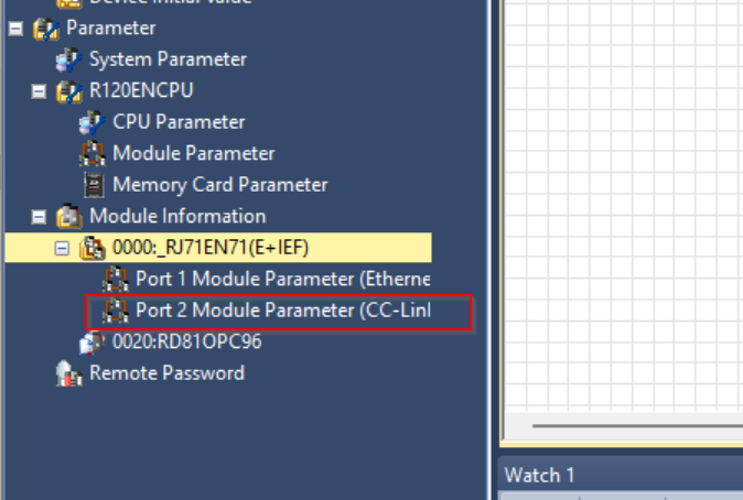
The next step is to set the parameters of the RJ71EN71 (E+CCIEF).
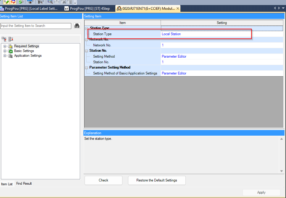
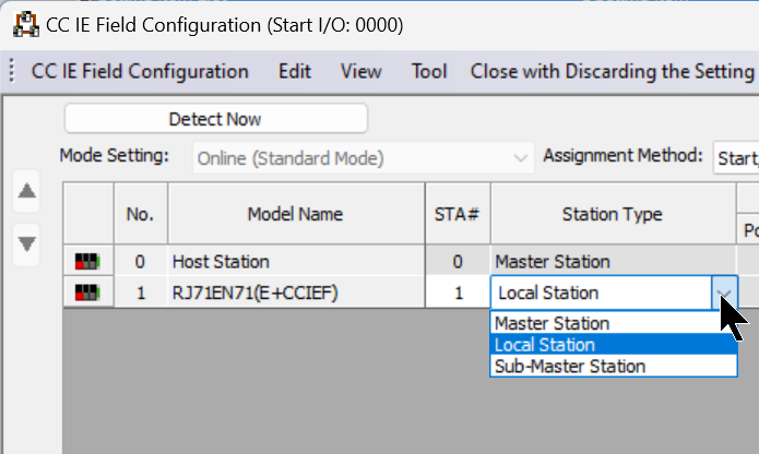
Station Type
Make sure that the Station Type is “Local Station”.
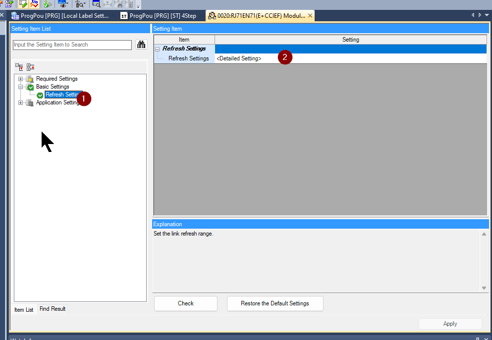
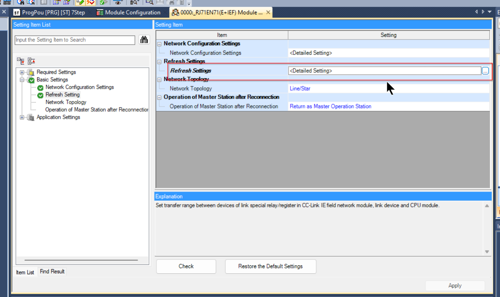
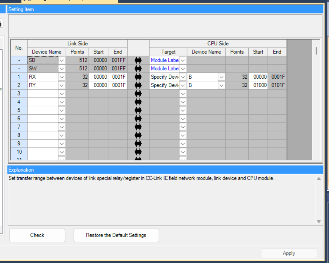
Refresh Setting
Refreshing Setting sets the Reflesh Link Devices section described earlier.
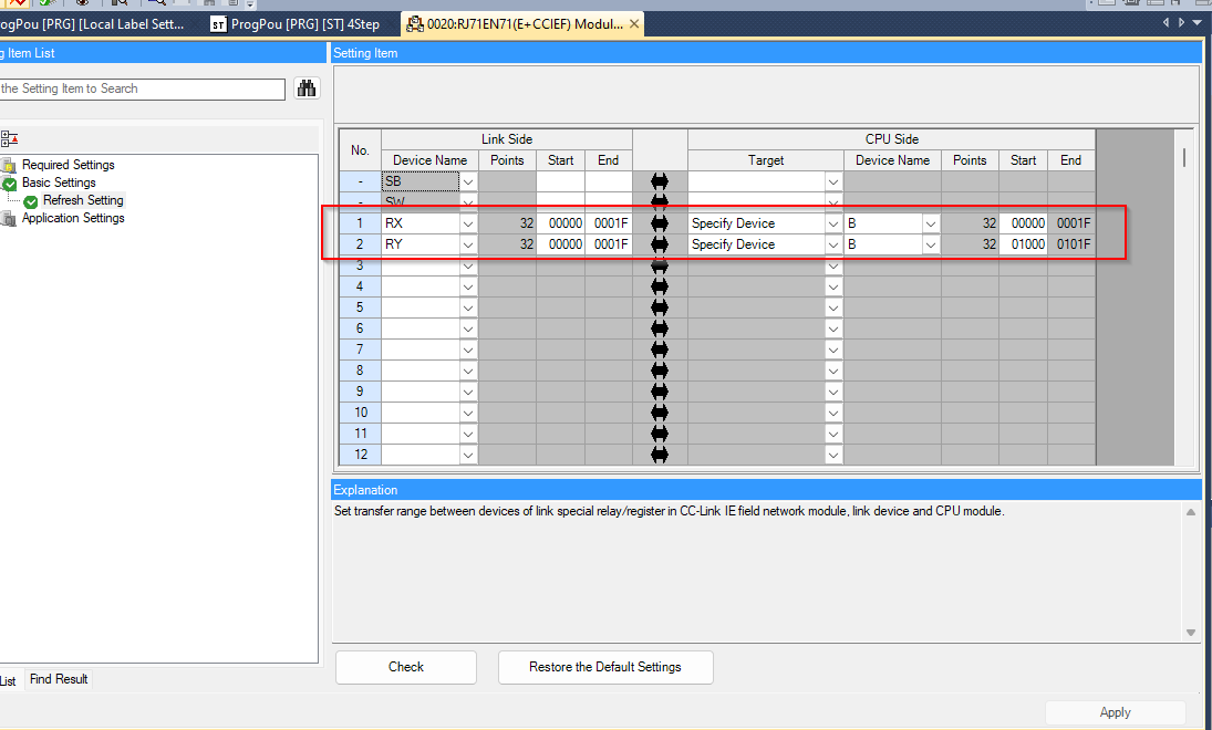
Add RX/RY and tie the data with Start=0000 and End=001F inside.
For CPU Side, set Device Name (device type, this time B, but actually you can also set X/Y/D/M etc.) and Start address. In the setting shown below, RX0000-RX001F is tied to B0000-001F and RY1000-RY101F.
Master Station Side
Now configure the Master Station side.
Add Module
In Module Configuration, add the CPU expansion module RJ71EN71 in the R120ENCPU used in this article.
As the CC-LINK IE Field network will be used, add the Options with CCIEF.
- RJ71EN71(CCIEF)
- RJ71EN71(E+CCIEF)
Either is acceptable.
Configuration
The next step is to set the parameters of the RJ71EN71 (E+CCIEF).
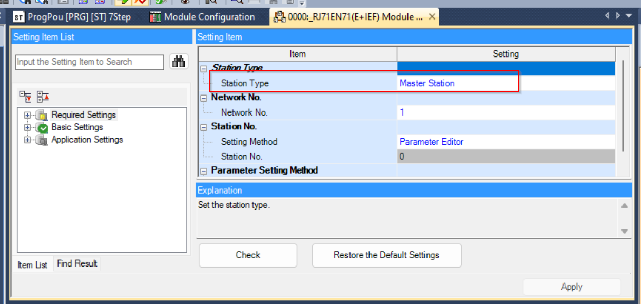
Station Type
Make sure that the Station Type is “Master Station”.
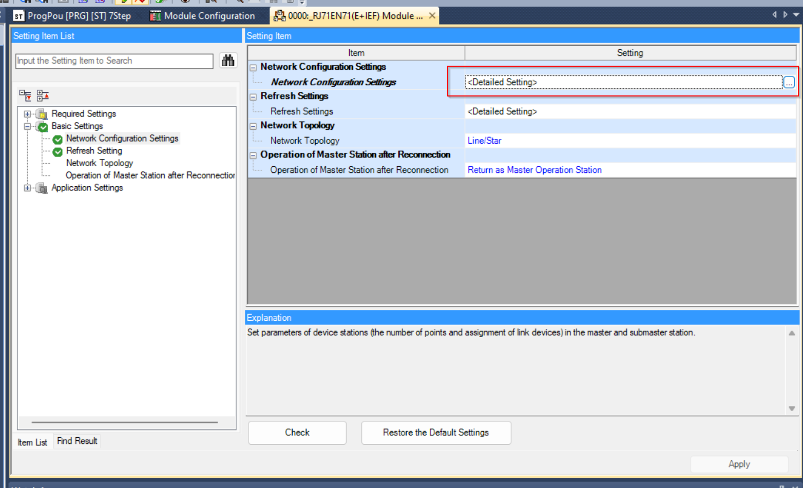
Network Configuration Settings
Go to Basic Setting>Network Configuration Settings and configure each Local Station.
CC IE Field Module (Mitsubishi Electric Corporation)>RJ71EN71(E+CCIEF).
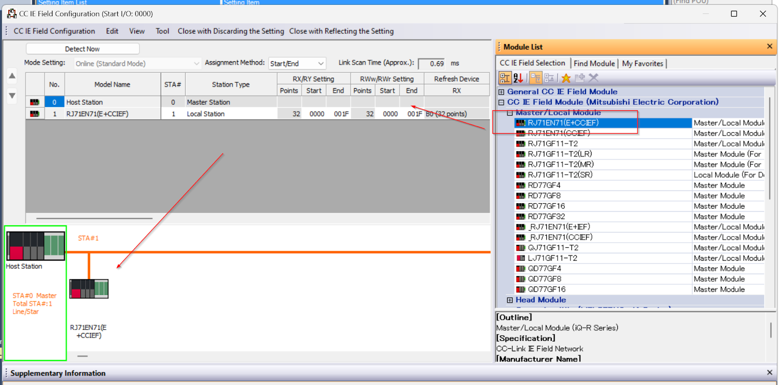
Set Station Tyoe to Local Station.
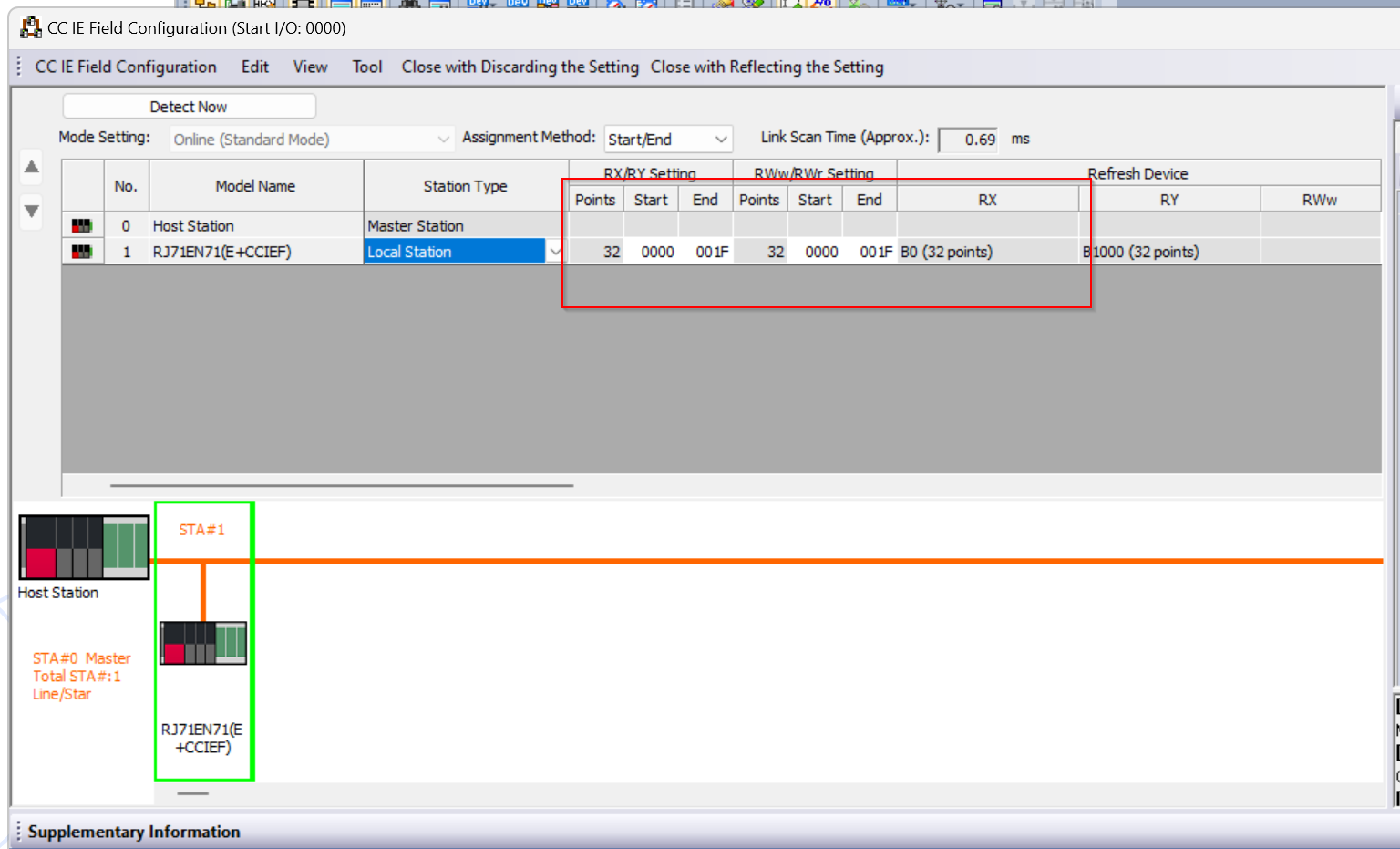
Set RX/RY Settings to Start00 and End 1F.
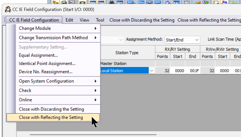
CC IE Field Configuration>Close with Reflecting the Setting to save your settings.
Refresh Settings
Refreshing Setting sets the Reflesh Link Devices section described earlier.
Add RX/RY and tie the data with Start=0000 and End=001F inside.
For CPU Side, set Device Name (device type, this time B, but actually you can also set X/Y/D/M etc.) and Start address. In the setting shown below, RX0000-RX001F is tied to B0000-001F and RY1000-RY101F.
Download
Download the project to the two CPUs as well and reset the power supply.
Result
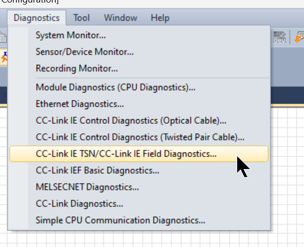
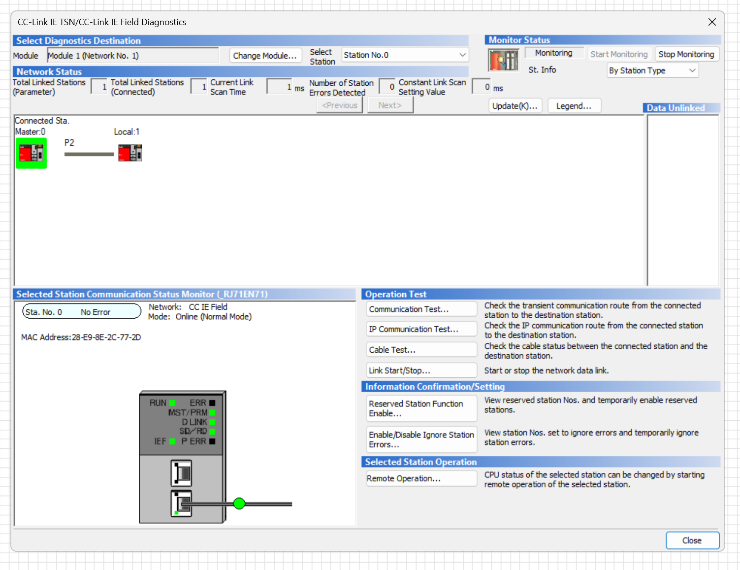
To monitor the CC-Link IE Field network on the Master Station CPU, click Diagnostics>CC-Link IE TSN/CC-Link IE Field Diagnostics.
Done!The Master Station and Local Station are now connected without error.
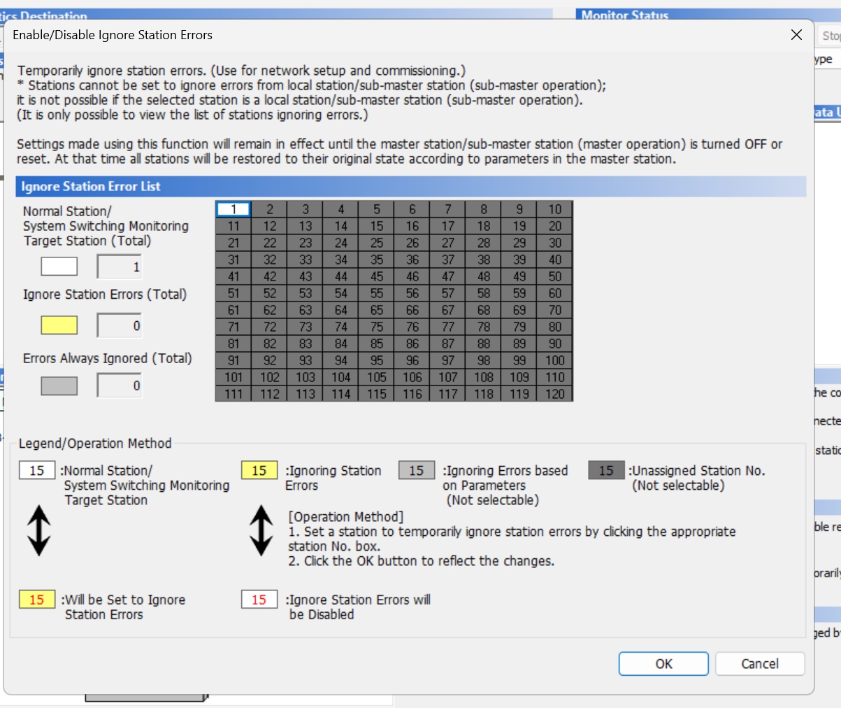
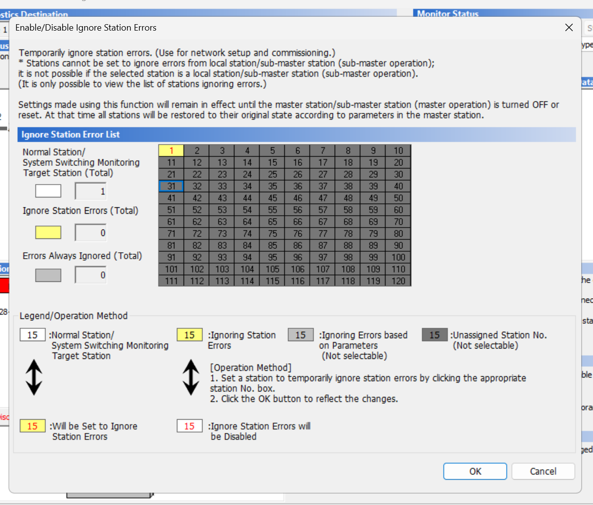
Open “Enable/Disable Ignore Station” and check the status of the Station now.
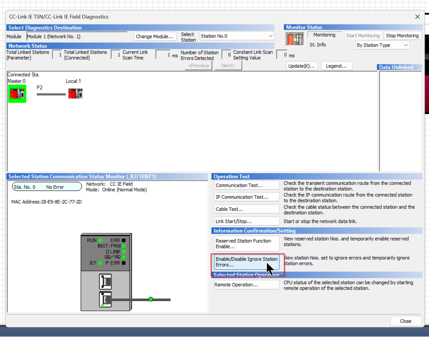
Master Station and Local Station are also in good condition.
Also, Station 1 is now white, i.e. Station 1 is Normal.
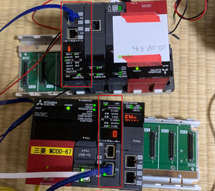
The next time I unplugged the LAN cable, the Master Station and Local Station also had the ERR LED on.
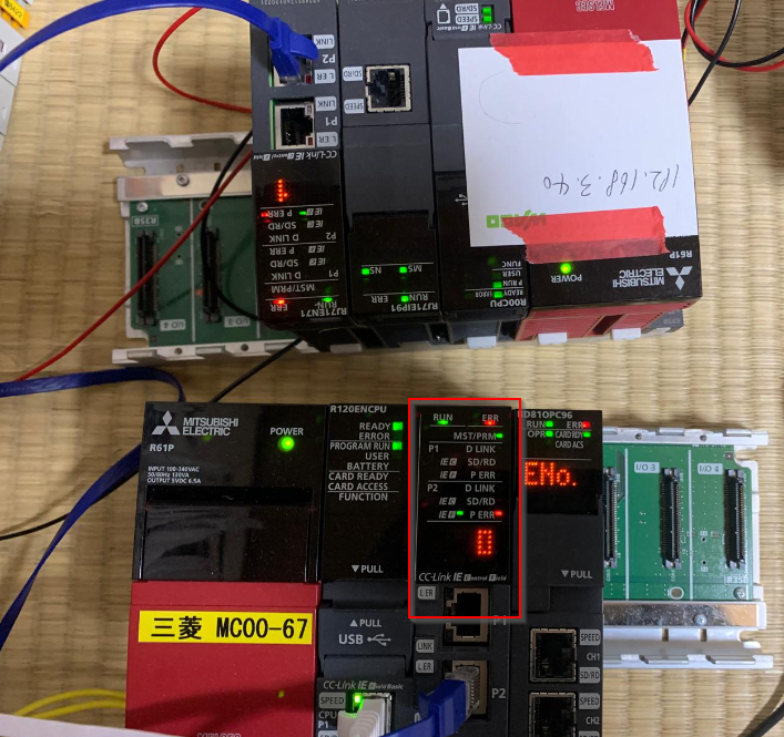
The CC-Link IE Field Diagnostics screen mentioned earlier shows that the Master Station and Local Station are now showing an error.
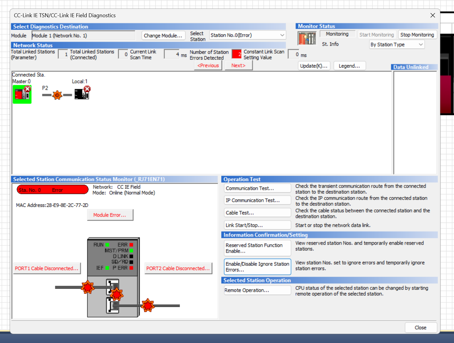
Local Station 1 is yellow, indicating that there is an error condition.
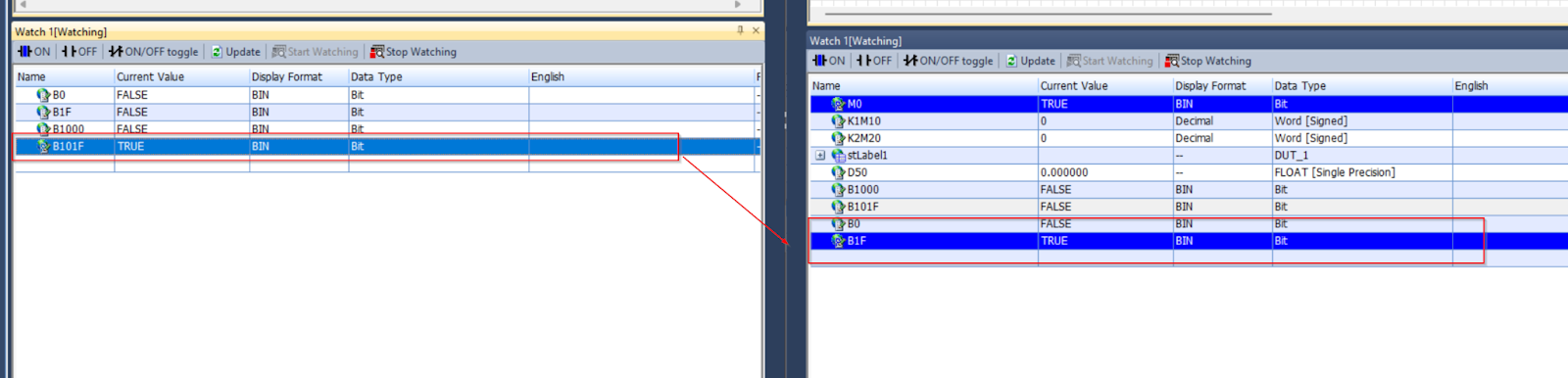
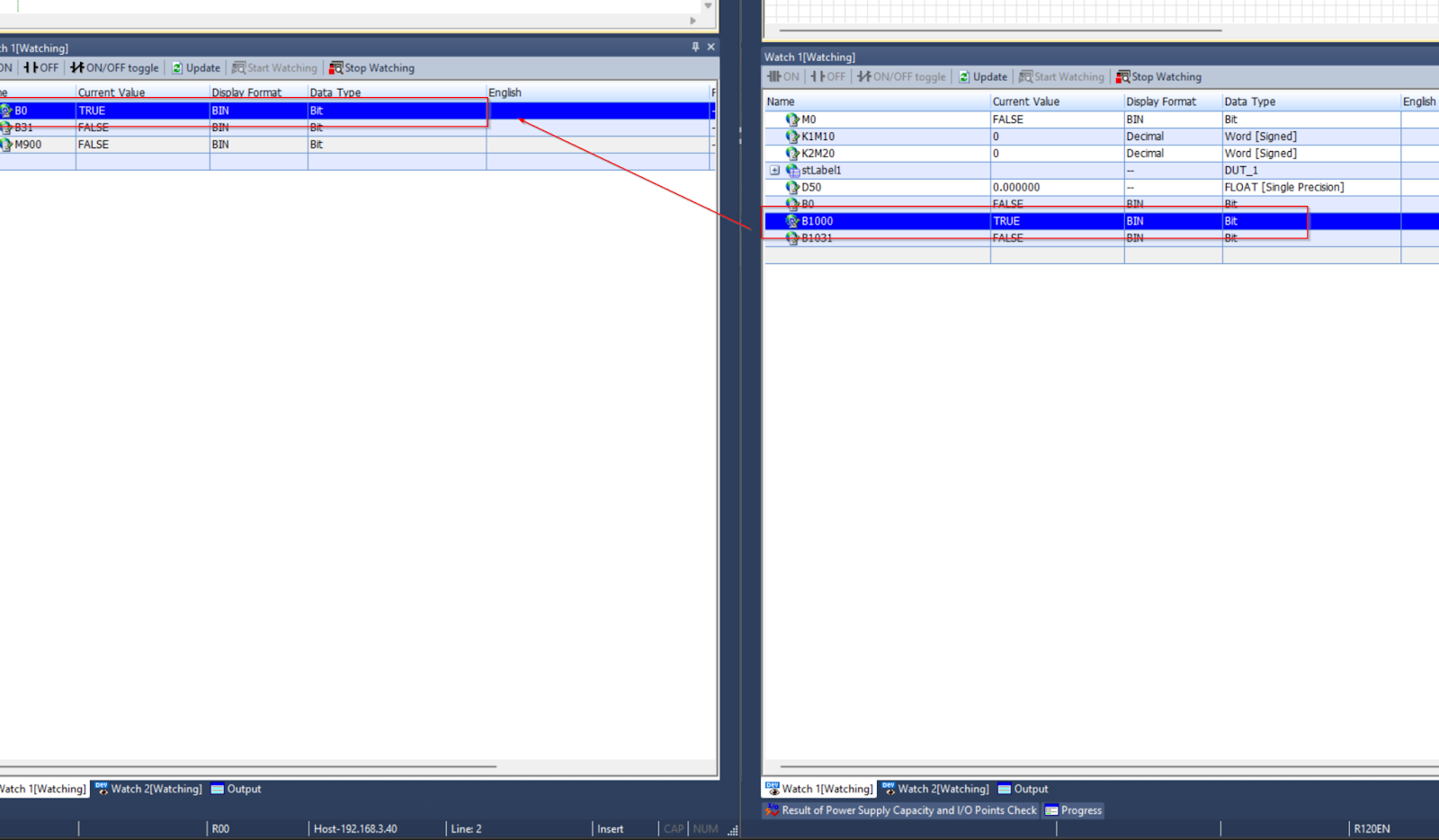
These are the Local Station and Master Station Watch Tables.
On the left is the Local Station and on the right is the Master Station.
The Master Station is Re-fleshed with B1001 set to True and the Local Station is Re-fleshed with B0000 set to True.
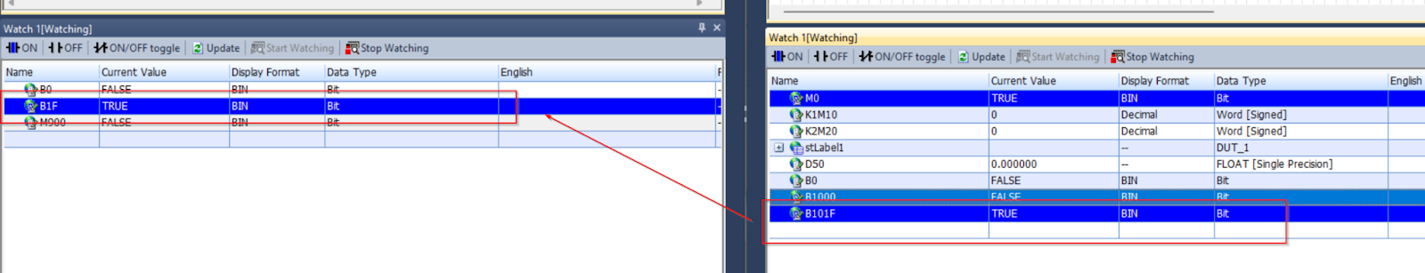
The Master Station is set to True for B101F, the Local Station is set to Re-flesh to True for B001F.
Now, conversely, if B1000 is set to True on the Local Station side, B0 on the Master Station will be reflected as True.
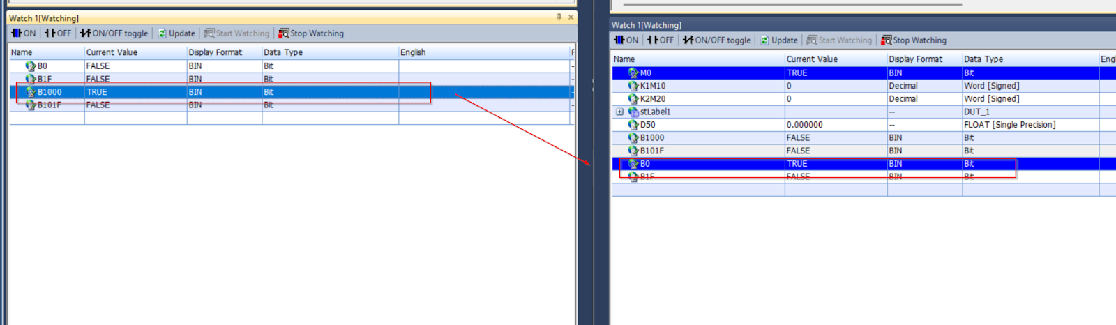
Finally, the Local Station sets B101F to True; the Master Station’s B1F is also set to True.