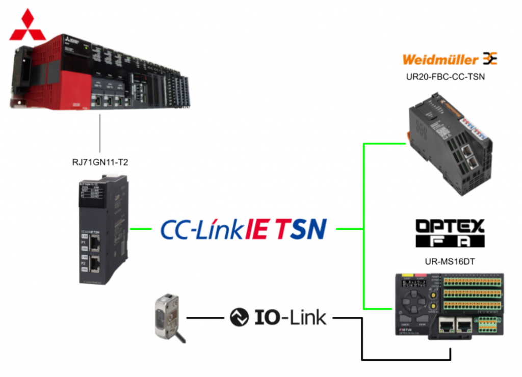
In this article, Mitsubishi IQ-R’s RJ71GN11-T2 is used to start up CC-Link IE TSN Master and CC-Link IE TSN Slave is connected to Weidmuller’s UR20-FBC-CC-TSN Coupler and OPTEX’s UR-MS16-DT.
In addition, knowledge about CC-Link IE TSN will be presented in the article.
Let’s get started!
TSN?
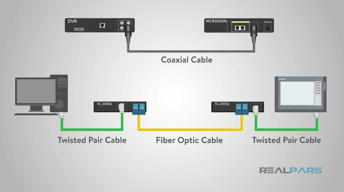
Ethernet is the world’s most popular communication medium for transmitting data between devices. Its speed, affordability, and versatility have made it popular in many industries.
And Ethernet standards have evolved over the years. In the 1970s, the first version of Ethernet only had a speed of 10 Mbps, but in 1995 Ethernet became available with a speed of 100 Mbps. Today, gigabit Ethernet is available.
In addition, as Ethernet has become ubiquitous in most industries, components have become more affordable and easier to implement. Therefore, Ethernet networks can employ a wide variety of protocols to realize their applications.
Even though Ethernet speeds are increasing year by year, there is another important performance factor: determinism. Deterministic networks must exchange data in a precise manner with a defined latency.
But because Ethernet communication is based on the best effort principle, data exchange in Ethernet networks lacks determinism. Standard information technology network equipment has no concept of “time” and cannot provide synchronization or precise timing. There are no constraints on the accuracy of delays or synchronization, as reliable delivery of data is more important than delivery within a specific time.
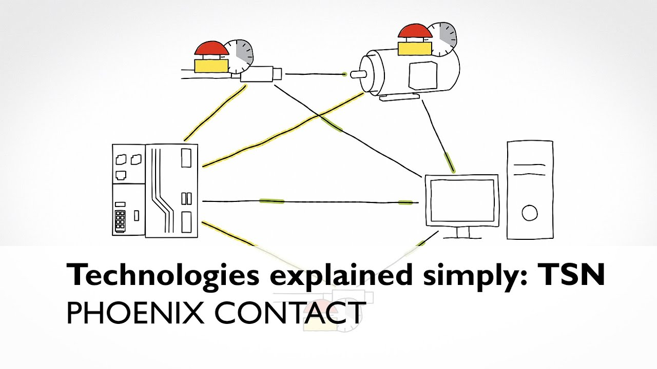
Time Sensitive Networking (TSN) aims to change that.
Each of the documents in the AVB/TSN standard specified in IEEE 802.1 can be divided into three basic key component categories.
Each standard specification can be used independently and is, for the most part, self-sufficient. However, only when used in concert can the TSN as a communication system realize its full potential. The three basic components are:
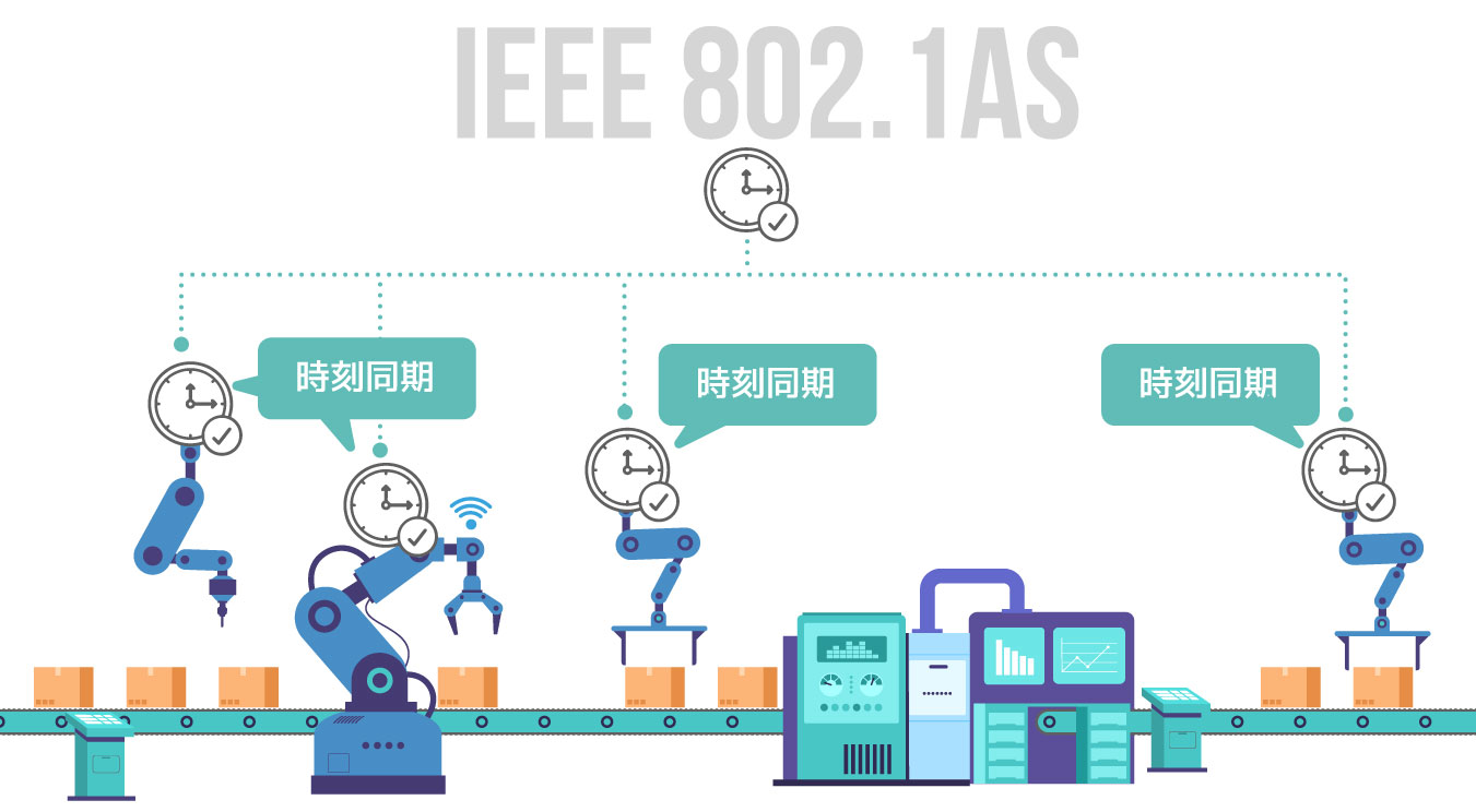
Time synchronization
Time synchronization: all devices participating in real-time communication must have a common understanding of time.
Scheduling and traffic shaping
Scheduling and traffic shaping: all devices participating in real-time communication follow the same rules in processing and forwarding communication packets.
WHAT IS TSN?
TSN is a set of IEEE 802 standards that make Ethernet deterministic by default: TSN is a new technology that sits at layer 2 of the ISO/OSI model and adds definitions to guarantee determinism and throughput in Ethernet networks. The following are some of the IEEE standards that make up TSN:
- Enhanced synchronization behavior (IEEE 802.1AS)
- Suspending (preemption) of long frames (IEEE 802.1-2018)
- Enhancements for scheduled traffic (IEEE 802.1Q-2018)
- Path control and bandwidth reservation (IEEE 802.1Q-2018)
- Seamless redundancy (IEEE 802.1CB)
- Stream reservation (IEEE 802.1Q-2018)
TSN evolved from the need for synchronized communication with more devices, with the industry using audio/video distribution. With more devices on the network than ever before, more information is being shared and analyzed. This is why Ethernet performs better.
TSN consists of several international standards. The main standards are IEEE802.1AS (specifying a time synchronisation method) and IEEE802.1Qbv (specifying a time sharing method). Combining these with the Ethernet standard enables punctuality, ensuring transmission within a certain time and mixed implementation with other communication protocols.
TSN FOR INDUSTRIAL AUTOMATION?
Many industries require deterministic Ethernet, and industrial automation is one of them. The automation industry has continually sought solutions that enable fast, deterministic and robust communication. Several solutions are now available specifically for this purpose, such as PROFINET IRT, Sercos III and Varan, and TSN can help standardize real-time Ethernet across the industry.
Current industrial trends such as Industrie 4.0 and the Industrial Internet of Things lead to increased network traffic in ever-expanding converged networks. Such networks require flexibility and scalability to support everything from small devices to big data server systems, while time-critical communication limits latency. TSNs are intended to cover all these requirements. TSNs are designed for deterministic Provides a standardized mechanism for the simultaneous use of deterministic and non-deterministic communications.
As mentioned earlier, the time sharing concept is the main concept for TSN. The implementation of 802.1AS (and in the future 802.1ASRev) by all network elements (end devices and bridges) is necessary for TSN.
The 802.1AS PTP profile allows all TSN network elements to share the same concept of time; the key to providing on-time delivery of TSN frames is that 802.1Qbv allows certain TSN Ethernet frames to be transmitted on a schedule, while non-TSN Ethernet frames on a best-effort basis around TSN frames.
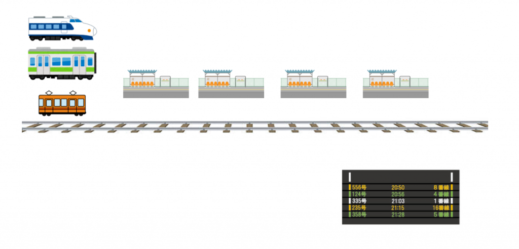
Because all network elements share the same time, end devices and bridges implementing Qbv can deliver critical communications very fast and without any discernible jitter in the delivery. A good example of IEEE 802.1Qbv is train systems.
The Ethernet bridges are seen as cities and the links between the bridges are seen as tracks between cities. There is one railway line between each city. Trains go from one city to another according to a schedule.
Rail tracks are a scarce resource that must be shared over time. No two trains can be on the tracks at the same time. The train system schedules the departure time of each train from the station, ensuring that the tracks are fully used and that there are no conflicts.
In TSNs, Ethernet bridges allow links to be used when there is unscheduled traffic. In the case of train systems, regional or local trains will use the tracks when intra-city trains are not using them.
CCLink TSN?
CC-Link IE TSN is the first product to combine Gigabit Ethernet bandwidth with Time-Sensitive Networking (TSN), further enhancing performance and functionality while increasing openness.

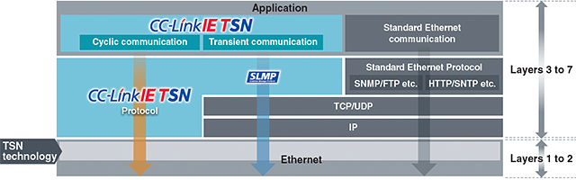
TSN technology and protocol layers
The CC-Link IE TSN protocol uses Layer 3 to Layer 2 of the OSI reference model, with Layer 2 being based on TSN technology.
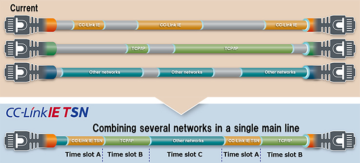
Integration of OT and IT
CCLink TSN enables control communication with real-time performance and integrates communication with other open networks and IT system information on the same network, thereby increasing flexibility in system configuration and reducing wiring costs.
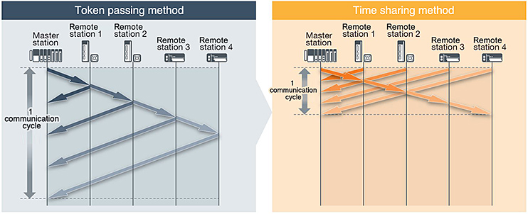
Communication methods
Conventional CC-Link IE uses the token passing method. After transmitting its own data, the station transfers its transmission rights to the next station by transferring its token.
CC-Link IE TSN uses a common time synchronized throughout the network. Input and output communication frames are transmitted simultaneously in both directions at a fixed time. Combining this method with TSN can reduce the network cyclic data update time.
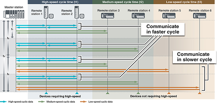
CC-Link IE TSN allows multiple communication cycles within the same network. This allows devices that do not require high-speed communication cycles, such as remote I/O, to be connected according to the characteristics of each device, while maintaining the performance of devices that require high-performance communication cycles, such as servo amplifiers.
This optimizes communication cycles, maximizes drive control performance, and reduces time.
Reduction for start-up, operation, and maintenance
CC-Link IE TSN also supports SNMP, and general-purpose SNMP monitoring tools can be used to analyze CC-Link IE TSN devices and IP communication devices such as switches and routers.
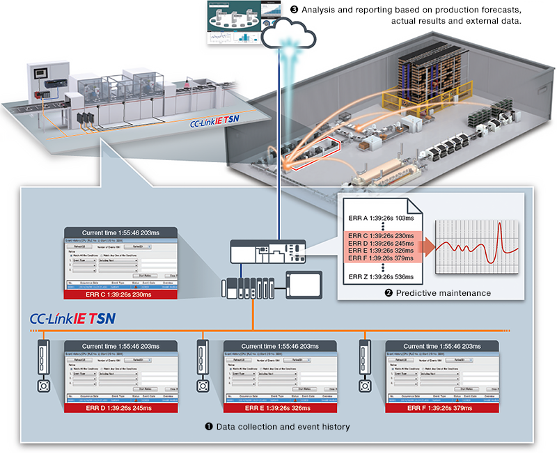
The time difference between CC-Link IE TSN-enabled devices is calibrated and kept synchronized with high precision using the time synchronization protocol specified by the TSN. Time information stored in both master and remote stations is thereby synchronized in microseconds.
In the event of a network error, the time information is synchronized in microseconds, which makes it possible to check the operation log and accurately trace the events up to the error in chronological order。
It is also possible to provide information on the production site and accurate time information to the IT system. This will enable AI-based data analysis, which is expected to further improve processes through predictive maintenance.
Compatible through various development methods
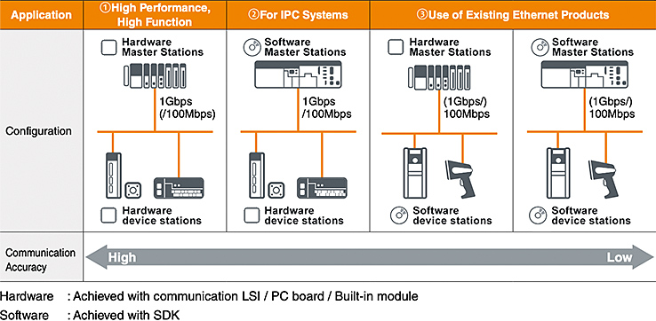
The CC-Link IE TSN supports implementation on both hardware and software platforms, with ASIC and FPGA-based hardware methods supported.
They are also available for both master stations and device stations. In both cases, 100 Mbit and 1 Gbit physical layers are supported.
This flexibility allows device vendors to develop their products in an optimal way while minimising time to market.
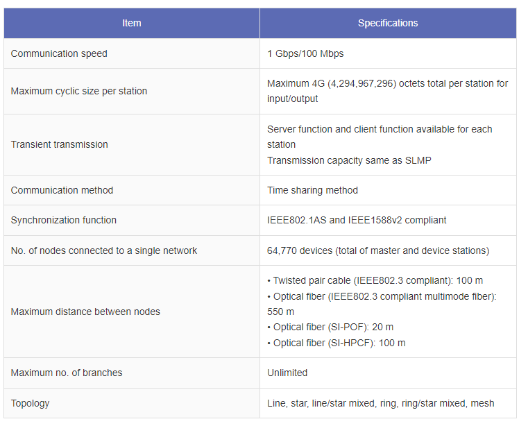
CC-Link IE TSN Specifications
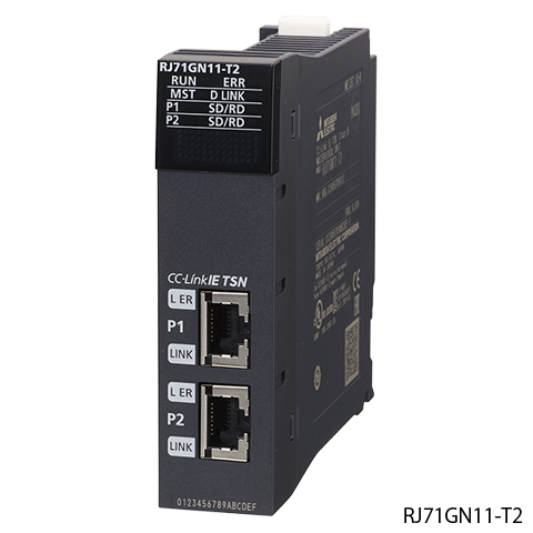
RJ71GN11‐T2
This module can be used as a master/local station for CC-Link IE TSN and can mix control communication, which requires real-time performance, with TCP/IP communication.
Network construction can also be easily achieved through automatic detection of network components and distribution of parameters to connecting stations.
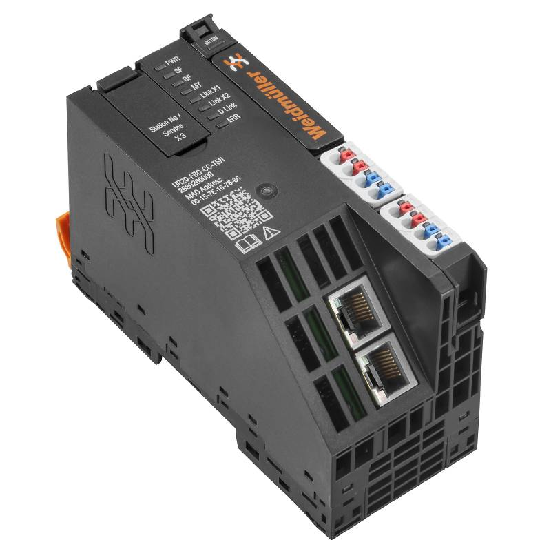
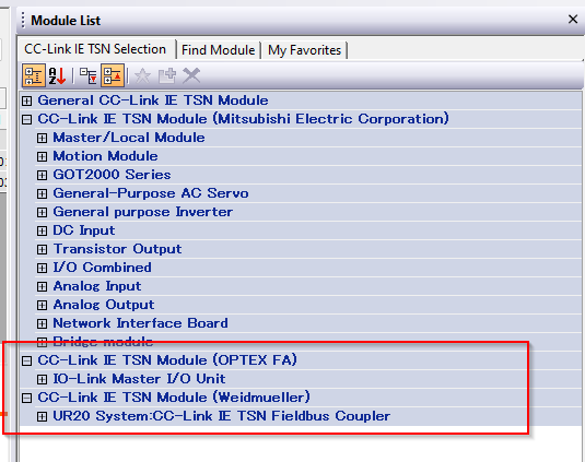
UR20-FBC-CC-TSN
The UR20-FBC-CC-TSN fieldbus coupler is a remote station (CC-Link IE TSN slave) compliant with the CC-Link IE TSN specification.
- CC-Link IE TSN-specific communication and associated services according to Class B possible
- Head module of the u-remote system bus allows connection of up to 64 active u-remote modules
- I/O data can be exchanged with CC-Link IE TSN master
- Diagnostics and alarms can be exchanged via the Alarm Message Protocol (SLMP)
- It can be accessed by a web server application via USB service interface or Ethernet.
- Diagnosis
- Status value
- Read parameters
- Simulate all connected modules
- Forced ON/OFF
The station’s mains power supply is also integrated in the coupler. Power is supplied from two 4-pole connectors, which are divided into input and output current paths.
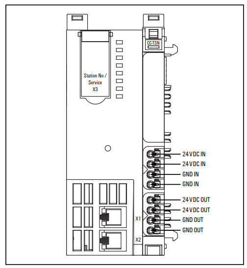
Power
This is the power supply wiring diagram for the UR20-FBC-CC-TSN.
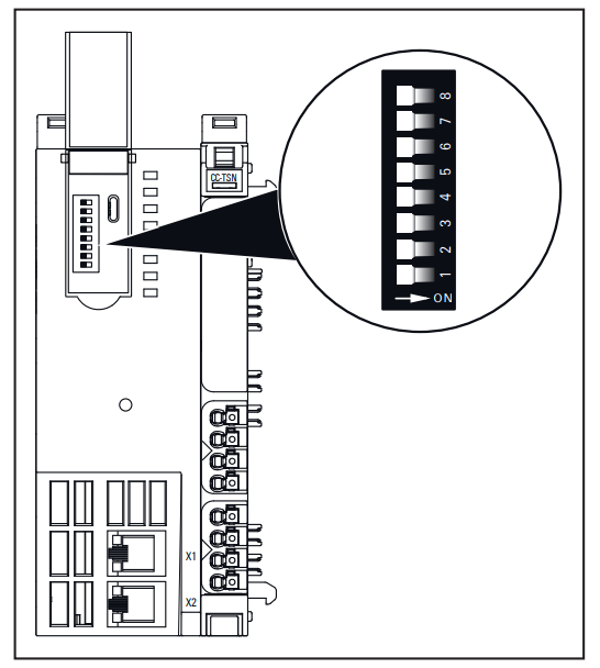
Addressing
The address of the fieldbus coupler can be set between 0 and 254 via a DIP switch. The address is recognised when the coupler is powered up.
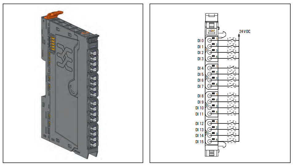
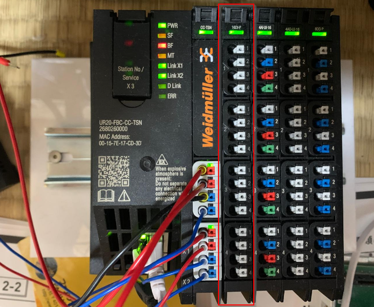
UR20-16DI-P
The UR20-16DI-P digital input module can detect up to 16 binary control signals. Four sensors can be connected to each connector in a one-wire configuration, with a status LED assigned to each channel.
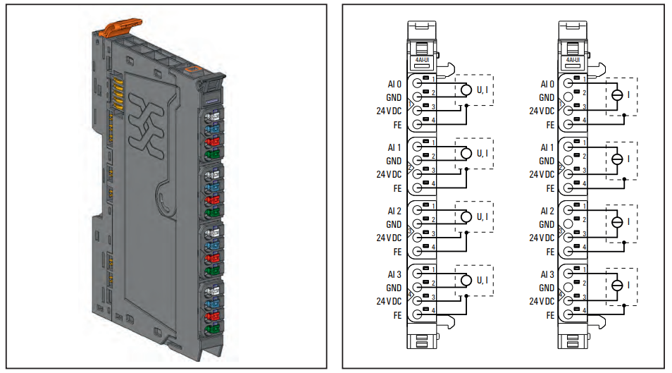
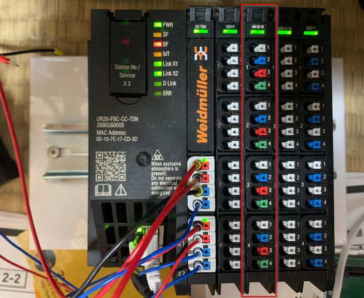
UR20-4AI-UI16
The UR20-4AI-UI-16 analogue input module can be used with the following measuring ranges, which are defined by the parameter settings
- ±10 V、±5 V
- 0 …10V
- ±5V
- 0… 10 V,
- 0 … 5 V,
- 2 … 10 V
- 1 … 5 V
- 0 … 20 mA
- 4 … 20 mA。分解能は
To be aware, the input is protected against voltage surges and overcurrents, but voltages above 30 V can cause module breakdown.
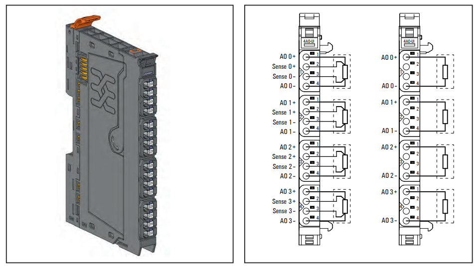
UR20-4AO-UI-16
The analogue output module UR20-4AO-UI-16 can control up to four analogue actuators, defined by parameter settings.
- 0 …10 V
- 0 … 5 V
- 2 … 10 V
- 1 … 5 V
- 0 … 20 mA
- 4 … 20 mA。
Resolution is 16 bits per channel. Actuators can be connected to each connector with 2 or 4 wires and internal switching is automatic.
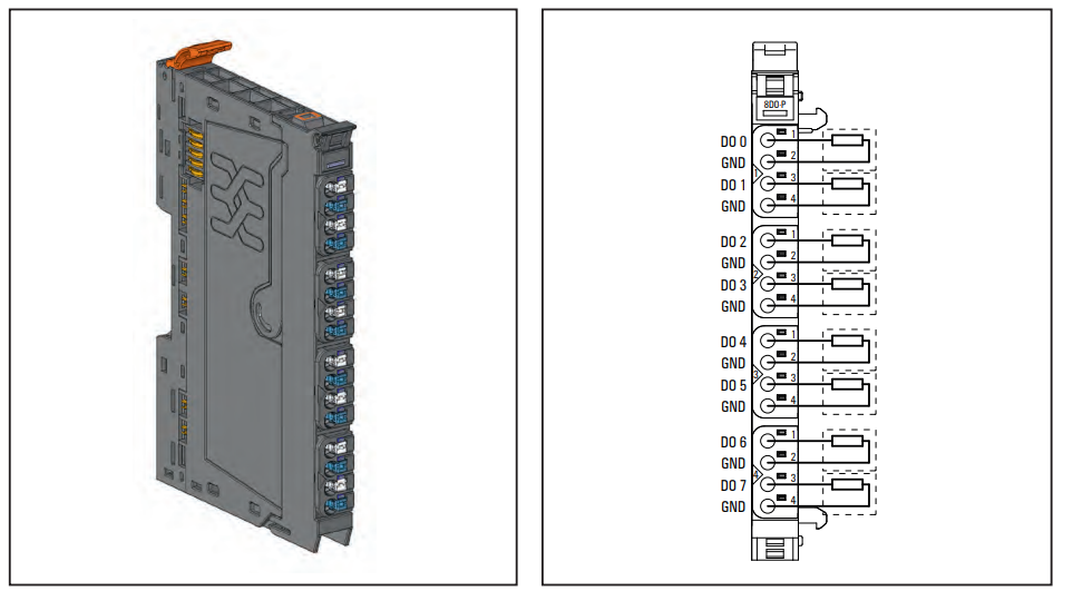
UR20-8DO-P
The UR20-8DO-P digital output module can control up to eight actuators at up to 0.5 A each. The actuators can be connected to each connector with a 2-wire connection and are assigned a status LED. The outputs are powered by the output current path (IOUT).
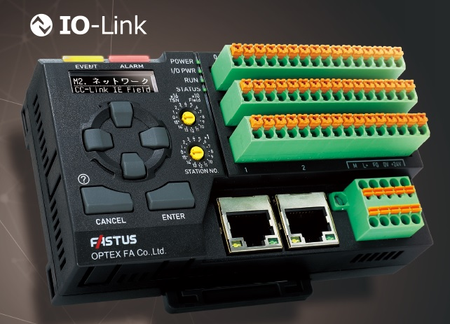
UR-MS16DT
UR-MS16DT] is a high-performance IO-Link master developed by OPTEX for Industrial Ethernet, enabling mixed connection of digital sink (NPN)/source (PNP) 16-channel input/output devices in a single unit. (Minimum cycle time 0.3 ms).
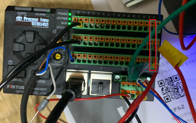
Startup..
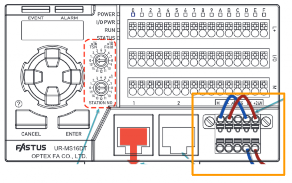
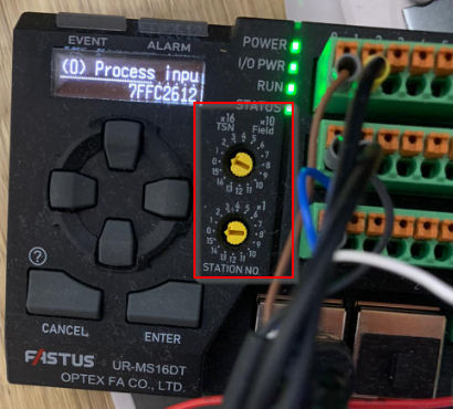
This is the main unit of the UR-MS16-DT.
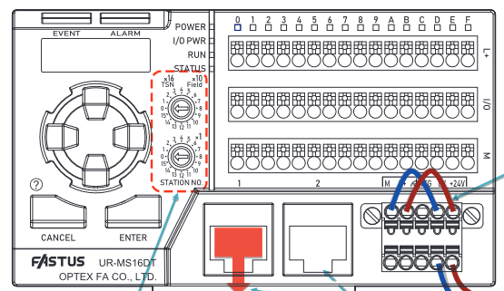
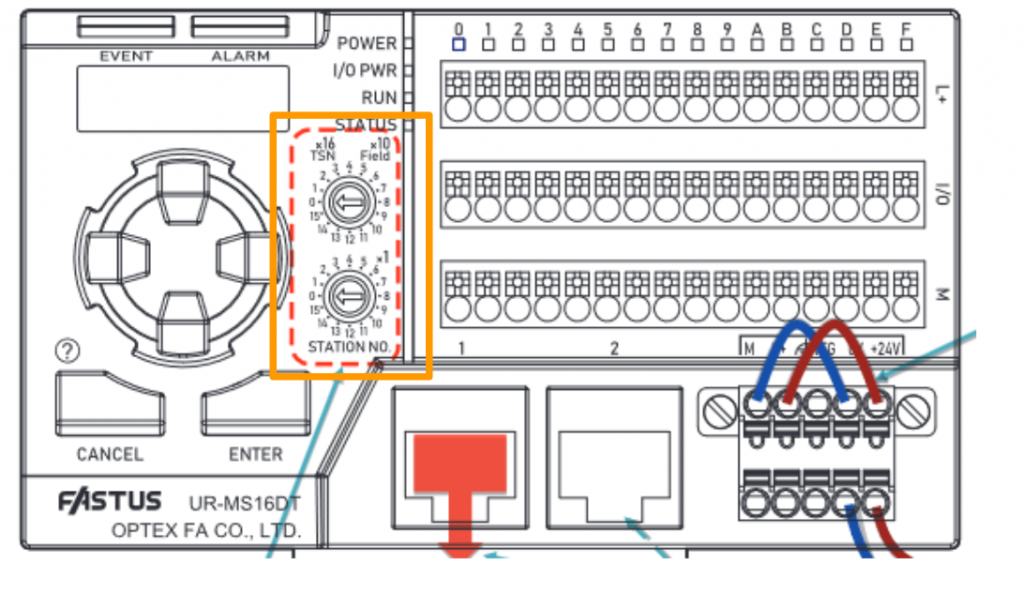
Station Number
Before switching on the power, connect a CC-Link IE Field or CC-Link IE TSN unit and set the station number (Station No.) to the rotary switch.
Connect the LAN Cable
Connect the Ethernet cable to the master station of CC-Link IE Field or CC-Link IE TSN. Can be connected to either the left or right side.
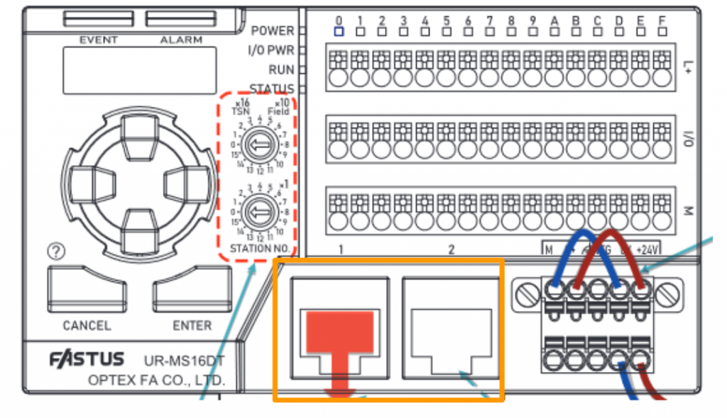
Connect the Power
Connect unit power (+24 V, 0 V) and I/O power (L+, M) in parallel.
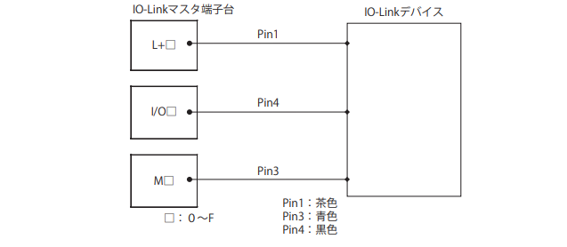
Wiring‐IO Link Master
This is a wiring diagram of the UR-MS16-DT terminals and IO-LINK devices.
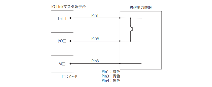
Wiring-PNP Output
This is a wiring diagram of the UR-MS16-DT terminals and the PNP digital output device.
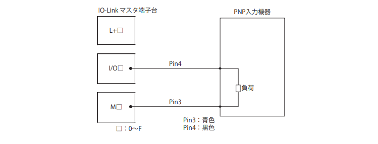
Wiring-PNP Input
This is a wiring diagram of the UR-MS16-DT terminals and PNP digital input devices.
Implementation
Download CSP
Download the CSP File for weidmuelle’s UR20-FBC-CC-TSN Coupler and UR-MS16-DT from the link below.
https://mdcop.weidmueller.com/mediadelivery/asset/900_213743
https://www.cc-link.org/sch/C020?langSeqNo=2&CL=2&prodId=PD2020121396
Module Configuration
Add the RJ71GN11-T2 used in this project from Module Configuration.
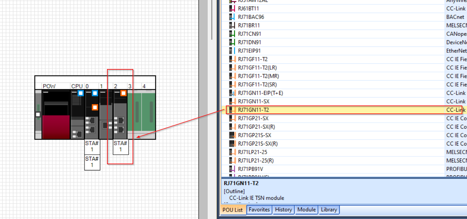
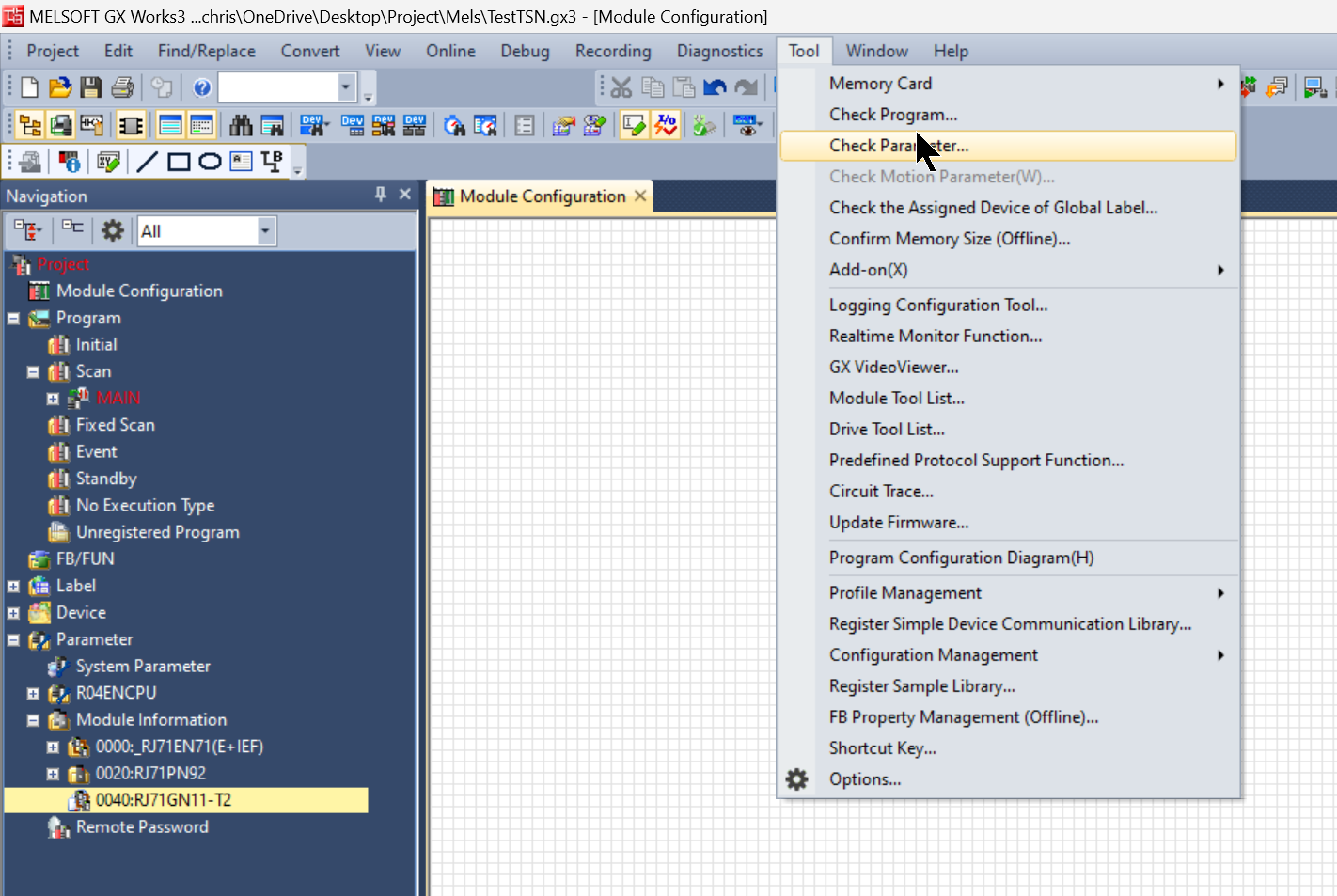
Tool>Check Parameter to check the parameters.
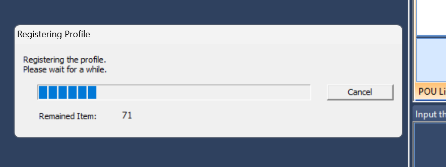
Register Profile
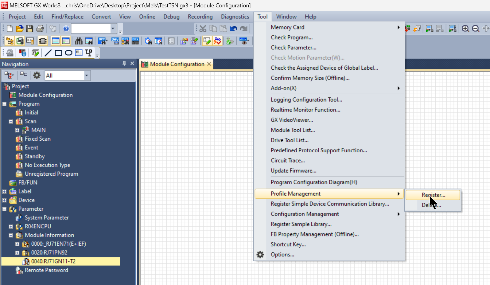
To use CC-Link TSN, it is convenient to register GXWORKS3 in the CSP File from the manufacturer’s website: click Tool>Profile Management>Register.
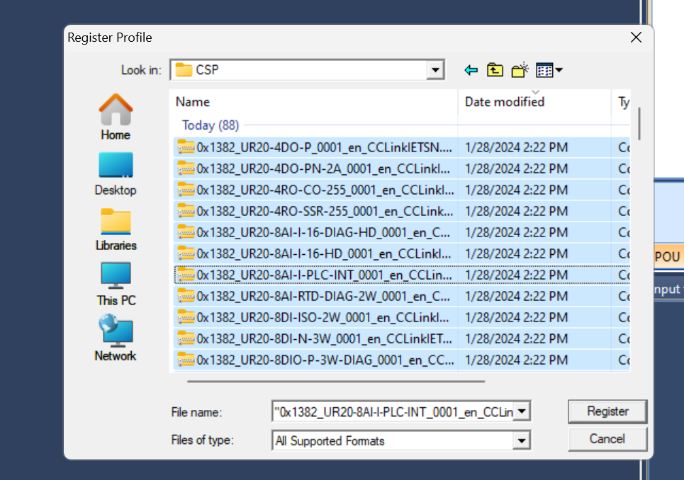
Register the CSP File you have just downloaded from weidmueller and OPTEX HP.
Just a second…
Done!
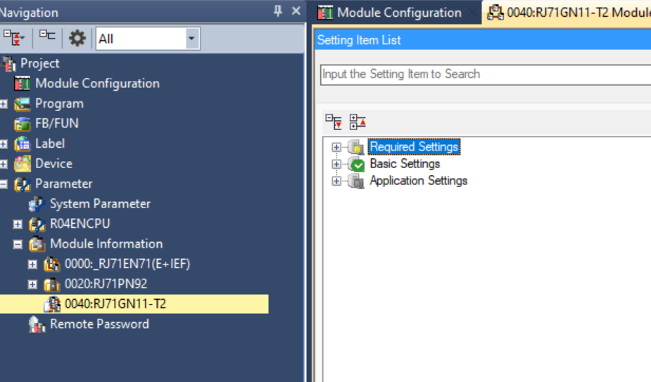
Configuration
Next, click on Parameter>Module Information>RJ71GN11-T2 to configure the basic settings for the RJ71GN11-T2 used in this article.
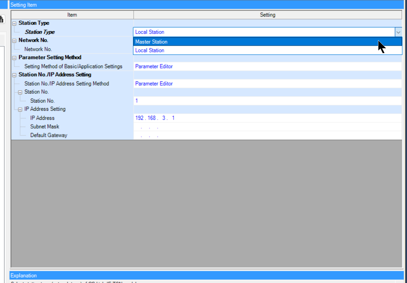
This is the basic settings screen of the RJ71GN11-T2.
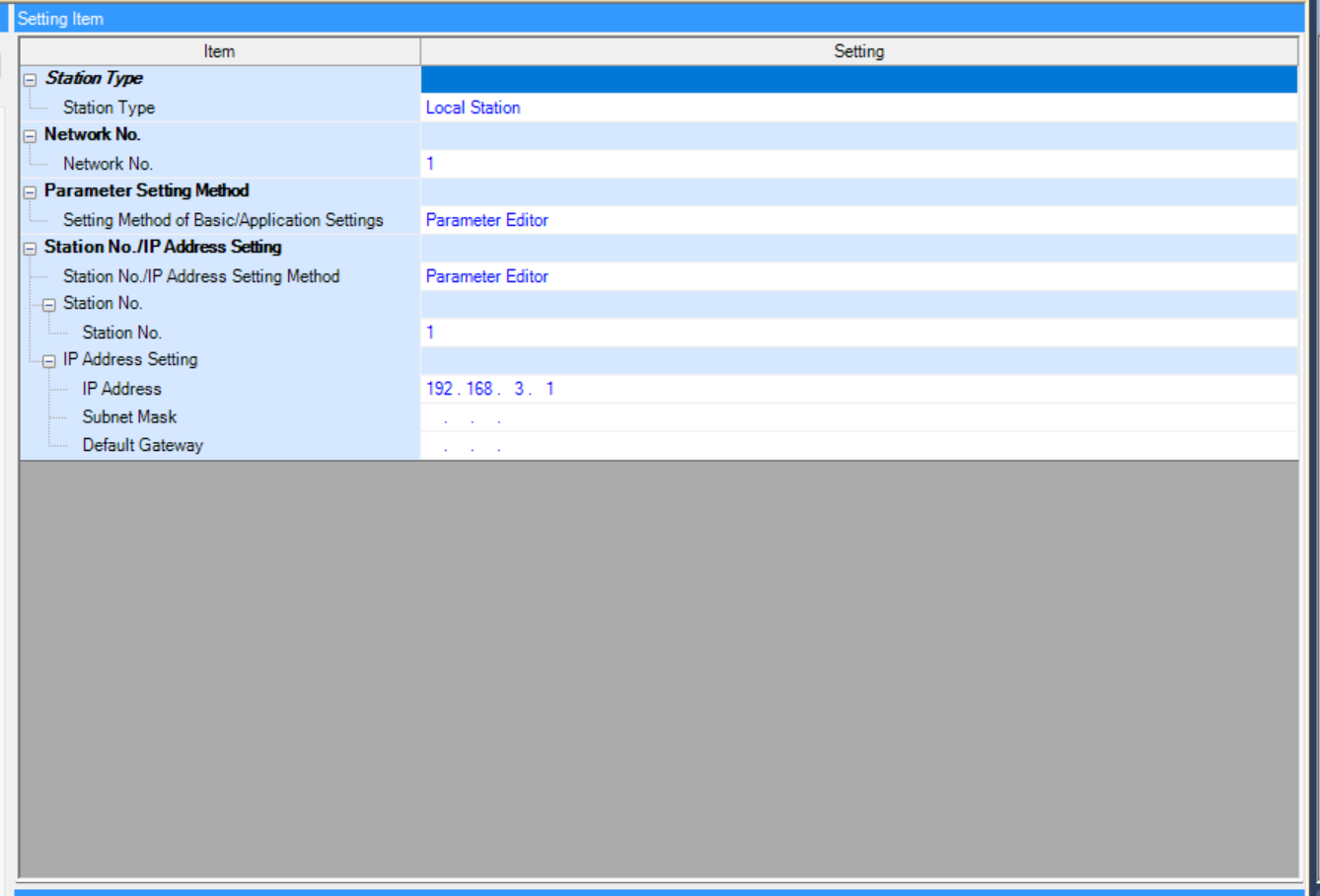
Station Type
This time the RJ71GN11-T2 will be connected to another company’s CCLINK TSN Slave as a Master Station, so set the Station Type to Master Station.
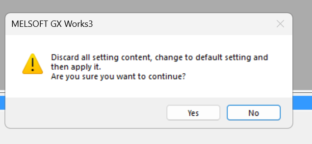
Proceed with Yes.
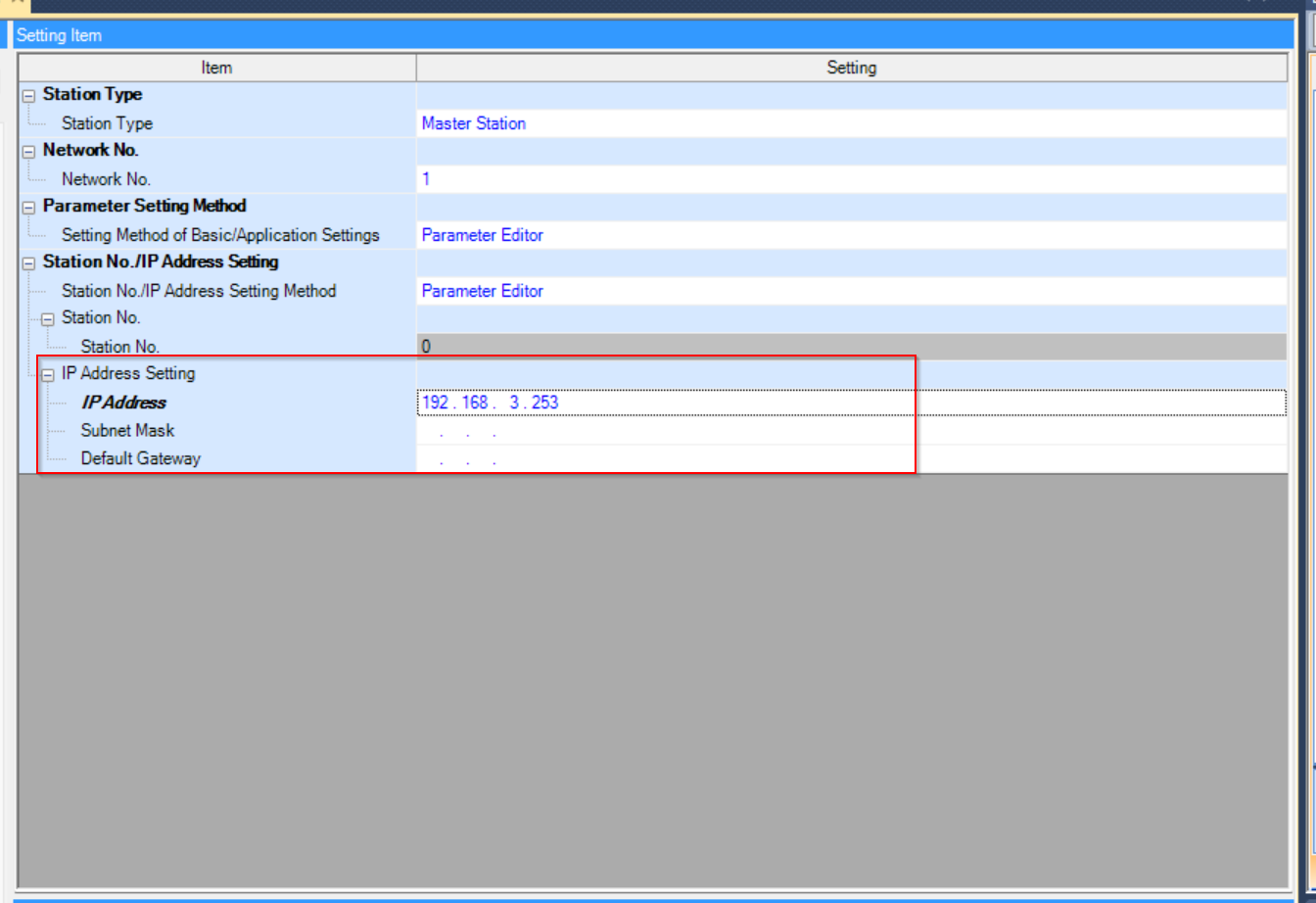
Next, set the IP address of the Master Station.
Network
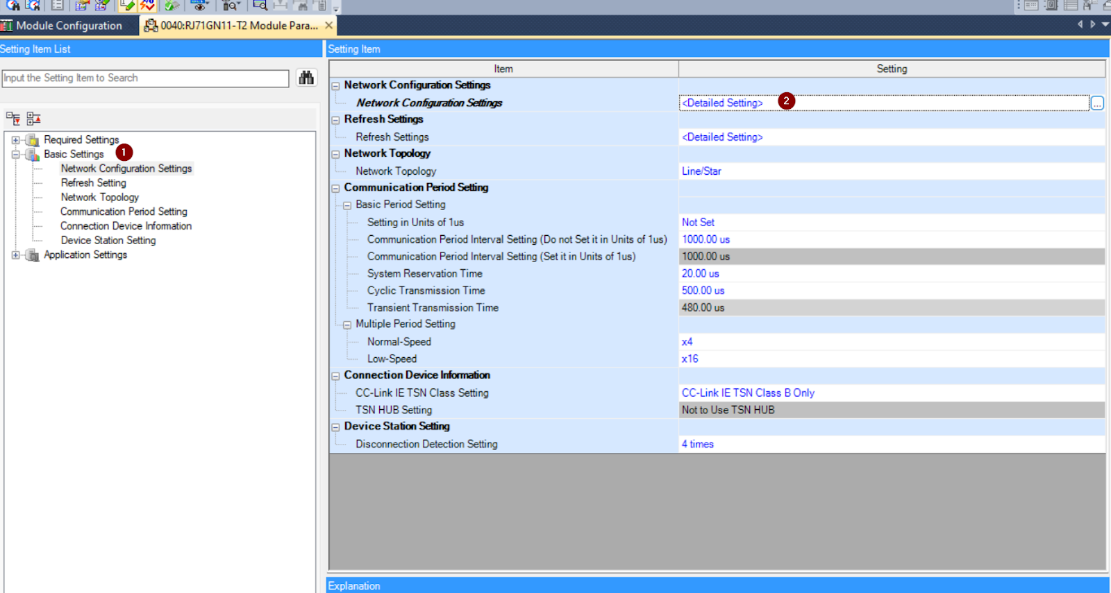
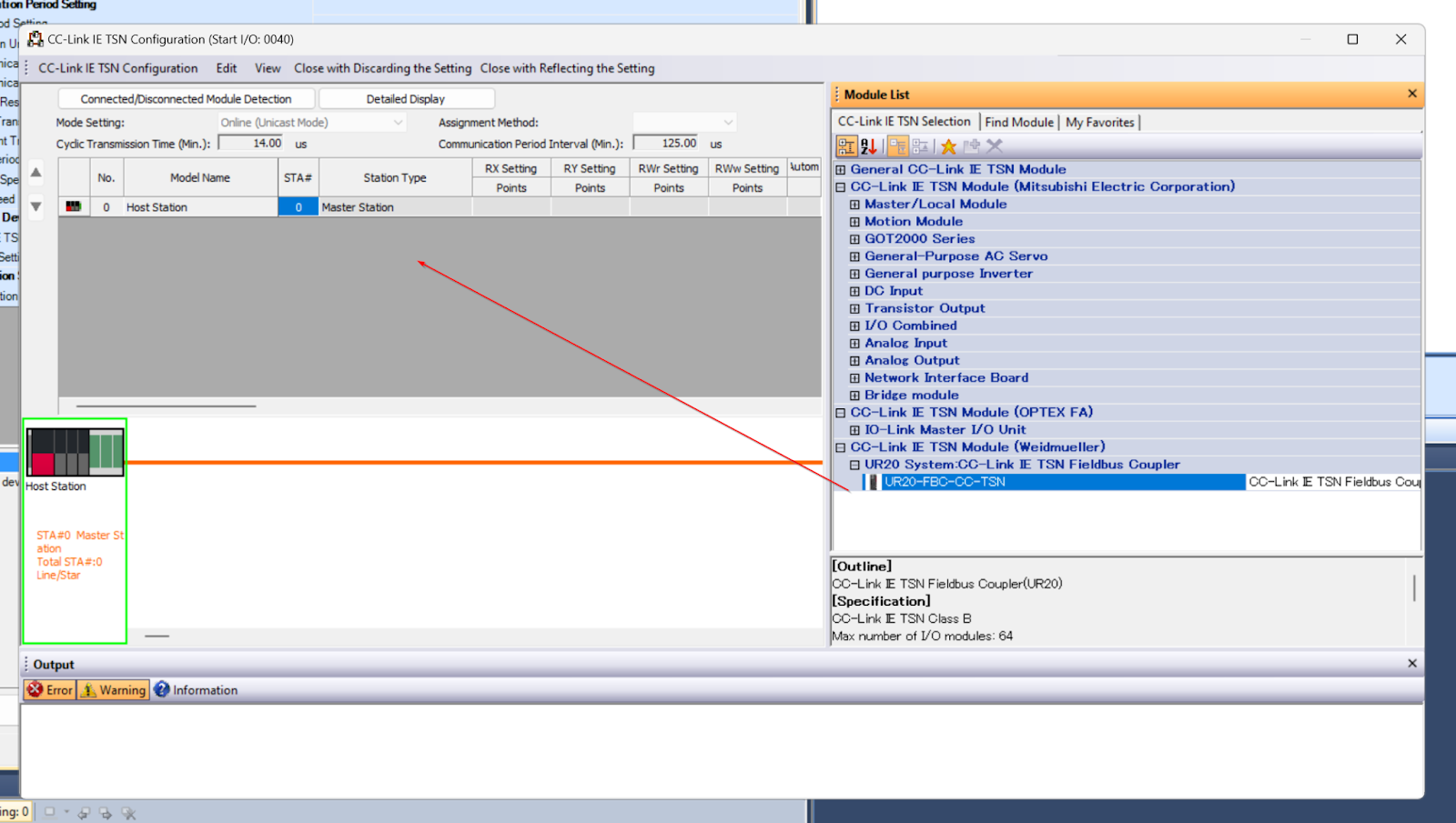
To set up a CCLINK TSN network, open Basic Setting>Network Configuration Settings.
There was a CCLINK TSN Slave that was just registered.
Add UR20-FBC-CC-TSN
DIPSwitch
The TSN Coupler has a DIP switch that allows the IP address of the Coupler to be set.
First add the UR20-FBC-CC-TSN to the network.
Done!
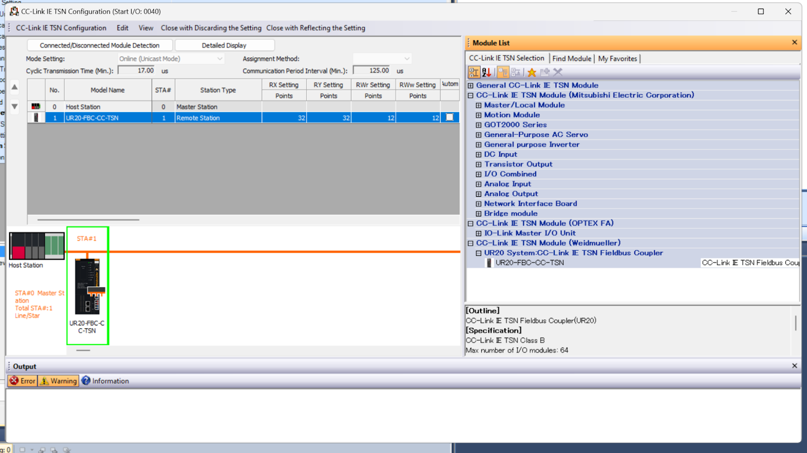
Station
Station numbers should be set according to the application.
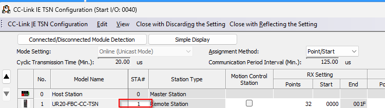
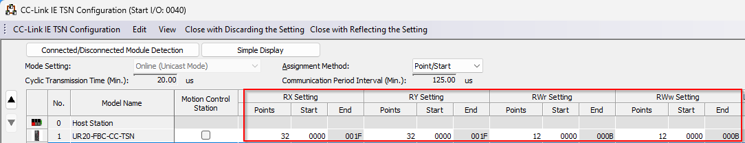
Rx/Ry/Rwr/Rww Setting
Next, set the Process IO number. This number is related to the Reflesh Setting described later.
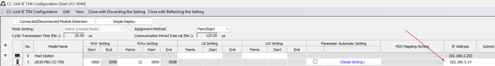
IP Address
For the IP Address, enter the value for which you have just set the DP to the switch.
Configuration
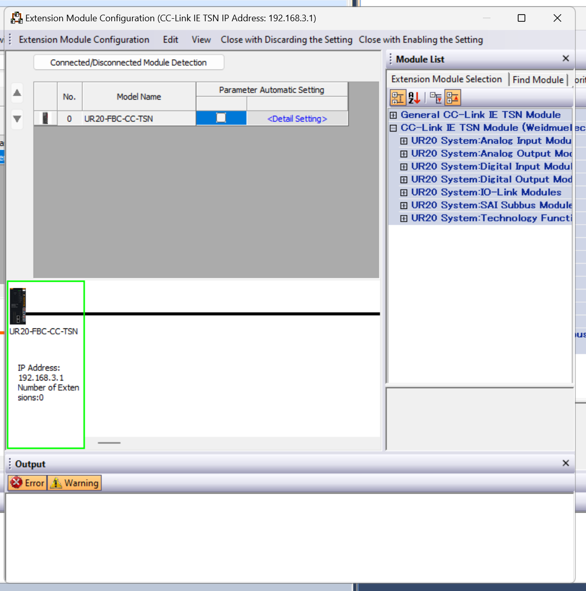
Next, configure the TSN Coupler. Right-click on the UR20-FBC-CC-TSN you have just added>Open Extension Module Configuration.
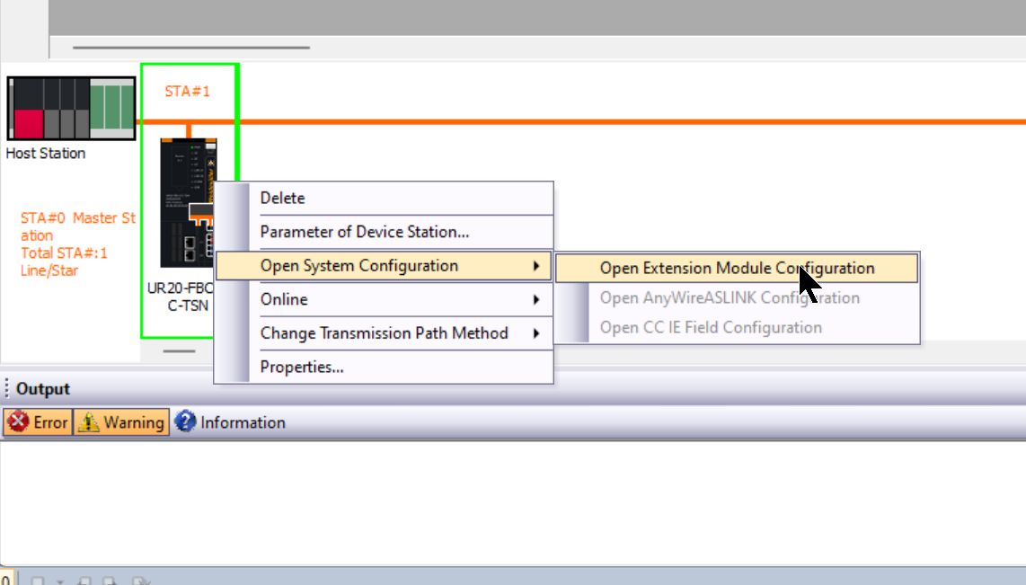
This is the configuration screen of the UR-20-FBC-CC-TSN Coupler.
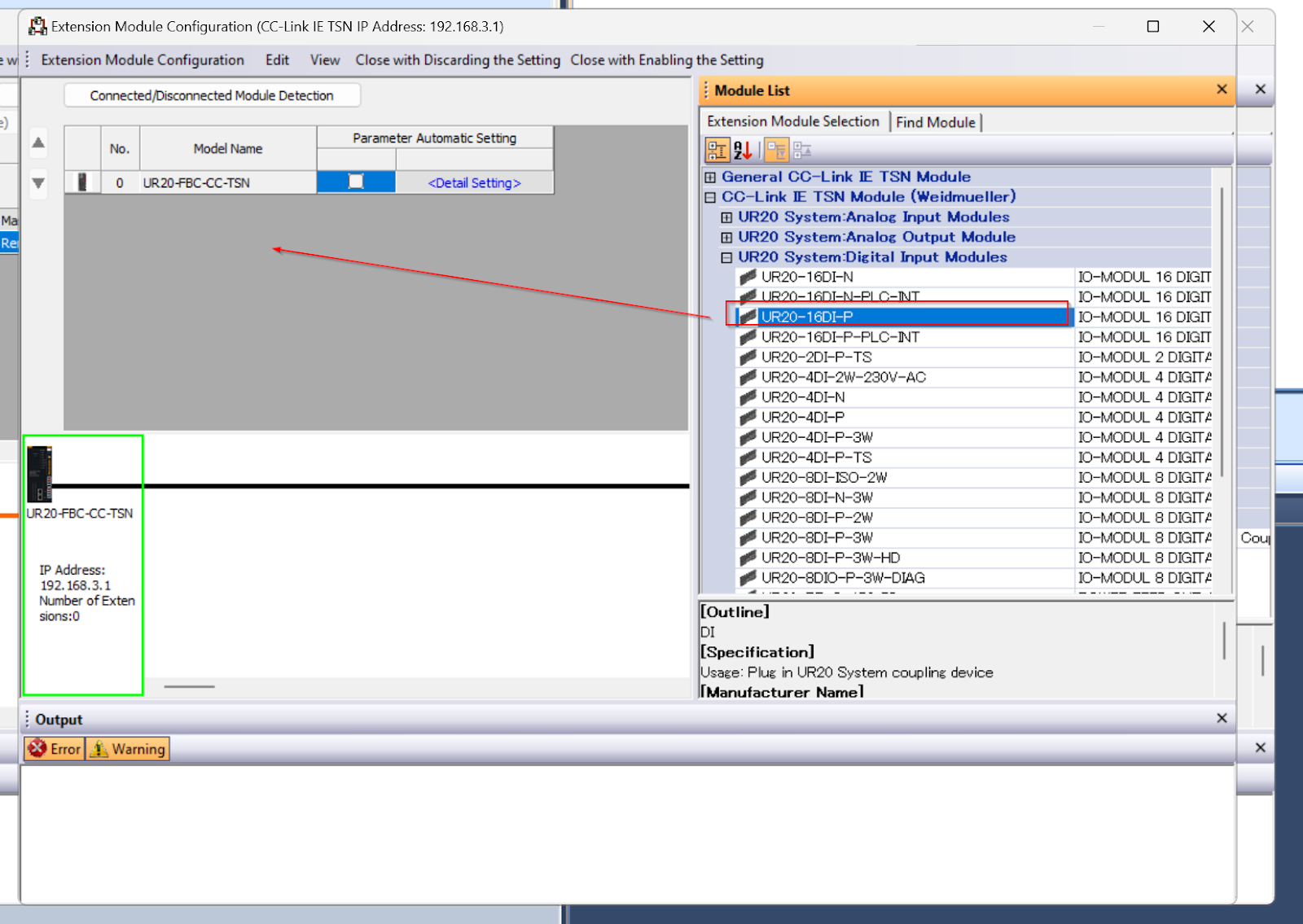
UR20-16DI-P
Add the UR20-16DI-P installed in Slot 1 to Network Configuration.
Drop UR20-16DI-P from the Module List.
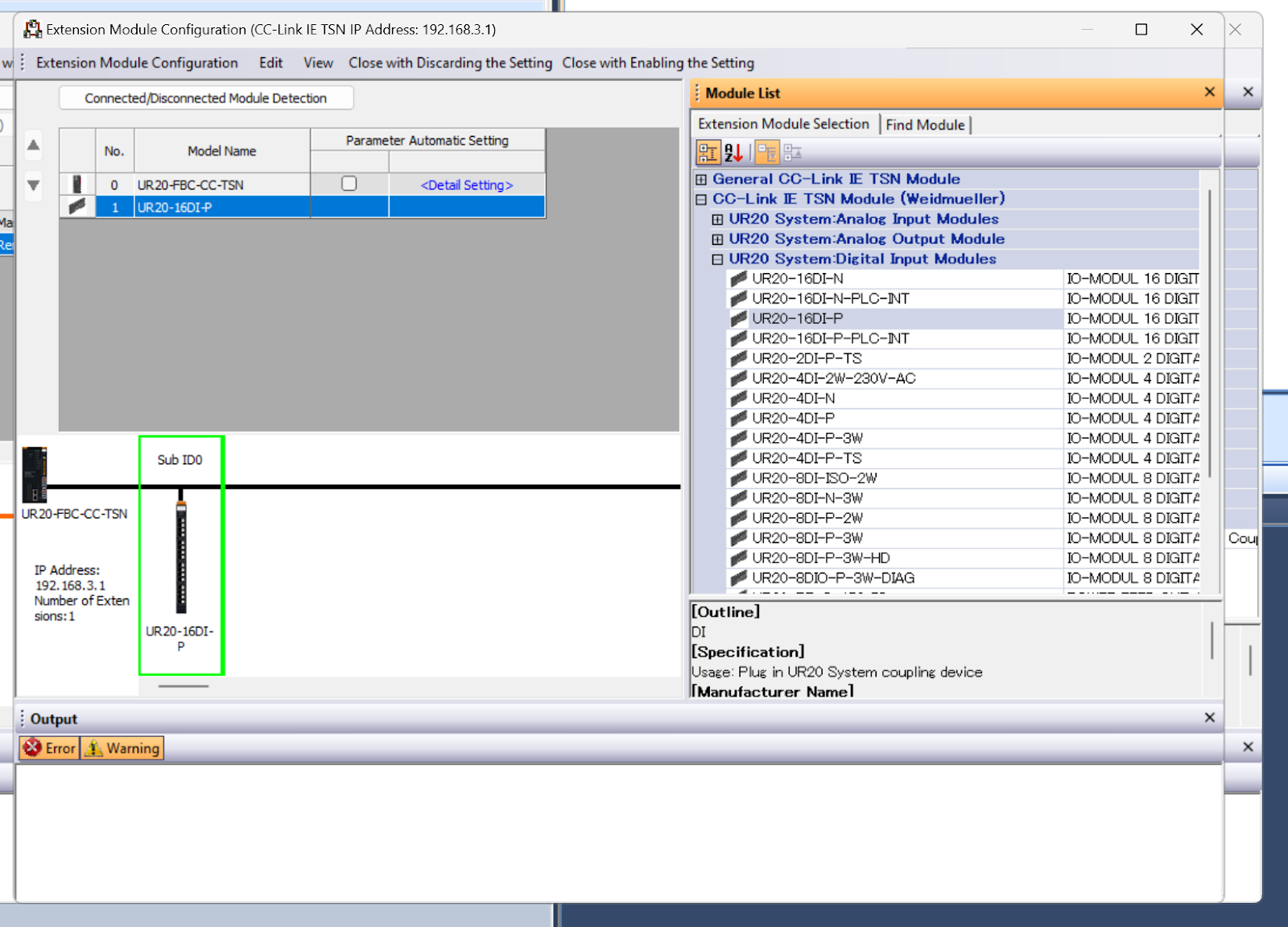
Done!
UR20-4AI-UI-16
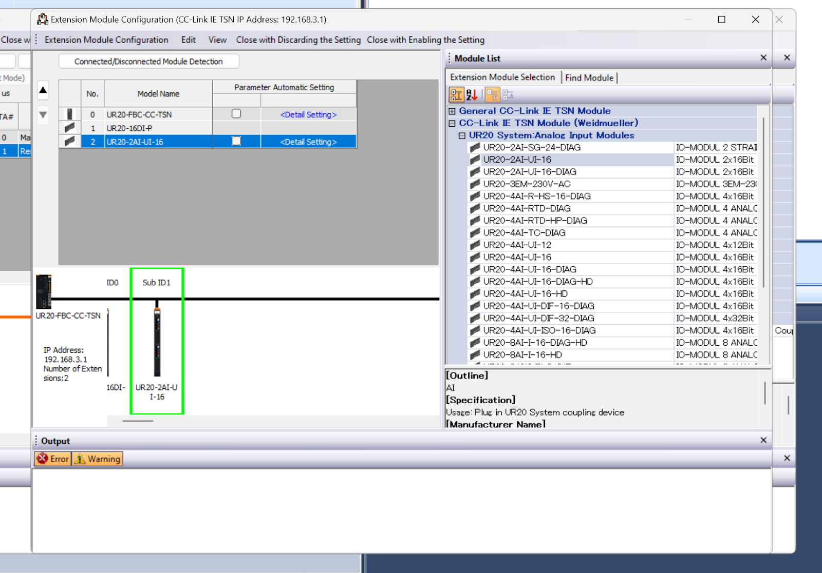
Add the UR20-4AI-UI-16 installed in Slot 2 to Network Configuration.
Drop UR20-4AI-UI-16 from the Module List.
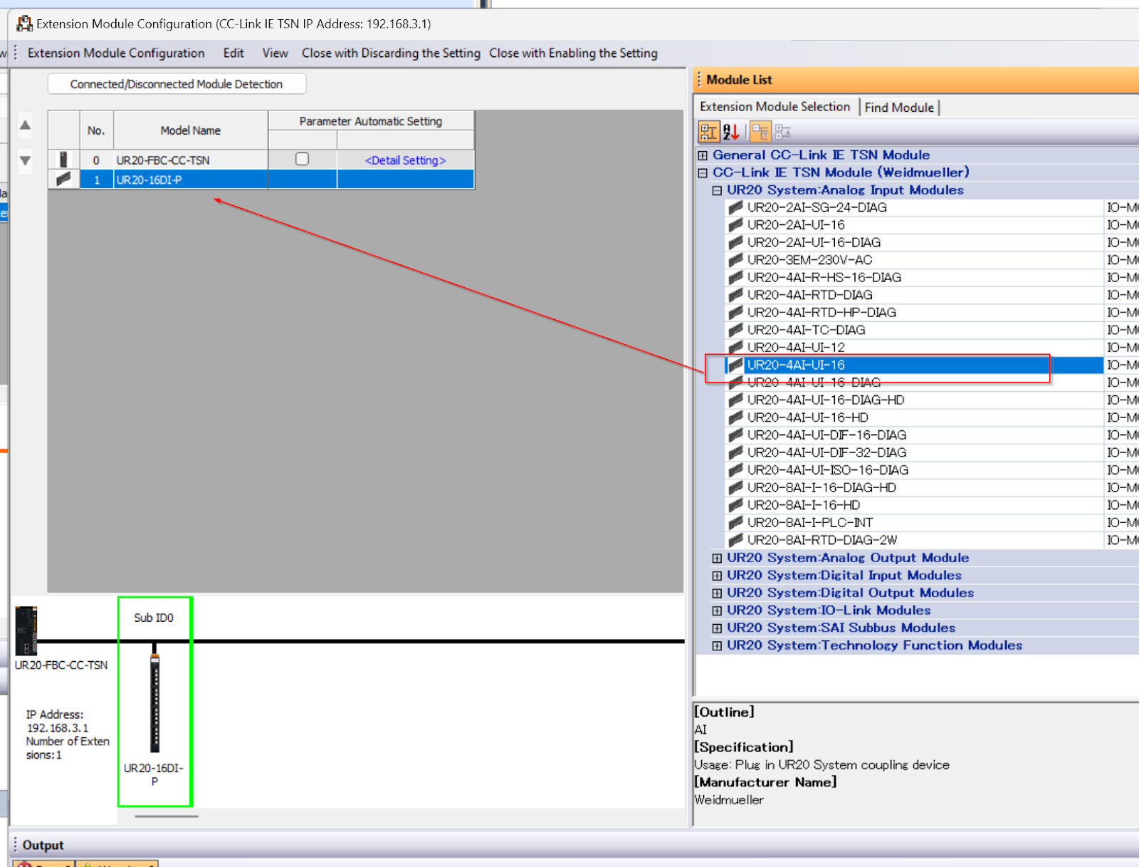
Done!
Next, click <Detail Setting> to configure the UR20-4AI-UI-16.
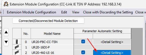
Set the analogue input measurement Range for each Channel.
UR20-4AO-UI-16
Add the UR20-4AI-UI-16 installed in Slot 3 to Network Configuration.
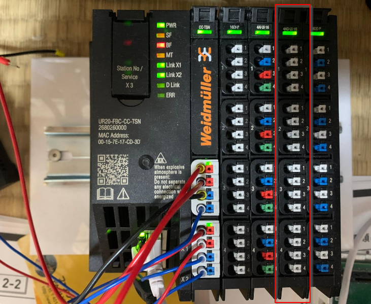
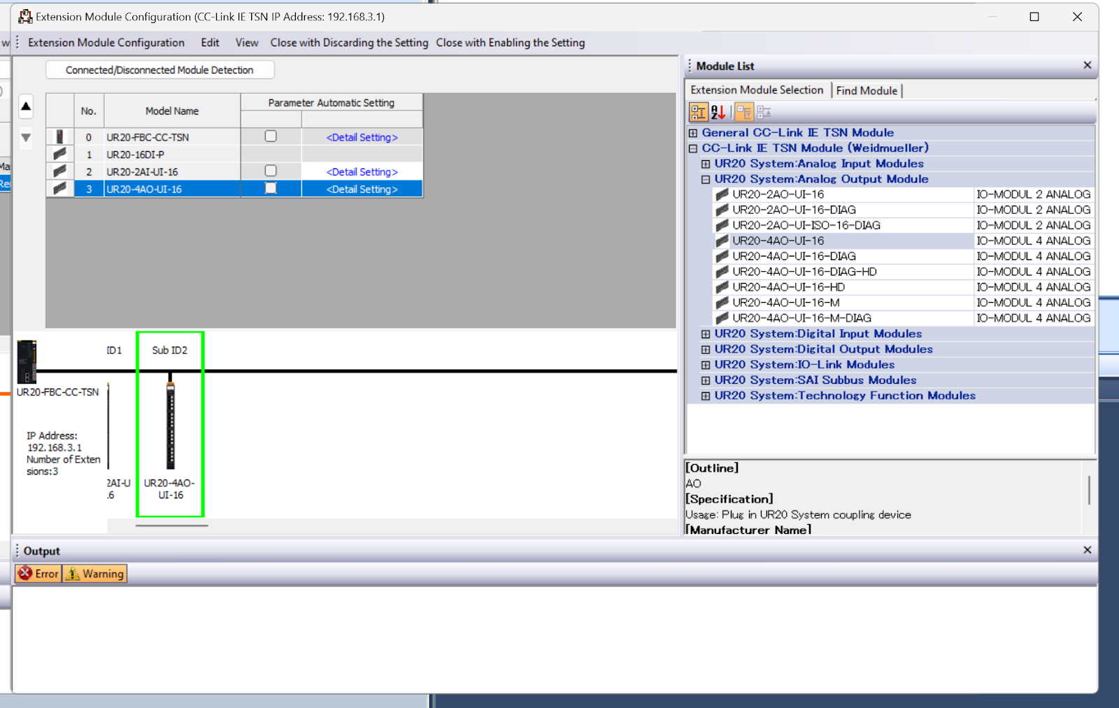
Drop UR20-4AO-UI-16 from the Module List.
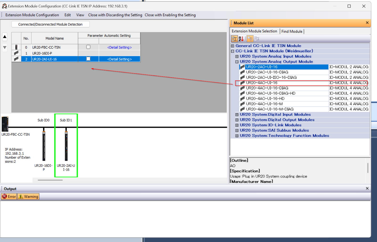
Done!
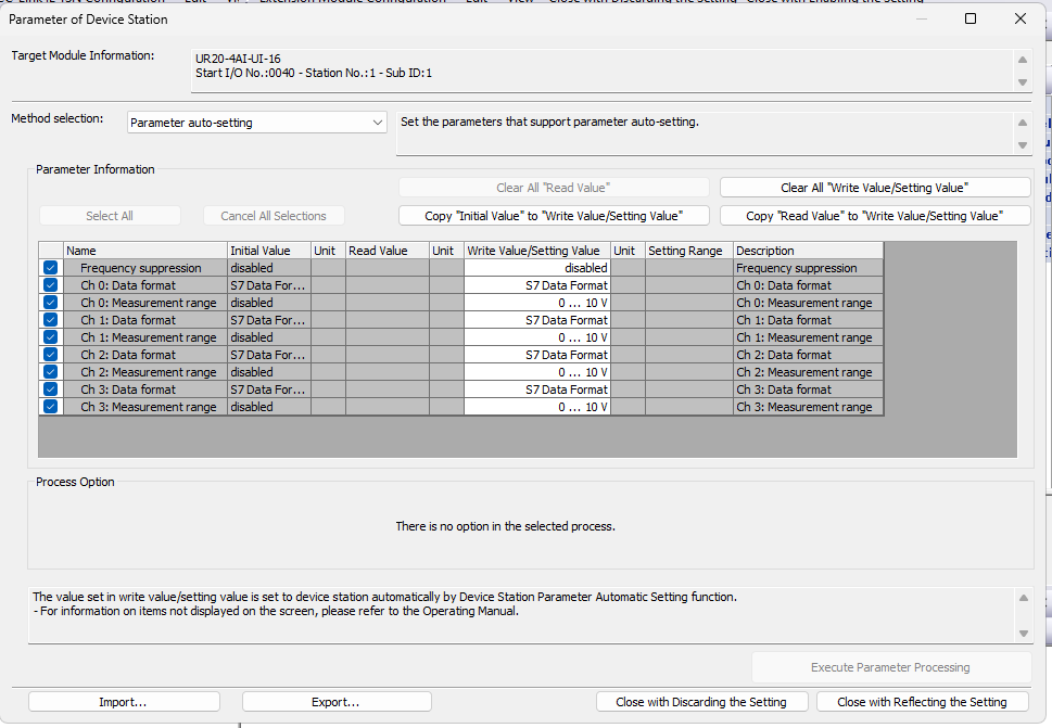
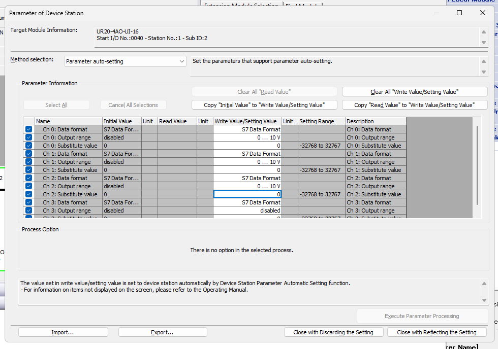
Next, click <Detail Setting> to configure the UR20-4AO-UI-16.
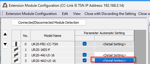
Set the analogue output Range for each Channel.
UR20-8DO-P
Add the UR20-8DO-P installed in Slot 4 to Network Configuration.
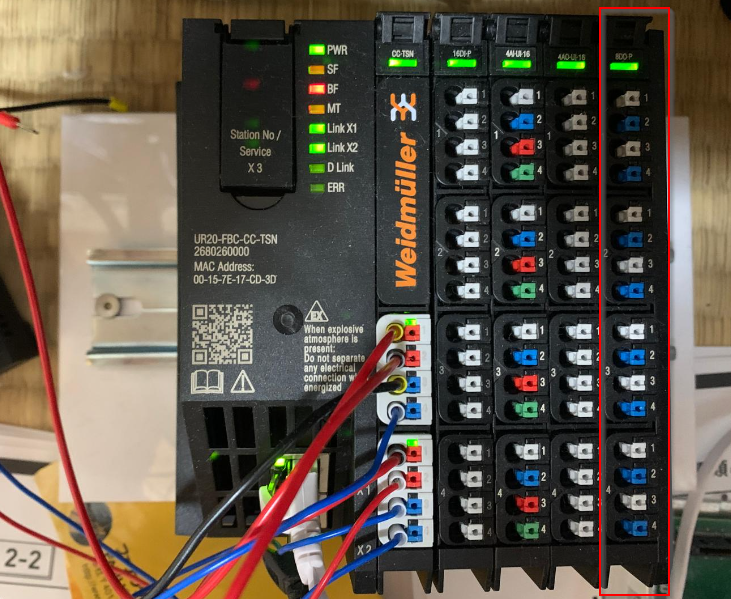
Drop UR20-8DO-P from the Module List.
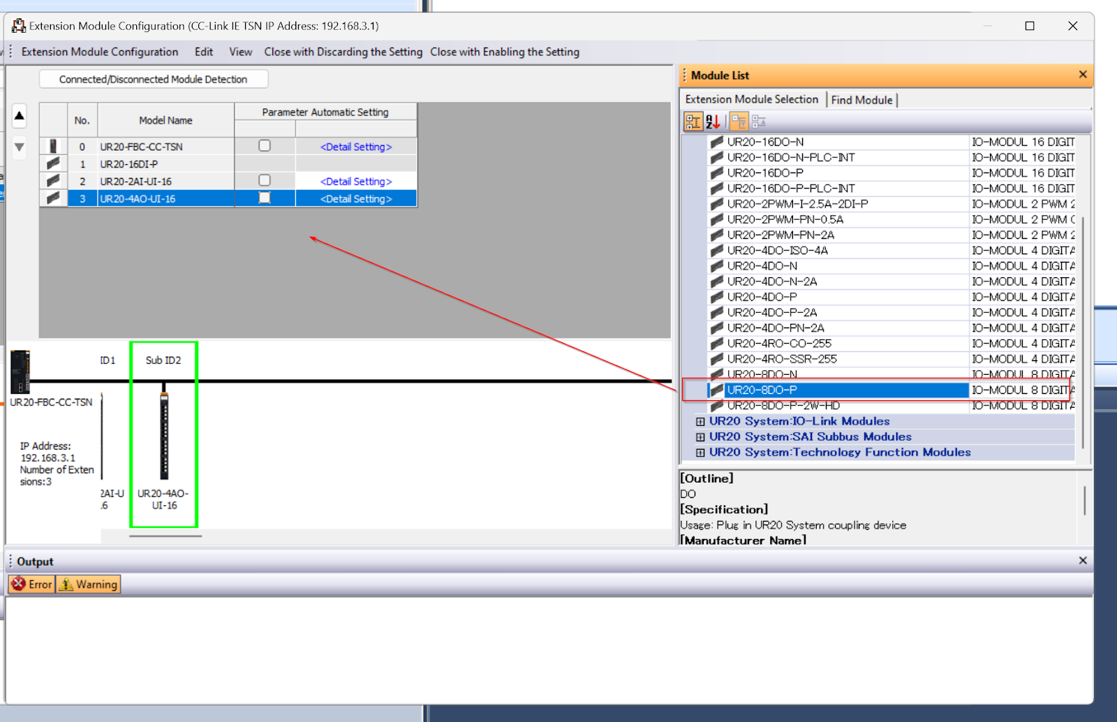
Done!
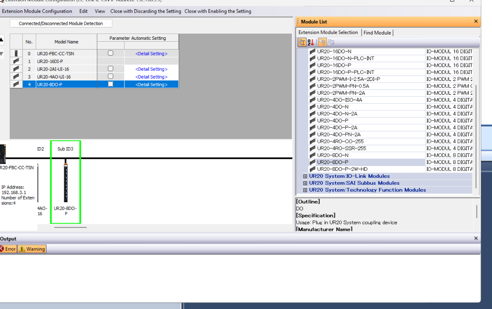
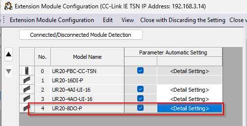
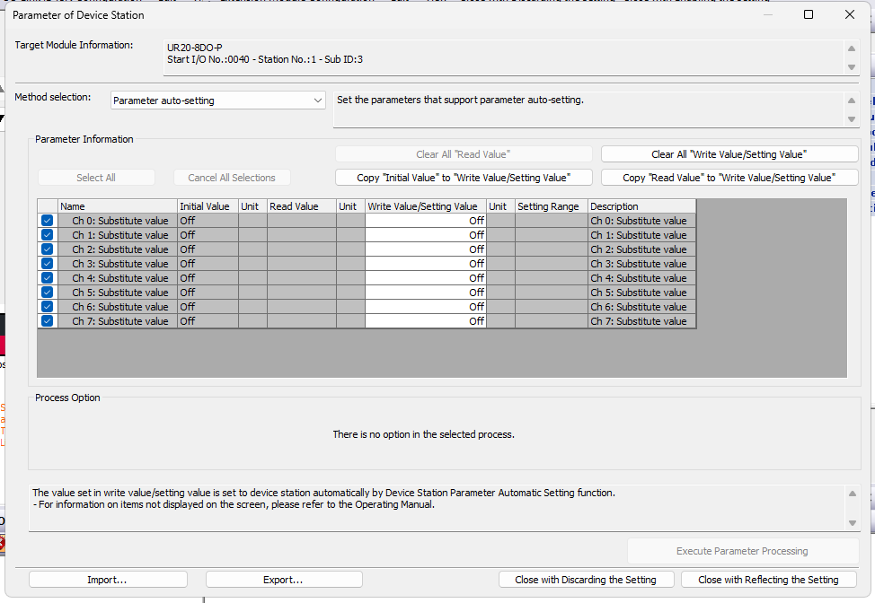
Next, click <Detail Setting> to configure the UR20-8DO-P.
Set what to do with the Fault state of each Channel digital output.
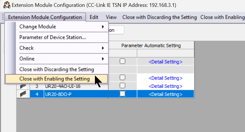
Save Configuration
Finally, save the configuration of the UR20-FBC-CC-TSN under Extension Module Configuration>Cloas with Enabling the Setting.
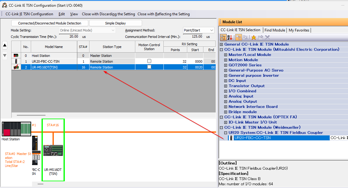
Add UR-MS-16DT(TSN)
Add UR-MS-16DT (TSN) to the network.
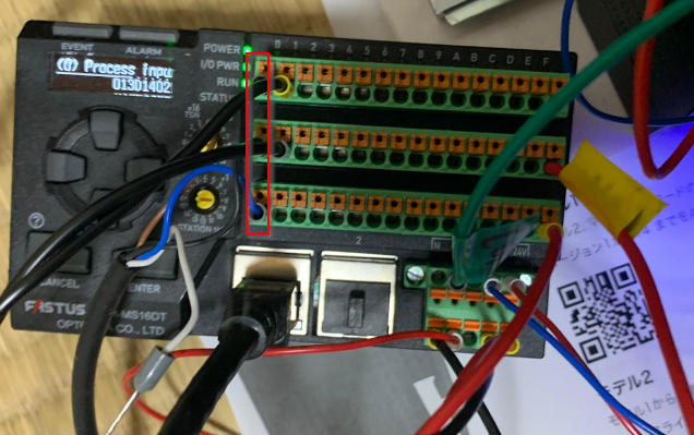
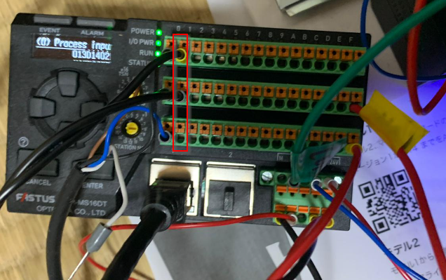
Rotary Switch
The UR-MS-16DT main unit has two rotary switches that allow you to set the Station number of the relevant device. The Station number will also be Y in IP 192.168.X.Y.
So in the diagram below, we have set 16. The IP of that device will be 192.168.3.16.
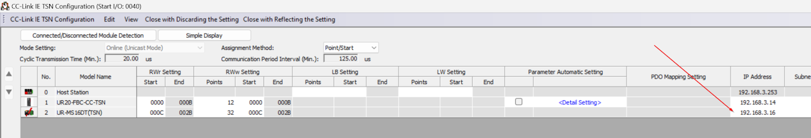
Station/IP Address
The Station number and IP address should be set according to the Rotary switch mentioned earlier.
Configuration
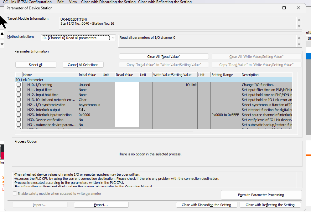
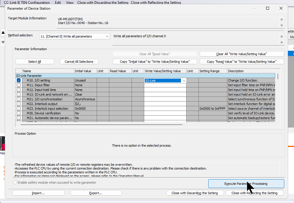
Next, to set the parameters of the UR-MS-16DT (TSN), right-click on the module>Parameter of Device Station.
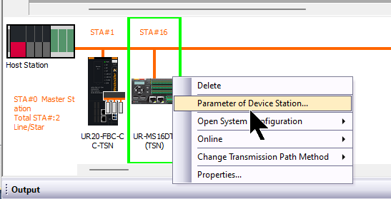
This is the parameter setting screen for UR-MS-16DT (TSN).
Port0
Port 0 of the UR-MS-16DT (TSN) is connected to an OMRON IO-LINK Sensor.
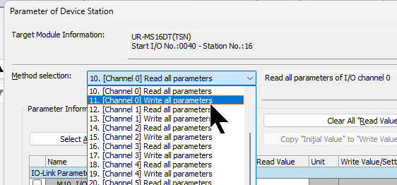
Select 11 [Channel 0] Write all parameters from the Drop-List in Method Selection.
By selecting M10 I/O Setting to IO-Link, Port 0 is used as an IO-Link Port.
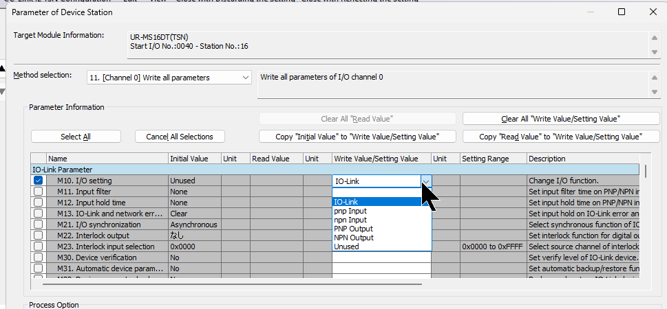
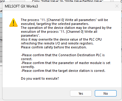
Click Execute Parameter Process to download the parameters to the module.
Proceed with Yes.
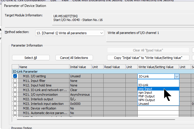
Port1
Port 1 of UR-MS-16DT (TSN) is connected to the switch.
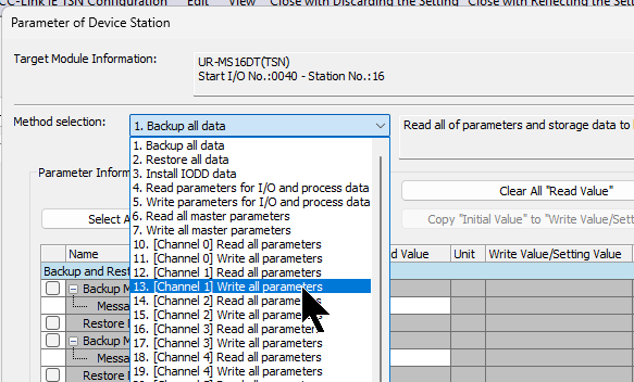
Select 13 [Channel 1] Write all parameters from the Drop-List in Method Selection.
By selecting M10 I/O Setting to PNP Input, Port 0 is used as PNP Input.
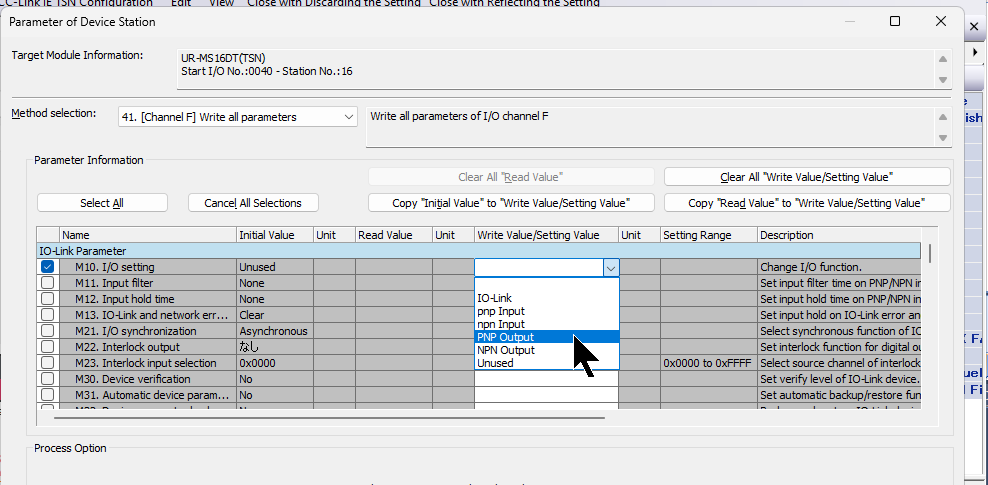
PortF
PortF of the UR-MS-16DT (TSN) is connected to the digital output of the lamp.
Select 41 [Channel F] Write all parameters from the Drop-List in Method Selection.
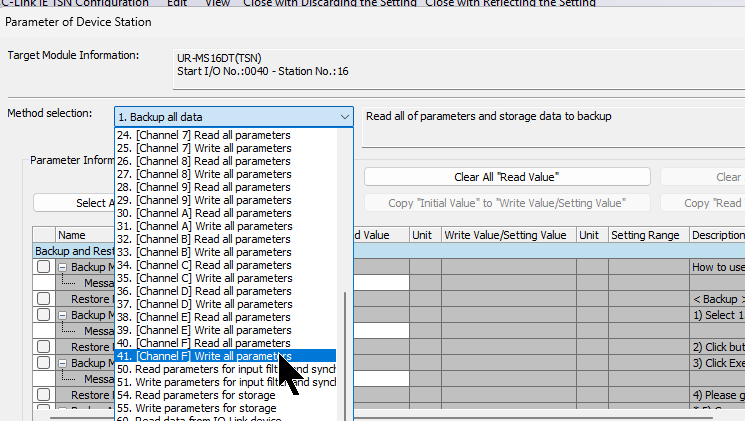
By selecting M10 I/O Setting to PNP Output, Port 0 is used as a PNP Output.
Reflesh
Open Reflashing Setting and set Rx/Ry/RWw/RWr and CPU Internal Mapping.
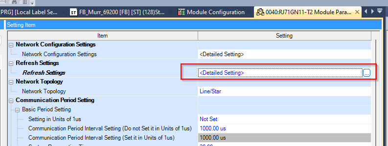
The Reflashing Setting screen appears.
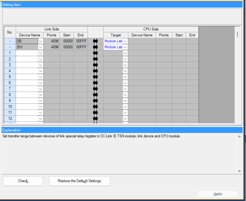
Set it up according to your application.
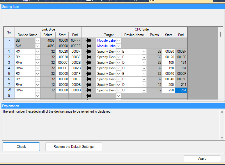
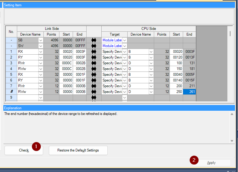
This is the Mapping of the UR-MS16-DT and UR20-FBC-CC-TSN Coupler.
Check the settings with the Check button and save the settings with the Apply button.
Program
The next step is to create a simple programme.
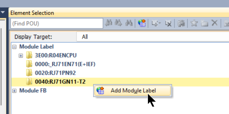
Add Module Label
Add the Rj71GN11-T2 Module label to the project.
MAIN
UR-MS16-DT and UR20-FBC-CC-TSN Coupler Programmes for receiving and transmitting data.
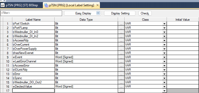
| //UR-MS16DT bPort1Switch:=B21; bPortFLamp:=bPort1Switch; B12F:=bPortFLamp; wEvent.0:=B30; wEvent.1:=B31; wEvent.2:=B32; wEvent.3:=B33; bAccessRdy:=B34; bOverCurrent:=B35; bOverPowerSupply:=B36; bhasNewEvenet:=B37; wLastErrorChannel.0:=B38; wLastErrorChannel.1:=B39; wLastErrorChannel.2:=B3A; wLastErrorChannel.3:=B3B; bAccessError:=B3C; bSysnc:=B3D; bIOLinkRdy:=B3E; bError:=B3F; wDectectValue:=D101; //UR20-FBC-CC-TSN bWeidmuller_DI_In0:=B50; bWeidmuller_DI_In2:=B52; bWeidmuller_DO_Out2:=bWeidmuller_DI_In0 OR (bWeidmuller_DI_In2 AND SM412); B152:=bWeidmuller_DO_Out2; |
Result
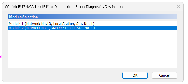
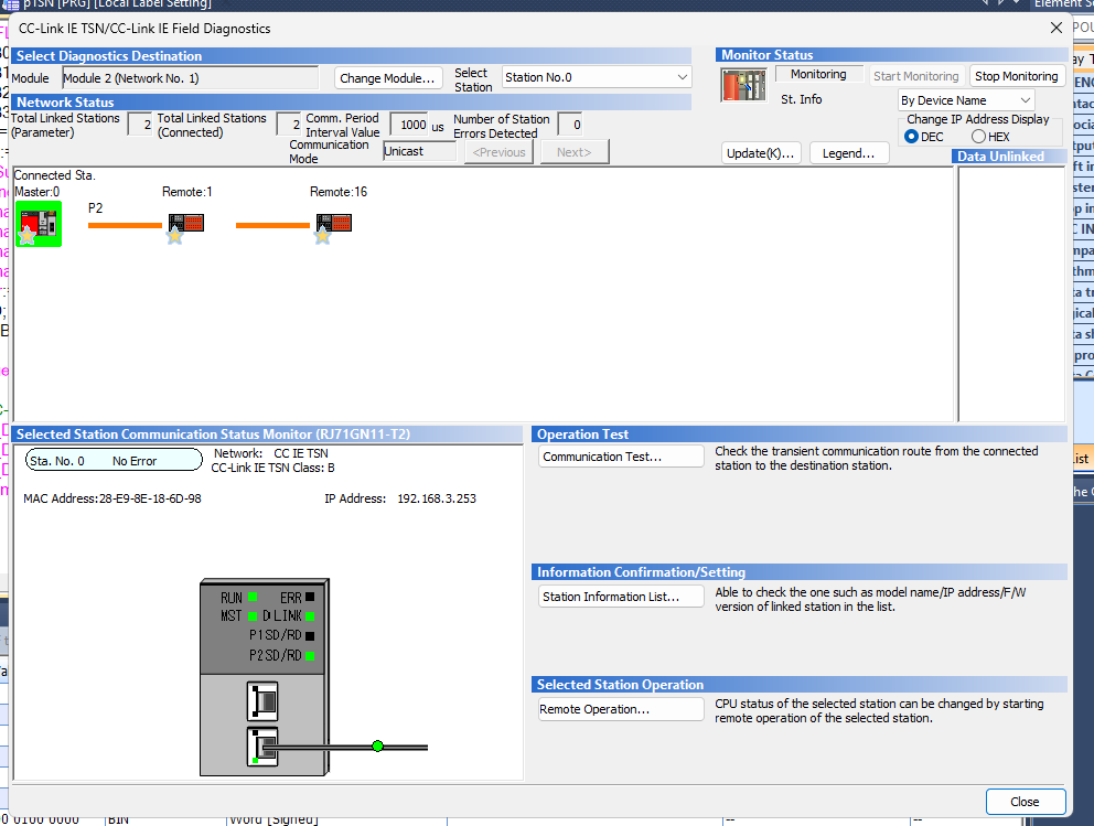
Click Diagnostics>CC-Link IE TSN/CC-Link IE Field Diagnostics to check the network status of the CC-Link IE TSN.
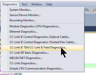
If your project has more than one CC-Link IE network, choose the TSN network.
Done!There are no errors in the TSN network now.
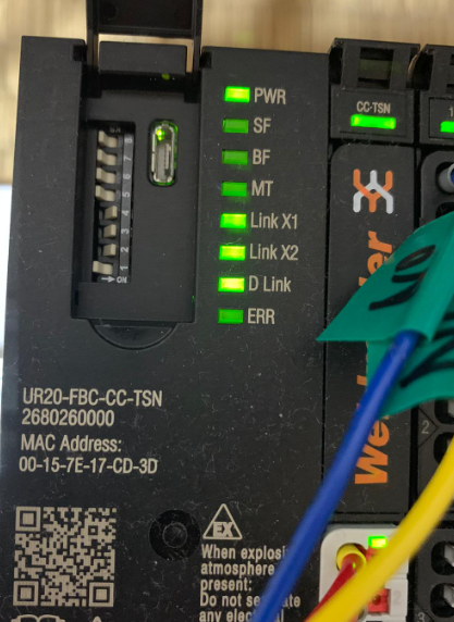
LED status of each Module in normal state.
You can see it in action in this video.