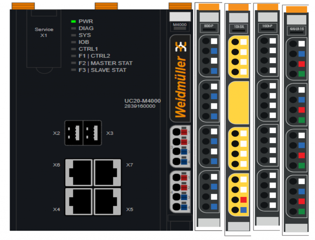
This is the third episode of Weidmüller’s M4000 CPU article, this time in conjunction with Codesys and U-Remote modules. The module UR20-PF-O-1DI-SIL from Weidmüller can also be used to implement safety applications without a safety PLC.
Let’s get started.
Reference Link
UR20-PF-O-1DI-SIL?
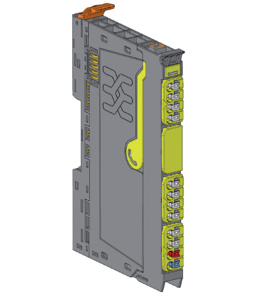
The power feed module UR20-PF-O-1DI-SIL can implement safe feed-in of the output current path. It can be used to monitor two-channel emergency stop command devices and, thanks to its 24 V safe output, can transfer the current status of the output current path to a PLC or switching device (e.g. relay) or can be further cascaded to a u-remote station.
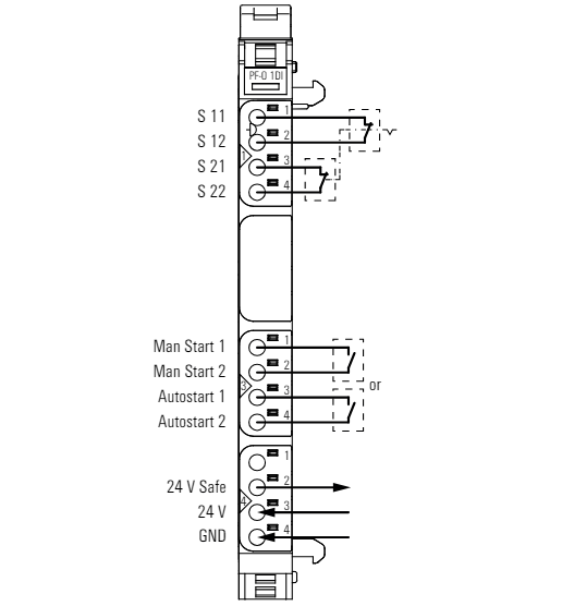
The module must be manually initialized by giving a 0.1-2 s pulse to the “Man Start” input each time the module’s supply voltage is switched on.
The 24 V safe output path is automatically reactivated when the “Autostart” input is used, unless the module supply voltage has been interrupted.
Of course, there is also the ability to evaluate test pulses in safety circuits to detect faults and wiring operations.
Layout
This is the wiring diagram for UR20-PF-O-1DI-SIL.
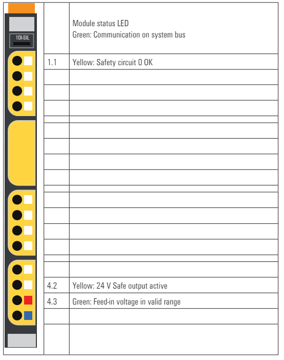
LED
This is the LED meaning of UR20-PF-O-1DI-SIL.
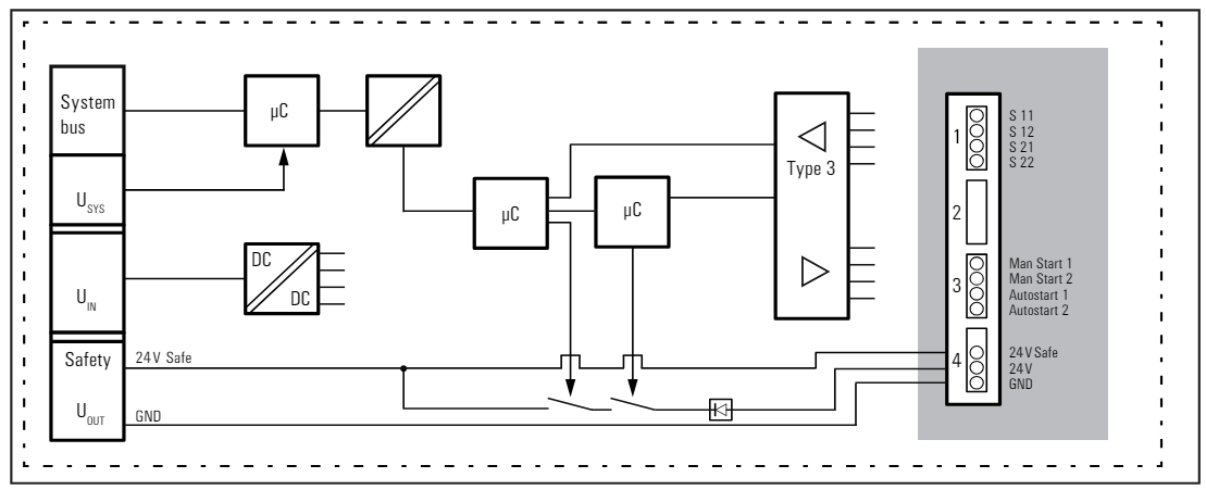
Block Diagram
This is the Block diagram for UR20-PF-O-1DI-SIL. To activate the secure power feed module, follow the sequence below.
- Connect the safety devices to S11 to S22 and disengage (unlock) the devices.
- Connect the 24 VDC power supply to modules 4.3 and 4.4.
- Switch on the u-remote station.
- Operate manual start.
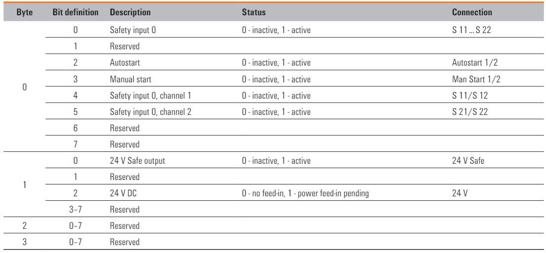
Process Data
This is Process Data for UR20-PF-O-1DI-SIL.
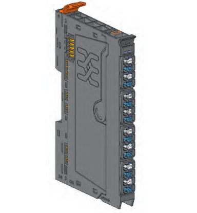
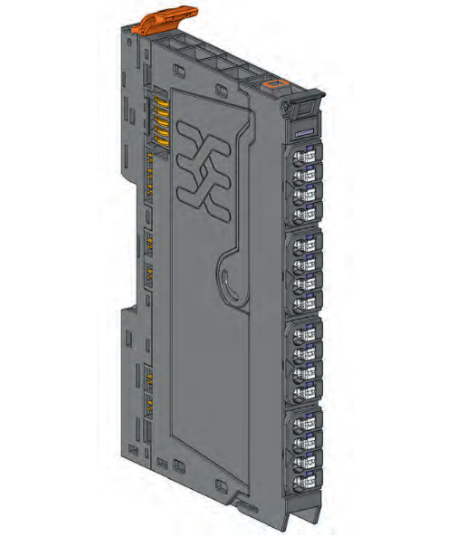
UR20-8DO-P
The UR20-8DO-P digital output module can control up to eight actuators at up to 0.5 A each. Status LEDs are assigned to each channel and the outputs are powered by the output current path (IOUT).
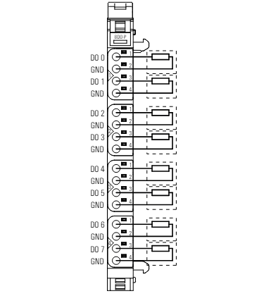
Layout
This is the wiring diagram for the UR20-8DO-P.
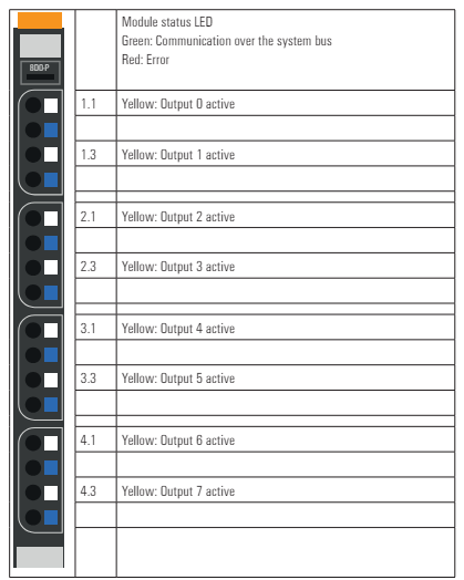
LED
This is the LED meaning of the UR20-8DO-P.
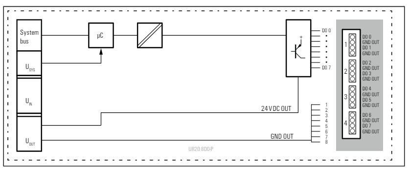
Block Diagram
This is a Block diagram of the UR20-8DO-P.
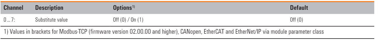
Process Data
This is Process Data for UR20-8DO-P.
UR20‐16DI‐P‐1
The UR20-16DI-P digital input module can detect up to 16 binary control signals. Four sensors can be connected to each connector in a one-wire configuration. In addition, a status LED can be assigned to each channel.
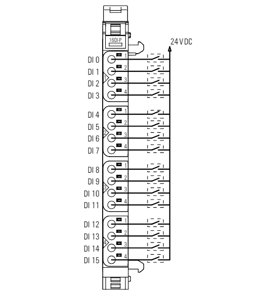
Layout
This is the wiring diagram for the UR20-16DI-P-1.
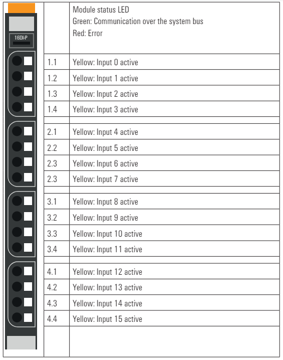
LED
This is the LED meaning of UR20-16DI-P-1.
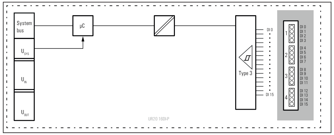
Block Diagram
This is the Block diagram for UR20-16DI-P-1.
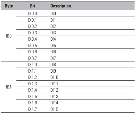
Process Data
This is Process Data for UR20-16DI-P-1.
UR20-4AI-UI-16
The UR20-4AI-UI-16 analogue input module can be configured with the following measurement ranges.
- ±10 V
- ±5 V
- 0 … 10 V
- 0 … 5 V
- 2 … 10 V
- 1 … 5 V
- 0 … 20 mA
- 4 … 20 mA。
Resolution is 16 bits per channel and sensors can be connected to 2-wire, 3-wire and 3-wire +FE. They are also protected against voltage surges and overcurrents.

Layout
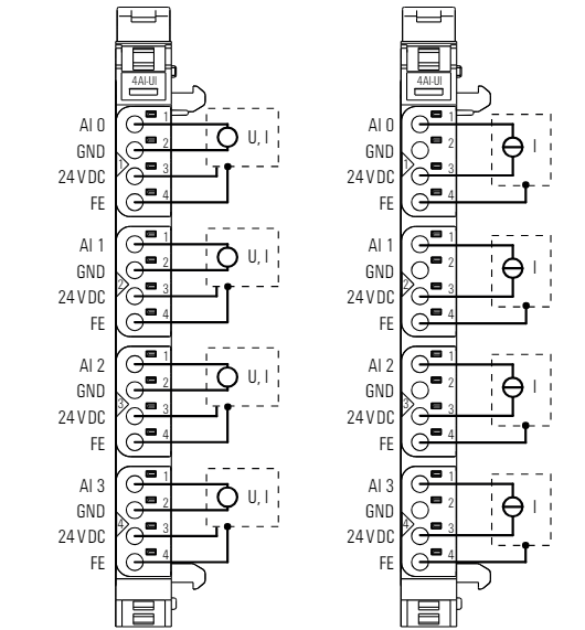
This is the wiring diagram for the UR20-4AI-UI-16.
LED
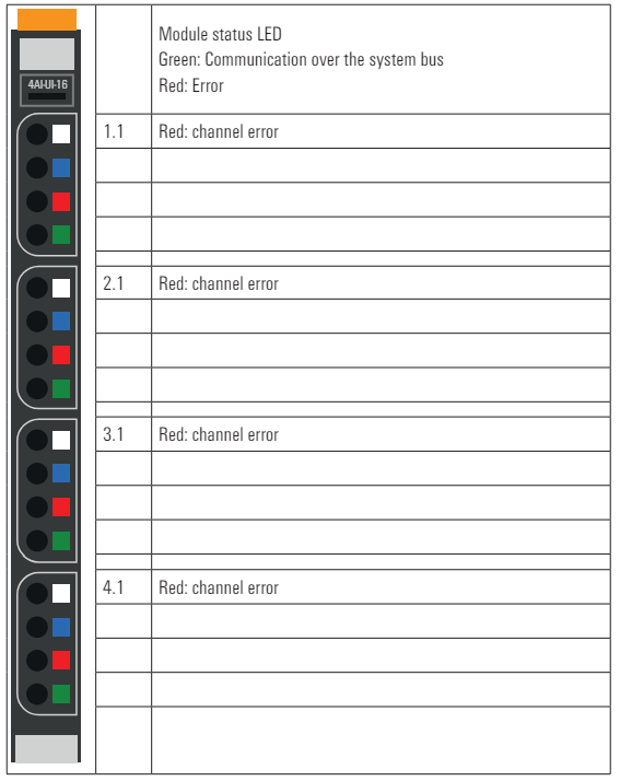
This is the LED meaning of UR20-4AI-UI-16.
Block Diagram
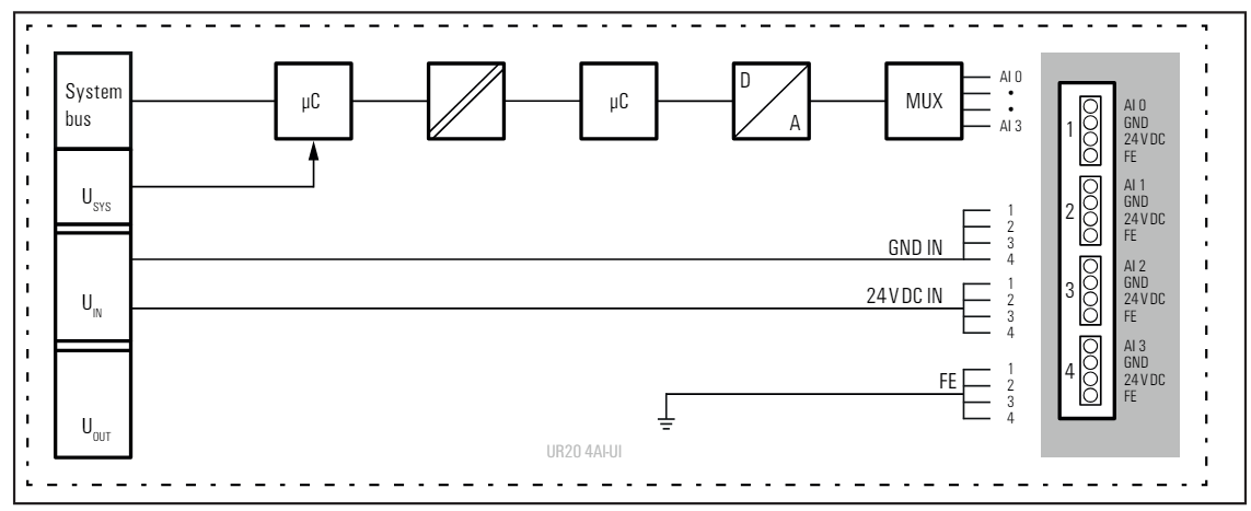
This is the Block diagram for UR20-4AI-UI-16.
Process Data
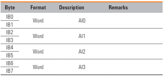
This is Process Data for UR20-4AI-UI-16.
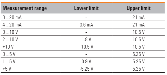
Measurement Range
This is the measurement range of the UR20-4AI-UI-16.
Implementation
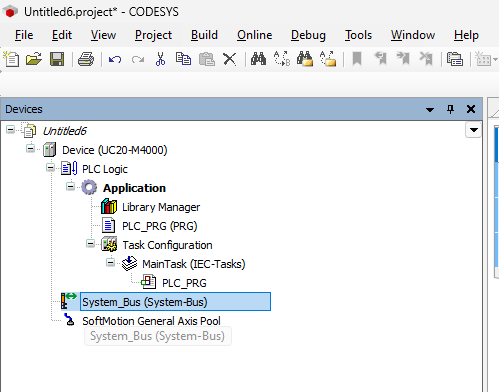
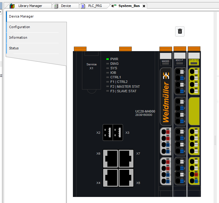
To use Weidmüller modules on the M4000, modules can be added from the System_Bus in Codesys.
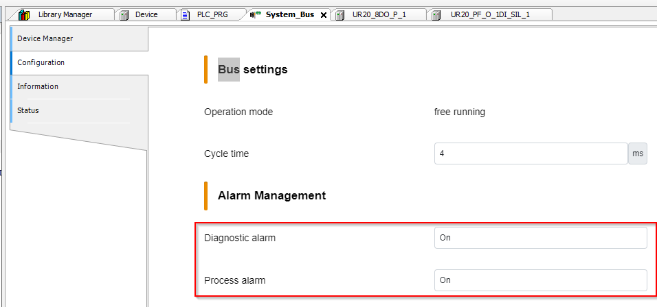
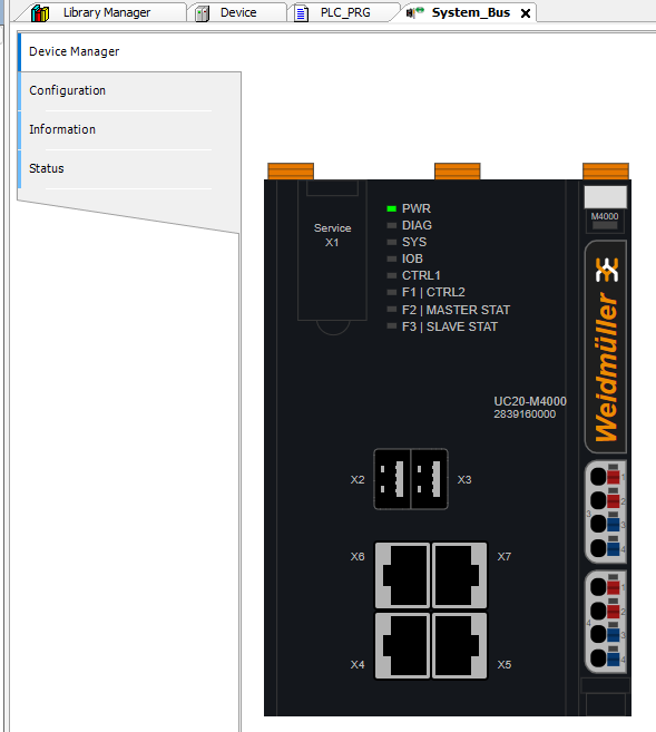
Configuration
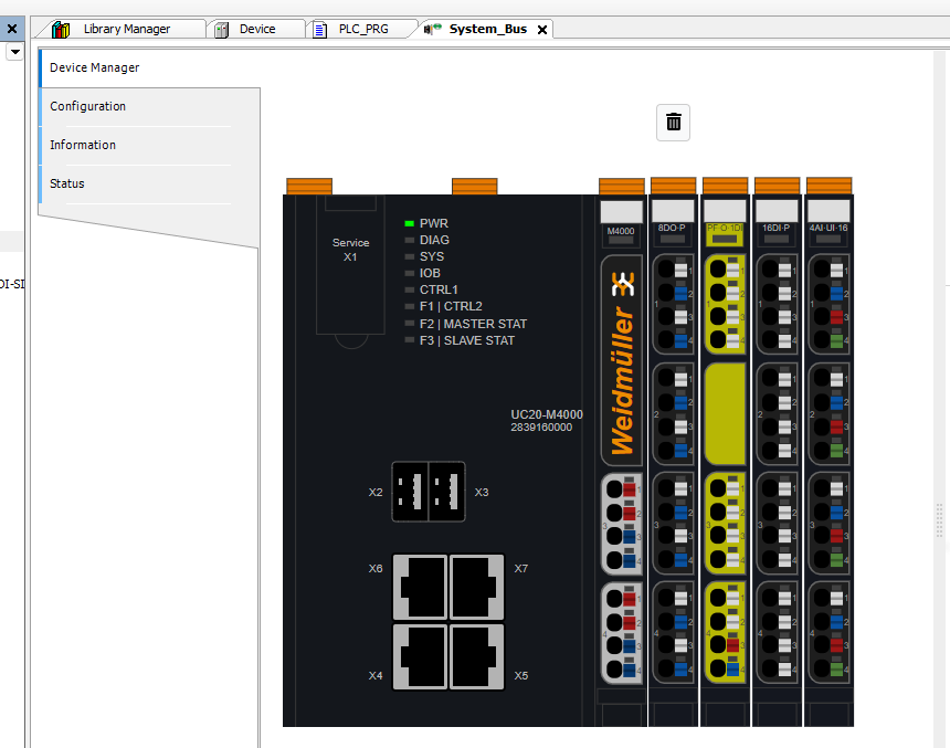
This is the System Bus configuration screen of the M4000.
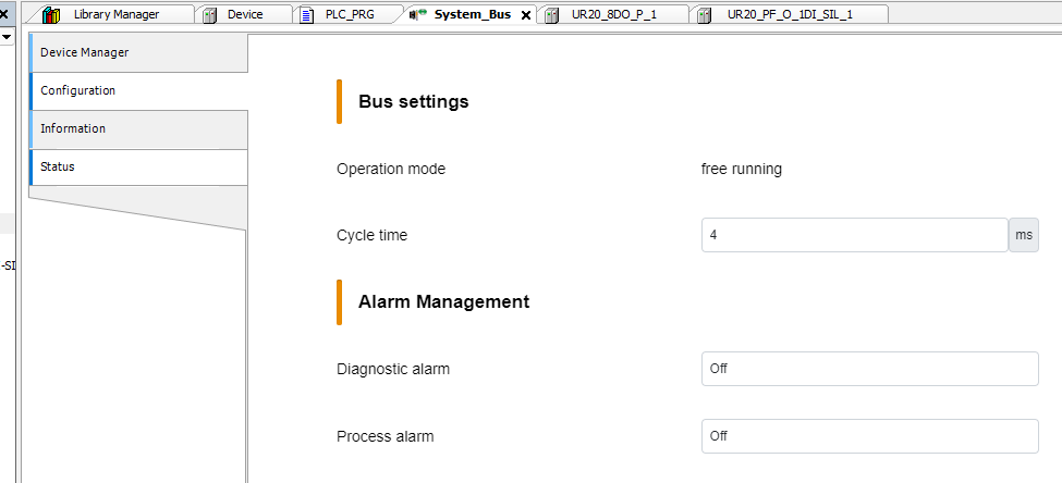
Set the alarm and Bus Cycle Time to match your application.
Device Manager
Next, add modules from the Device Manager section.
Slot1
Slot 1 is installed in UR20-8DO-P, so search for 8DO in Catalogue and Dorp UR20-8DO-P to M4000.
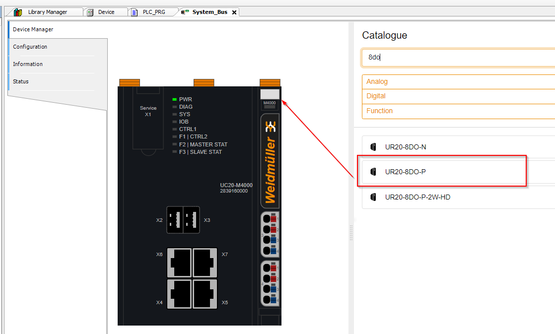
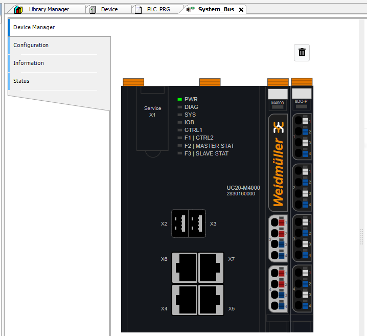
Done!UR20-8DO-P has been added.
Slot2
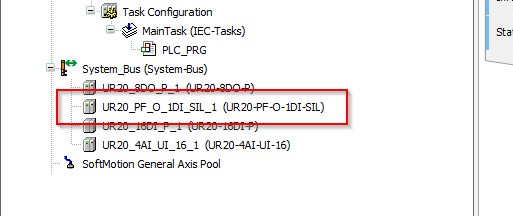
Slot 2 is installed in UR20-PF-O-1DI-SIL, so search for 1DI in Catalogue and Dorp UR20-PF-O-1DI-SIL to M4000.
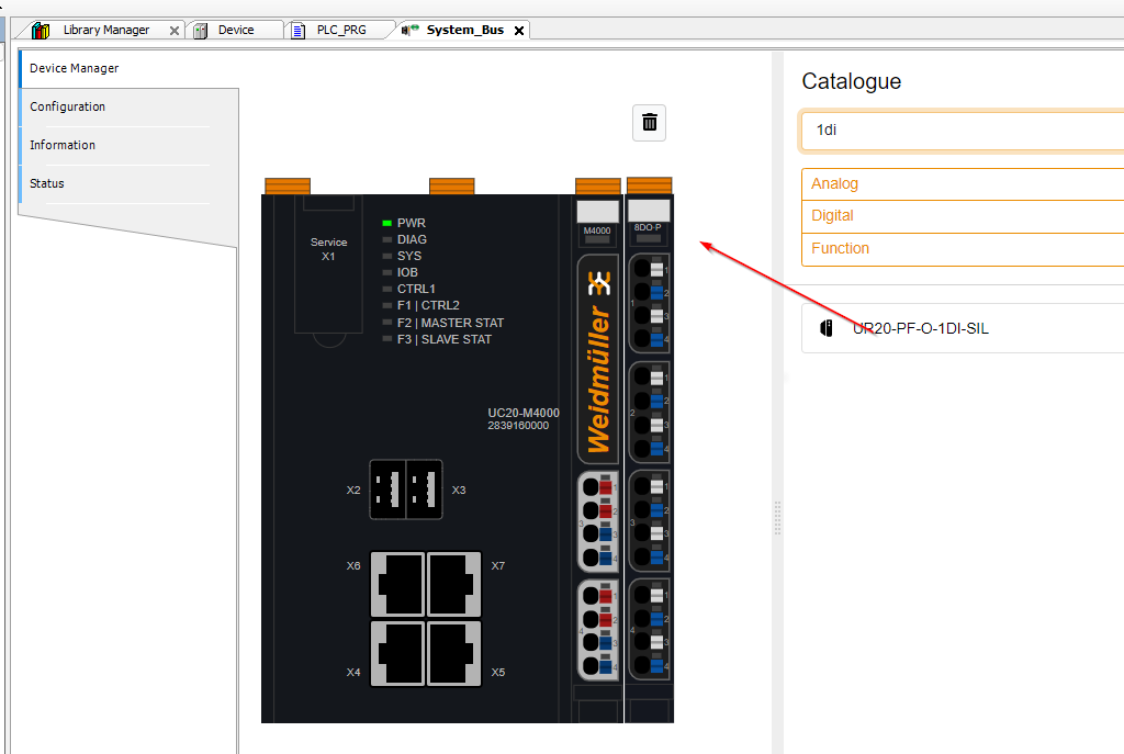
Done!UR20-PF-O-1DI-SIL is added.
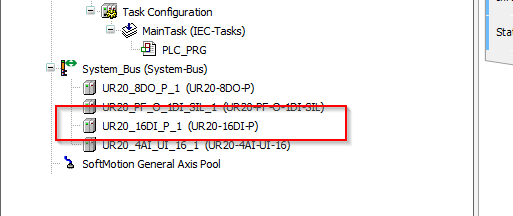
Slot3
Slot 3 is installed in UR20-16DI-P, so search for 16DI in Catalogue and Dorp UR20-16DI-P to M4000.
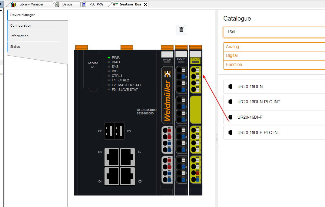
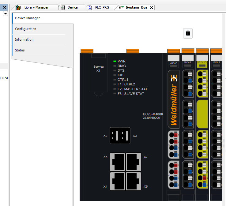
Done!UR20-16DI-P is added.
Slot4
Slot 4 has UR20-4AI-UI-16 installed, so search for 4AI-UI-16 in Catalogue and dorp UR20-4AI-UI-16 to M4000.
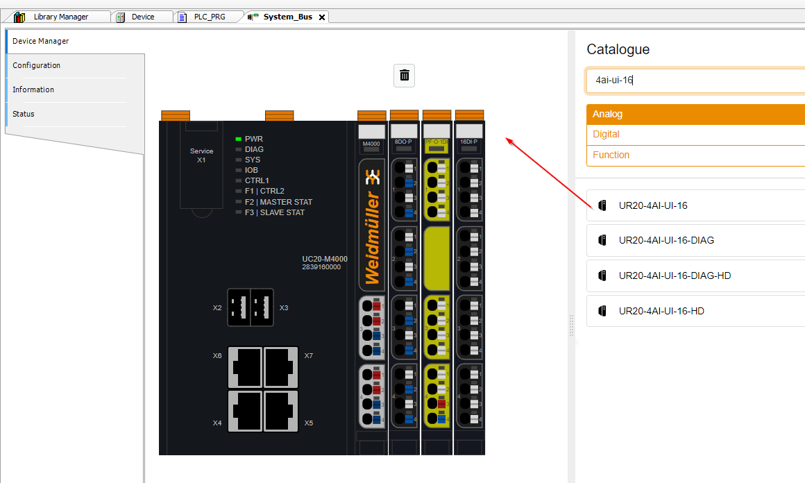
Done!UR20-4AI-UI-16 is added.
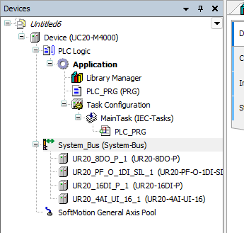
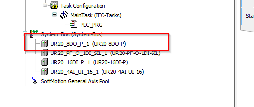
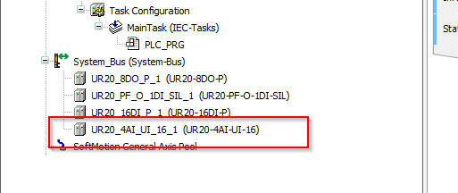
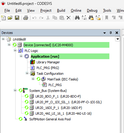
Result
This is the System_Bus set up in this article.
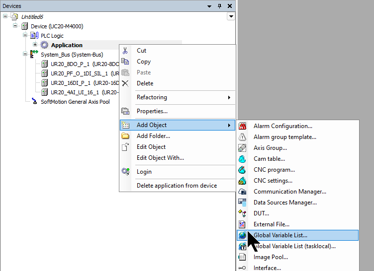
Add GVL
To add a Global Variable List, go to Application>Right click>Add Object>Global Variable List.
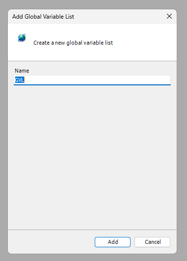
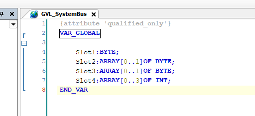
Enter the GVL name.
Define the modules installed in System_Bus and the variables to be Mapped as shown in the diagram below.
Program
FB_UR20_PF_O_1DI_SIL
This is the Function Block that controls the UR20-PF-O-1DI-SIL.
Interface
This is the Interface definition of the Function Block.
| FUNCTION_BLOCK FB_UR20_PF_O_1DI_SIL VAR_INPUT END_VAR VAR_OUTPUT qSafetyInput0 :BOOL; //1=Activate qAutoStartActived :BOOL; //1=Activate qManualStartActived :BOOL; //1=Activate qSafetyInputChannel0:BOOL; //S12,S12 qSafetyInputChannel1:BOOL; //S21,S22 q24VSafetyOutput :BOOL; //24V Safety q24VDCSupply :BOOL; //24V END_VAR VAR_IN_OUT ioByte0,ioByte1:BYTE; END_VAR VAR END_VAR |
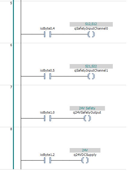
Code
Rung1-4 transfers Bit0-3 of Byte 0 to the output variable.
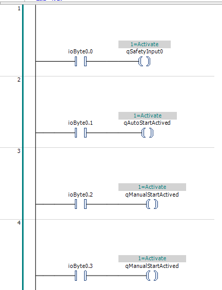
Rung5-8 transfers Bit4-5 of Byte0 and Bit0 and 2 of Byte1 to the output variable.
MAIN
This is the MAIN POU.
Interface
| PROGRAM PLC_PRG VAR SwitchLamp :BOOL; Channel0_Voltage:REAL; Channe11_Current:REAL; Module1 :FB_UR20_PF_O_1DI_SIL; SwitchNO,SwitchNC:BOOL; END_VAR |
Code
This one scaling the analogue inputs with current and voltage values and also calls the Function Block of UR20-PF-O-1DI-SIL, which was created earlier, to obtain the state of UR20-PF-O-1DI-SIL.
| Channel0_Voltage:= (TO_REAL(GVL_SystemBus.Slot4[0])/27648.0)*10; Channe11_Current:= ((TO_REAL(GVL_SystemBus.Slot4[1])/27648.0)*20)+4; Module1( ioByte0:=GVL_SystemBus.Slot2[0] ,ioByte1:=GVL_SystemBus.Slot2[1] ); SwitchNC:=GVL_SystemBus.Slot3[0].0; SwitchNO:=GVL_SystemBus.Slot3[0].2; SwitchLamp:=SwitchNO; GVL_SystemBus.Slot1.0:=SwitchLamp; |
Configuriation
The next step is to set the parameters for each module.
Slot1
Click on UR20-8DO-P in Slot 1.
Module parameters can be set in Module Configuration.
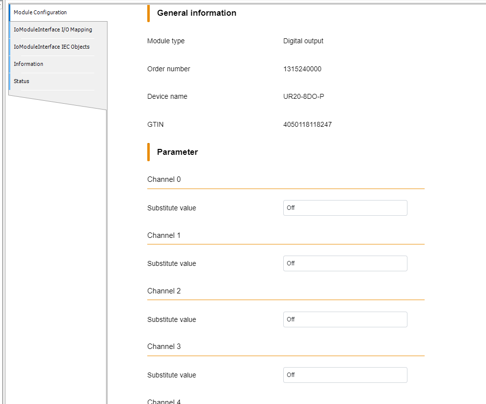
Next, open IoModuleInterface I/O Mapping.
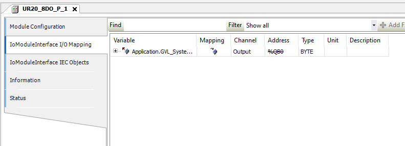
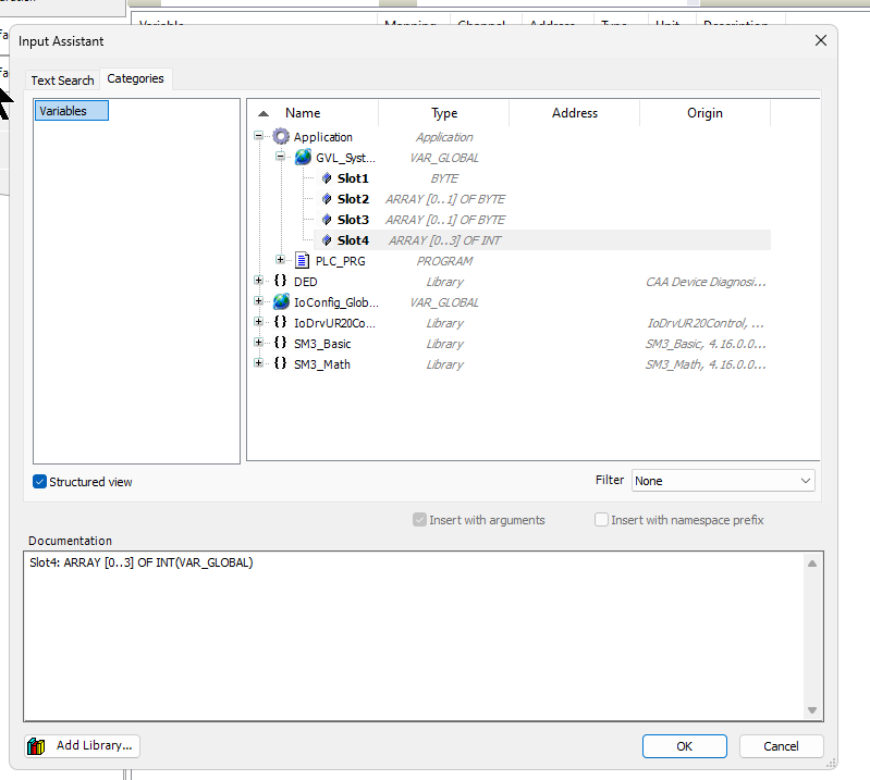
Click on the …button under .
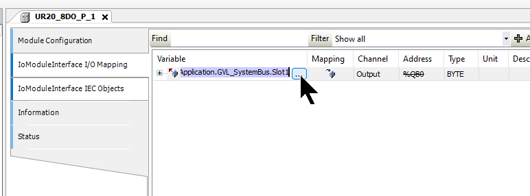
Link to the variables you have just defined in the GVL.
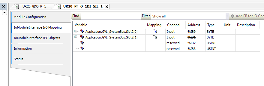
Slot2
Click on UR20-PF-O-1DI-SIL in Slot 2.
Link the input/output data of the UR20-PF-O-1DI-SIL with the programme variables.
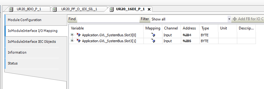
Slot3
Click on UR20-16DI-P in Slot 3.
Link the input/output data of the UR20-16DI-P with the programme variables.
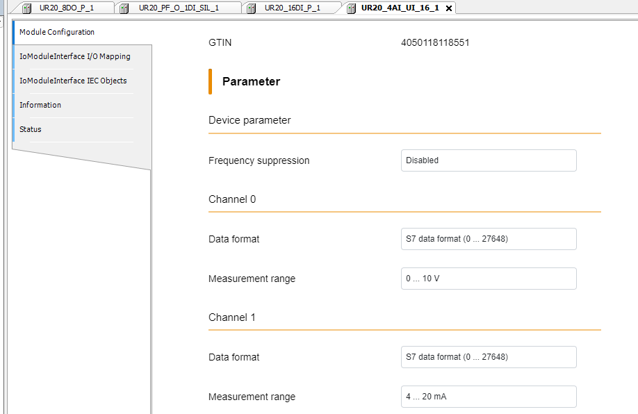
Slot4
Click on UR20-4AI-UI-16 in Slot 4.
You can set the Module parameters in Module Configuration.
Set Channel0 and Channel1 to 0…10 V and 4…20 mA.
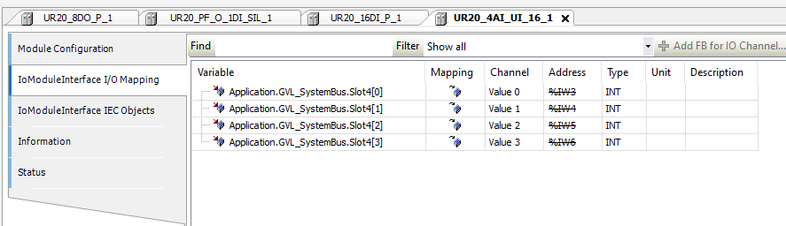
Link the input/output data of the UR20-4AI-UI-16 with the programme variables.
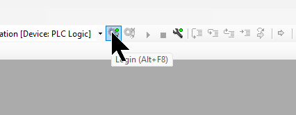
Download
Click on Login and Download your project to the CPU.
Result
You can see how the M4000 works with the DI/AI/DO module in this video.
You can see how the M4000 works with the UR20-PF-O-1DI-SIL module in this video.
Download Project
You can download the article project from this Link.
https://github.com/soup01Threes/Codesys/blob/main/M4000_Tutorial_Part03.projectarchive