This article is related to the new Beckhoff TwinCAT series XTS systems. You often see XTS systems on the Beckhoff exhibition, but they look kind of difficult to play.
I would be happy to experience the XTS system with everyone through this series in a fun way.
Let’s XTS GOGOG!
Install Packages
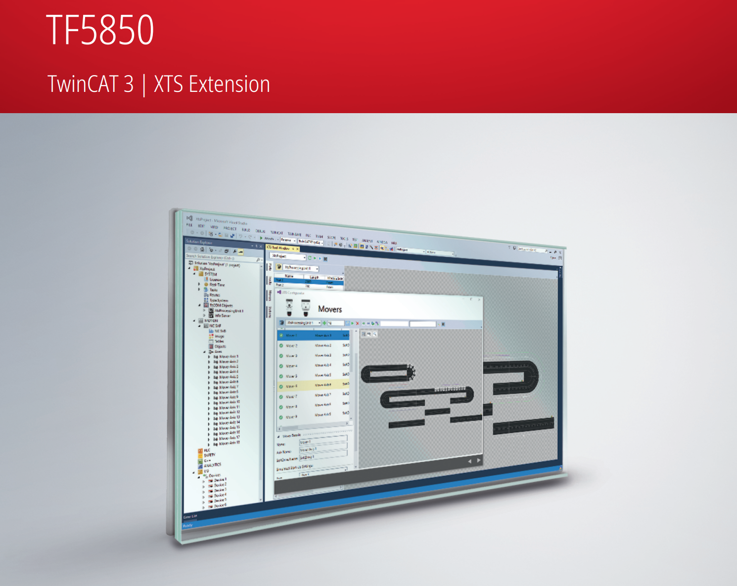
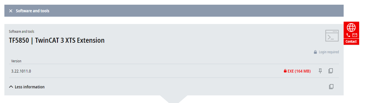
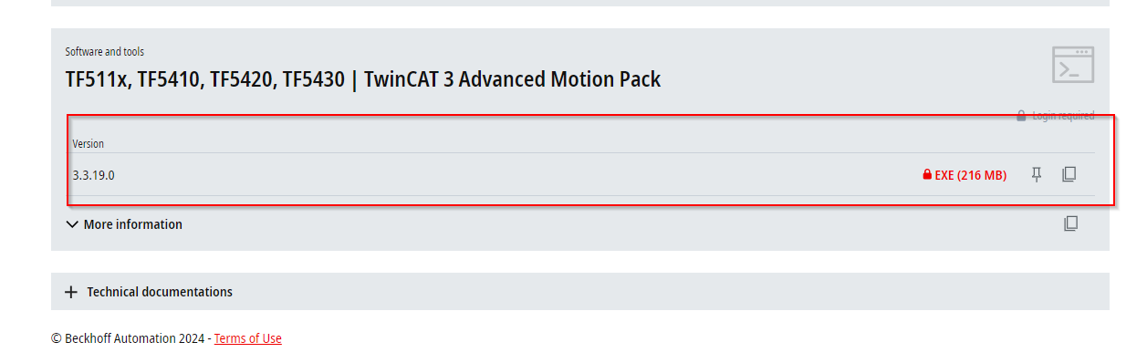
To build an XTS system, the TF5850 and TF5400 packages are required.
Download TF5850 at this Link.
Download the TF5400 at this Link.
XTS Configuration
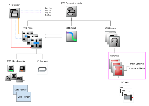
XTS systems are built in configurations where hardware and software components must communicate and function with each other, and the processes and communication paths between software and hardware must be understood in order for the system to work as desired.
The components of this XTS system include;
- modules
- guide rails
- movers
- Several software components running on the IPC
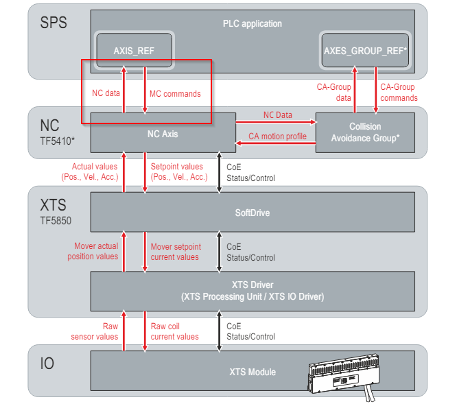
XTS communication is based on the CANopen communication structure, which transfers additional data and calculates coil currents, commutation, dynamics and motion profiles.
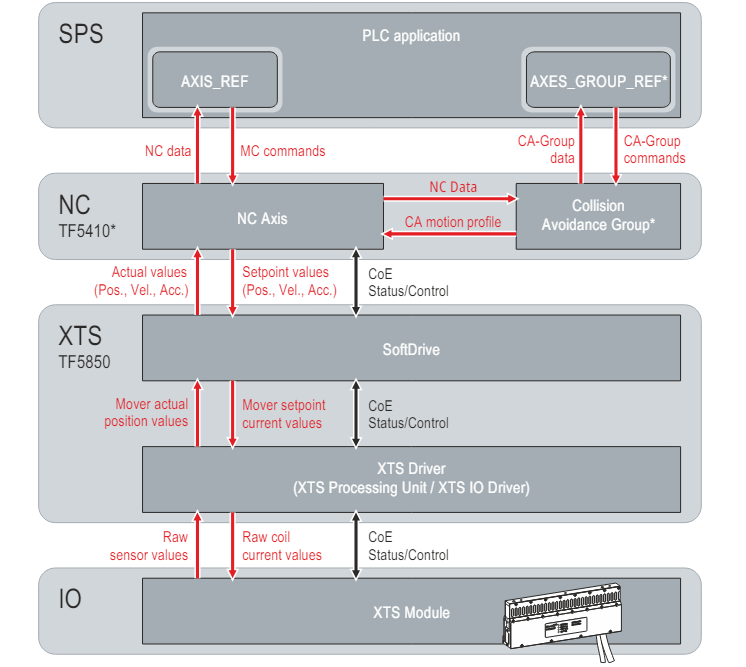
XTS Modules<–>XTS Driver
The basis for communication is the hardware comprising the XTS Module, which sends sensor values to the XTS Driver.
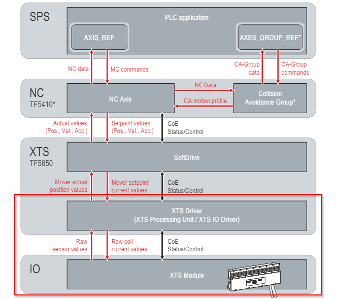
XTS Driver<–>SoftDrive
The XTS Driver uses the sensor values of the XTS Module to determine the position of the Mover and sends the position values of each Mover to the respective SoftwareDrive.
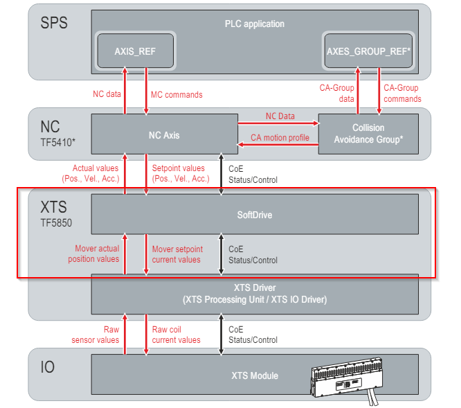
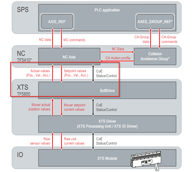
NC Axis<–>SoftDrive
The SoftDrive sends the current Mover position and speed values to NC Axis.
NC Axis generates Motion Profiles based on the received values and sends the position and speed set values to the SoftDrive.
SoftDrive interpolates the values, compares the set value with the actual value and sends the current value of the Mover obtained from the control structure back to the XTS Driver. Finally, the XTS Driver calculates the current set value and sends it to the coil of the XTS Module.
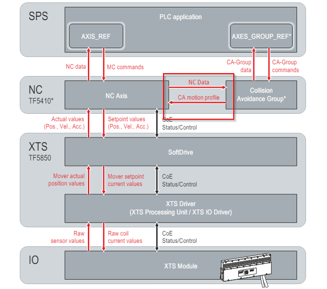
NC Axis<–>Collision Avoidance Group
If the NC Axis is included in a Collision Avoidance Group (Collision Avoidance), the NC Axis receives an external set value representing the operating profile of each Mover.
NC Axis<–>AXIS_REF
Motion and management commands are transferred by the user directly from the library of the PLC application to the NC Axis or Collision Avoidance group (Collision Avoidance).
Basic principles
XTS Software’s Operating Interface simplifies the working and handling of large, sophisticated systems implemented with XTS and enables rapid commissioning and intuitive operation thanks to its simple screen configuration.
This makes it very easy to set up a large number of XTS systems, regardless of their length, geometry and variants.
In its XTS Software, the main purpose of the XTS Software is to support various software functions such as Track Management and Leave and Arrive functions,
- Utilizing the Track Management function, the XTS system can be divided into individual sections, which can then be combined to form a continuous Track. This allows the individual sections to be mechanically aligned in different ways and can be used more flexibly on the system.
- The Leave and Arrive function allows Movers to be removed or added while the system is running.
The following is an example of an XTS Main configuration.
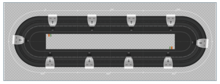
Closed XTS system
For example, the 3 m XTS Starter Kit configuration is a Closed XTS System with 180° rotation and 10 Movers.
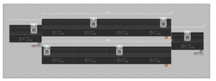
XTS system with Track Management
The XTSTrack Management System is a switch or elevator-like XTSTrack Management System with four XTSParts and six Movers, as shown in the diagram below.
The difference between these two systems?
The main difference between the two system configurations is that in the Closed XTS System, the order of Modules and Movers is always constant. So there is only one XTS Track that Movers can move to.
In an XTS System with Track Management functionality, Modules can change their position and align with other Modules. So you can change the order of Modules and Movers to form new Tracks. To get an overview of these new features, introduce the XTS Parts and XTS Tracks functions.
More about Track Management…
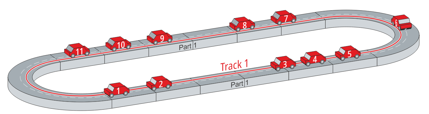
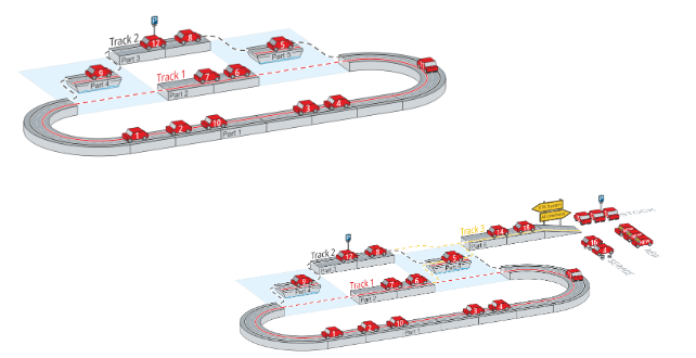
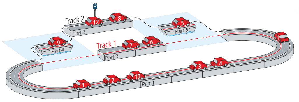
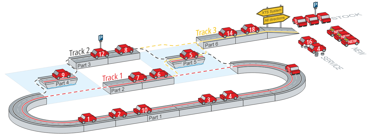
For example, suppose that there is now a Track System as shown in the diagram below.
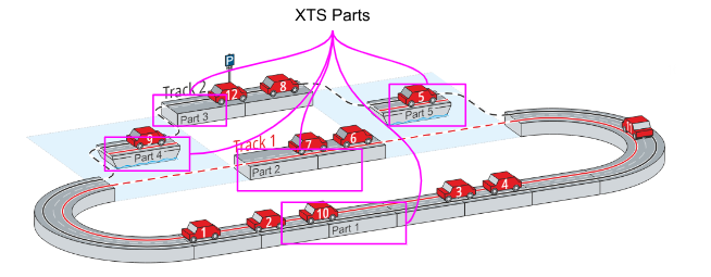
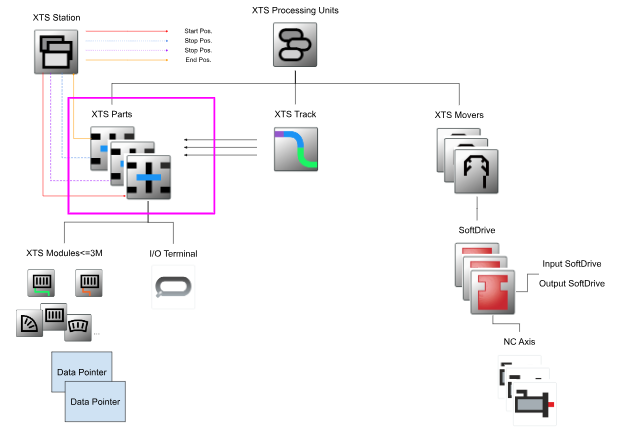
XTS Parts
XTS Parts are the physical hardware components on which mobile vehicles run, the equivalent of road parts for cars.
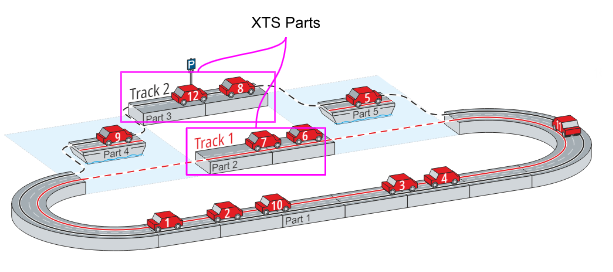
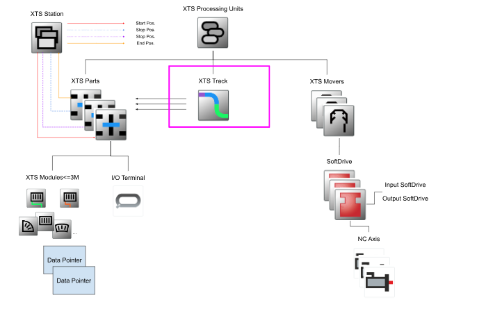
XTS Track
XTS Track is the actual track of Movers, where individual hardware components are assembled.By assembling the individual hardware components, vehicles create a track that may have different surface sections.
How to Config?
TwinCAT projects can be created using the XTS Configurator to create a simple XTS system, with one XTS Parts and one XTS Track Track for all Movers.
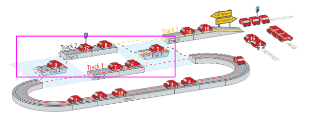
More sophisticated XTS systems
More complex XTS systems can combine several XTS Parts to form different XTS Tracks.
Leave and Arrive function
As shown in the diagram below, a car ferry can be used between two possible tracks, allowing vehicles to be moved on different routes; the Leave and Arrive function allows one Movers to be taken out of the system and additional Movers to be put into the system.
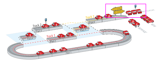
Entrance and Exit
Outside XTS Parts will be a parking area for unused cars, a new car dealership and a repair shop for broken-down cars, with the road section acting as an entrance and exit.
When a vehicle is transferred to the XTS system, it can do this.
- Movers can be removed for maintenance
- Add new Movers as required
- Remove Movers that are no longer required
Configuration Setup
XTS hardware and I/O components, for example, can be created manually or quickly and easily using TwinCAT’s XTS Configurator and XTS Simulation Builder. Before you do this, you should understand the configurations in the XTS system.
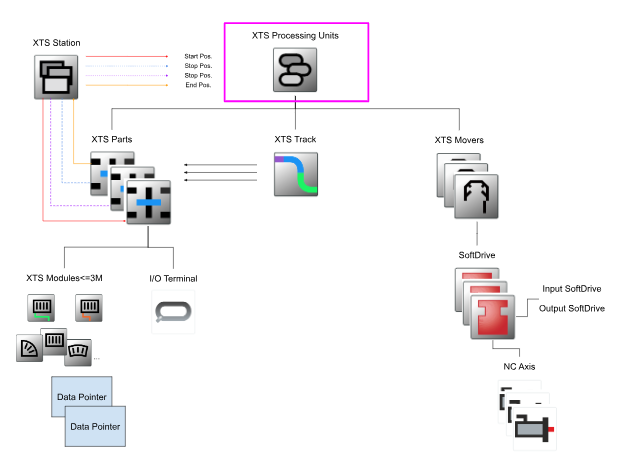
The main components of the XTS system configuration are as follows.
- XTS Processing Units
- XTS Parts
- XTS Modules
- XTS Tracks
- XTS Movers
- XTS Stations
- NC axis
- SoftDrive
- I/O Terminal
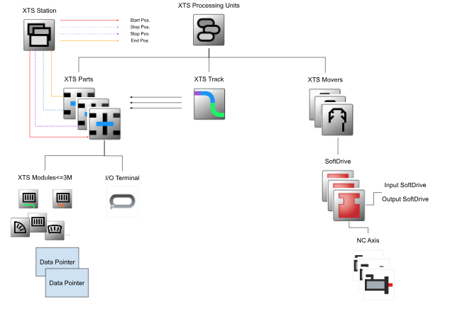
Processing Unit
The Processing Unit is the heart of the XTS system, all the necessary objects are concentrated in the Processing or Unit and logically linked to each other (replacing the XTS IO Driver object of the previous version).
Depending on the number of individual systems used in the application, one or more Processing Units can be created. Note that each Processing Unit must have at least one task that is not used by another Processing Unit.
Parts
Parts are the minimum components required for an XTS system, or at least one module one in a system. Typically, a Part consists of one Infeed Line, and multiple supplies can be made within a Parts.
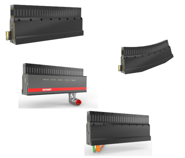
Module
The Module corresponds to the physical module AT2xxx-0xxx and is always in the Lower Layer of the component. Note that Tasks must be assigned to each Module. In addition, Infeed Modules and Only modules with Connector have an EtherCAT communication interface.
In addition, Modules have Simulation Mode and Machine Mode.
- Simulation Mode
No hardware required mode. - Machine Mode
A physical AT2xxx-0xxx module must be assigned to each module.
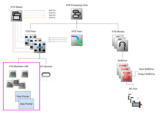
The physical AT2xxx-0xxx required for Machine Mode can be found on the Beckhoff website.
Track
A Track is a pathway that Movers can use and consists of one or more Parts. Parts can also be multiple in a particular XTS Track or inserted into several different Tracks, allowing you to create as many Tracks as you like.
To create a Track, it is necessary to define which Parts are included in this Track and in what order the Parts appear.
It is important to set whether Track is closed or not. This setting determines whether Movers run in an endless circle or whether the system has an end point.
If that designation is incorrect, Movers may leave the system and, in the case of Closed System, Movers cannot move in a circle as they normally would.
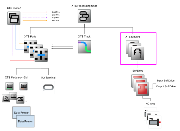
Movers
Movers are a key component of the XTS system together with Modules, which move over the Parts in the system by activating the corresponding Track using the NC function of TwinCAT 3. In addition, 250 Movers with the Collision avoidance function can currently be controlled simultaneously within a project.
Each Movers is connected to the NC axis via a SoftDrive and has its own SoftDrive Object which communicates with the NC and is compatible with the basic control commands.
SoftDrive is the Software Controller for the axis controlling the Movers, SoftDrive can adapt the Movers’ control to different loads.
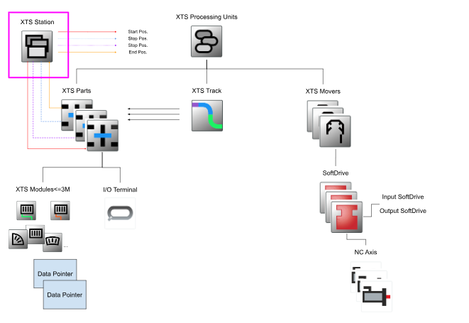
Stations
The XTS Station functionality is currently still in the beta phase and in the future more features ,and information may become available and the current interface may change.
Station is very useful for managing the system and associated applications, providing information on where individual processes take place within the system and showing the overall structure of the application. This information can also be read out using the XTS Utility library in the PLC.
Each Station has its own identification data.
- ID
- Colour
- Name
- Description
In addition, regardless of the Is Enabled selection box, each Station has a defined start and end position; within a Station, you can set where Movers should stop, where they should stop to indicate where a particular task has been completed, and so on.
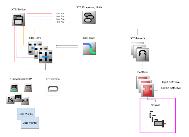
NC Axis
Each Movers is connected to an NC Axis that generates a set value profile for the movement of the respective Movers; the NC Axis is created in the MOTION item in the project and linked to the Movers via the SoftDriver Object.
NC Axies can be operated directly via the TwinCAT NC interface or via a PLC using a library with PLC-open compliant Function Block.
SoftDrive
The SoftDrive connects each Movers to the NC axis and uses the NC setpoint profile to control the position, speed and current to move the Movers and generate the required current and current direction. The connection between the SoftDrive and each Movers is also made via a DataPointer.
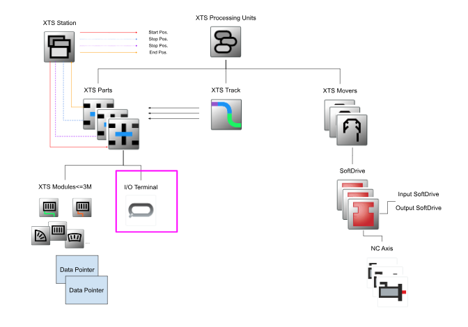
I/O terminal
Each Module is connected to the IPC via EtherCAT and this connection is called an I/O terminal.Each I/O terminal is assigned an infeed-line physical module and is supervised by an EtherCAT master.
After an EtherCAT network scan, the connection status, individual sensor data and hardware status data can be called up in the I/O overview.
The Driver connection of the I/O terminal and Module is then made via DataPointer.
Implementation
Create New Project
Install the TF5850 and TF5400 packages and start TwinCAT XAE; Ok from TcXaeShell or from VS 2019.
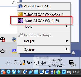
VS2019 will be used in this article.
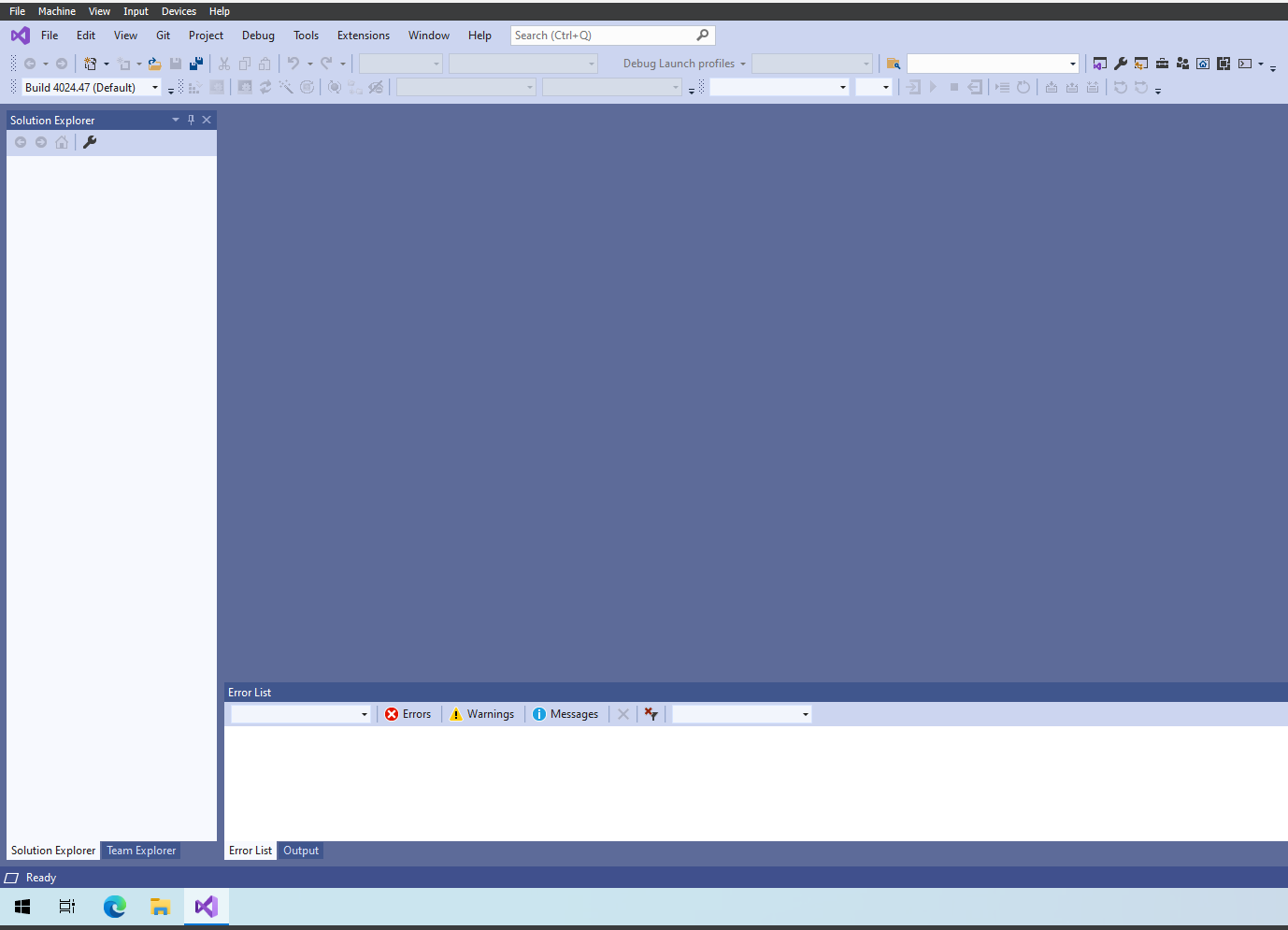
XTS Tool Window
Go to Extension>TwinCAT>XTS>XTS Tool Window.
The XTS Tool Window is the user interface for all XTS-related components of a TwinCAT project.
- XTS Configurator
- XTS Simulation Builder
- XTS System View
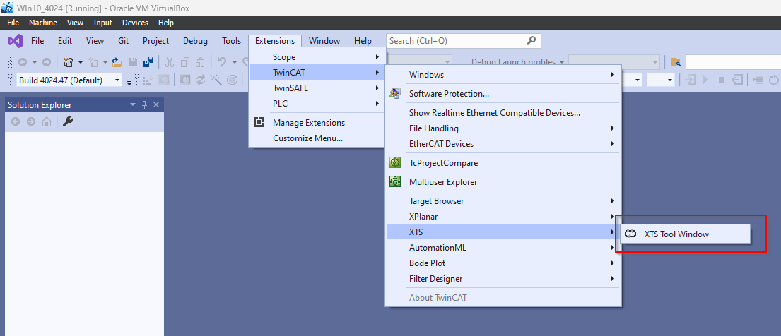
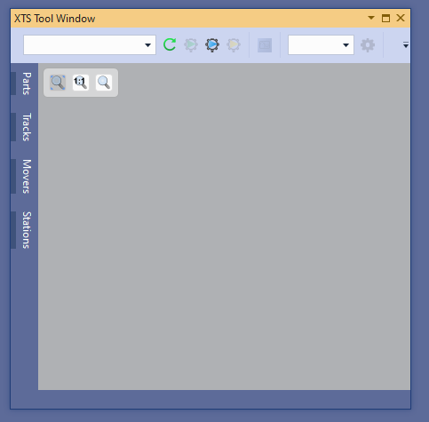
The XTS Tool Window is now displayed.
XTS Simulation Builder
Of course I do not have an expensive device like the XTS, so I will develop the article on Simulation.
The XTS Simulation Builder allows you to create virtual structures of XTS hardware and generate I/O components for simulation in TwinCAT.
This handy XTS Simulation Builder is intuitive and allows you to easily build an XTS system in Simulation. In addition, many configuration options of the XTS software are supported, allowing you to make full use of the tool for planning and simulating new XTS systems.
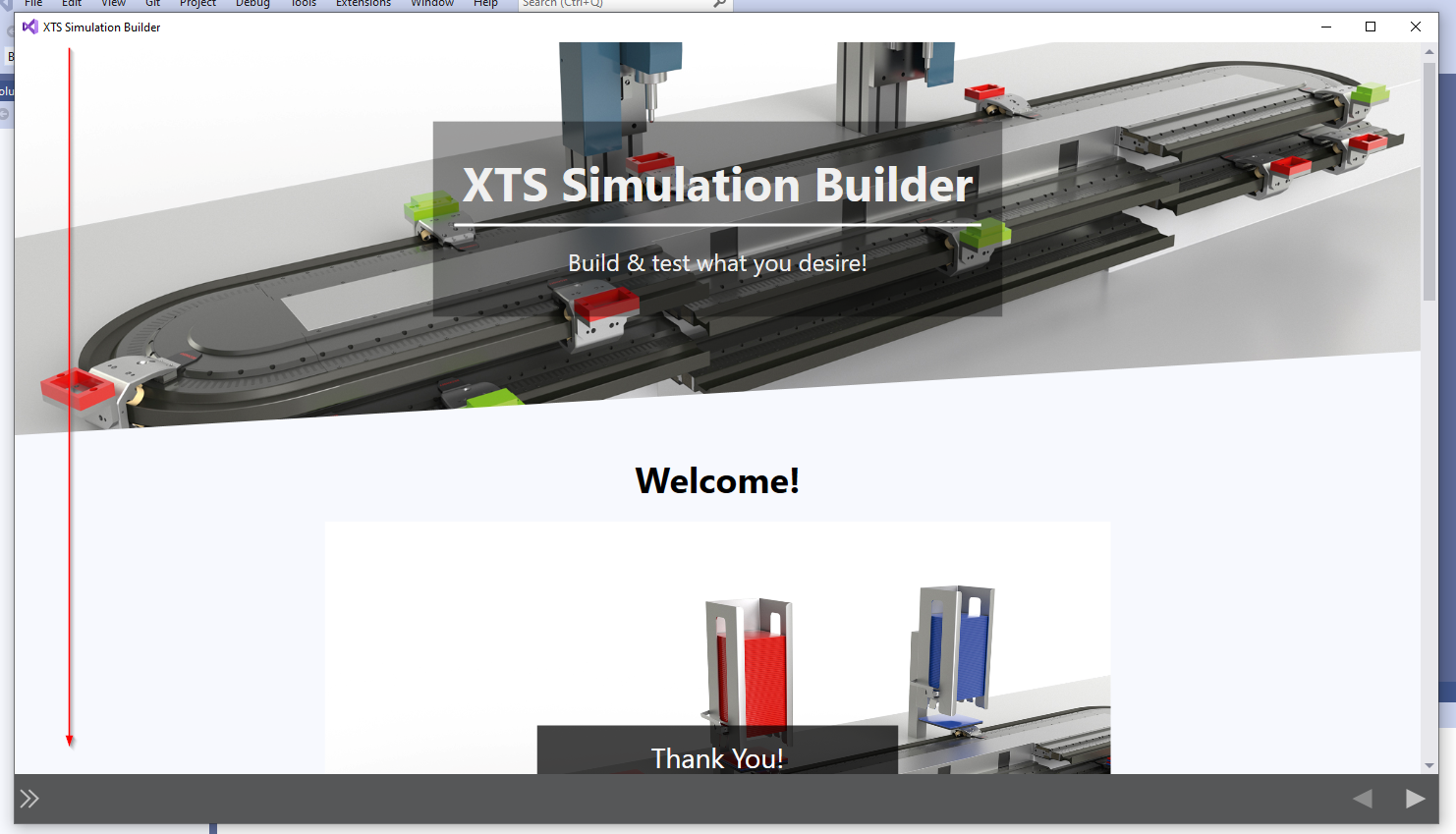
To start the XTS Simulation Builder, click on the button in the red box below.
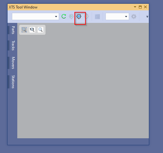
Done!The XTS Simulator Builder has been launched.
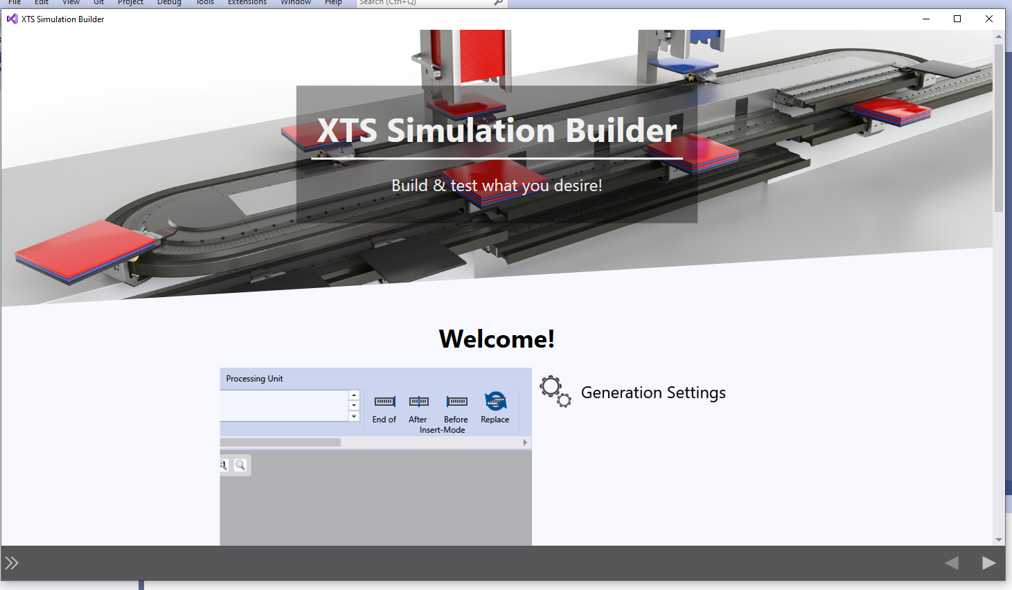
Scroll to the bottom of the XTS Simulator.
Using Template
The XTS Simulator Builder provides several Templates, so the Oral Template will be used in this article.
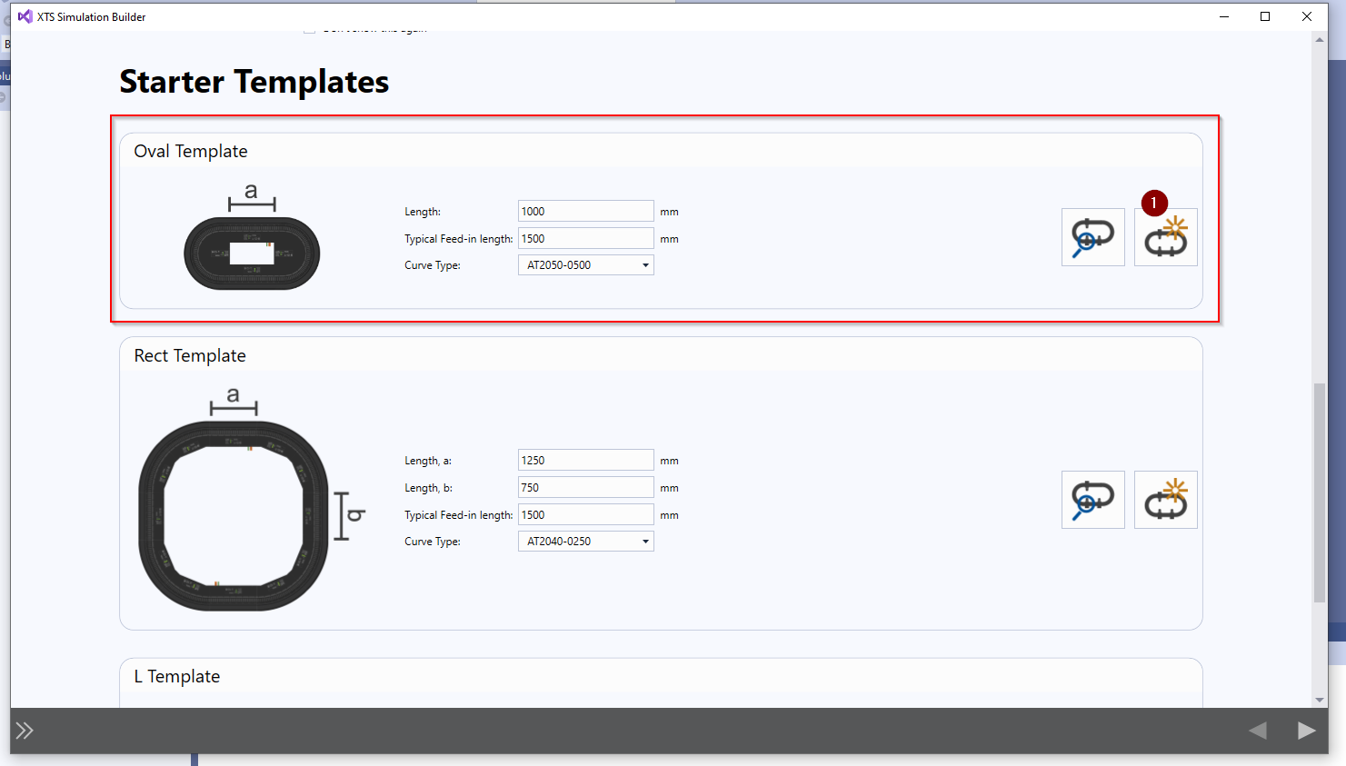
Done!A Closed XTS System was created simply by One Click.
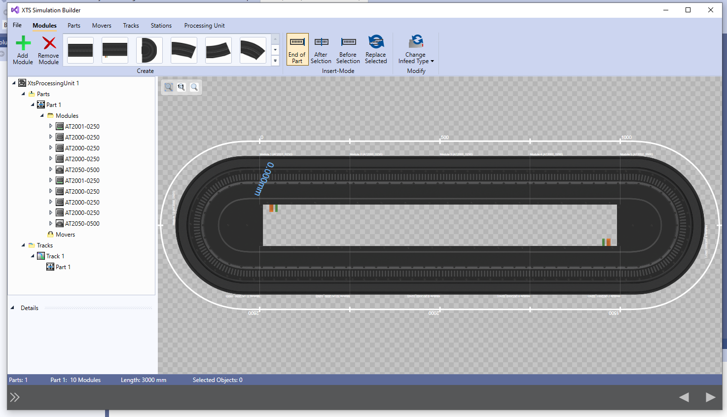
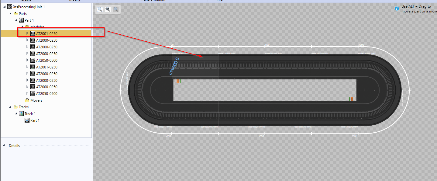
Where are the Modules?
Since we are here, let’s review the XTS System components once again: As we mentioned that Modules correspond to the physical module AT2xxx-0xxx and are always in the Lower Layer of the component. So, as you can see in the figure below, the Module Folder contains a lot of Modules, such as AT2001-250.
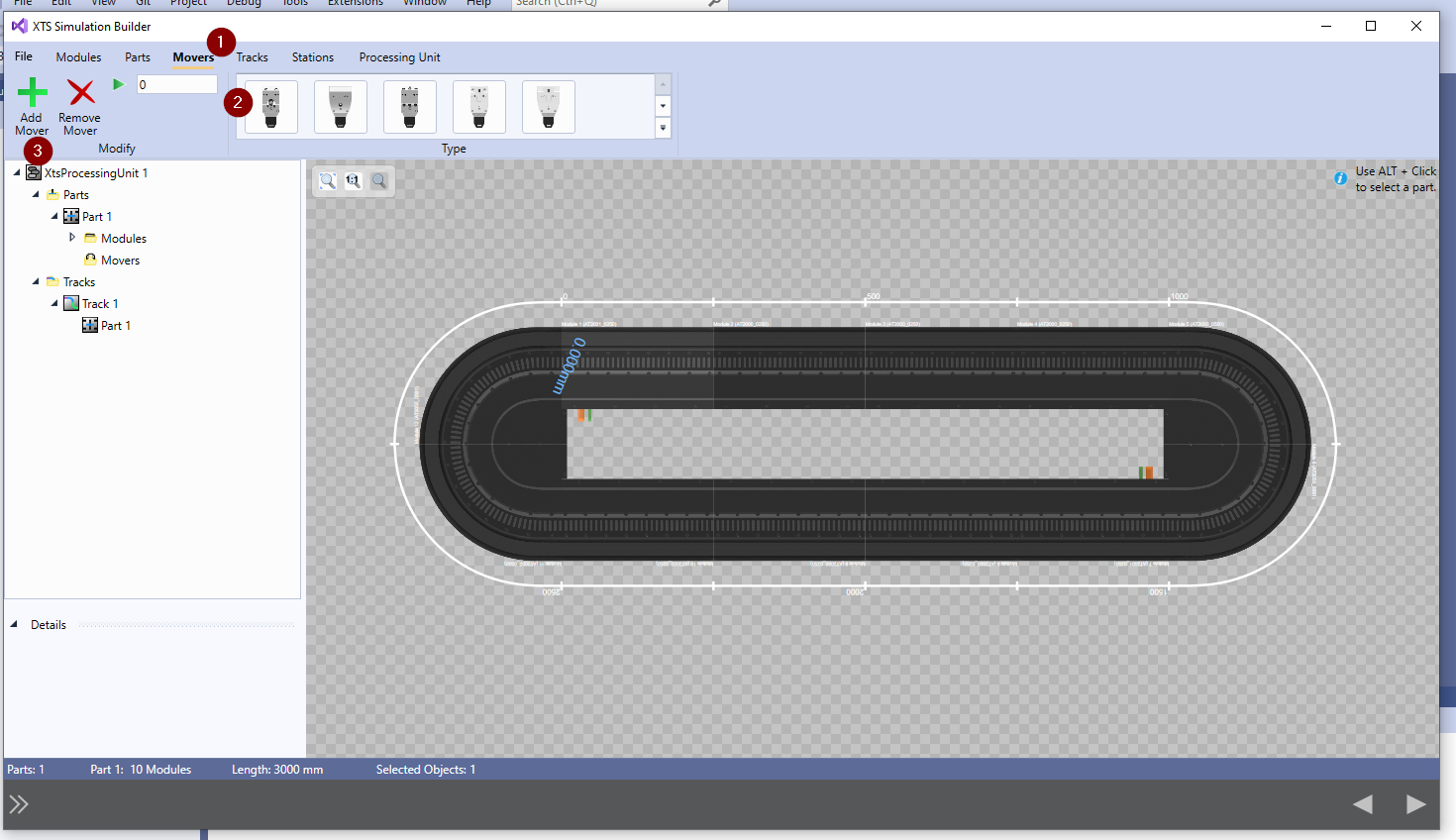
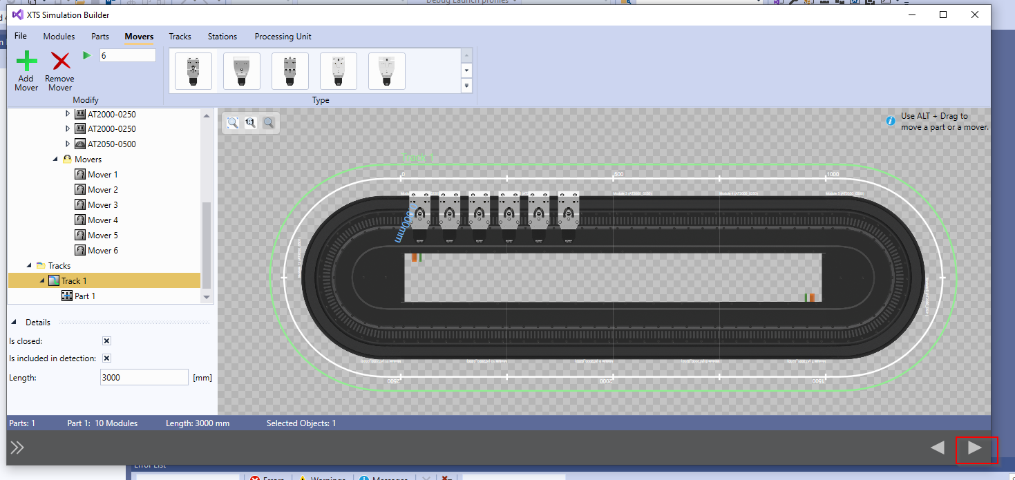
Add Movers
Next, to add Movers, select the Movers you want to add from the Movers Tab and press >+Add Mover.
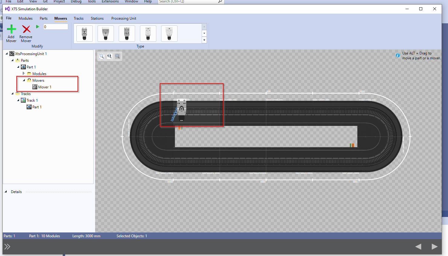
Done!Mover has been added.
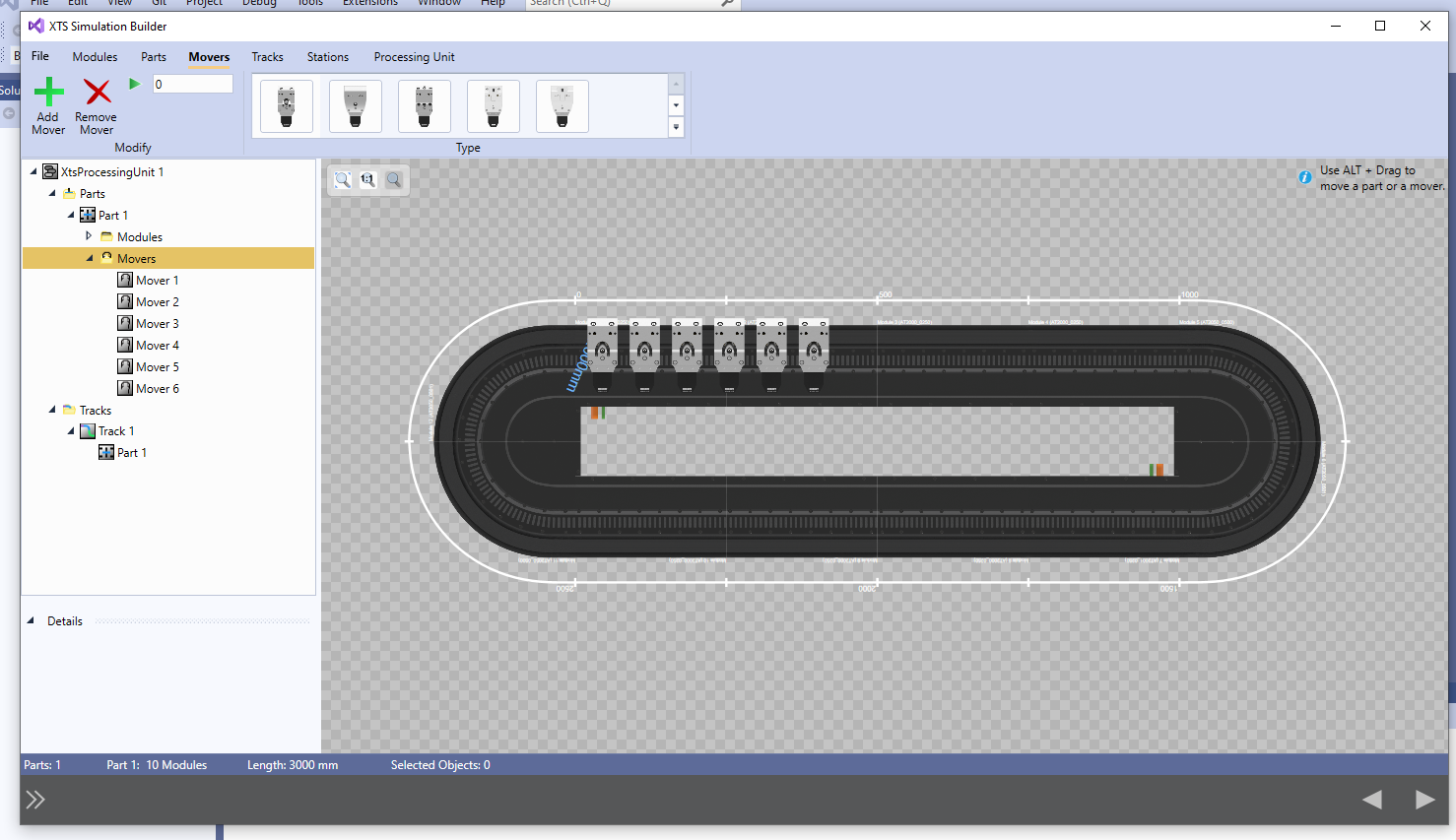
A total of six Movers were added using the same operation as before.
Where are Tracks?
You may have noticed that there is a Track Folder.
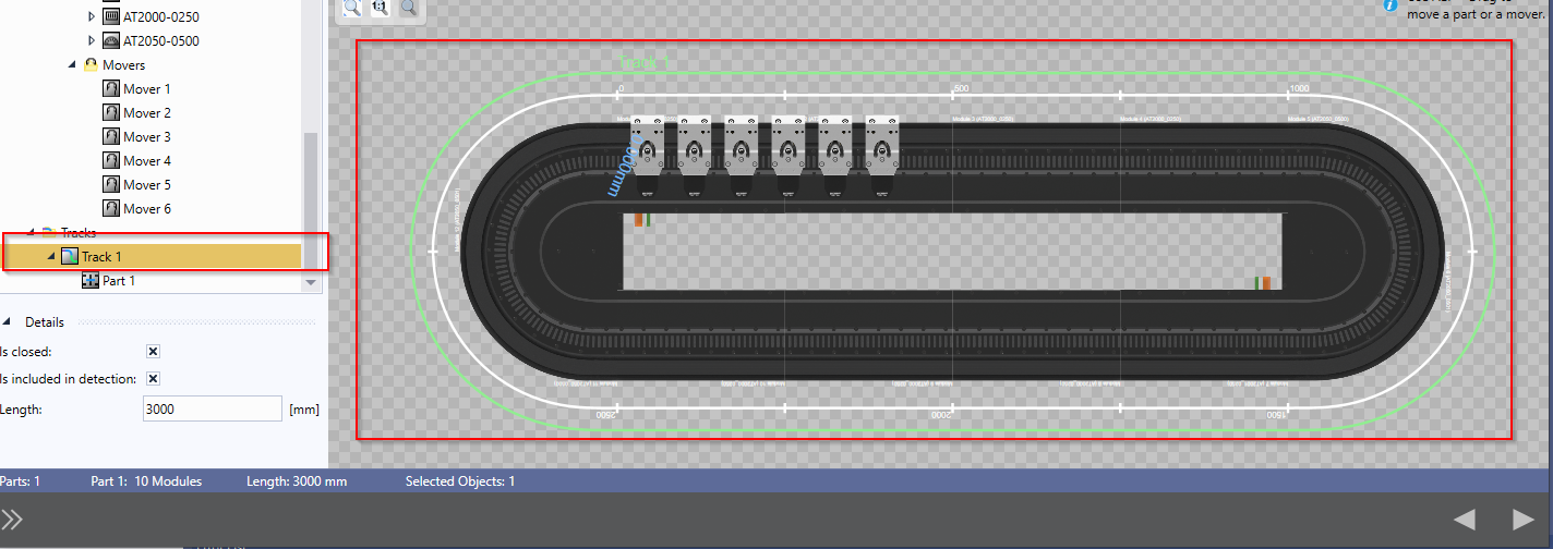
As explained earlier, a Track is a route that Movers can use, consisting of one or more Parts.
The XTS System in the diagram below is only Track 1, which is the entire Closed XTS System.If all settings are OK, proceed to the next step using the right arrow in the red frame.
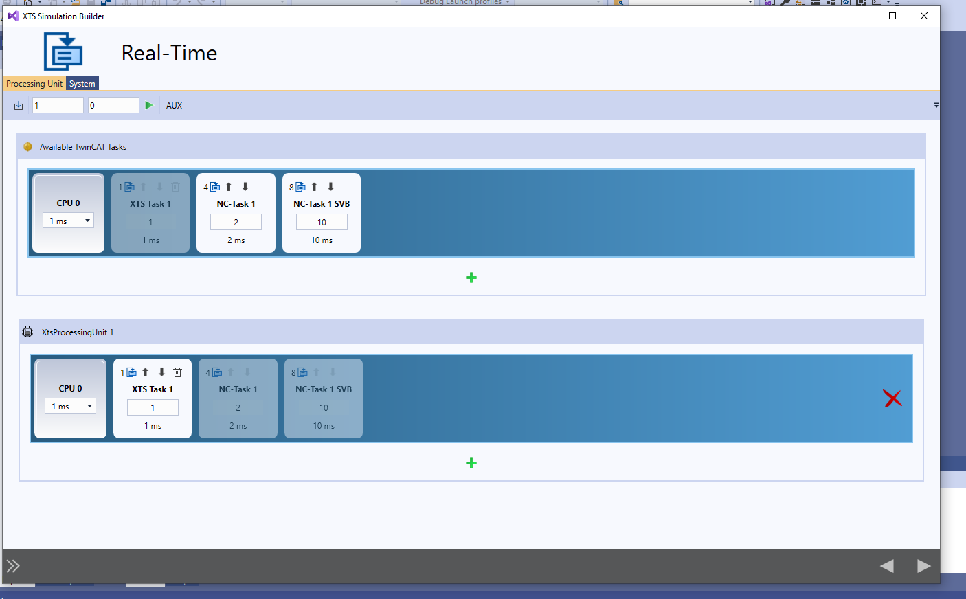
Configure Real-Time
In the next Real Time screen, you can set the Task and XTS Process Unit assignments. This time, since it is only Simulation, I think it is OK to proceed as it is.
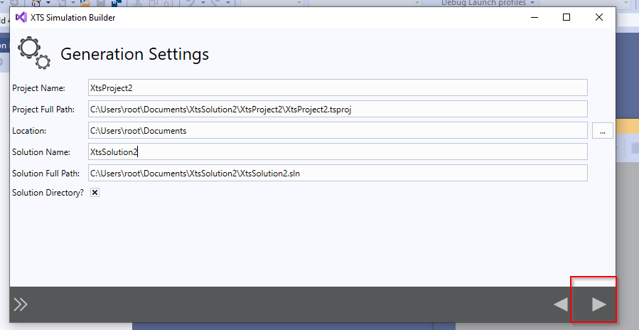
Generate Project
Hardware Configurations created in the XTS Simulator Builder can be imported directly into the project by clicking on the right arrow in the red frame.
Done!Finally, click the right arrow in the red frame one more time to exit XTS Simulator Builder.
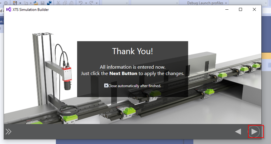
Please wait a moment.
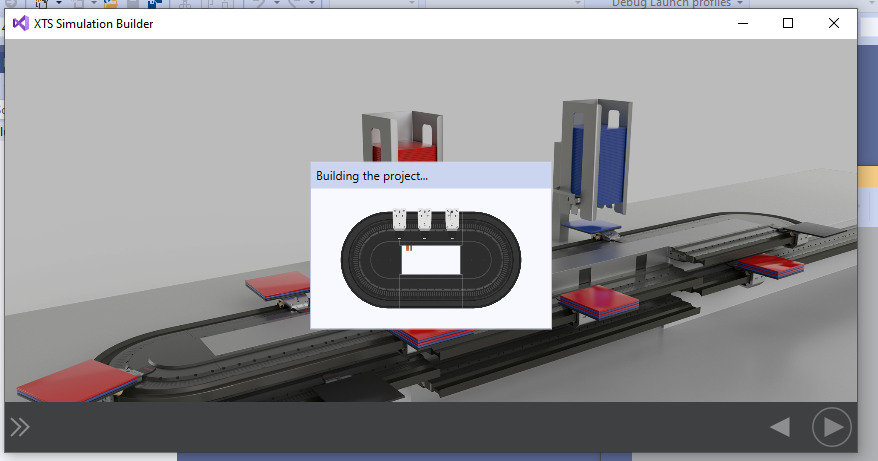
Result
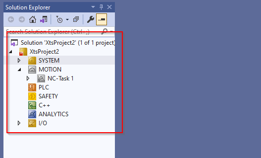
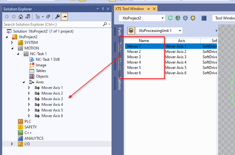
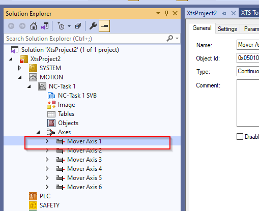
Done!The XTS Simulator Builder project you have just built has been added to the TwinCAT project.
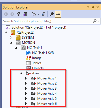
The Axes item also contains six Movers.
Let’s check one more time from the XTS Tool Windows mentioned earlier.
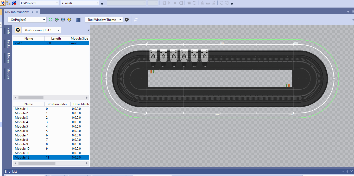
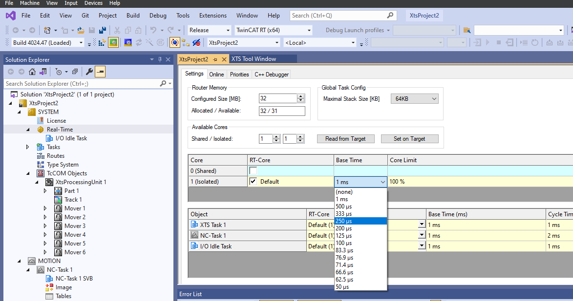
Base time
Next, set the Real Time>Base Time item to 250us.
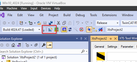
Activate Configuration
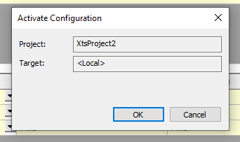
Finally, click Activate Configuration to Download Hardware Configuration.
OK to proceed.
OK to switch TwinCAT Runtime to Run Mode.
Result
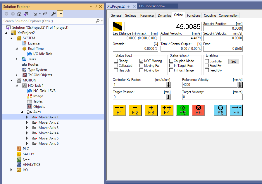
Let’s Power-ON Mover Axis 1 first.
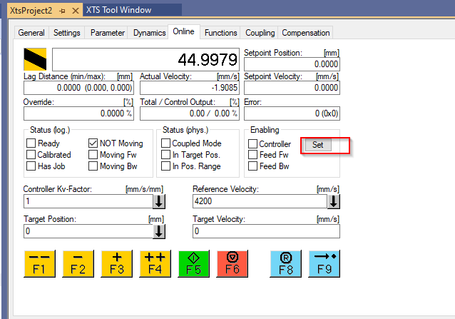
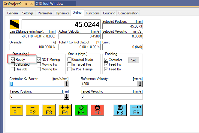
In the Online screen, open the Control Panel for Mover Axis 1. As mentioned earlier, the Movers will eventually be tied to the NC Axis of the TwinCAT project, so whether it is XTS, XPlanar or regular Servo, the control panel is the same.
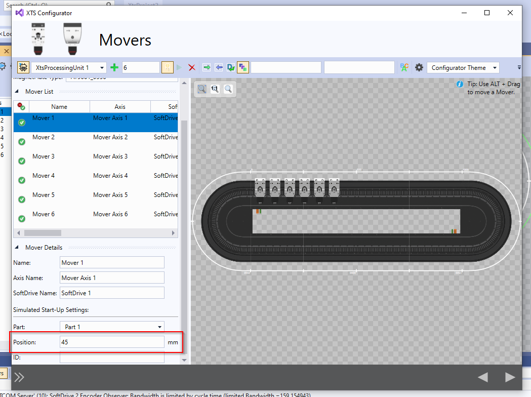
The current position of Mover Axis 1 is now at 45 mm, which is the Start Position of Mover Axis 1.
Actually, in the XTS Configurator mentioned earlier, each Mover has an item called Simulation Start-up Settings, where you can set the start-up position at the Position.
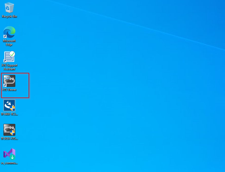
When you install the TF5850, the Desktop also installs a tool called XTS Viewer. Using that tool, you can see the XTS system in action in 3D.
This is the XTS Viewer screen.
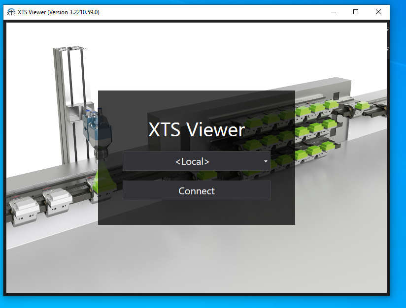
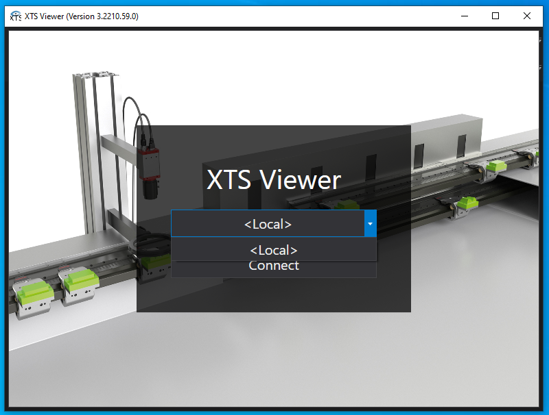
Default is set as <Local>, but it is also possible to connect to other TwinCAT Runtimes from the Drop List.
In this article, we will connect to the Local TwinCAT and proceed with Connect.
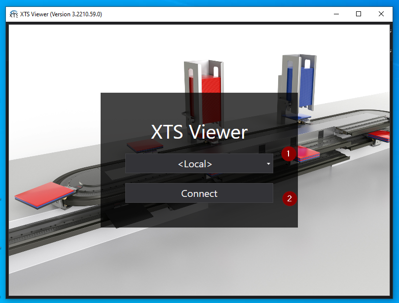
Done!XTS Viewer and Local TwinCAT Runtime are now connected.
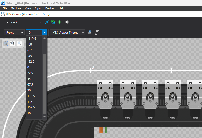
If you want to change the angle of the entire XTS System, you can set the angle you want to display from the Drop-List.
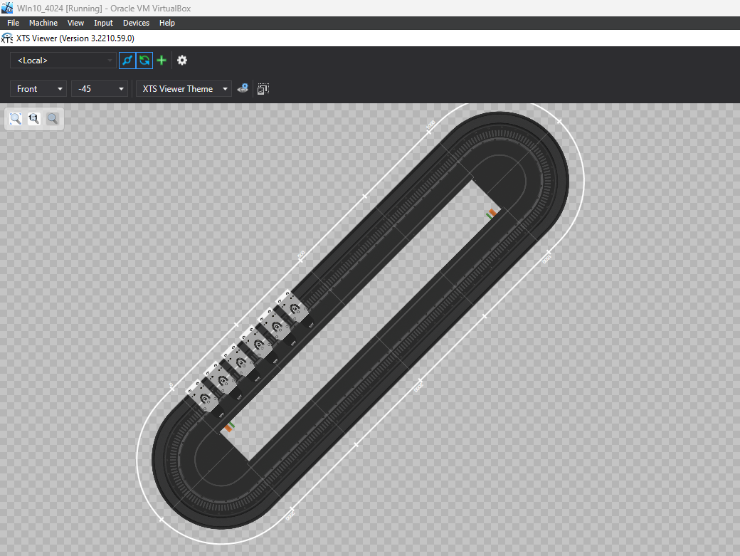
Done!The current XTS System is -45 degrees.
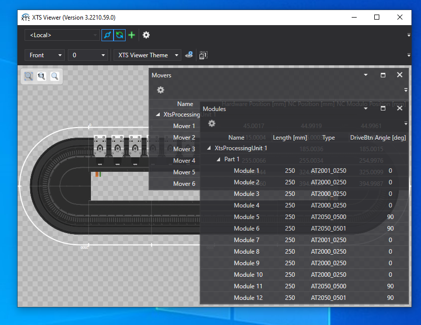
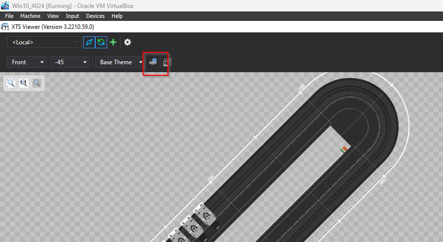
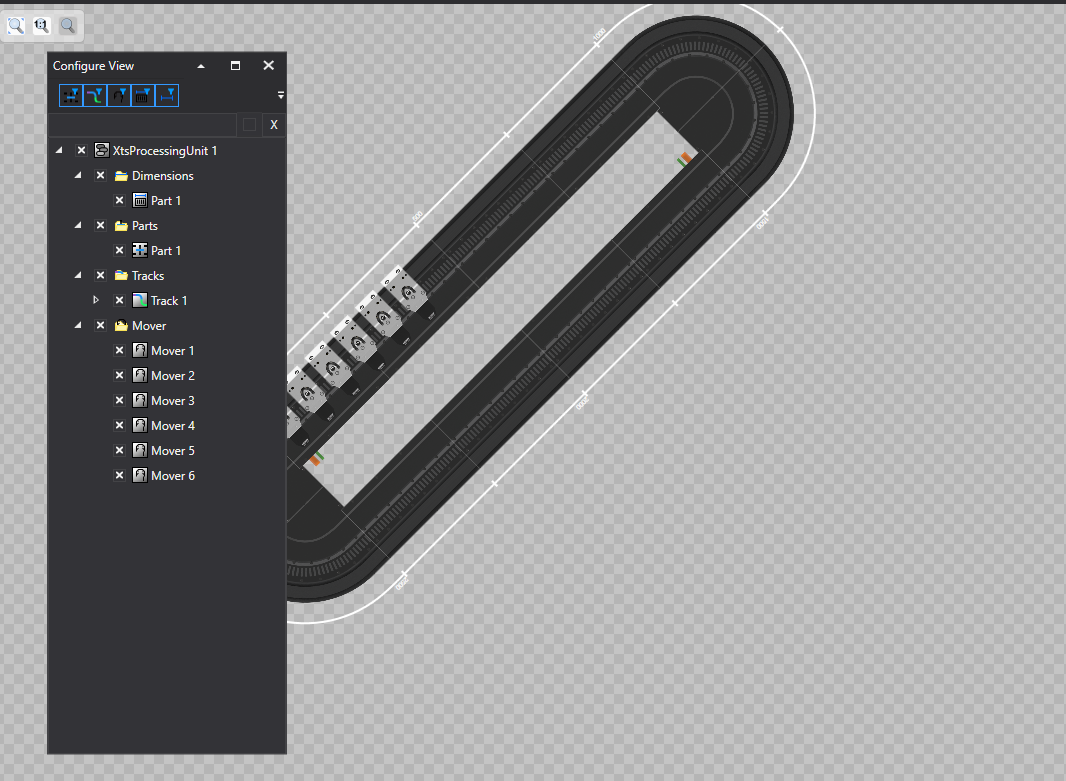
Next, click on the button in the red frame to list the components in the relevant system.
Done!
Now click on the Set button under Enabling to switch the Mover Axis 1 power on.
The Set Enabling screen appears.
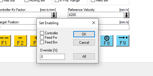
Put in the Checkboxes for Controller, Feed Fw and Feed Bw, set Override to 100% and Power On Mover Axis 1 with Ok.
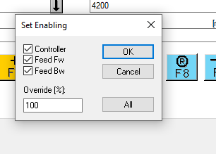
Done!Ready Flag for Mover Axis 1 is now ON.
You can check the operation from this video.
Finally, the other Mover Axis is powered on and coupled to Mover Axis 1 from the Coupling tab to create a synchronous behavior.
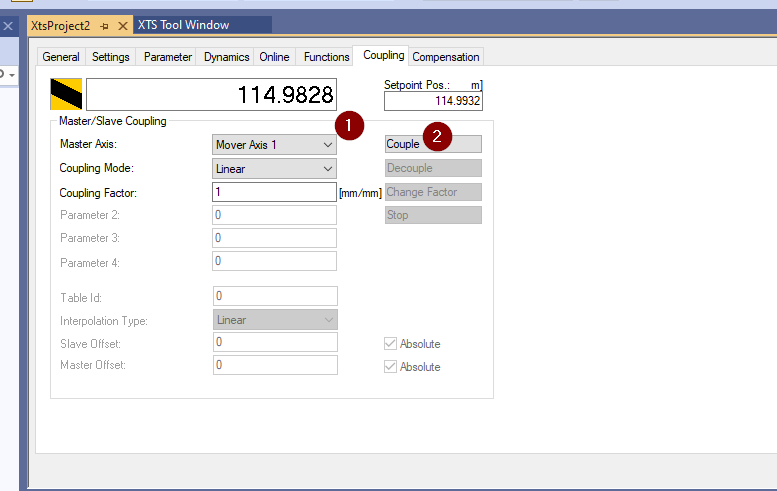
You can check the operation from this video.
コメント
Thank you man for your truly detailed explanation for XTS can’t wait for next part.