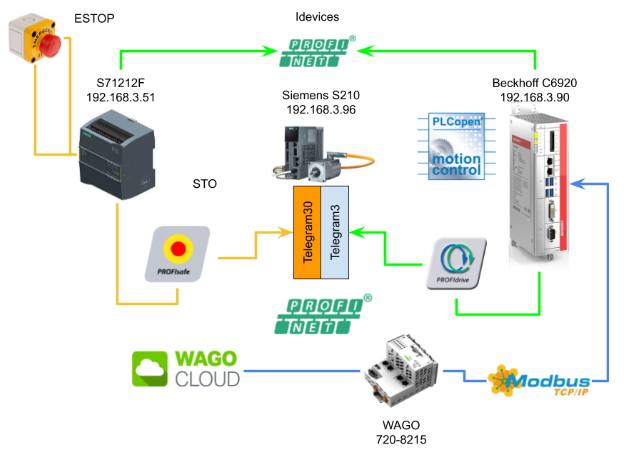
Last time, I used the Idevices function to exchange data from S71212F to Beckhoff IPC C6920 with Profinet. This time I’m going to step away from the main control and upload Beckhoff IPC data to WAGO Cloud via WAGO PFC Controller 720-8215 Modbus TCP.Let’s start!
Thanks!
Because of Beckhoff Japan ,Wago Japan and mana Design works that lend the devices to me – I can create this post.
Beckhoff Japan
IPC6920-005 was lent by Beckhoff Japan, a Japanese subsidiary of Beckhoff. Founded in 1980, Beckhoff Automation is a German company at the forefront of the introduction of open automation systems based on PC-based control technology.
Beckhoff Japan Corporation Beckhoff Automation Co., Ltd. established its head office in Yokohama in 2011 and the Nagoya office in 2017.

Here is the Home page of Beckhoff Japan.
https://www.beckhoff.com/ja-jp/
Mana Design Works
Siemens SINAMICS S210 was lent by Mana Design Works.
Mana Design Works is an official solution partner of Siemens ,headquartered in Osaka, and always make optimal proposals with Siemens CPUs, HMIs, Drives, Motion Controllers, and SCADA.

Here is the homepage of Mana Design works.
Wago Japan
750-8215 is lent by Wago Japan Co., Ltd. WAGO was started in 1951, a German company that has supported the field with the technologies of PUSH WIRE and CAGE CLAMP, and have contributed to industries around the world with terminal block technology. WAGO also has a PLC LINEUP, offering automation solutions with an emphasis on openness and flexibility.
Wago Japan Co., Ltd. is headquartered in Koto-ku, Tokyo.

Video
English Version
Part4
Beckhoff.TwinCAT3 x Siemens S210 Servo Drive part4 – Idevices Configuration.EN
Part3
Beckhoff.TwinCAT3 x Siemens S210 Servo Drive part3 – PLCOPEN to Control the Drive in TwinCAT.EN
Part2
Beckhoff.TwinCAT3 x Siemens S210 Servo Drive part2 – Shared Devices,Profisafe.EN
Part1
Beckhoff.TwinCAT3 x Siemens S210 Servo Drive part1.EN
Japanese Version
Part4
Beckhoff.TwinCAT3 x Siemens S210 Servo Drive part4 – Idevices Configuration.JP
Part3
Beckhoff.TwinCAT3 x Siemens S210 Servo Drive part3 – PLCOPEN to Control the Drive in TwinCAT.JP
Part2
Beckhoff.TwinCAT3 x Siemens S210 Servo Drive part2 – Shared Devices,Profisafe.JP
Part1
Beckhoff.TwinCAT3 x Siemens S210 Servo Drive part1.JP
Reference Link
Japanese Version
Project#Beckhoff TwinCAT3 x Siemens S210 Servo Drvie_Part2 |
English Version
Project#Beckhoff TwinCAT3 x Siemens S210 Servo Drvie_Part2 |
Project#Beckhoff TwinCAT3 x Siemens S210 Servo Drvie_Part1 |
Implementation-1
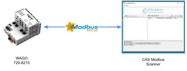
Before actually connecting with TwinCAT, it is safer to first verify the Modbus TCP Slave function of the Wago PFC Controller. A free Modbus Scanner software is used from CAS.
Reference Link
E!EOCKPIT Side
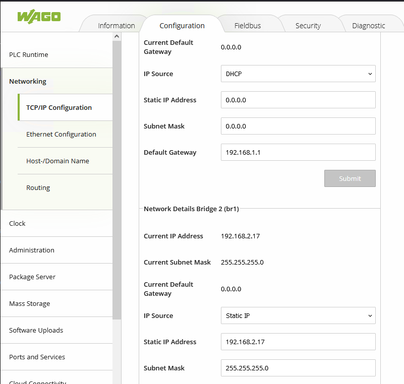
Interface configuration
We will use Port1 as the IOT port and Port2 as the data collection port.
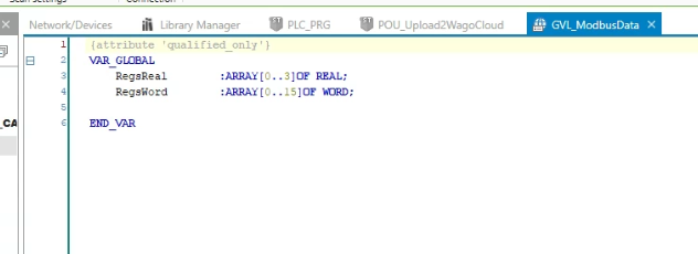
Define Variables
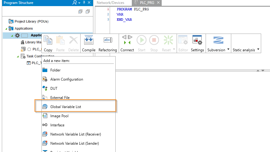
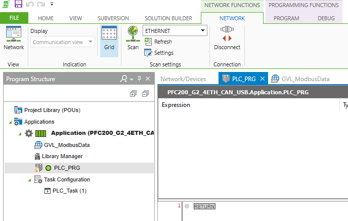
Open the Program Structure Tab.
The operation interface is very similar between E!COCKPIT and Codesys, Go to Application>Right Click>Create a Global Variable List.
Enter the GVL name>add it.
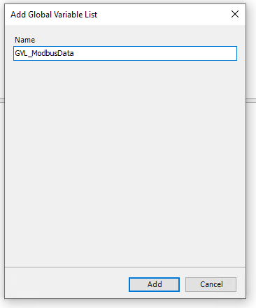
GVL is inserted in your project.
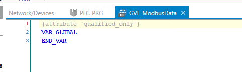
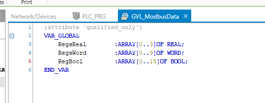
Let’s Define some Register for the modbus TCP Server.
Hardware Configuration
Now we need to build the hardware configuration.
Add Modbus TCP
Check the Network view in your E!COCKPIT tools, go to Product Catalog >Open the MODBUS TCP Folder and Scroll down.
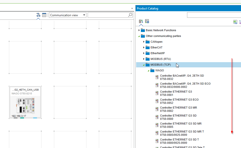
Drop the Generic_Modbus_Master into the network.
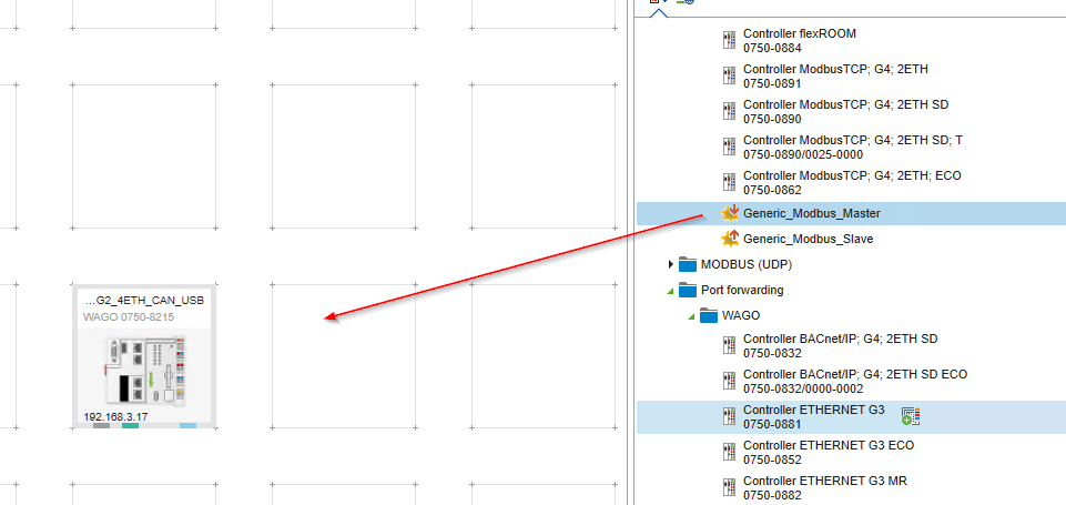
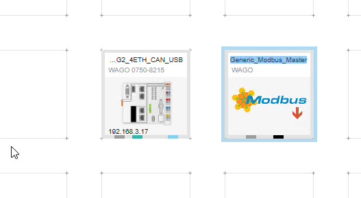
Modbus Master is inserted in your project.
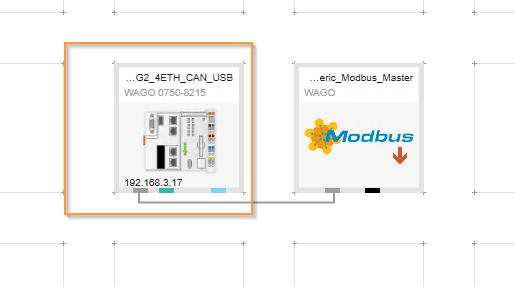
Connect it
Let’s Connect the PFC controller to the Generic_Modbus_Master.Please Click the ETHERNET(ETHERNET).

Generic_Modbus_Masterにひっばります。

Connection is configured.

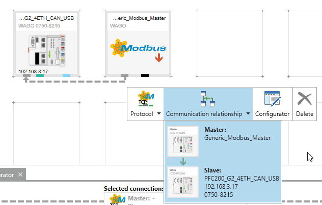
Check Communication Relationship
Just in case, click the gray LINE of Connection and click the button of Communication Relation.
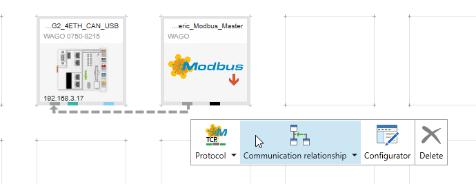
You can see that Master is Generic_Modbus_Master and Slave is PFC Controller.
Configurator
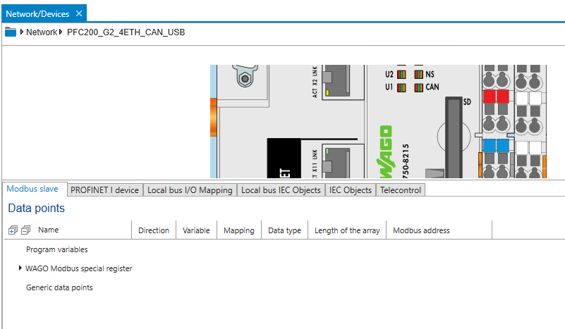
Next, click PFC Controller and set Modbus Slave.
Click the Configurator button.

Modbus Configurator is shown.
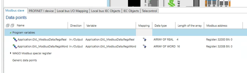
Add Program variables
Right click the Program variables>Add From program.
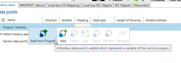
The variables currently in the E!COCKPIT project are displayed.
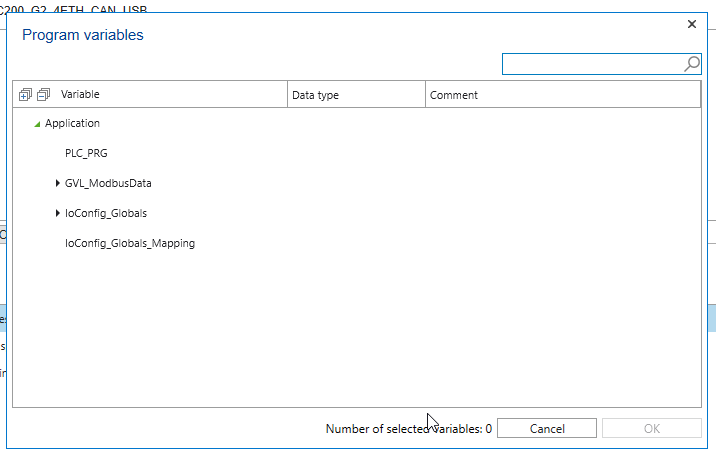
Select GVL_ModbusData > OK.

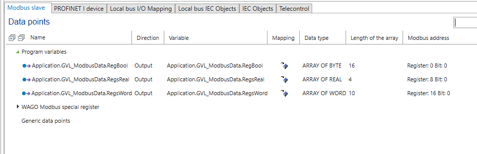
Three array variables have been added from your User Program.
Basic Settings
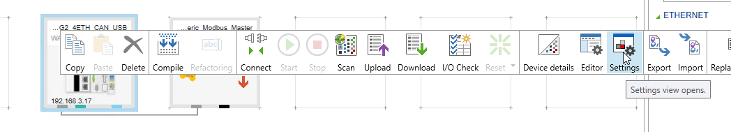
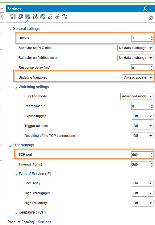
Next, right-click PFC Controller and make detailed settings for Modbus Slave from Settings button.
Set Unit-ID to 1, select Always update for Update Variables, and finally set TCP Port to 502 in TCP Settings.
Downlaod
Finally, download the project with Connect from the NETWORK Tab.

Run
Let’s switch the CPU to Run Mode.
Check it
Let’s verify the connection with the Modbus Scanner Software.
Install tools
This time we will use a free software called CAS Modbus Scanner.

Run the EXE File.
Next>.

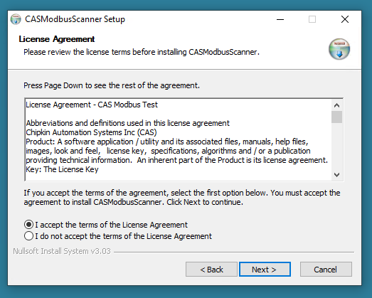
Accept the license and click Next>.
Set the Install Path and proceed with Install.

Done!

CAS Modbus Scanner started.
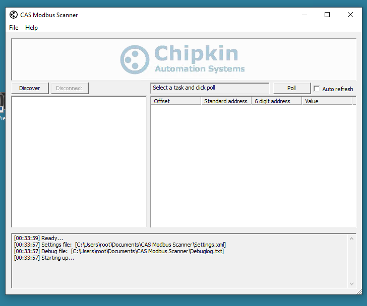
Scan it
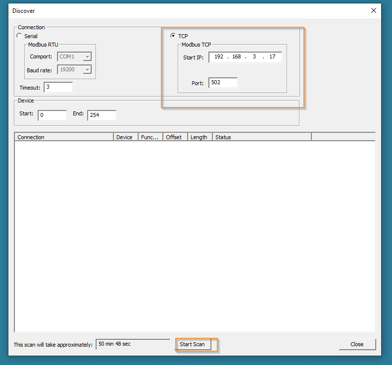
First, search for Wago Modbus Slave with the Discover function.

Select TCP Connection and set IP and Port of PFC Controller.
Press Start Scan to search the nodes.
Add Connection
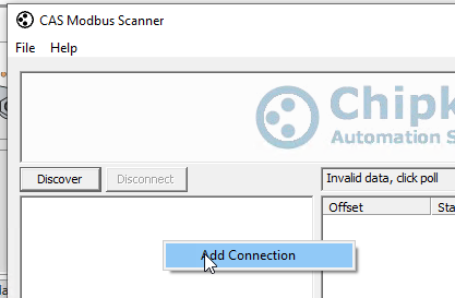
Next, let’s add a Connection.
Right click > Add Connection.
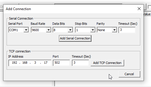
Enter the IP and Port from the TCP Connection Field, and add the PFC Controller with “Add TCP Connection”.
Next, right-click > Add Device from the Connection you just added.
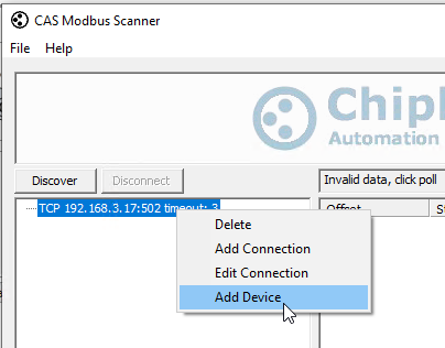
Match the Slave ID with the Unit-ID set on the E!COCKPIT side.

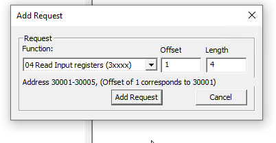
Slaves have been added. Finally, create a read task. Right-click > Add Task from Slave.

Select -Function 04, Offset 1, Length4>Add Request. If the connection is OK, 4 bytes of data can be read from 30001.
Implementation-2
E!COCKPIT Side
After the Connectivity of Modbus TCP Server is confirmed, we can implement the TwinCAT side to access the Modbus TCP Server.
Configuration
we just modify the registers in implementation-1.
And we’re-map the Register in the Modbus Editor.
Program
POU_Upload2WagoCloud
It’s not much different from the first chapter of WAGO CLOUD Tutorial, but this program collects multiple variables into one array and transfers them to WAGO CLOUD.
| PROGRAM POU_Upload2WagoCloud VAR S210_1:ARRAY[0..9]OF WagoAppCloud.typVariableDescription; S210_1_Collections:WagoAppCloud.typCollection; Logger:WagoAppCloud.FbCollectionLogger; Status:WagoSysErrorBase.FbResult; END_VAR VAR RETAIN tSampleInvTime :TIME:=T#1S; tPublishInvTime :TIME:=T#1S; END_VAR VAR bError:BOOL; bOperational:BOOL; bNotMoving :BOOL;END_VAR //ID1 S210_1[0].sUnit:=’mm’; S210_1[0].pAddress:=ADR(GVL_ModbusData.RegsReal[0]); S210_1[0].eValueType:=WagoAppCloud.VVT_REAL; S210_1[0].sTag:=’ActPos’; S210_1[0].dwTypeId:=1; //ID2 S210_1[1].sUnit:=’mm’; S210_1[1].pAddress:=ADR(GVL_ModbusData.RegsReal[1]); S210_1[1].eValueType:=WagoAppCloud.VVT_REAL; S210_1[1].sTag:=’ActVel’; S210_1[1].dwTypeId:=2; //ID3 S210_1[2].sUnit:=”; S210_1[2].pAddress:=ADR(GVL_ModbusData.RegsWord[0]); S210_1[2].eValueType:=WagoAppCloud.VVT_WORD; S210_1[2].sTag:=’Error’; S210_1[2].dwTypeId:=3; //ID4 S210_1[3].sUnit:=”; S210_1[3].pAddress:=ADR(GVL_ModbusData.RegsWord[1]); S210_1[3].eValueType:=WagoAppCloud.VVT_WORD; S210_1[3].sTag:=’Operational’; S210_1[3].dwTypeId:=4; //ID5 S210_1[4].sUnit:=”; S210_1[4].pAddress:=ADR(GVL_ModbusData.RegsWord[3]); S210_1[4].eValueType:=WagoAppCloud.VVT_WORD; S210_1[4].sTag:=’ActStationo’; S210_1[4].dwTypeId:=5; S210_1_Collections.dwCollectionId:=1; S210_1_Collections.dwVariablesCount:=5; S210_1_Collections.sName:=’S210 Data’; S210_1_Collections.pPublishInterval:=ADR(tPublishInvTime); S210_1_Collections.pSampleInterval:=ADR(tSampleInvTime); S210_1_Collections.pVariableDescriptions:=ADR(S210_1); Logger( pCollections:=ADR(S210_1_Collections) ,dwCollectionsCount:=1 ,oStatus=>Status ); bError:=GVL_ModbusData.RegsWord[0]<>0;bOperational:=GVL_ModbusData.RegsWord[1]<>0;bNotMoving:=GVL_ModbusData.RegsWord[2]<>0; |
PLC_PRG
Finally, we call the program from PLC_PRG on MAIN.
| PROGRAM PLC_PRG VAR END_VAR VAR RETAIN END_VAR POU_Upload2WagoCloud(); |
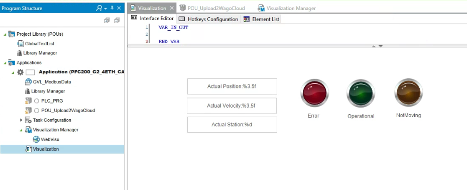
HMI
Create a simple screen on E!COCKPIT and transfer it to the PFC Controller.
The screen will be displayed in the same way on WAGO CLOUD.
TwinCAT Side
Reference Link
Add Library
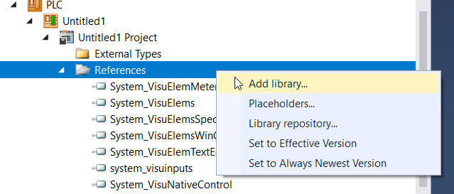
Go to PLC>References>Add Library to add a new library into your project.
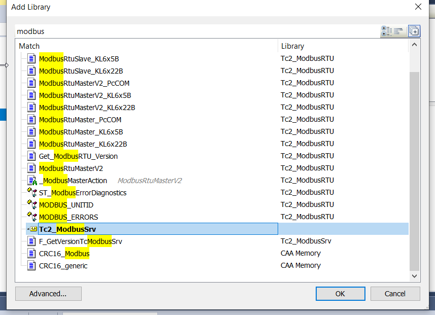
Choose Tc2_ModbusSrv>OK.
Programs
Insert this program into POU_Main and call it in main.
POU_Modbus
This is a program to communicate with MODBUS TCP Slave of Wago PFC Controller. When bStart becomes True、 communication starts > First write Real Register, then write 16 Bit Integer Register > return infinite loop.
| PROGRAM POU_Modbus VAR _MBWriteRegs :FB_MBWriteRegs; bStart :BOOL; RealRegister :ARRAY[0..3]OF REAL; R_TRIG:R_TRIG; bBusy,bError:BOOL; nErrorID:UDINT; TONs: ARRAY[0..2]OF TON; iStep:INT; END_VAR CASE iStep OF 0: IF bStart THEN _MBWriteRegs.nMBAddr:=32000; _MBWriteRegs.nQuantity:=SIZEOF(GVL_Modbus.RealRegister)/2; _MBWriteRegs.cbLength:=SIZEOF(GVL_Modbus.RealRegister); _MBWriteRegs.pSrcAddr:=ADR(GVL_Modbus.RealRegister); iStep:=10; END_IF 10: IF _MBWriteRegs.bError OR _MBWriteRegs.bBusy THEN iStep:=20; END_IF 20: TONs[0](IN:=TRUE,PT:=T#0.2S); IF TONs[0].Q THEN TONs[0](IN:=FALSE); iStep:=30; END_IF 30: IF bStart THEN _MBWriteRegs.nMBAddr:=32008; _MBWriteRegs.nQuantity:=SIZEOF(GVL_Modbus.WordRegister)/2; _MBWriteRegs.cbLength:=SIZEOF(GVL_Modbus.WordRegister); _MBWriteRegs.pSrcAddr:=ADR(GVL_Modbus.WordRegister); iStep:=40; END_IF 40: IF _MBWriteRegs.bError OR _MBWriteRegs.bBusy THEN iStep:=50; END_IF 50: TONs[0](IN:=TRUE,PT:=T#0.2S); IF TONs[0].Q THEN TONs[0](IN:=FALSE); iStep:=0; END_IF END_CASE _MBWriteRegs( sIPAddr:=’192.168.3.17′ ,bExecute:=iStep = 10 OR iStep=40 ,nTCPPort:=502 ,nUnitID:=16#FF ,bBusy=>bBusy ,bError=>bError ,nErrId=>nErrorID ); |
MAIN
In the MAIN POUs, we will call the previous POU_Modbus, and transfer the data of S210/S71200 to Real Register and 16Bit Integer Register.
| PROGRAM MAIN VAR Axis :AXIS_REF; END_VAR VAR PNController :FB_PNController_Status; PNDevices_S210 :FB_PnDevices_Status; PNDevices_S71200:FB_DataFromSiemens; S210 :FB_MyS210; Mode :eDUT_Mode; autocmd:BOOL; autosst :DINT; istep:DINT; TON :TON; END_VAR IF NOT PNDevices_S71200.STOOK THEN istep:=0; GVL_SystemHMI.PB.AutoStart:=FALSE; autosst:=0; END_IF GVL_SystemHMI.PL.ModeAuto:=GVL_SystemHMI.PB.Mode = eDUT_Mode.Auto; GVL_SystemHMI.PL.ModeManual:=GVL_SystemHMI.PB.Mode = eDUT_Mode.Manual; GVL_SystemHMI.PL.Reset:=GVL_SystemHMI.PB.Reset; GVL_SystemHMI.PL.PowerOn:=S210.qStatus.Operational; GVL_SystemHMI.PL.AutoStart:=istep<>0; IF GVL_SystemHMI.PL.ModeAuto THEN Mode:=eDUT_Mode.Auto; ELSIF GVL_SystemHMI.PL.ModeManual THEN Mode:=eDUT_Mode.Manual; END_IF; IF Mode=eDUT_Mode.Auto THEN CASE istep OF 0: TON(IN:=GVL_SystemHMI.PB.AutoStart,PT:=T#1S); IF TON.Q THEN istep:=10; TON(in:=False); END_IF 10: autosst:=1; IF S210.qActualStation = 1 THEN istep:=15; autosst:=0; END_IF 15: TON(in:=TRUE,PT:=T#1S); IF TON.Q THEN TON(in:=FALSE); istep:=20; END_IF; 20: autosst:=2; IF S210.qActualStation = 2 THEN istep:=10; autosst:=0; END_IF END_CASE ELSE istep:=0; autosst:=0; END_IF PNDevices_S71200.Reset(Execute:=GVL_SystemHMI.PB.Reset); S210.iPNComOK:=PNController.Ready AND PNDevices_S210.Ready AND PNDevices_S71200.Ready ; S210( iEnable:=TRUE ,bServoON:=GVL_SystemHMI.PB.PowerOn ,bReset:=GVL_SystemHMI.PB.Reset ,Mode:=Mode ,bILAbs:=TRUE ,bILJog:=TRUE ,bILAbs:=TRUE ,bAutoAbsCmd:=autocmd ,iAutoStationCmd:=autosst ,Hmis:=GVL.Hmis ); GVL_Modbus.RealRegister[0]:=S210.qActualPosition; GVL_Modbus.RealRegister[1]:=S210.qActualVelocity; GVL_Modbus.WordRegister[0].0:=S210.qStatus.Error; GVL_Modbus.WordRegister[1].0:=S210.qStatus.Operational; GVL_Modbus.WordRegister[2].0:=S210.qStatus.NotMoving;; GVL_Modbus.WordRegister[3]:=UDINT_TO_WORD(s210.qActualStation); POU_Modbus(); |
Wago Cloud Side
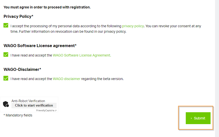
To be able to display the PFC Controller screen from WAGO CLOUD、 you need to install a little Plug-in.
Download Package
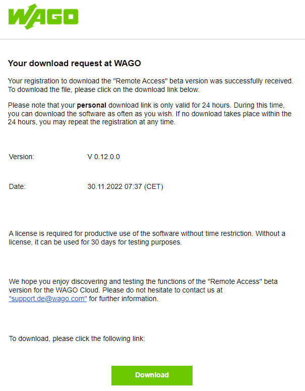
Access the below link and enter the information>Submit.
Press the Download BUtton to Download the Software Packages.
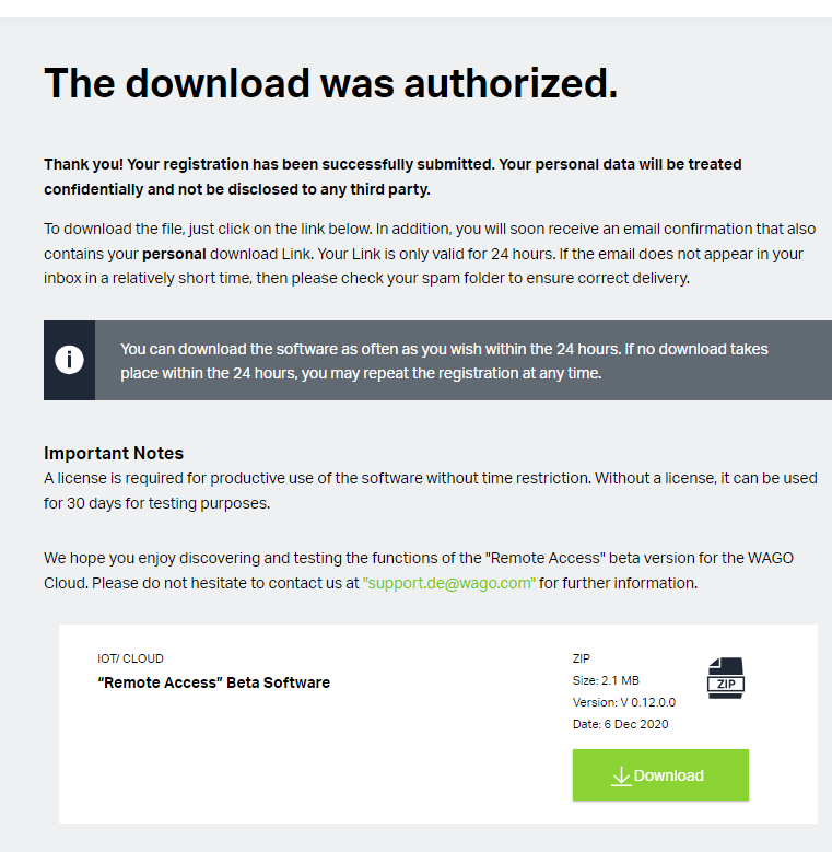
Alternatively、 you can also download it from here as you will receive a Download Link from your email.
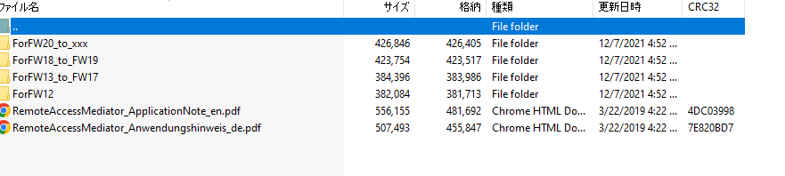
A Zip file is downloaded.
Software Packages of each PFC Controller ‘s firmware are zipped inside.
Install Software
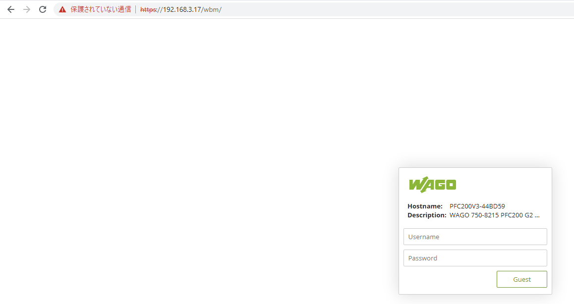
Next、 let’s install Software Packages to the PFC Controller. Please access the WBM of the PFC Controller.
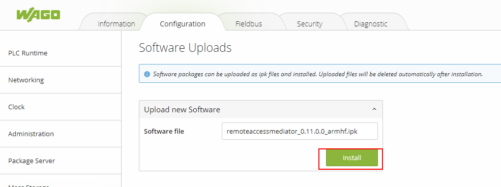
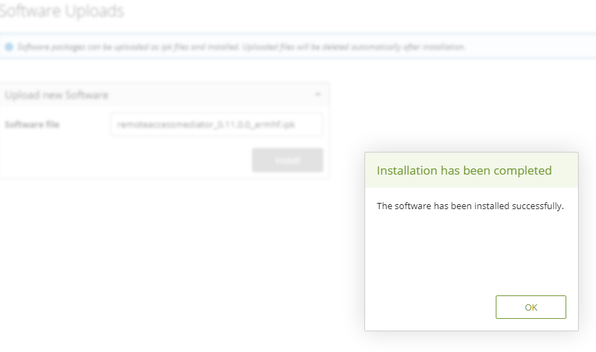
Go to Software Update>Click the Software File.

My PFC Controller’s firmware is higher than 20 and FW20UP Software Packages is chosen in here.

Press the install button to install the Software Packages.
Please wait a minute..
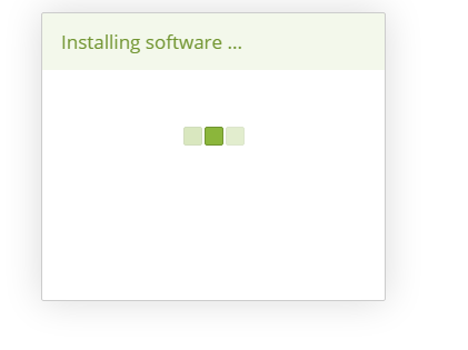
Done!
Restart
Let’s restart your Wago PFC Controller.
Result
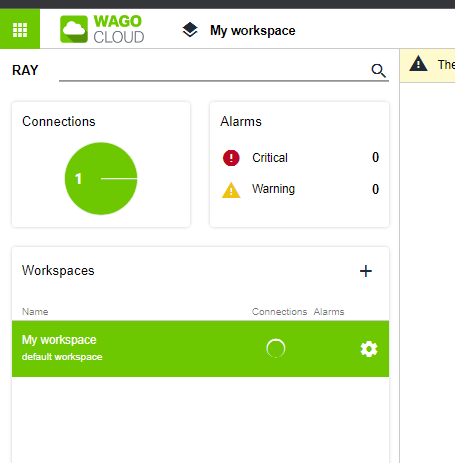
Status
The status is shown as Critical if the connection is not established.

Online status is shown while the connection is established!
Collection
And we can see the S210 Data Collection is inside our collection.

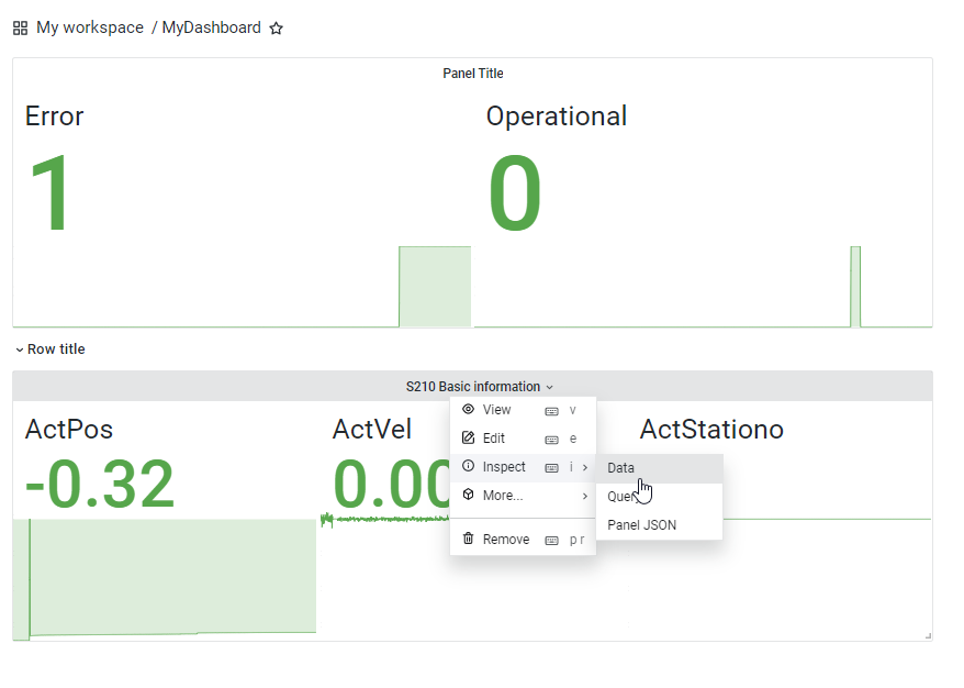
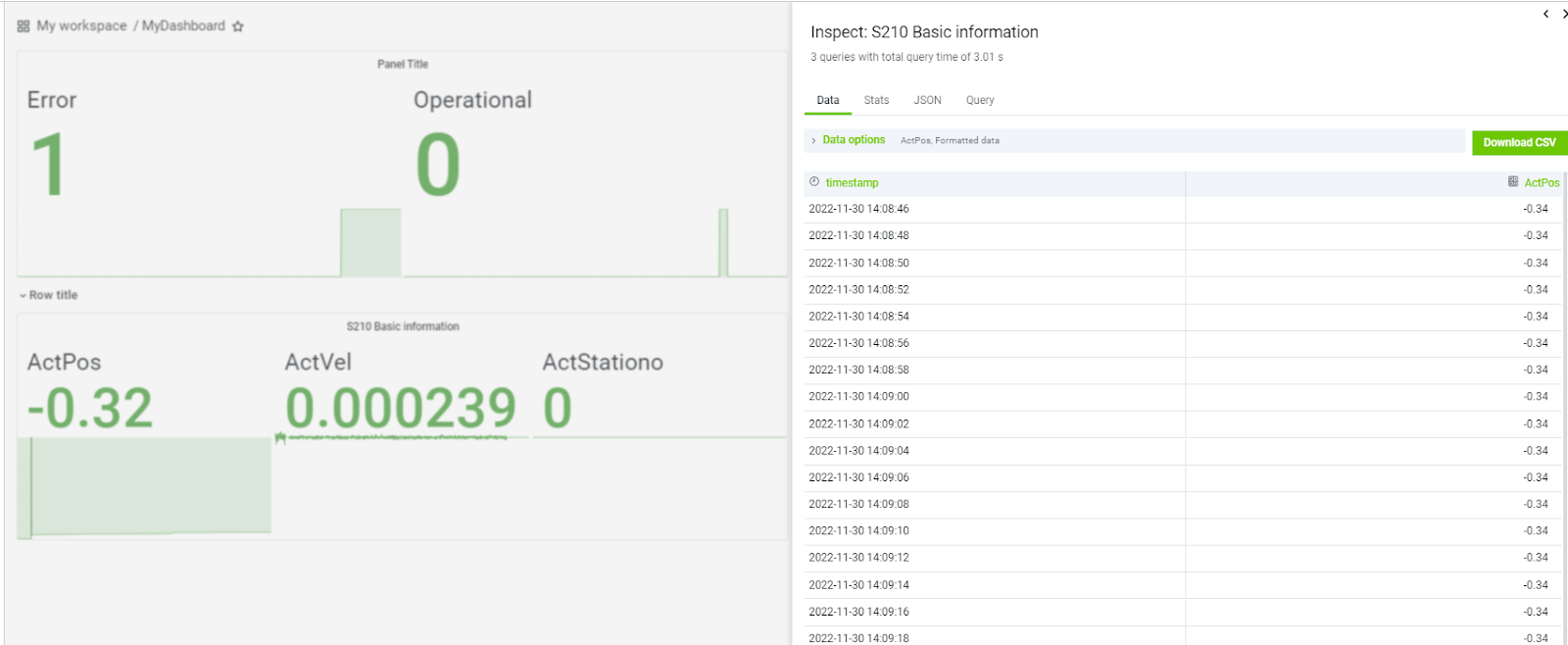
Dashboard
And we can see the Speed/Error status in the Dashboard;)

If you want to list the data of the time column, click from the Dashboard Title>Inspect>Data.
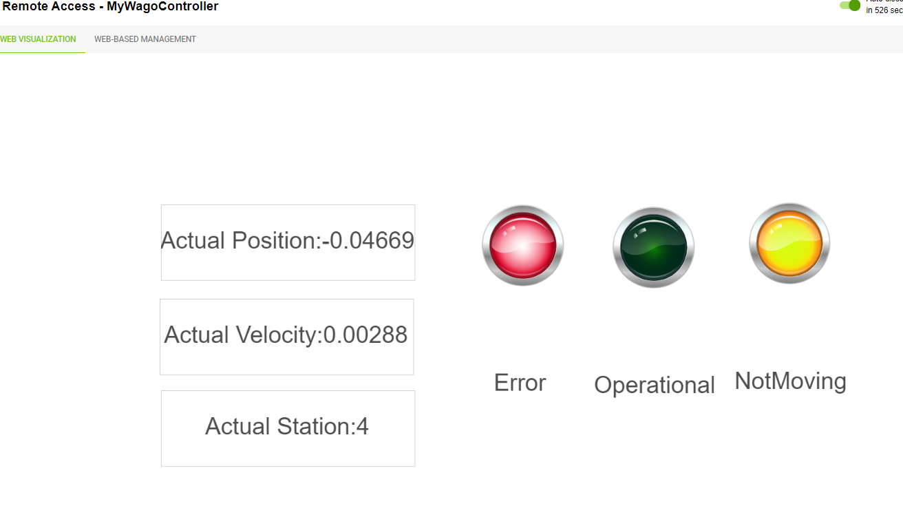
HMI
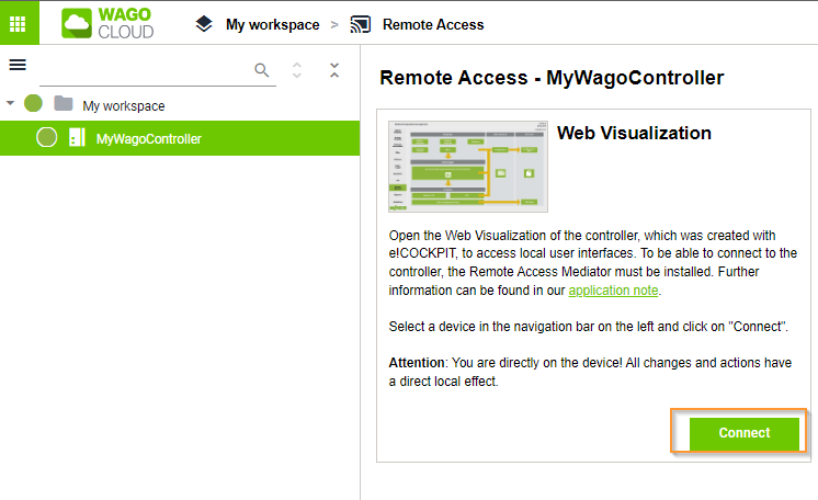
The last is the HMI. The “Connect” button for Web Visualization and Web-based Management from Remote Access is now in green!
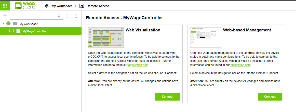
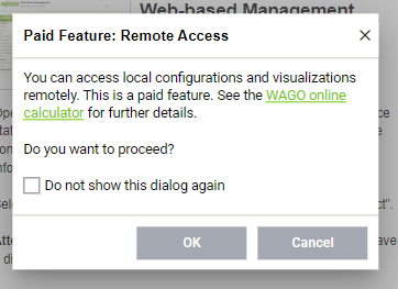
First, let’s take a look at the Web Visualization of the PFC Controller.
OK.
Username and Password are the same as WBM.

Done!
You can also see the PFC Controller Web Browser in Wago Cloud. In other words, it is possible to change the settings of the PFC Controller from Wago Cloud.

Video
Source Project Download
https://github.com/soup01Threes/TwinCAT3/blob/main/TwinCAT%20S210-part5.zip