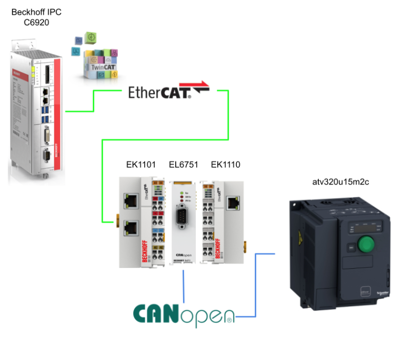
In this article, I will use Beckhoff EL6751 to start CANOPEN Master and communicate with Schneider’s ATV320 over CAN.
Let’s Start!
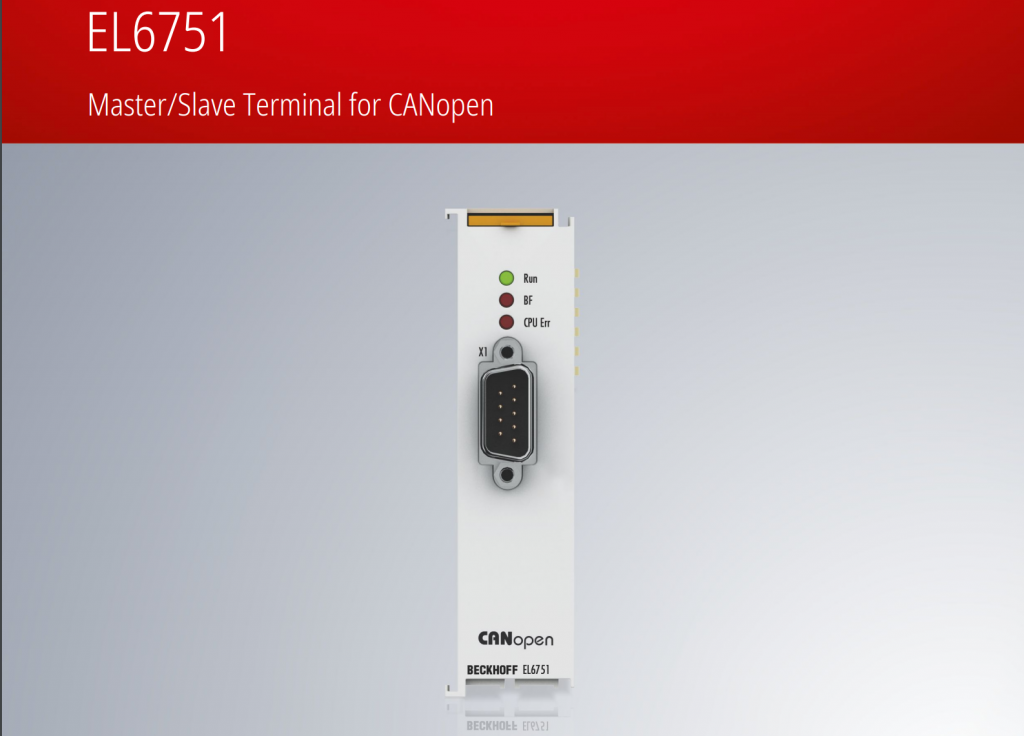
EL6751?
The EL6751 is a terminal with CANOPEN Master or Slave functionality and can communicate with any CANOPEN device in the EtherCAT network. In addition, it eliminates the need to send and receive general CAN messages in the application program.
The EL6751 provides the following basic functions
- Supports all CANopen PDO communication types
- event-controlled
- time-controlled (event timer),
- synchronous.
- Synchronized with PC controller task cycles
- Parameter communication (SDO) support at startup and runtime
- Emergency message handling/guarding/heartbeat support
- Parameter and diagnostic interfaces
- Online bus load display
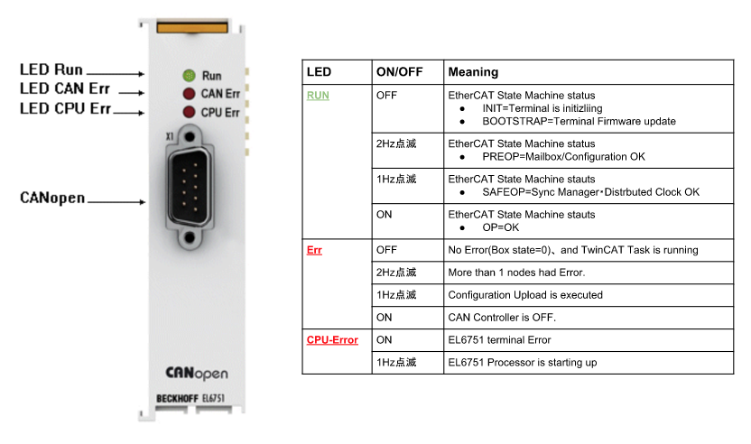
Layout
Here is an explanation of the meaning of Layout and LEDs in EL6751.
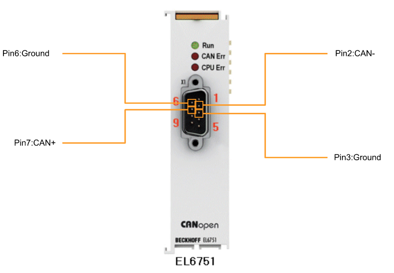
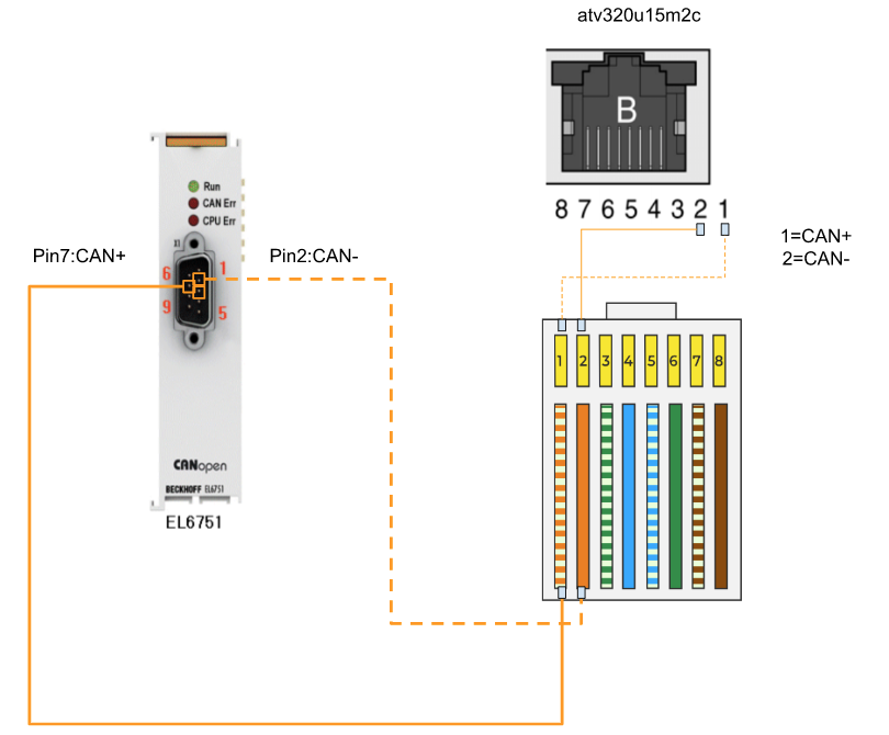
Wiring
Here are the wires, Pin 2 is CAN-, Pin 7 is CAN+, and Pin 3 and Pin 6 are internally connected CAN Ground.
CAN OPEN
CANopen manages communication between network devices with object dictionaries and objects. Network devices can request object data from other devices’ object dictionaries or write back changed values using process data objects (PDOs) and service data objects (SDOs).
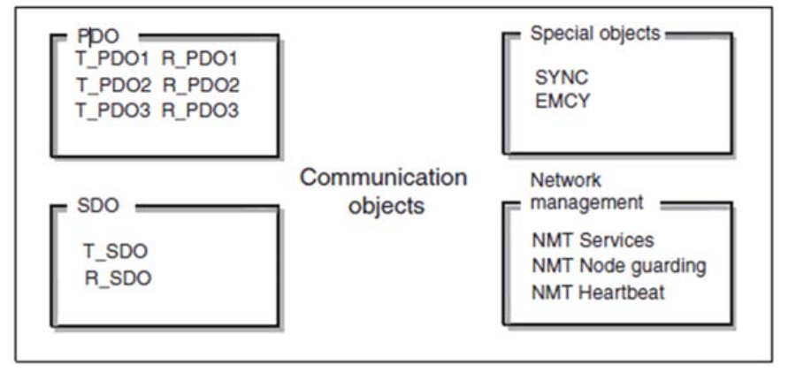
PDOs (process data objects)
Transmits process data in real time.
SDOs (service data object)
Read and write object dictionaries.
SYNC object (synchronization object)
Synchronize network devices.
EMCY object (emergency object),
Signal error of the device or its peripherals.
NMT services
Network control
NMT node guarding
Monitor network devices.
NMT heartbeat
Monitor network devices.
Reference Link
CIA402
CIA402 is a profile of drive control functions operating on the CANopen network and is the standard for controlling Electrically Driven Machinery, or EDM. The profile defines a CANopen object dictionary and specifies the CAN messages required for exchanging control commands and feedback information. CIA402 is dedicated to motion control applications, allowing for motor position, velocity, acceleration, and torque control.
Control devices compliant with CIA402 can communicate with each other via the same protocol, CANopen, and thus have the advantage that control devices from different manufacturers can be combined and operate without problems. In addition, the standard-based design ensures compatibility of control devices, allowing for more flexible design and system expandability.
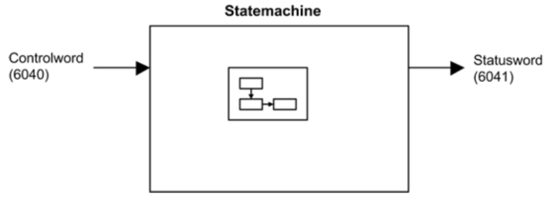
The main parameters of the ATV320 Index are as follows. () is the corresponding CANOPEN address, e.g. Controlword is 6040 and StatusWord is 6041. The figure below shows the control diagram for drive operation:
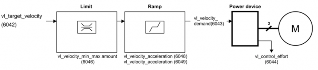
Below is a simplified diagram in speed control mode.
Index 6041 Statusword
- Bit 0 : Ready to switch on, 1 = waiting for power supply
- Bit 1 : Switched on、1=Ready
- Bit 2 : Operation enabled、1=Running
- Bit 3 : Fault、1=Error
- Bit 4 : Voltage enabled, 1=power on
- Bit 5 : Quick Stop、0=Quick Stop is enabled
- Bit 6 : Switch on disabled、1=Power is not available
- Bit 7 : Warning、1=Warning
- Bit 8 : reserved
- Bit 9 : Remote, whether the device is controlled from Fieldbus or not.
- Bit 10:Target Reached, 1=Speed command value reached
- Bit 11 : Internal limit active
- Bit 12-13 : reserved
- Bit 14 : Manufacturer-specified STOP Flag
- Bit 15 : Manufacturer-specified Direction Flag
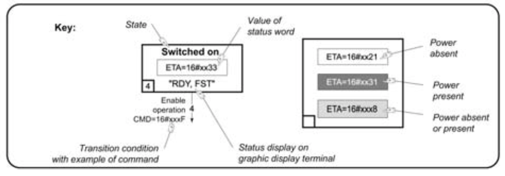
Operation State
The operational status of the drive changes depending on whether a Control Word is sent or an event occurs, such as an error. The current state of the drive can be identified by the value of the Status Word.
1 – Not ready to switch on
Initialization is initiated. It is a transient state, hidden from the communication network.
2 – Switch on disabled
The power stage cannot be switched on. The drive is locked and the motors are not powered. If it is an independent control stage, it does not need to be powered, but if it is an independent control stage with a mains contactor, its outlet is not closed. You can change the parameters for adjustments and settings.
3 – Ready to switch on
The Power stage is ready to be switched on and is waiting for the main power supply of the power stage. In the case of an independent control stage, the power stage does not need to be supplied, but the system after it is waiting for the power stage to be supplied in order to transition to state 4 – Switched on.
For independent control stages with a mains contactor, the contactor is not closed. The drive is locked and no power is supplied to the motor. The parameters for adjustments and settings can be changed.
4 – Switched on
The power stage is switched on and, for independent control stages, power must be supplied to the power stage. For independent control stages with the main power contactor, the contactor is closed. The drive is then locked and power is not supplied to the motor. The drive’s power stage is ready for operation, but no voltage is yet output to the outputs.
The parameters of the adjustments and settings can be changed, and if they are changed, the drive will return to State 2 – Switch on disabled.
.
5 – Operation enabled
The power stage is enabled and the drive is in running state. If it is an independent control stage, the power stage must be supplied. If it is an independent control stage with a mains contactor, the contactor is closed.
The drive is then unlocked and power is supplied to the motor.
The drive function is activated and voltage is supplied to the motor terminals.
If the reference value is zero or a stop command, no power is supplied to the motor and no torque is generated. To execute [Auto tuning], the drive must be in state 5 – operational.
The tuning parameters can be changed, but the configuration parameters cannot be changed.
6 – Quick stop active
The drive performs a rapid stop and remains locked in operating state 6-quick stop active. Before the motor can be restarted, it must be shifted to operating state 2-switch on disabled.
While the drive is in quick stop, the drive is unlocked, but power is still supplied to the motor. Configuration parameters cannot be changed.
7 – Fault reaction
This is when the error is detected and then moved to 8-Fault.
8 – Fault
The power stage is disabled, the drive is locked, and no power is supplied to the motor.
Index 6040 Controlword
- Bit 0 : Switch on, controls the Main Contactor
- Bit 1 : Enable voltage, authorizes AC power supply
- Bit 2 : Quick Stop active, 0=Quick Stop in use
- Bit 3 : Enable operation, 1=Run command
- Bit 4 – 6 : Standby
- Bit 7 : Fault reset, reset Fault on startup
- Bit 8 : Halt
- Bit 9 – 10 : Spare
- Bit 11 – 15 : Manufacturer’s designation
Command Example
- ShutDown
- Move to Status “3-Ready to Switch On”
- Command Example:0006HEX
- SwitchOn
- Move to Status “4-Switched On”
- Command Example:0007HEX
- Enable Operation
- Move to Status “5-Operation enabled”
- Command Example:000FHEX
- Disable Operation
- Move to Status “4-Switched on”
- Command Example:0007HEX
- Disable voltage
- Move to Status “2-Switch on disabled”
- Command Example:0000HEX
- Quick Stop
- Move to Status “6-Quick Stop Active” or “2-Switch on disabled”
- Command Example:0002HEX
- Fault Reset
- Move to Status “2-Switch on disabled”
- Command Example:0080HEX
State Diagram
State Diagram in CIA 402.
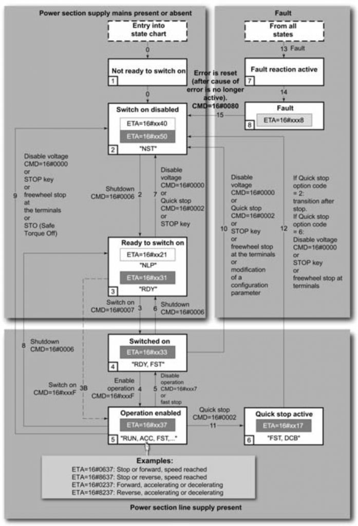
How to read it?
Implementation
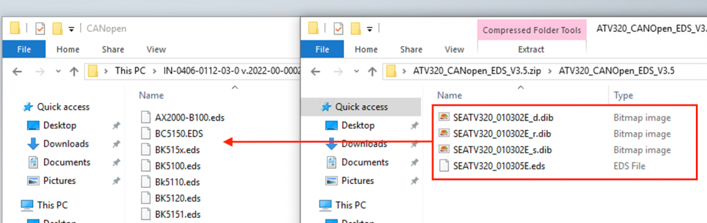
Download EDS File
Download the EDS File for ATV320 from the link below.
https://www.se.com/in/en/download/document/ATV320_CANopen_EDS_V2.9/

Configuration
Wiring
Here is the wiring for the EL6751 and ATV320.
ATV320 Side
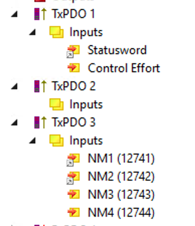
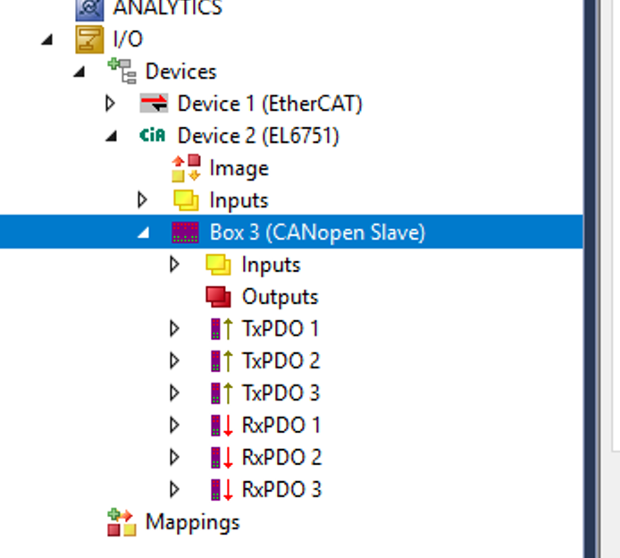
Process Data
The first PDO defaults to PDO1 in Velocity mode of the CiA402. It is asynchronous and contains two sets of data: the output Control Word (6040 hex, CMD) and target velocity (6042 hex, LFRD) and the input Status Word (6041 hex, ETA) and current velocity value (6044 hex, RFRD).
The second PDO set (PDO2) is disabled by default and still configurable (Word from 1 to 4). It is available for coordination and for additional control and monitoring functions.
The third PDO set (PDO3) is deactivated by default and cannot be set or configured: RPDO3 (Receive), containing the four output words of the communication scanner (NC1 to NC4),
TPDO3 (transmit), containing the four input words of the communication scanner (NM1 to NM4).
Parameters
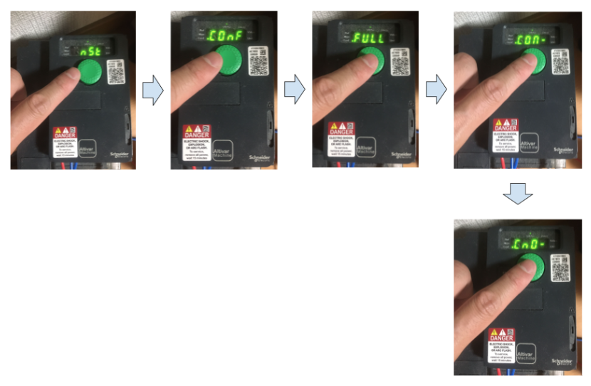
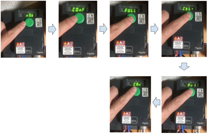
Communicaions
First, configure the communication settings for Can Open. Go to the NST>ConF>FULL>CON>Cn0 Menu as shown below.
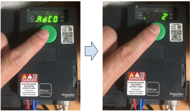
Address
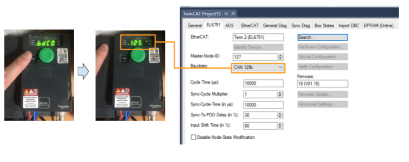
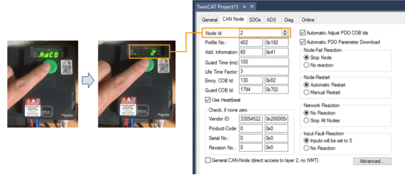
Set the CANOPEN Slave address of the ATV320, open Adc0 > this time set it to 2.So the CAN OPEN Slave address of this ATV320 is 2.
This Adc0 parameter corresponds to Modbus address 6051.
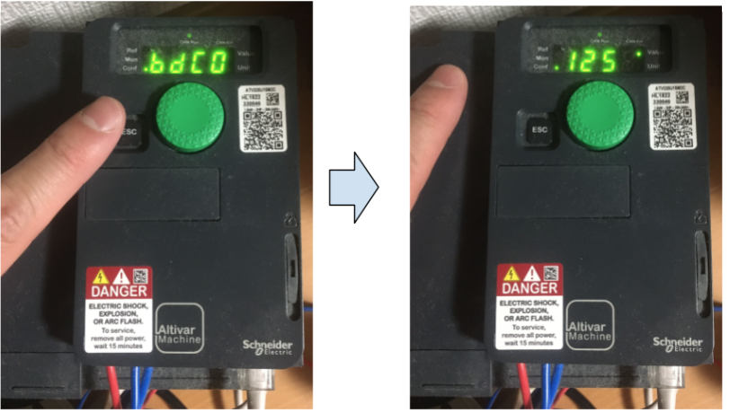
Baudrate
Next, set the CAN OPEN communication speed for the ATV320. bdc0 Open Menu. This time, set it to 125. This means the communication speed is 125k.
The bdc0 parameter here corresponds to Modbus address 6053.
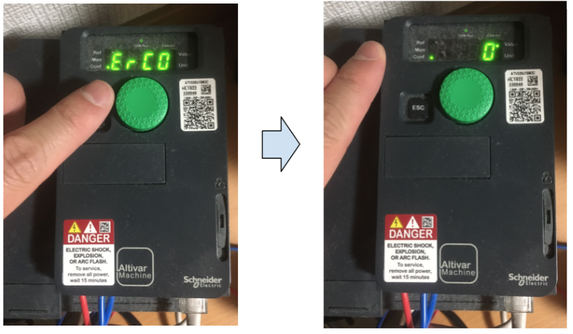
Error Code
This Menu is read-only, but if you open the ErC0 Menu to see the current error code of the ATV320. Right now it is 0, which means no error.
The ErC0 parameter here corresponds to Modbus address 6056.
Here is a list of Error Codes. And CoF is displayed when a CAN communication error occurs.
| Code | Description |
| 0 | No errors in CANOPEN communication |
| 1 | CAN Overun/Bus OFF |
| 2 | Node Guarding error |
| 3 | CAN Overrun |
| 4 | Heartbeat Error |
| 5 | NMT states Chart error |
Setpoint Reference
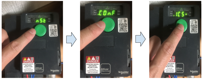
Next, change the ATV320 Setpoint reference value to refer from the CANOPEN network. Go to the NST>ConF>FULL>CTL>Fr1 Menu and change the Fr1 value to CAn as shown below.
Scanner Inputs
Check or change the Mapping of the 8 Bytes CAN input data. Go to NST>ConF>ICS- as shown below.
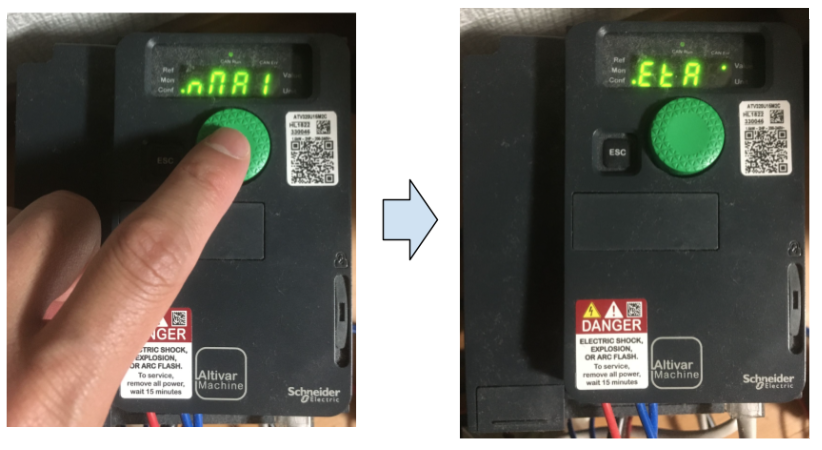
rNA1
Open rNA1Menu and the current value is ETA, where ETA corresponds to the State Register of CIA402.
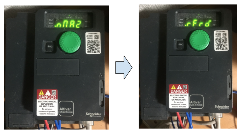
rNA2
Open rNA2Menu, current value is rFrd, ETA corresponds to the State Register of CIA402.
rFrd is INT (Signed16), the current ATV320 speed output value. (-32767 rpm … 32767 rpm)
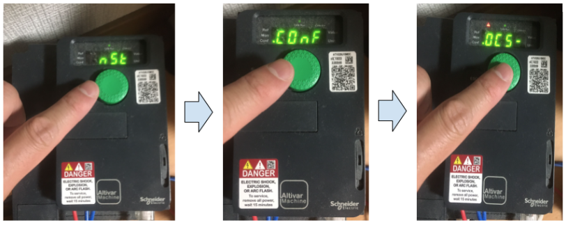
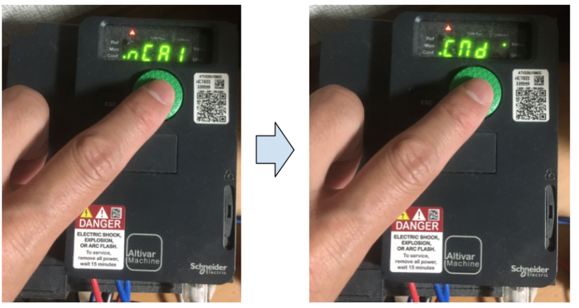
Scanner Outputs
Check or change the Mapping of the 8 Bytes CAN output data. Go to NST>ConF>OCS- as shown below.
nCA1
Open nCA1Menu, the current value is CMD; ETA corresponds to the command register of CIA402.
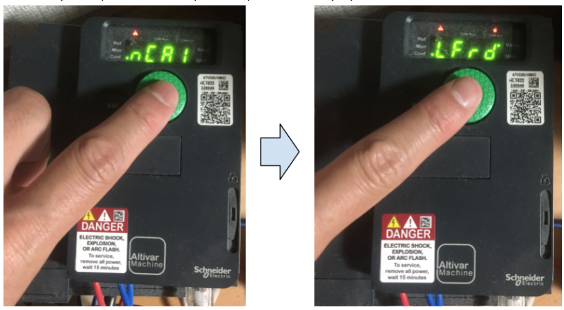
nCA2
Open nCA2Menu, current value LFrD is the speed set point, LFrD is INT (Signed16), ATV320 speed specified value. (-32767 rpm … 32767 rpm)
TwinCAT Side
Install the EDS File
Move the EDS File to the following Path.
C:\TwinCAT\3.1\Config\Io\CANopen
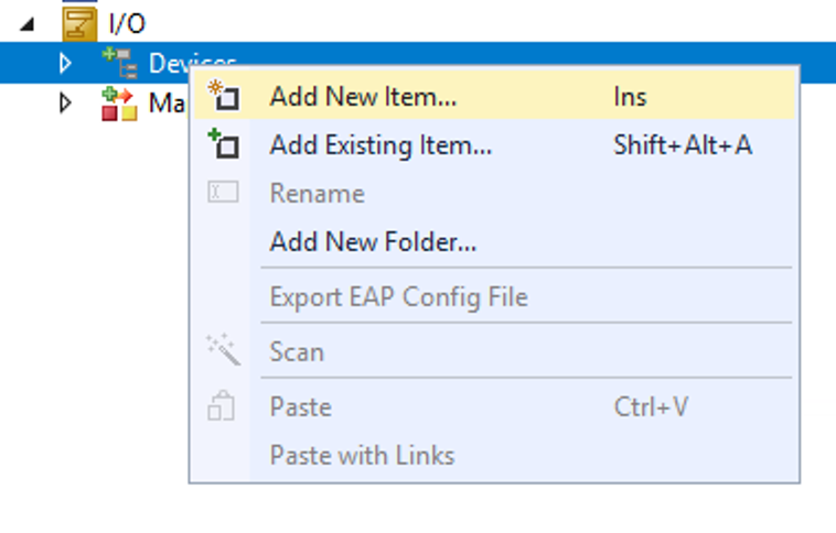
Add EtherCAT Master
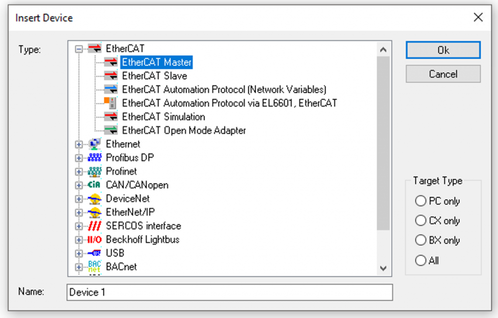
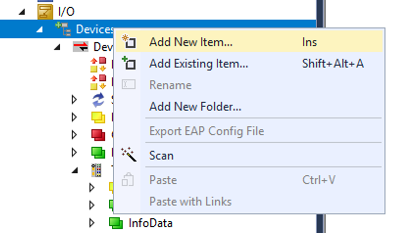
Add a new device at I/O>Devices>Add New Item.
Select EtherCAT>EtherCAT Master>Ok.
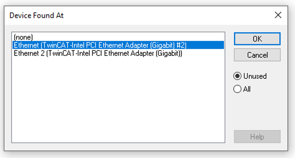
Select the LAN CARD of the EtherCAT Network to which you are now connected and press OK.
Add EK1101
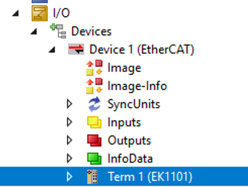
Next, add the EK1101: Device1>Right click>Add New Item.
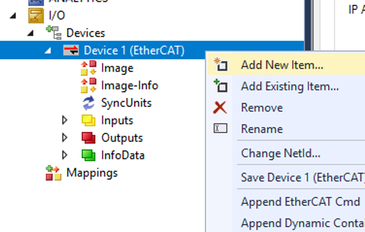
Select EK1101 >Ok.
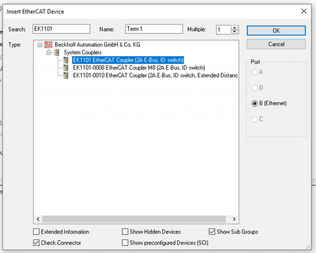
Okay, EK1101 has been added.
Add EL6751
Add EL6751 CAN Master Terminal: right click on Term1 (EK1101) > Add New Item.
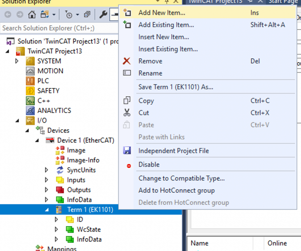
Select EK6751 >OK to proceed.
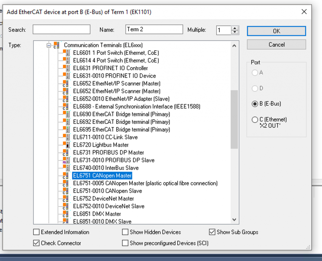
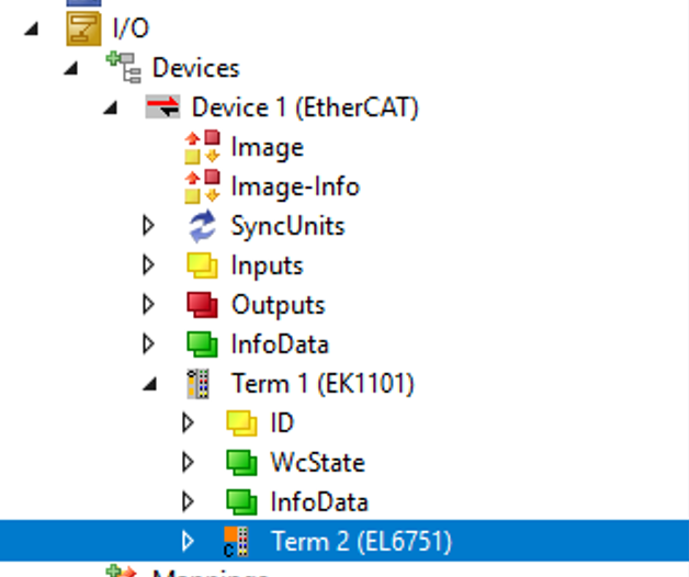
Done!
Add CanOpen Master
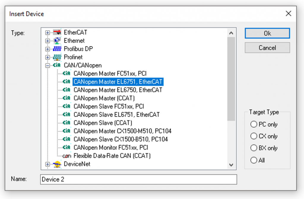
Add Canopen Master from Devices>Right click>Add New Item.
Select CANopen Master EL6751,EtherCAT >Ok to proceed.
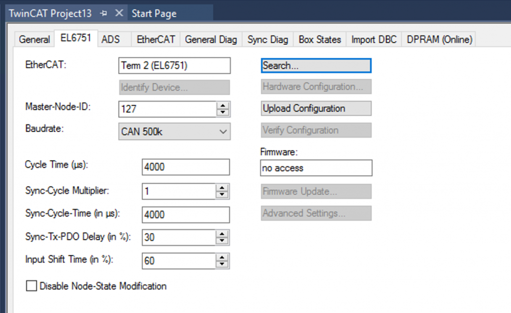
EL6751 is added and the Field of EtherCAT automatically linked to Term 2 (EL6751).
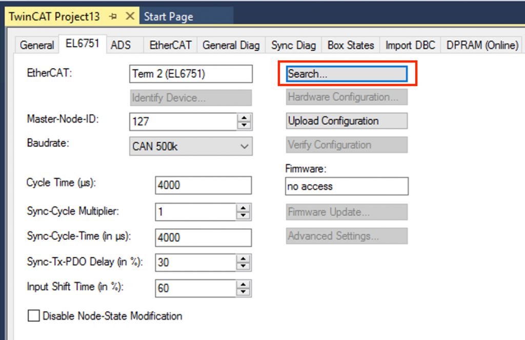
If there are multiple EL6751 Terminals, you can use the Search button to select the Terminal you wish to Link.
Baudrate
Set the Baudrate to match the actual CAN Network.
Add ATV320
Next, add Schneider’s ATV320.
Select Schneider Electric>ATV320_V3.5… and press >Ok to proceed.
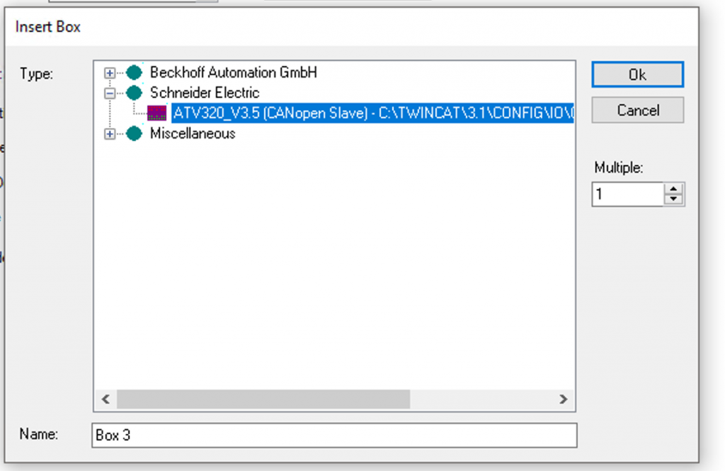
ATV320 CAN Slave has been added.
Configuration
Once the ATV320 is added, the CAN Node configuration screen will appear automatically.
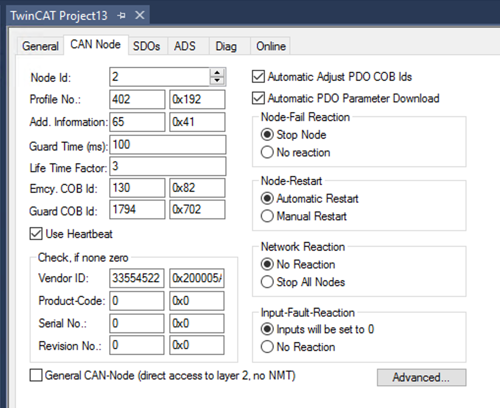
Address
Match the CAN Node ID to the ATV320 setting.
Add PLC
PLC>right click>Add New Item.
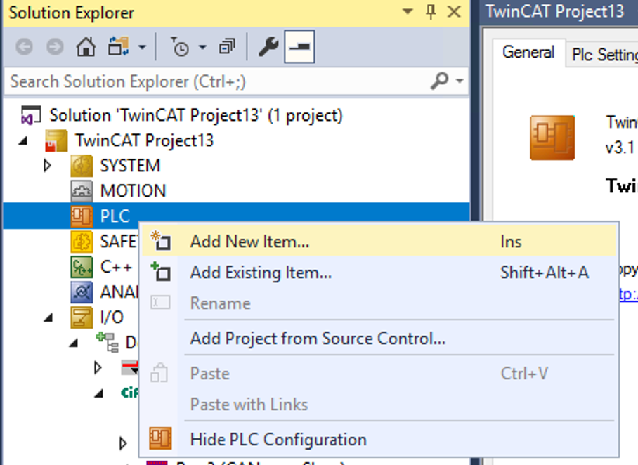
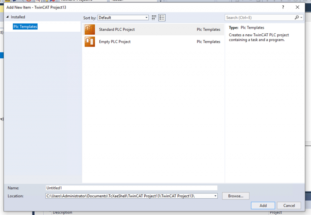
Add a new PLC project at Standard PLC Project>Add.
Program
Now we can create the program.
Interfaces
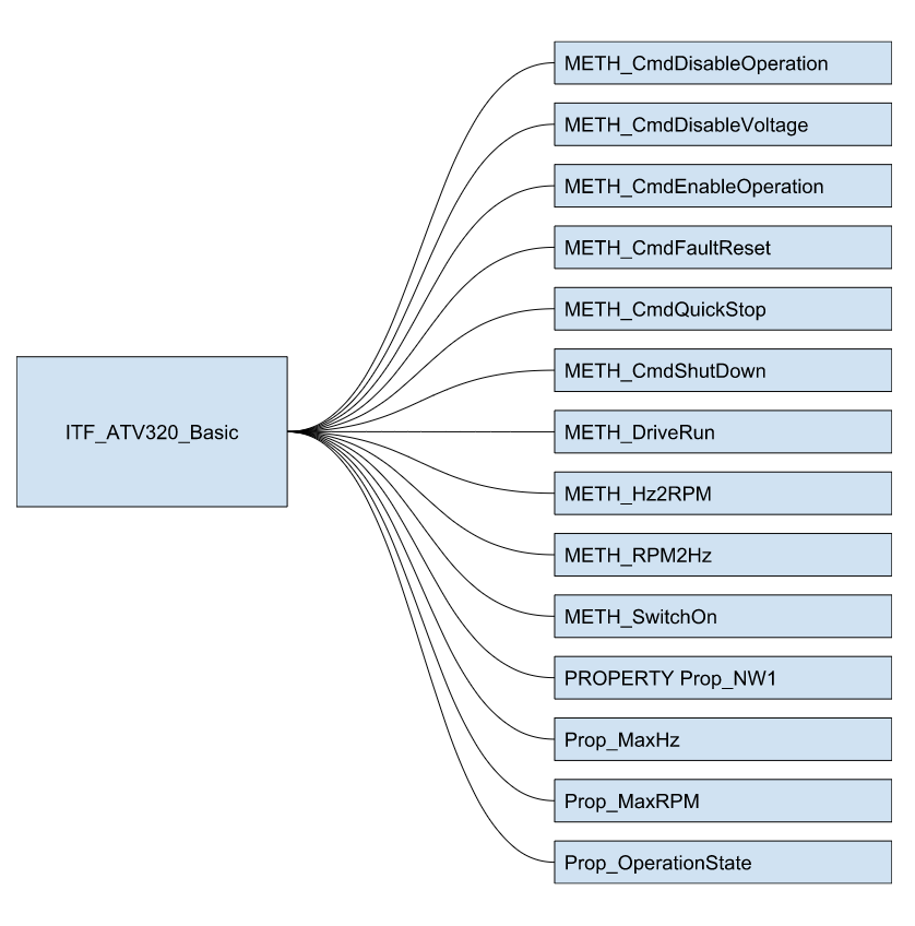
ITF_ATV320_Basic
This is the Interface of the Function Block that controls the ATV320.
DUT
The next step is to define the structure.
DUT_ATV320_NC1_CMD
This is the structure of the ATV320 Control word.
| TYPE DUT_ATV320_NC1_CMD : STRUCT b00SwitchON :BIT; b01EnableVoltage :BIT; b02QuickStop :BIT; b03EnableOperation :BIT; b04,b05,b06 :BIT; //Reserved b07FaultReset :BIT; b08Halt :BIT; b09,b10 :BIT; //Reserved b11,b12,b13,b14,b15 :BIT; //Manufacturer specific assignable END_STRUCT END_TYPE |
DUT_ATV320_NW1_ETA
This is the structure of the ATV320 Status word.
| TYPE DUT_ATV320_NW1_ETA : STRUCT b00Ready2SwitchON :BIT; b01SwitchON :BIT; b02OperationEnabled :BIT; b03Fault :BIT; b04VoltageEnabled :BIT; b05QuickStopped :BIT; b06SwitchONDisabled :BIT; b07Warning :BIT; b08 :BIT; b09Remote :BIT; b10TargetReached :BIT; b11InternalLimitActive :BIT; b12,b13 :BIT; b14StopKeyFromManufacturer :BIT; b15DriectionFromManufacturer :BIT; END_STRUCT END_TYPE |
e_ATV320_OperationState
This structure represents the state of the ATV320.
| {attribute ‘qualified_only’} {attribute ‘strict’} TYPE e_ATV320_OperationState : ( None :=0 ,NoReady2SwitchOn :=1 ,Switched2Disabled :=2 ,Ready2SwitchOn :=3 ,SwitchedOn :=4 ,OperationEnabled :=5 ,QuickStoppedActivate :=6 ,FauleReactionActivate :=7 ,Fault :=8 ); END_TYPE |
u_ATV320_NC1_CMD
Define Control word and UINT to have the same Memory offset in UNION type.
| TYPE u_ATV320_NC1_CMD : UNION raw :UINT; CMD :DUT_ATV320_NC1_CMD; END_UNION END_TYPE |
u_ATV320_NW1_ETA
Define Status word and UINT to have the same Memory offset in UNION type.
| TYPE u_ATV320_NW1_ETA : UNION raw :UINT; ETA :DUT_ATV320_NW1_ETA; END_UNION END_TYPE |
Function Block
FB_ATV320_Basic
Next, let’s create a Function Block for basic control.
| FUNCTION_BLOCK PUBLIC FB_ATV320_Basic IMPLEMENTS ITF_ATV320_Basic VAR_INPUT END_VAR VAR_OUTPUT END_VAR VAR _OperationState :e_ATV320_OperationState; _MaxHz :REAL:=50.0; _MaxRPM :REAL:=1500.0; END_VAR //Process IO VAR //INPUTS NW1 AT%I* :u_ATV320_NW1_ETA; NW2 AT%I* :INT; //OUTPUTs NC1 AT%Q* :u_ATV320_NC1_CMD; NC2 AT%Q* :INT; END_VAR VAR CONSTANT _c_ETAMask :WORD:=16#006F; END_VAR |
METH_CmdDisableOperation
False b03EnableOperation to issue the DisableOperation command.
| METHOD METH_CmdDisableOperation : BOOL VAR_INPUT iTrigger : BOOL; END_VAR METH_CmdDisableOperation:=FALSE; IF iTrigger THEN NC1.CMD.b03EnableOperation:=FALSE; METH_CmdDisableOperation:= TRUE; NC2:=0; END_IF |
METH_CmdDisableVoltage
To issue a DisableVoltage command, reset the Control word to 0 and replace the speed command value with 0.
| METHOD METH_CmdDisableVoltage : BOOL VAR_INPUT iTrigger : BOOL; END_VAR METH_CmdDisableVoltage:=FALSE; IF iTrigger THEN NC1.raw:=16#0; METH_CmdDisableVoltage:=TRUE; NC2:=0; ; END_IF |
METH_CmdEnableOperation
True for b03EnableOperation to issue the EnableOperation command.
| METHOD METH_CmdEnableOperation : BOOL VAR_INPUT iTrigger : BOOL; END_VAR NC1.CMD.b03EnableOperation:=iTrigger AND (Prop_OperationState = e_ATV320_OperationState.SwitchedOn OR Prop_OperationState = e_ATV320_OperationState.OperationEnabled); ; |
METH_CmdFaultReset
True b07FaultReset to issue the FaultReset command.
| METHOD METH_CmdFaultReset : BOOL VAR_INPUT iTrigger : BOOL; END_VAR METH_CmdFaultReset:=FALSE; NC1.CMD.b07FaultReset:= Prop_OperationState = e_ATV320_OperationState.Fault AND iTrigger; IF NC1.CMD.b07FaultReset THEN METH_CmdFaultReset:=TRUE; NC2:=0; END_IF |
METH_CmdQuickStop
To issue a QuickStop command, reset the Control word to 2 and replace the speed command value with 0.
| METHOD METH_CmdQuickStop : BOOL VAR_INPUT iTrigger : BOOL; END_VAR IF iTrigger THEN NC1.raw:=16#02; NC2:=0; ; END_IF METH_CmdDisableVoltage(Prop_OperationState = e_ATV320_OperationState.QuickStoppedActivate); METH_CmdQuickStop:=Prop_OperationState = e_ATV320_OperationState.Switched2Disabled; |
METH_CmdShutDown
To issue a ShutDown command, reset the Control word to 6 and replace the speed command value with 0.
| METHOD METH_CmdShutDown : BOOL VAR_INPUT iTrigger : BOOL; END_VAR METH_CmdShutDown:=FALSE; IF iTrigger THEN NC1.raw:=16#06; METH_CmdShutDown:=TRUE; NC2:=0; END_IF |
METH_DriveRun
Overwrites the velocity command value to iSetPoint.
| METHOD METH_DriveRun : BOOL VAR_INPUT iTrigger : BOOL; iSetPoint : INT; END_VAR IF iTrigger AND Prop_OperationState = e_ATV320_OperationState.OperationEnabled THEN NC2:= iSetPoint; END_IF |
METH_Hz2RPM
Converts the HZ setting to RPM.
| METHOD METH_Hz2RPM : INT VAR_INPUT iData : REAL; END_VAR METH_Hz2RPM:= REAL_TO_INT( (iData/_MaxHz)*_MaxRPM); |
METH_RPM2Hz
Converts the current value of PRM to HZ.
| METHOD METH_RPM2Hz : REAL VAR_INPUT iData : INT; END_VAR METH_RPM2Hz:= INT_TO_REAL(iData)/_MaxRPM*_MaxHz |
METH_SwitchOn
The method here is True for b01EnableVoltage, b02QuickStop, b00SwitchON, and b03EnableOperation in that order, and the ATV320 state will transition from Ready2SwitchOn to OperationEnabled, with a 1s Delay for the State transition. If the state cannot be transitioned after 1s, Step=999 is set and b01EnableVoltage, b02QuickStop, b00SwitchON, and b03EnableOperation are reset.
| METHOD METH_SwitchOn : BOOL VAR_INPUT iTrigger : BOOL; END_VAR VAR_INST R_TRIG :R_TRIG; TON :TON; State :e_ATV320_OperationState; Step :INT; END_VAR TON.PT:=T#1S; METH_SwitchOn:=FALSE; R_TRIG(CLK:=iTrigger); IF R_TRIG.Q THEN Step:=5; END_IF CASE Step OF 5: NC1.CMD.b00SwitchON:=FALSE; NC1.CMD.b01EnableVoltage:=FALSE; NC1.CMD.b02QuickStop:=FALSE; TON(IN:=FALSE); Step:=10; 10: NC1.CMD.b01EnableVoltage:=TRUE; NC1.CMD.b02QuickStop:=TRUE; Step:=15; 15: TON( IN:=NOT Prop_OperationState = e_ATV320_OperationState.Ready2SwitchOn ); IF TON.Q THEN Step:=999; END_IF IF Prop_OperationState = e_ATV320_OperationState.Ready2SwitchOn THEN TON(IN:=FALSE); Step:=20; END_IF 20: NC1.CMD.b00SwitchON:=TRUE; Step:=25; 25: NC1.CMD.b00SwitchON:=TRUE; TON( IN:=NOT Prop_OperationState = e_ATV320_OperationState.SwitchedOn ); IF TON.Q THEN Step:=999; END_IF IF Prop_OperationState = e_ATV320_OperationState.SwitchedOn THEN Step:=30; TON(IN:=FALSE); END_IF 30: NC1.CMD.b03EnableOperation:=TRUE; Step:=40; 40: NC1.CMD.b03EnableOperation:=TRUE; TON( IN:=NOT Prop_OperationState = e_ATV320_OperationState.OperationEnabled ); IF TON.Q THEN Step:=999; END_IF IF Prop_OperationState = e_ATV320_OperationState.OperationEnabled THEN Step:=50; TON(IN:=FALSE); END_IF 50: METH_SwitchOn:=TRUE; 999: NC1.CMD.b00SwitchON:=FALSE; NC1.CMD.b01EnableVoltage:=FALSE; NC1.CMD.b02QuickStop:=FALSE; NC1.CMD.b03EnableOperation:=FALSE; Step:=0; END_CASE |
PROPERTY Prop_MaxHz : REAL GET
Get the current MaxHz setting.
| Prop_MaxHz:=_MaxHz; |
PROPERTY Prop_MaxHz : REAL SET
Sets the current MaxHz setting.
| _MaxHz:=Prop_MaxHz; |
PROPERTY Prop_MaxRPM : REAL GET
Gets the current MaxRPM setting.
| Prop_MaxRPM:=_MaxRPM; |
PROPERTY Prop_MaxRPM : REAL SET
Sets the current MaxPRM setting.
| _MaxRPM:=Prop_MaxRPM; |
PROPERTY Prop_NW1 : UINT GET
Obtains the current speed (RPM).
| Prop_NW1:=NW1.raw; |
PROPERTY Prop_OperationState : e_ATV320_OperationState GET
Encode the current status of the ATV320 from the Status word.
| VAR StateAfterMasked :UINT; END_VAR StateAfterMasked:=Prop_NW1 AND _c_ETAMask; //Init Prop_OperationState:=e_ATV320_OperationState.NoReady2SwitchOn; CASE StateAfterMasked OF 16#0040: Prop_OperationState:=e_ATV320_OperationState.Switched2Disabled; 16#0021: Prop_OperationState:=e_ATV320_OperationState.Ready2SwitchOn; 16#0023: Prop_OperationState:=e_ATV320_OperationState.SwitchedOn; 16#0027: Prop_OperationState:=e_ATV320_OperationState.OperationEnabled; 16#0007: Prop_OperationState:=e_ATV320_OperationState.QuickStoppedActivate; 16#002F: Prop_OperationState:=e_ATV320_OperationState.FauleReactionActivate; 16#0008,16#0028: Prop_OperationState:=e_ATV320_OperationState.Fault; END_CASE |
FB_ATV320_Basic_withHMI
This Function Block is an extension of FB_ATV320_Basic and adds HMI functionality.
| FUNCTION_BLOCK FB_ATV320_Basic_withHMI EXTENDS FB_ATV320_Basic VAR_INPUT END_VAR VAR_OUTPUT END_VAR VAR _HMI :DUT_ATV320_Basic_HMI; END_VAR |
METH_HMIUpdate
This Method triggers each Method from the HMI command and displays the status of the ATV320 on the HMI.
| METHOD PUBLIC METH_HMIUpdate : BOOL METH_CmdFaultReset(iTrigger:=_HMI.PB.bReset); METH_SwitchOn(iTrigger:=_HMI.PB.bSwitchON); METH_DriveRun( iTrigger:=Prop_OperationState = e_ATV320_OperationState.OperationEnabled ,iSetPoint:=_HMI.PB.iSetPoint ); METH_CmdDisableOperation(iTrigger:=_HMI.PB.bDisableOperation); METH_CmdDisableVoltage(iTrigger:=_HMI.PB.bDisableVoltage); METH_CmdQuickStop(iTrigger:=_HMI.PB.bQuickStop); METH_CmdShutDown(iTrigger:=_HMI.PB.bShutdown); _HMI.PL.rCurrentHz:=METH_RPM2Hz(iData:=NW2); _HMI.PL.rCurrentRPM:=NW2; _HMI.PL.State:=Prop_OperationState; |
MAIN
Finally, create an Instance of FB_ATV320_Basic_withHMI Function Block and call the METH_HMIUpdate() Method.
| PROGRAM MAIN VAR ATV320_1 :FB_ATV320_Basic_withHMI; END_VAR ATV320_1.Prop_MaxHz:=50.0; ATV320_1.Prop_MaxRPM:=1500.0; ATV320_1.METH_HMIUpdate(); |
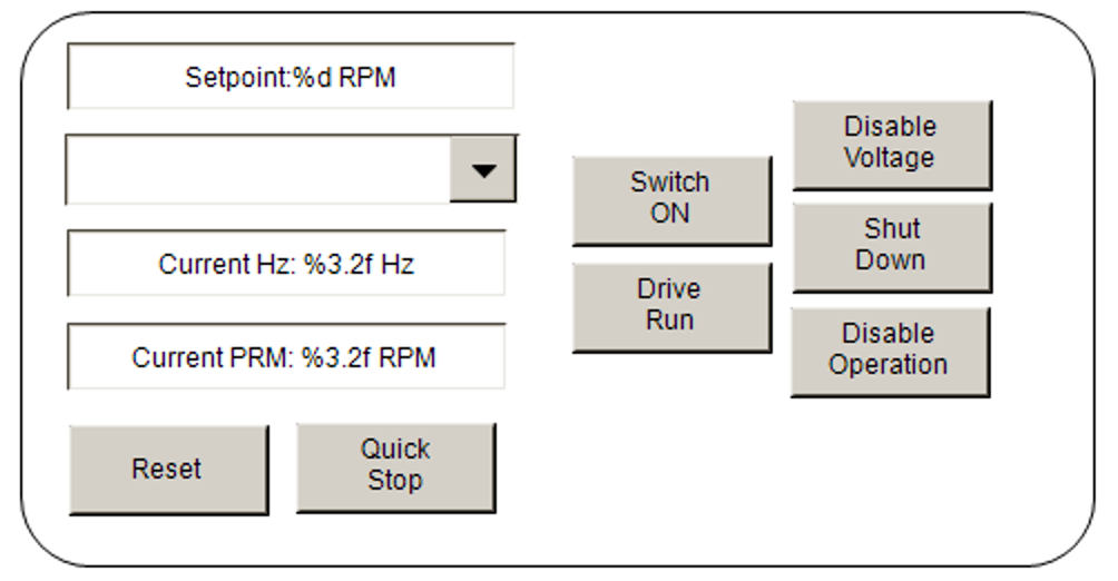
HMI
The next step is to prepare a simple HMI using TF1800.
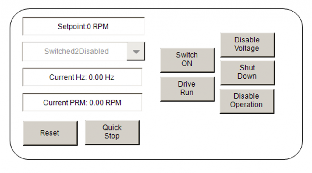
Result
Initially, State=Switched2Disabled, right?
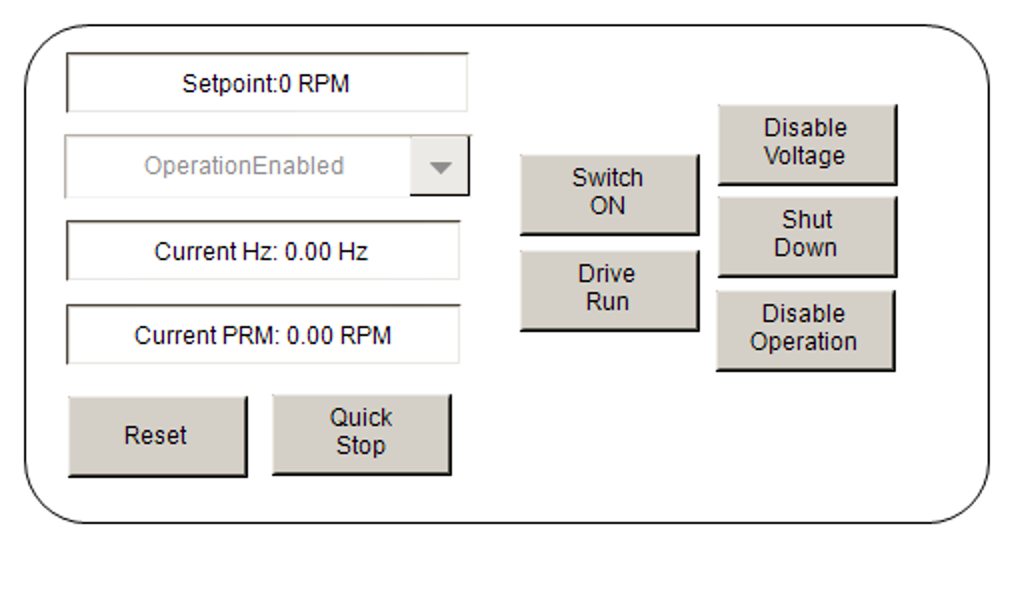
Click on the Switch ON Button to move to State=OperationEnabled.
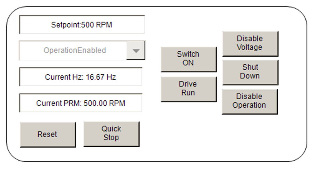
Let’s change Setpoint and issue a speed command value to the ATV320. The current HZ value and current RPM will also be displayed.
Finally, use the Disable Voltage button to shift the ATV320 to Switched2Disabled.

Download
Download the article project from Github.
https://github.com/soup01Threes/TwinCAT3/blob/main/Project_EL6751_ATV320_CANOPEN_Part1.tnzip