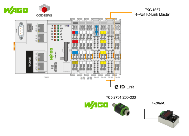
This article uses WAGO’s 750-8215, a new 4 Port IO-Link master, connecting it to WAGO’s analogue 4-20mA output to IOLINK converter, and creating a Codesys program and screen.
Come on, let’s enjoy FA.
Foreword
Thank you from the bottom of my heart for visiting my technical blog and YouTube channel.
We are currently running the “Takahashi Chris” radio show with Full-san (full@桜 八重 (@fulhause) / X) which I deliver every Wednesday night.
Currently, our activities continue almost free of charge, and your warm support is very important for us to provide more content.If you are able, we would be very happy if you could support us by clicking on the links below.
Membership of Takahashi Chris
You can sign up for a membership to the radio we are doing with MR.Full (full@桜 八重 (@fulhause) / X from here.
https://note.com/fulhause/membership/join
AMAZON Gift List
This will be of great use to me in creating content for my blog and improving my facilities.
https://www.amazon.co.jp/hz/wishlist/ls/H7W3RRD7C5QG?ref_=wl_share
Patreon
Here is a small Patreon of support for the creation of content and equipment for my blog.
https://www.patreon.com/user?u=84249391
Your support will help us to enhance our activities.
Thank you in advance for your support.
Email Address(*=@)
X
IO-Link Function?
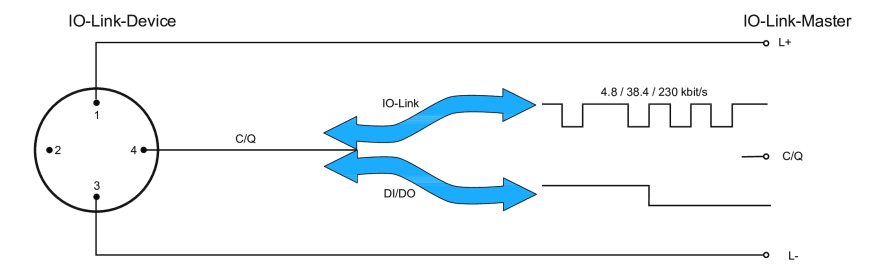
IO-Link defines a communication standard (according to IEC 61131-9) for connecting both general digital inputs/outputs and intelligent IO-Link devices to the control level. IO-Link devices are field-level sensors and actuators with IO-Link functionality.
With IO-Link, process data communication as well as configuration, diagnosis and maintenance can be performed from the controller to the lowest field level. For example, sensor faults can be diagnosed and identified in the controller.
By storing parameter data in the IO-Link master, e.g. in a PLC, and using the pre-configuration option, connected IO-Link devices can be easily replaced or their settings copied. Communication takes place via a serial peer-to-peer link with 3-wire connection technology. Data, diagnostic information and power are transmitted simultaneously via the IO-Link interface.
The configuration of IO-Link devices is based on standardised “IO Device Description” (IODD) files. These are provided by the IO-Link device manufacturer and imported into the specific configuration software.
This allows IO-Link devices to be integrated into common automation systems and network structures.
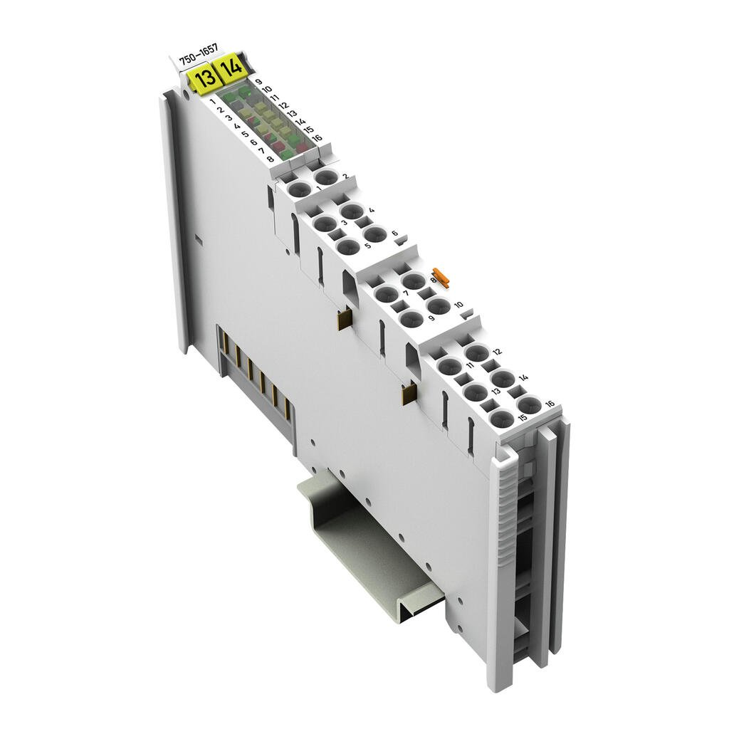
750-1657?
The 750-1657 is a four-port IO-Link master that serves to connect intelligent sensors and actuators used by the IOLink communication system at controller level. Up to four IO-Link devices can be connected to each port of the I/O-Link master thanks to 3-wire connection technology.
You can configure and parameterise the IO-Link master using the function blocks provided by WAGO, the Device Description Profile, WAGO I/O Check or the WAGO IO-Link Configurator The I/O modules are available in Enhanced and Standard two modes of operation are offered.
It should be noted that the enhanced operating mode is currently only available in combination with 3rd generation PROFINET fieldbus couplers with firmware version 12 or higher.
For all other headstations, the 4-port IO-Link master operates in standard operating mode.
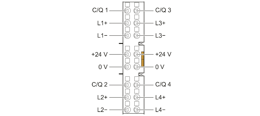
wiring
The 750-1657 4-port IO-Link master helps IOLink communication systems connect intelligent sensors and actuators for use at controller level.3-wire connection technology allows up to four IO-Link devices to be connected to each port on the I/O-Link master The 3-wire connection technology allows up to four IO-Link devices to be connected to each port of the I/O-Link master.
You can also configure and parameterise the IO-Link master using function blocks, device descriptions, WAGO I/O Check or the WAGO IO-Link Configurator.
process data
The process image size of the 750-1657 4-port IO-Link master can be adjusted according to the number of connected devices (e.g. switches, IO-Link devices) and their data volume.
On the local bus side, the 4-port IO-Link master can be set to 4, 6, 8, 10, 12, 16, 20, 24, 32, 40 or 48 bytes. (By default, the process image size is preset to 24 bytes for input and output data, of which 4 bytes are allocated to the acyclic mailbox).
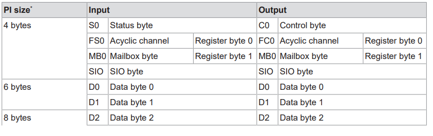
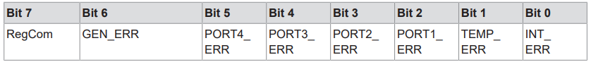
Status Bytes
This is the meaning of the 0th Status Bytes of the 750-1657 4-port IO-Link master.
| Bit位置 | 変数名 | 説明 |
| 7 | RegCom | In Register communication status,1 = Register communication enabled. |
| 6 | GEN_ERR | 0 = No error.1 = with error.It is set if at least one of bits 0-5 is 1. |
| 5 | PORT4_ERR | 0 = Device connected to port 4 is in a normal state1 = Device connected to port 4 is in error state |
| 4 | PORT3_ERR | 0 = Device connected to port 3 is in a normal state1 = Device connected to port 3 is in error state |
| 3 | PORT2_ERR | 0 = Device connected to port 2 is in a normal state1 = Device connected to port 2 is in error state |
| 2 | PORT1_ERR | 0 = Device connected to port 1 is in a normal state1 = Device connected to port 1 is in error state |
| 1 | TEMP_ERR | 0=IO-Link master has a temperature error or overload alarm1=IO-Link master is not alarmed for temperature error or overload |
| 0 | INT_ERR | 0 = No internal error.1 = Internal error present.。 |
Codesysライブラリ‐fbIOL_Call
A library called WagoAppIOLink is available from WAGO to perform various operations with the 750-1657. This article uses fbIOL_Call to read and write parameters of the IO-LINK device.

VAR_INPUT
| variable name | Type | Description |
| I_Port | WagoTypesModule_75x_657.I_Module_75x_657 | Access to modules |
| xExecute | BOOL | Start of IOL call command execution with start-up signal. |
| xWriteRead | BOOL | 0=read1=write |
| bEntity | BYTE | 0 = configuration data from the module.1= device on port 1, 2= device on port 2. |
| iFI_Index | INT | Default=98, access to IO Link sensor. |
| wIOL_Index | WORD | Index of IO link, e.g. 16 = IO link manufacturer name |
| bIOL_Subindex | BYTE | Sub-index of IO links. |
| wLen | WORD | Data length in case of write command |
| tTimeout | TIME |
VAR_IN_OUT
| variable name | Type | Description |
| aIOL_Data | ARRAY [0..255] OF BYTE | IOL data by command |
VAR_OUT
| variable name | Type | Description |
| xDone | BOOL | 1 = Command executed without error. |
| xBusy | BOOL | 1 = Command is being executed. |
| xError | BOOL | 1 = Command executed with error. |
| oStatus | WagoSysErrorBase.FbResult | status information |
| typError | typIOL_PDU_Error | IO-LINK-specific error details. |
| iLenResponse | INT | Number of data received by read command |
765-2701/200-000?
The Analog/IO-Link Converter is an economical and compact device for easy integration of conventional analog sensors and actuators into IO-Link enabled systems such as the WAGO I/O System Field.
This enables reliable, cost-effective and interference-free acquisition and output of analogue signals. Digital communication can be easily introduced (retrofitted) when modernising older systems.
The converter can also be configured directly on the device via IO-Link.Thanks to their compact design, IP67 protection rating and high operating temperature range, Analog/IO-Link converters are ideal for automation without control cabinets.
The 765-2701/200-000 is used to evaluate analogue signals, connected sensors or other devices with analogue outputs. It has x1 analogue current input and x2 outputs.
- Output 1 is a digital output
- Output 2 can optionally be used as an analogue current output.
And it can operate in stand-alone mode and IO-Link mode.
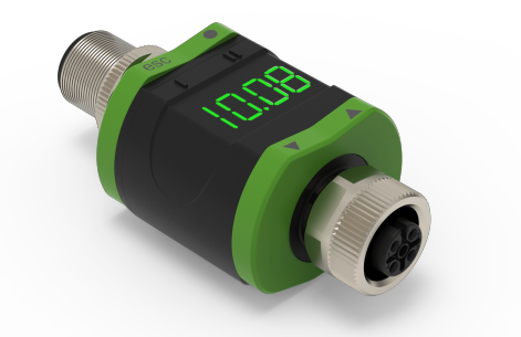
layout
This is Layout 765-2701/200-000.

Standalone mode (without IO-Link)
The 765-2701/200-000 compares the measured current value with the parameter settings and switches the output according to the selected parameters.
The measured value is shown on the alphanumeric display and the user can scale the displayed value (two-point scaling).
Note that there is no IO-Link function in this mode. Parameters are set directly on the 765-2701/200-000 itself or using an IO-Link tool such as the WAGO IO-Link Configurator.
IO-Link mode
IO-Link is a communication system for connecting intelligent sensors and actuators to automation systems IO-Link complies with the IEC 61131-9 standard.
The 765-2701/200-000 has an IO-Link communication interface and requires an IO-Link enabled module (IO-Link master) for interoperation The IO-Link interface allows direct access to process and diagnostic data and allows product parameters to be The IO-Link interface provides direct access to process and diagnostic data and allows product parameters to be set during operation.
parameter
There are many parameters that can be set for the 765-2701/200-000, so this article only describes the parts that are relevant for changing the colour of the display and the setting range of the output.
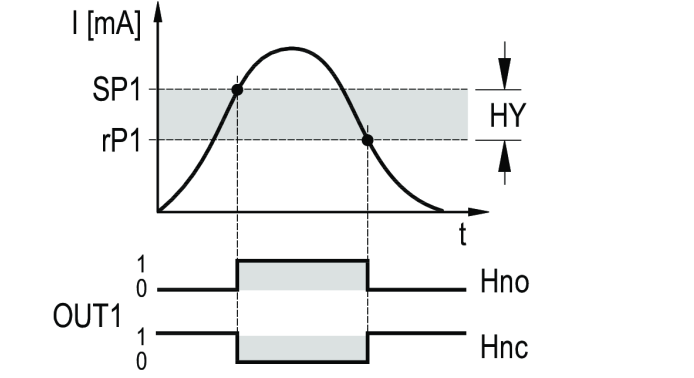
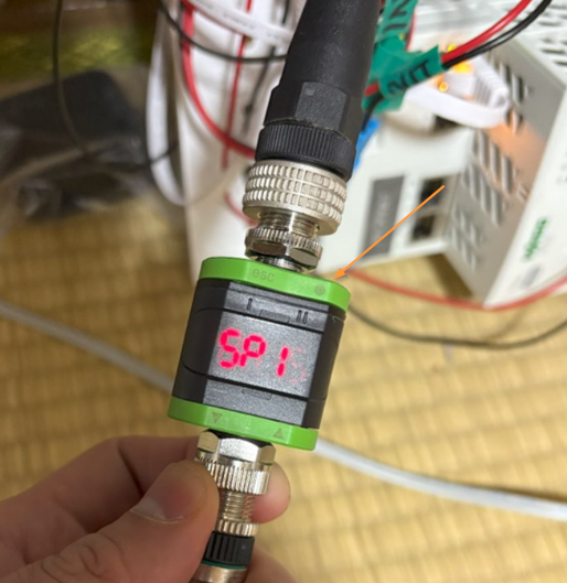
SP1/rP1
This is the OUT1 switching point/reversal switching point.
cFH/cFL
This is the upper/lower limit value for the colour change of the 765-2701/200-000 display LED.If the [coLr] parameter is set to [r-cF] or [G-cF], the [cFH] parameter must be selected to set the corresponding upper limit and the [cFL] parameter to set the corresponding lower limit.
- The lower limit setpoint is parameter [cFL].
- The upper limit setpoint is parameter [cFH].
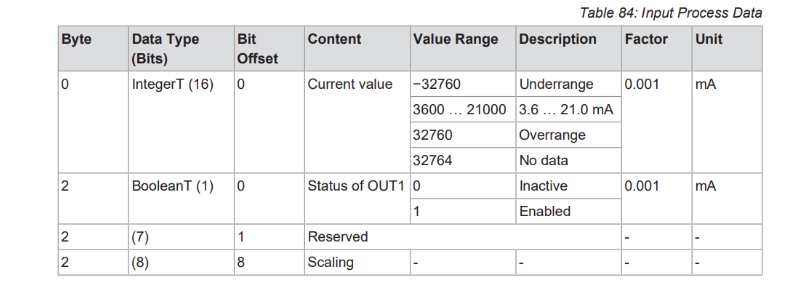
process data
This is the 765-2701/200-000 Mapping. Note that, depending on the controller, the upper and lower bytes may need to be swapped (SWAP) when addressing in byte units.

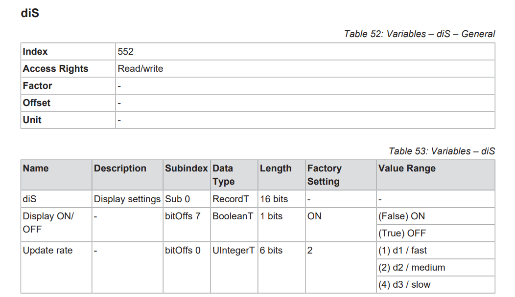
Parameter read/write via IO-Link
When using the 765-2701/200-000 as IO-LINK mode, parameters can be read and written from the higher-level controller. In this example, if you can confirm that you can access the diS parameters with Index=552 and SubIndex=0, you can then just use the IO-LINK library provided by WAGO.
use case
This is an example of use.

Implementation
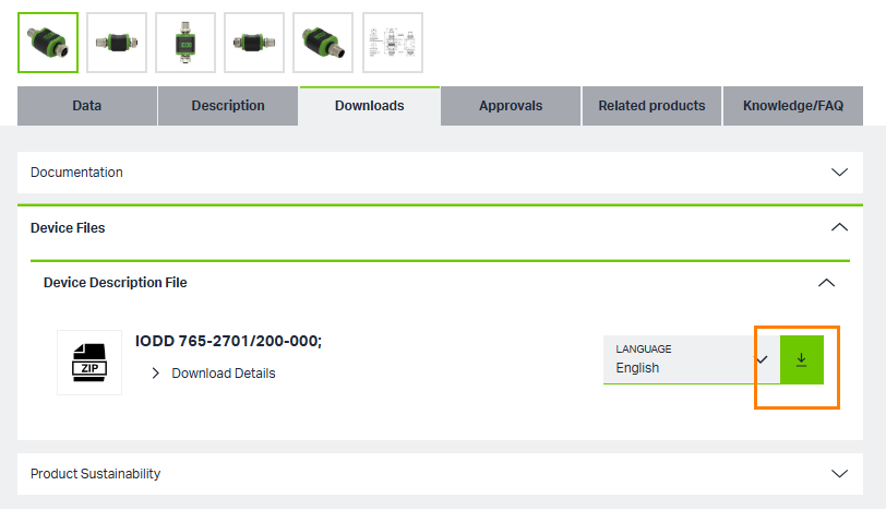
Download IODD File
Download the WAGO 765-2701/200-000 IODD File at this Link.
https://www.wago.com/global/i-o-systems/1-channel-analog-input/p/765-2701_200-000
Factory Reset
First Factory Reset 765-2701/200-000.
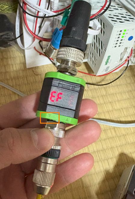
Press the circle button in the top right-hand corner to enter Menu.
Press the Menu selection button in the orange frame to go to the “EF” operating menu.
Next, press the circle button again to enter the “rES ” Menu.
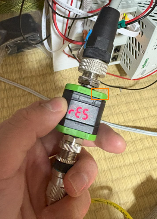
Press the circle button one more time and select rES.
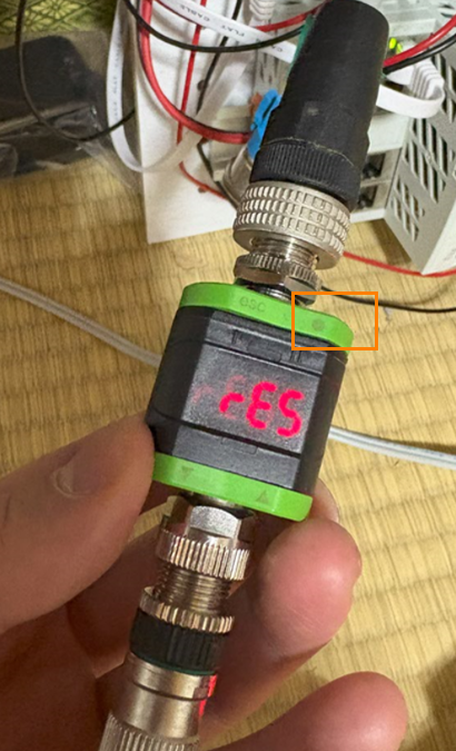
Press the up or down arrow button to perform a Factory Reset.
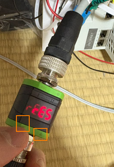
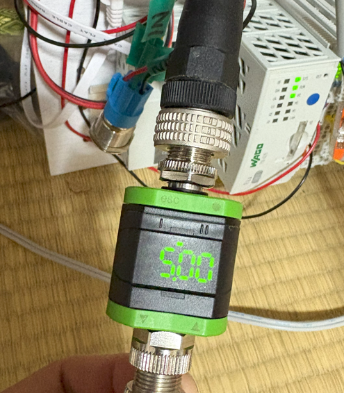
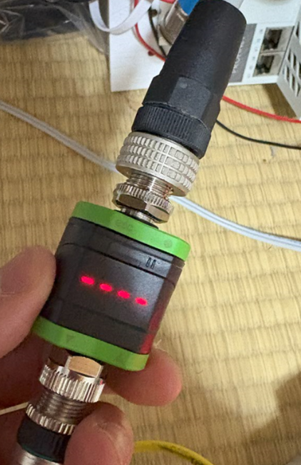
The device display screen changes to “—-“.
Finally, press the circle button again and you are done.

Install WAGO IO Check
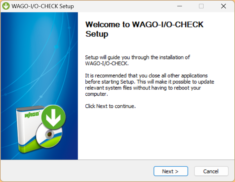
The WAGO I/O Check software must be installed to use the 750-1657. Start its setup FILE and proceed with Next>.
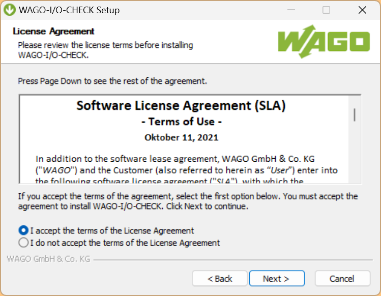
Agree to the licence and proceed with Next.
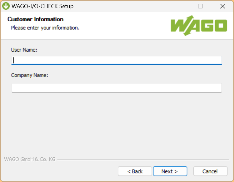
Enter brief personal details and proceed with Next.
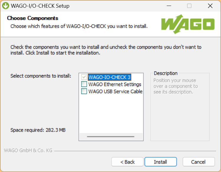
CHECK for the required software and proceed with Install.
Please wait a moment…

Done!WAGO I/O CHECK software could be installed.

Configure IO-Link Master
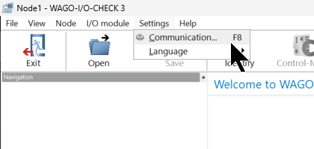
To build the 750-1657, you first need to set up the WAGO CPU connection, click Settings>Communication.
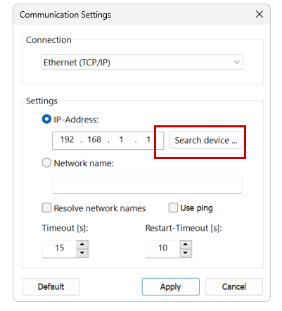
This is the configuration screen for communicating with the WAGO CPU.

Configure how to communicate with the WAGO CPU from the Drop-Down list in Connection. In this article, Ethernet (TCP/IP) is used.

The next step is to set the IP address of the WAGO CPU.
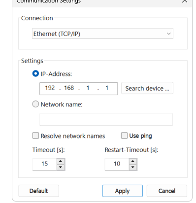
If you do not know the IP address of the WAGO CPU, click Search device and search for WAGO devices in the network.
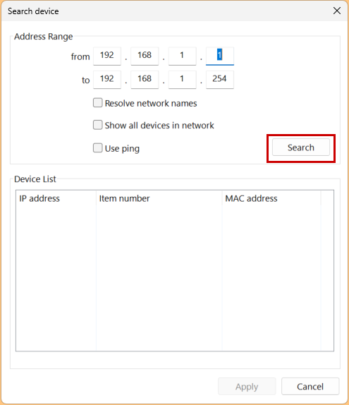
Set the IP address range to search and click Search.
Done!You could search for the WAGO PFC200 used in this article.
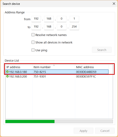
Select that PFC200 and click the Apply button to apply the settings.
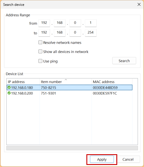
Click Apply one more time to apply the settings.

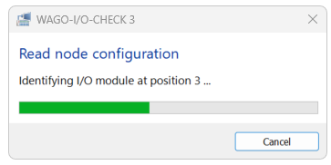
Software tries PFC200 connection …
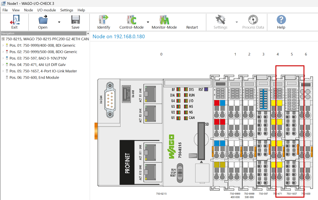
Done!WAGO PFC200の本体だけではなく、右側にインストールされてたIOモジュールの情報も全部吸い上げました。
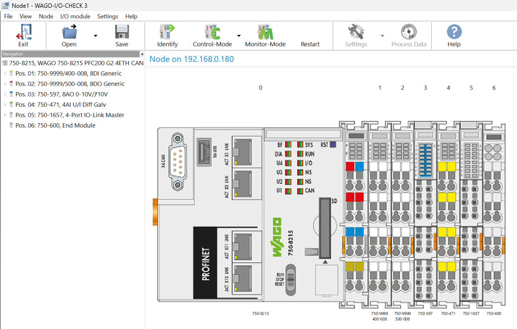
こちらは今回記事で使用する750−1657ですね。
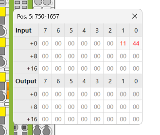
Check Process Data
750−1657を選び>右クリック>Process Dataします。
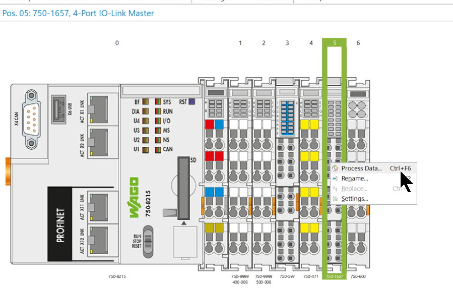
PFC200がRunモードのときはIOモジュールをアクセスすることが拒否されます。
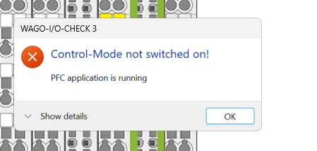
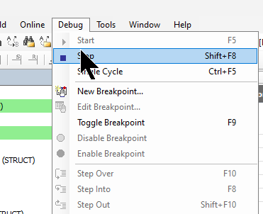
Codesys側で一回Runtimeを止めます。
Done!先程の操作をもう一回行うと、750-1657の生データを確認できました。
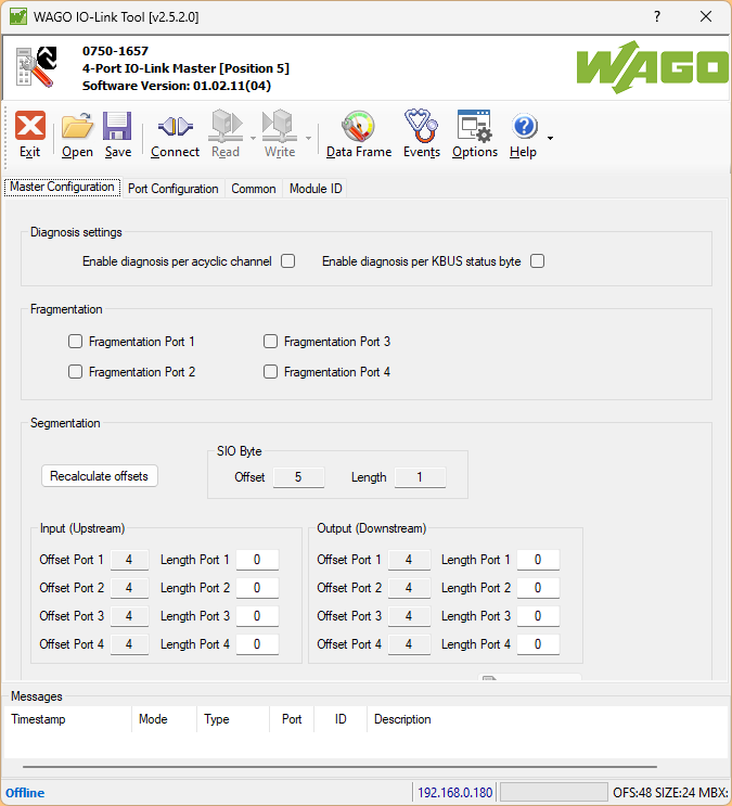
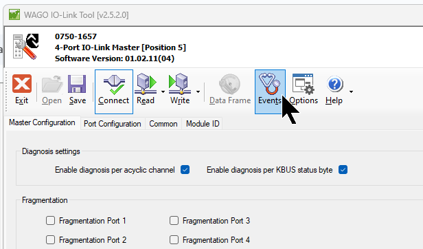
Settings
次は750-1657を右クリック>Settingsを開きます。
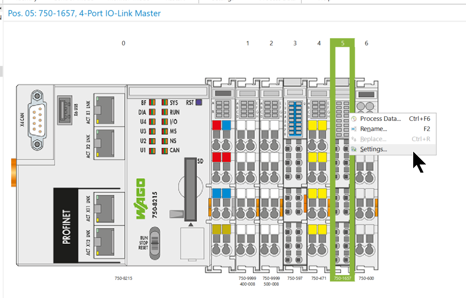
こちらの画面で750-1657のパラメータの確認・変更できます。
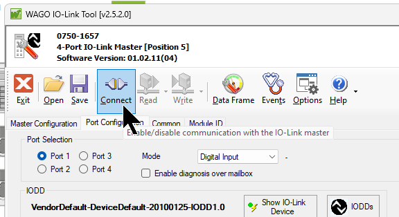
Connect to 750-1657
Click the Connect button to connect the software to the 750-1657.
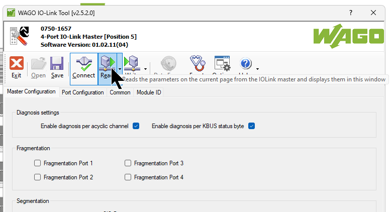
Read Data from 750-1657
Next, click the Read button to read the current module settings.
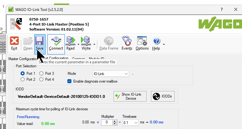
Save Data
Click the Save button to save the current settings.
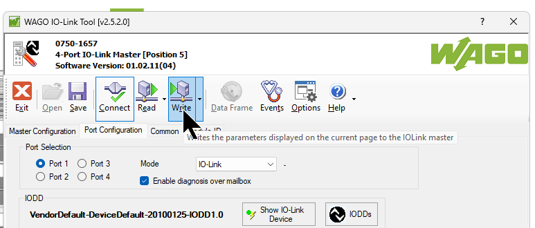
Write Data to 750-1657
It is also possible to write the settings to 750-1657 by clicking the Write button.
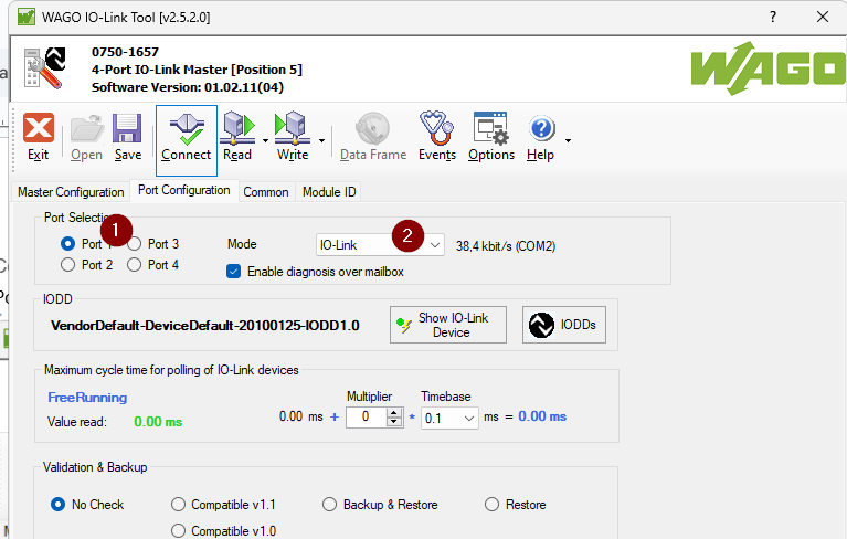
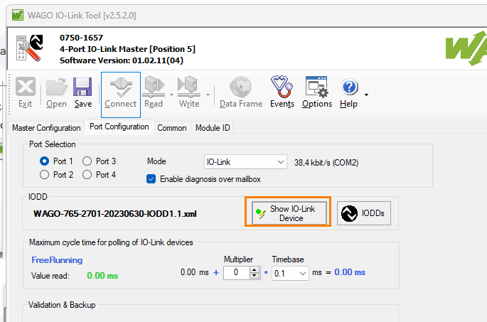
Configure Port1
The next step is to configure 750-1657 Port1.
Mode
Since Port 1 is connected to an IO-LINK device, select Port 1 for Port Selction and set >Mode to IO-Link.
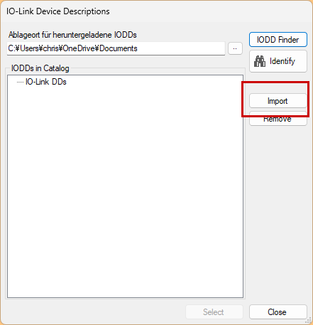
Install IODDs FILEに
Next we will install the IOODs FILE into the tool, click on IODDs.
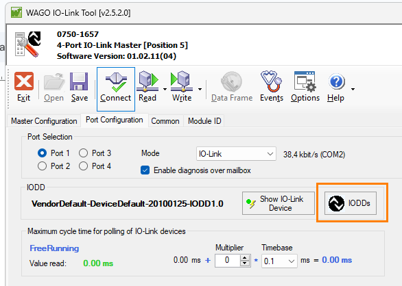
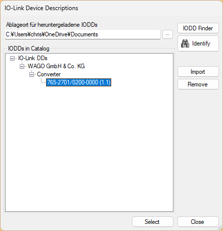
Impot the IODD File downloaded from WAGO HP earlier.

Done!
Get Device Data
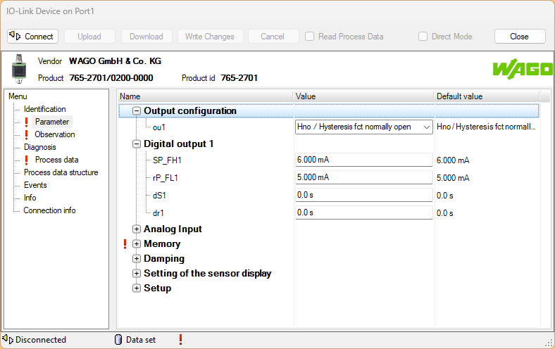
Next, click on “Show IO-Link Device” to see the data and parameters of the IO-Link device.
Click on the Connect button to change parameters, etc.
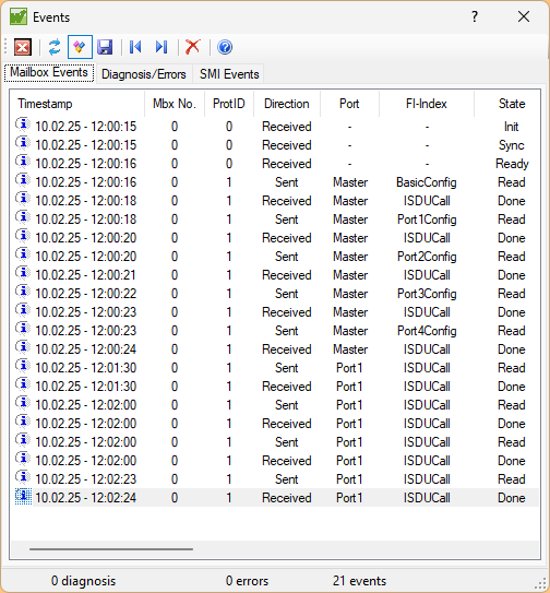
Events
Click on the Events button to view the operating history of the IO-Link master.
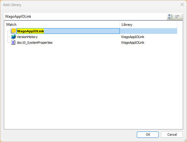
Add Codesys Library
Add the WagoAppIOLink library to your Codesys project.
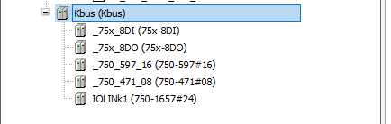
Scan K-Bus
Codesys can also automatically search for WAGO’s K-BUS, so right-click on K-BUS>Scan for Devices.
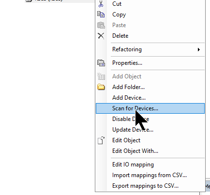
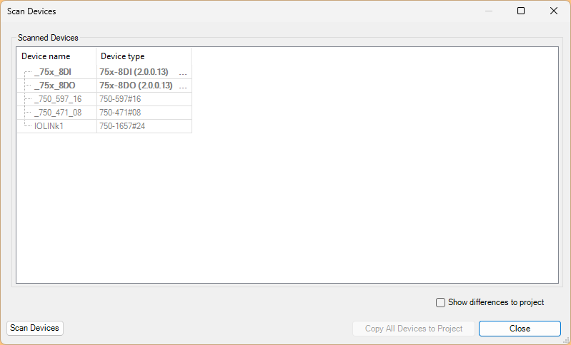
Done!I was able to see all the devices installed on the WAGO PFC200.
DUT
DUT_765_2701_200_000_w
Here is a structure that summarizes the parameters to be written to WAGO’s analog IOLINK converter.
| TYPE DUT_765_2701_200_000_w : STRUCT iSP_FH1:INT; //index583 irP_FL1:INT; //index584 icFL:INT; //index555 icFH:INT; //index556 uicoLr:USINT; //index554 idiS:UINT; //index552 iWrite: int; END_STRUCT END_TYPE |
DUT_765_2701_200_000
This is a structure that summarizes the access parameters to WAGO’s analog IOLINK converter via IO-LINK.
| TYPE DUT_765_2701_200_000 : STRUCT stManufacturer:STRING(19); //index16 stManufacturerText:STRING(30); //index17 stProductName:STRING(18); //index18 stProductID:STRING(10); //index19 stProductText:STRING(30); //index20 stSerialNumber:STRING(12); //index21 stHardwareVersion:STRING(5); //index22 stFirmwareVersion:STRING(5); //index23 iSP_FH1:INT; //index583 irP_FL1:INT; //index584 icFL:INT; //index555 icFH:INT; //index556 uicoLr:USINT; //index554 idiS:UINT; //index552 rCurrentValue :REAL; xOut :BOOL; writeData :DUT_765_2701_200_000_w; END_STRUCT END_TYPE |
Function Block
fb_Wago_750_1657
This FB can get the status of WAGO’s 4-Port IO-Link master.
| FUNCTION_BLOCK fb_Wago_750_1657 VAR_INPUT inModule:WagoAppIOLink.WagoTypesModule_75x_657.I_Module_75x_657; END_VAR VAR_OUTPUT x00_INT_ERR:BOOL; x01_TEMP_ERR:BOOL; x02_PORT1_ERR:BOOL; x03_PORT2_ERR:BOOL; x04_PORT3_ERR:BOOL; x05_PORT4_ERR:BOOL; x06_GEN_ERR:BOOL; x07_REG_COM:BOOL; END_VAR VAR bStatusByte:BYTE; END_VAR |
The program accesses each Bit of data in the 0Byte of 750-1657 to obtain the necessary information.
| bStatusByte:=inModule.GetProcessInByte(0); x00_INT_ERR:=bStatusByte.0; x01_TEMP_ERR:=bStatusByte.1; x02_PORT1_ERR:=bStatusByte.2; x03_PORT2_ERR:=bStatusByte.3; x04_PORT3_ERR:=bStatusByte.4; x05_PORT4_ERR:=bStatusByte.5; x06_GEN_ERR:=bStatusByte.6; x07_REG_COM:=bStatusByte.7; |
fb_Wago_765_2701_200_000
Next we will create a FB for WAGO’s 765-721-200 analog IOLINK converter.
| FUNCTION_BLOCK fb_Wago_765_2701_200_000 VAR_INPUT inModule:WagoAppIOLink.WagoTypesModule_75x_657.I_Module_75x_657; inPort:BYTE:=1; END_VAR VAR_OUTPUT END_VAR VAR_IN_OUT io:DUT_765_2701_200_000; END_VAR VAR arrBytes:ARRAY[0..9]OF BYTE; myWord:INT; fbIOL_CALL_Read:WagoAppIOLink.FbIOL_Call; fbIOL_CALL_Write:WagoAppIOLink.FbIOL_Call; xExecute:BOOL; xWriteRead:BOOL; aIOL_Data:ARRAY[0..255]OF BYTE; istep:INT:=0; bEntity:BYTE:=1; wIOL_Index:WORD; bIOL_Subindex:BYTE; wLen:WORD; aIOL_Data1:ARRAY[0..255]OF BYTE; iCounter:DINT; fbInitTimer:Standard.TON; fbInitStart:Standard.R_TRIG; fbTimer2:Standard.TON; xinited:BOOL; wWriteBufferWord:WORD; END_VAR |
In the program, various data are retrieved via IO-Link.Information such as manufacturer name is basically constant, so it is only necessary to read it in the first time.After that, the necessary parameters are read in via Looping, and the data can be parameterized again from the HMI.
| //Read Operation CASE istep OF 0: //Init fbInitTimer(IN:=TRUE,PT:=T#1S); iCounter:=0; xExecute:=FALSE; xinited:=FALSE; IF NOT fbIOL_CALL_Read.xBusy AND NOT fbIOL_CALL_Read.xError AND fbInitTimer.Q THEN istep:=10; fbInitTimer(IN:=FALSE); END_IF; 10: //stManufacturer xExecute:=TRUE; wIOL_Index:=16; bIOL_Subindex:=0; wLen:=19; IF fbIOL_CALL_Read.xDone THEN istep:=15; END_IF 15: IF fbIOL_CALL_Read.xDone THEN xExecute:=FALSE; WagoSysPlainMem.MemCopy( pDest:=ADR(io.stManufacturer) ,pSource:=ADR(aIOL_Data) ,udiSize:=TO_UDINT(fbIOL_CALL_Read.iLenResponse) ); istep:=20; END_IF 20://stManufacturerText xExecute:=TRUE; wIOL_Index:=17; bIOL_Subindex:=0; wLen:=11; IF fbIOL_CALL_Read.xDone THEN istep:=25; END_IF 25: IF fbIOL_CALL_Read.xDone THEN xExecute:=FALSE; WagoSysPlainMem.MemCopy( pDest:=ADR(io.stManufacturerText) ,pSource:=ADR(aIOL_Data) ,udiSize:=TO_UDINT(fbIOL_CALL_Read.iLenResponse) ); istep:=30; END_IF 30://stProductName xExecute:=TRUE; wIOL_Index:=18; bIOL_Subindex:=0; wLen:=6; IF fbIOL_CALL_Read.xDone THEN istep:=35; END_IF 35: IF fbIOL_CALL_Read.xDone THEN xExecute:=FALSE; WagoSysPlainMem.MemCopy( pDest:=ADR(io.stProductName) ,pSource:=ADR(aIOL_Data) ,udiSize:=TO_UDINT(fbIOL_CALL_Read.iLenResponse) ); istep:=40; END_IF 40://stManufacturerText xExecute:=TRUE; wIOL_Index:=20; bIOL_Subindex:=0; wLen:=30; IF fbIOL_CALL_Read.xDone THEN istep:=45; END_IF 45: IF fbIOL_CALL_Read.xDone THEN xExecute:=FALSE; WagoSysPlainMem.MemCopy( pDest:=ADR(io.stManufacturerText) ,pSource:=ADR(aIOL_Data) ,udiSize:=TO_UDINT(fbIOL_CALL_Read.iLenResponse) ); istep:=50; END_IF; 50://stProductID xExecute:=TRUE; wIOL_Index:=19; bIOL_Subindex:=0; wLen:=6; IF fbIOL_CALL_Read.xDone THEN istep:=55; END_IF 55: IF fbIOL_CALL_Read.xDone THEN xExecute:=FALSE; WagoSysPlainMem.MemCopy( pDest:=ADR(io.stProductID) ,pSource:=ADR(aIOL_Data) ,udiSize:=TO_UDINT(fbIOL_CALL_Read.iLenResponse) ); istep:=60; END_IF 60://stProductText xExecute:=TRUE; wIOL_Index:=20; bIOL_Subindex:=0; wLen:=30; IF fbIOL_CALL_Read.xDone THEN istep:=65; END_IF 65: IF fbIOL_CALL_Read.xDone THEN xExecute:=FALSE; WagoSysPlainMem.MemCopy( pDest:=ADR(io.stProductText) ,pSource:=ADR(aIOL_Data) ,udiSize:=TO_UDINT(fbIOL_CALL_Read.iLenResponse) ); istep:=70; END_IF 70://stSerialNumber xExecute:=TRUE; wIOL_Index:=21; bIOL_Subindex:=0; wLen:=12; IF fbIOL_CALL_Read.xDone THEN istep:=75; END_IF 75: IF fbIOL_CALL_Read.xDone THEN xExecute:=FALSE; WagoSysPlainMem.MemCopy( pDest:=ADR(io.stSerialNumber) ,pSource:=ADR(aIOL_Data) ,udiSize:=TO_UDINT(fbIOL_CALL_Read.iLenResponse) ); istep:=80; END_IF 80://stHardwareVersion xExecute:=TRUE; wIOL_Index:=22; bIOL_Subindex:=0; wLen:=2; IF fbIOL_CALL_Read.xDone THEN istep:=85; END_IF 85: IF fbIOL_CALL_Read.xDone THEN xExecute:=FALSE; WagoSysPlainMem.MemCopy( pDest:=ADR(io.stHardwareVersion) ,pSource:=ADR(aIOL_Data) ,udiSize:=TO_UDINT(fbIOL_CALL_Read.iLenResponse) ); istep:=90; END_IF 90://stFirmwareVersion xExecute:=TRUE; wIOL_Index:=23; bIOL_Subindex:=0; wLen:=2; IF fbIOL_CALL_Read.xDone THEN istep:=95; END_IF 95: IF fbIOL_CALL_Read.xDone THEN xExecute:=FALSE; WagoSysPlainMem.MemCopy( pDest:=ADR(io.stFirmwareVersion) ,pSource:=ADR(aIOL_Data) ,udiSize:=TO_UDINT(fbIOL_CALL_Read.iLenResponse) ); istep:=100; END_IF 100://iSP_FH1 xExecute:=TRUE; wIOL_Index:=583; bIOL_Subindex:=0; wLen:=SIZEOF(io.iSP_FH1); IF fbIOL_CALL_Read.xDone THEN istep:=105; END_IF 105: IF fbIOL_CALL_Read.xDone THEN xExecute:=FALSE; WagoSysPlainMem.MemCopy( pDest:=ADR(io.iSP_FH1) ,pSource:=ADR(aIOL_Data) ,udiSize:=TO_UDINT(fbIOL_CALL_Read.iLenResponse) ); WagoSysPlainMem.MemSwap(pData:=ADR(io.iSP_FH1),udiSize:=2); istep:=110; END_IF 110://irP_FL1 xExecute:=TRUE; wIOL_Index:=584; bIOL_Subindex:=0; wLen:=SIZEOF(io.irP_FL1); IF fbIOL_CALL_Read.xDone THEN istep:=115; END_IF 115: IF fbIOL_CALL_Read.xDone THEN xExecute:=FALSE; WagoSysPlainMem.MemCopy( pDest:=ADR(io.irP_FL1) ,pSource:=ADR(aIOL_Data) ,udiSize:=TO_UDINT(fbIOL_CALL_Read.iLenResponse) ); WagoSysPlainMem.MemSwap(pData:=ADR(io.irP_FL1),udiSize:=2); istep:=120; END_IF 120://icFL xExecute:=TRUE; wIOL_Index:=555; bIOL_Subindex:=0; wLen:=SIZEOF(io.icFL); IF fbIOL_CALL_Read.xDone THEN istep:=125; END_IF 125: IF fbIOL_CALL_Read.xDone THEN xExecute:=FALSE; WagoSysPlainMem.MemCopy( pDest:=ADR(io.icFL) ,pSource:=ADR(aIOL_Data) ,udiSize:=TO_UDINT(fbIOL_CALL_Read.iLenResponse) ); WagoSysPlainMem.MemSwap(pData:=ADR(io.icFL),udiSize:=2); istep:=130; END_IF 130://icFH xExecute:=TRUE; wIOL_Index:=556; bIOL_Subindex:=0; wLen:=SIZEOF(io.icFH); IF fbIOL_CALL_Read.xDone THEN istep:=135; END_IF 135: IF fbIOL_CALL_Read.xDone THEN xExecute:=FALSE; WagoSysPlainMem.MemCopy( pDest:=ADR(io.icFH) ,pSource:=ADR(aIOL_Data) ,udiSize:=TO_UDINT(fbIOL_CALL_Read.iLenResponse) ); WagoSysPlainMem.MemSwap(pData:=ADR(io.icFH),udiSize:=2); istep:=140; END_IF 140://uicoLr xExecute:=TRUE; wIOL_Index:=554; bIOL_Subindex:=0; wLen:=SIZEOF(io.uicoLr); IF fbIOL_CALL_Read.xDone THEN istep:=145; END_IF 145: IF fbIOL_CALL_Read.xDone THEN xExecute:=FALSE; WagoSysPlainMem.MemCopy( pDest:=ADR(io.uicoLr) ,pSource:=ADR(aIOL_Data) ,udiSize:=TO_UDINT(fbIOL_CALL_Read.iLenResponse) ); WagoSysPlainMem.MemSwap(pData:=ADR(io.uicoLr),udiSize:=1); istep:=150; END_IF 150://idiS xExecute:=TRUE; wIOL_Index:=552; bIOL_Subindex:=0; wLen:=SIZEOF(io.idiS); IF fbIOL_CALL_Read.xDone THEN istep:=155; END_IF 155: IF fbIOL_CALL_Read.xDone THEN xExecute:=FALSE; WagoSysPlainMem.MemCopy( pDest:=ADR(io.idiS) ,pSource:=ADR(aIOL_Data) ,udiSize:=TO_UDINT(fbIOL_CALL_Read.iLenResponse) ); WagoSysPlainMem.MemSwap(pData:=ADR(io.idiS),udiSize:=2); istep:=100; xinited:=TRUE; END_IF END_CASE //Reset while Error IF fbIOL_CALL_Read.xError THEN istep:=0; END_IF //Read the current arrBytes[1]:=inModule.GetProcessInByte(ByteNo:=6); arrBytes[0]:=inModule.GetProcessInByte(ByteNo:=7); MEMUtils.MemCpy( ADR(myWord), ADR(arrBytes[0]) ,2 ); io.rCurrentValue:=TO_REAL(myWord)/1000.0; //Read the ou1 Status arrBytes[0]:=inModule.GetProcessInByte(ByteNo:=9); io.xOut:=arrBytes[0].0; //init fbTimer2(IN:=xinited,PT:=T#0.1S); fbInitStart( CLK:=xinited AND fbTimer2.Q ); IF fbInitStart.Q THEN io.writeData.icFH:=io.icFH; io.writeData.icFL:=io.icFL; io.writeData.idiS:=io.idiS; io.writeData.irP_FL1:=io.irP_FL1; io.writeData.iSP_FH1:=io.iSP_FH1; io.writeData.uicoLr:=io.uicoLr; END_IF //Read FB fbIOL_CALL_Read( I_Port:=inModule ,xExecute:=xExecute ,xWriteRead:=xWriteRead ,bEntity:=inPort ,iFI_Index:=98 ,wIOL_Index:=wIOL_Index ,bIOL_Subindex:=bIOL_Subindex ,wLen:=wLen ,aIOL_Data:=aIOL_Data ); //Write operation CASE io.writeData.iWrite OF 1: fbIOL_CALL_Write.wIOL_Index:=556; fbIOL_CALL_Write.bIOL_Subindex:=0; fbIOL_CALL_Write.wLen:=2; WagoSysPlainMem.MemCopy( ADR(wWriteBufferWord) ,ADR(io.writeData.icFH) ,2); WagoSysPlainMem.MemSwap( ADR(wWriteBufferWord) ,udiSize:=2 ); WagoSysPlainMem.MemCopy( ADR(aIOL_Data1) ,ADR(wWriteBufferWord) ,2); 2: fbIOL_CALL_Write.wIOL_Index:=555; fbIOL_CALL_Write.bIOL_Subindex:=0; fbIOL_CALL_Write.wLen:=2; WagoSysPlainMem.MemCopy( ADR(wWriteBufferWord) ,ADR(io.writeData.icFL) ,2); WagoSysPlainMem.MemSwap( ADR(wWriteBufferWord) ,udiSize:=2 ); WagoSysPlainMem.MemCopy( ADR(aIOL_Data1) ,ADR(wWriteBufferWord) ,2); 3: fbIOL_CALL_Write.wIOL_Index:=552; fbIOL_CALL_Write.bIOL_Subindex:=0; fbIOL_CALL_Write.wLen:=2; WagoSysPlainMem.MemCopy( ADR(wWriteBufferWord) ,ADR(io.writeData.idiS) ,2); WagoSysPlainMem.MemSwap( ADR(wWriteBufferWord) ,udiSize:=2 ); WagoSysPlainMem.MemCopy( ADR(aIOL_Data1) ,ADR(wWriteBufferWord) ,2); 4: fbIOL_CALL_Write.wIOL_Index:=584; fbIOL_CALL_Write.bIOL_Subindex:=0; fbIOL_CALL_Write.wLen:=2; WagoSysPlainMem.MemCopy( ADR(wWriteBufferWord) ,ADR(io.writeData.irP_FL1) ,2); WagoSysPlainMem.MemSwap( ADR(wWriteBufferWord) ,udiSize:=2 ); WagoSysPlainMem.MemCopy( ADR(aIOL_Data1) ,ADR(wWriteBufferWord) ,2); 5: fbIOL_CALL_Write.wIOL_Index:=583; fbIOL_CALL_Write.bIOL_Subindex:=0; fbIOL_CALL_Write.wLen:=2; WagoSysPlainMem.MemCopy( ADR(wWriteBufferWord) ,ADR(io.writeData.iSP_FH1) ,2); WagoSysPlainMem.MemSwap( ADR(wWriteBufferWord) ,udiSize:=2 ); WagoSysPlainMem.MemCopy( ADR(aIOL_Data1) ,ADR(wWriteBufferWord) ,2); 6: fbIOL_CALL_Write.wIOL_Index:=554; fbIOL_CALL_Write.bIOL_Subindex:=0; fbIOL_CALL_Write.wLen:=1; WagoSysPlainMem.MemCopy( ADR(wWriteBufferWord) ,ADR(io.writeData.uicoLr) ,2); WagoSysPlainMem.MemSwap( ADR(wWriteBufferWord) ,udiSize:=1 ); WagoSysPlainMem.MemCopy( ADR(aIOL_Data1) ,ADR(wWriteBufferWord) ,2); END_CASE // IF io.writeData.iWrite >0 THEN fbIOL_CALL_Write.xExecute:=TRUE; IF fbIOL_CALL_Write.xDone OR fbIOL_CALL_Write.xError THEN io.writeData.iWrite:=0; fbIOL_CALL_Write.xExecute:=FALSE; END_IF END_IF; //Write FB fbIOL_CALL_Write( I_Port:=inModule ,bEntity:=inPort ,xWriteRead:=TRUE ,aIOL_Data:=aIOL_Data1 ); |
GVL
Declare a Global variable to store the data of WAGO’s analog to IOLINK converter.
| {attribute ‘qualified_only’} VAR_GLOBAL Devices1:DUT_765_2701_200_000; END_VAR |
MAIN
Declare and call the FB Instance you just created in the MAIN program.
| PROGRAM PLC_PRG VAR FB1:fb_Wago_765_2701_200_000; _750_1657:fb_Wago_750_1657; END_VAR |
| _750_1657(inModule:=IoConfig_Globals.IOLINk1); FB1( inModule:=IoConfig_Globals.IOLINk1 ,inPort:=1 ,io:=GVL.Devices1 ); |
Visualization
Next, let’s create a Codesys HMI screen.
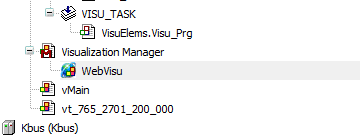
Add WebVisu
Add Visualization Manager and WebVisu to the Codesys project.
Enable Webvisu
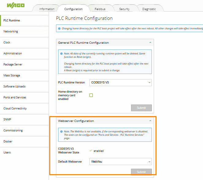
Go to the WAGO PFC200 Web Server and enable the Options shown below under Ports and Services>PLC Runtime Services.
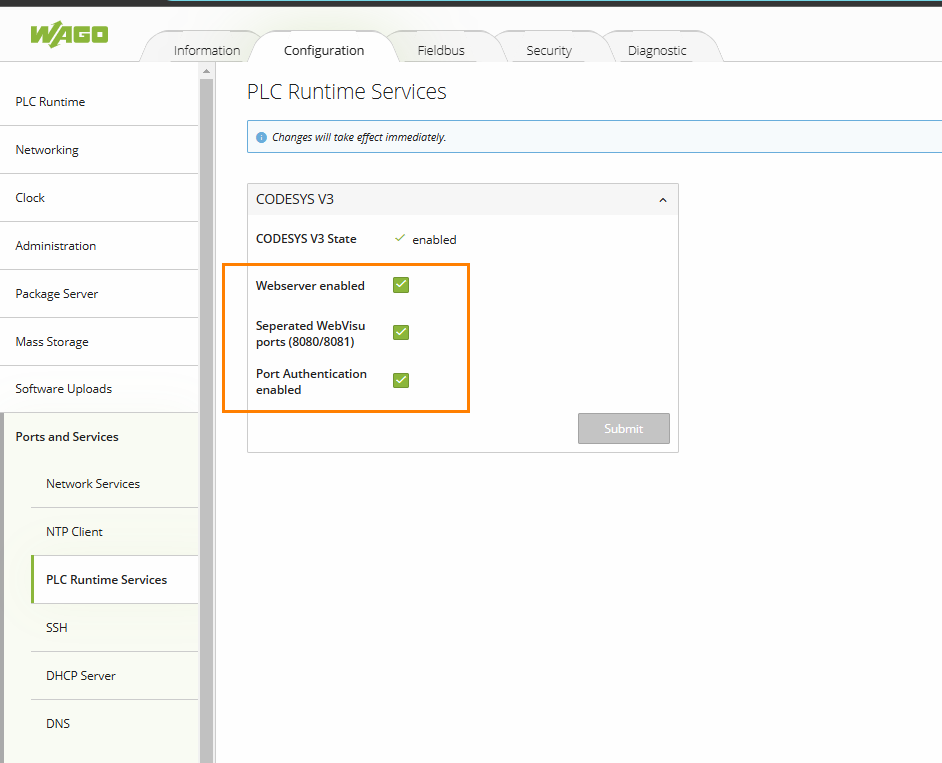
Next, set Configuration>PLC Runtime>Webserver Configuration>Default to “WebVisu”.
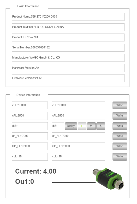
vt_765_2701_200_000
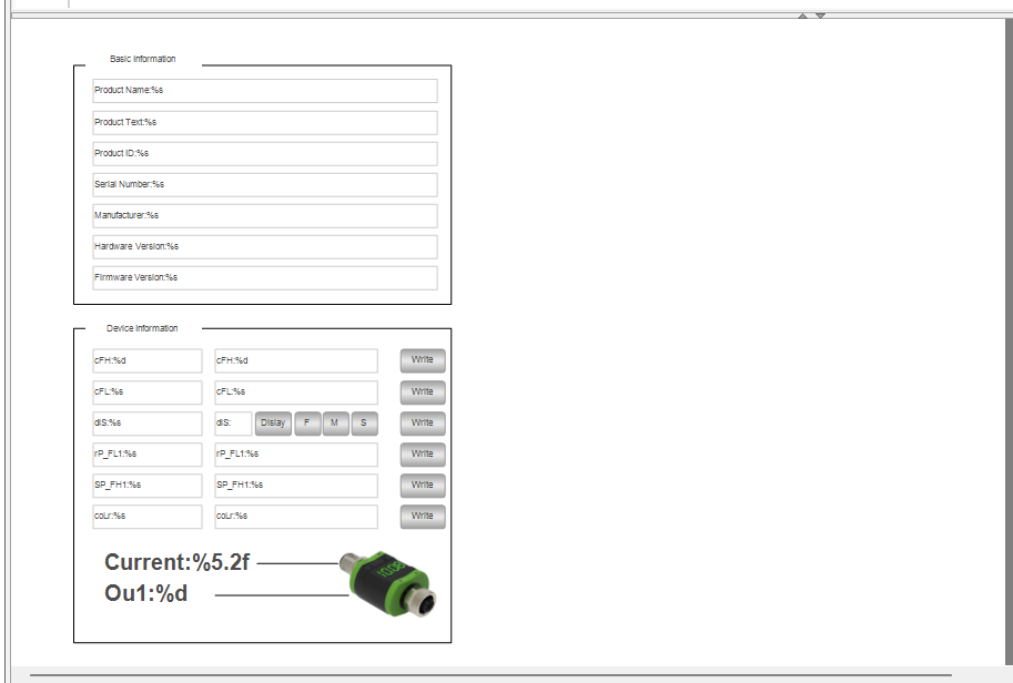
This is the operating Template for 765-2701/200-000.
| VAR_IN_OUT io:DUT_765_2701_200_000; END_VAR |
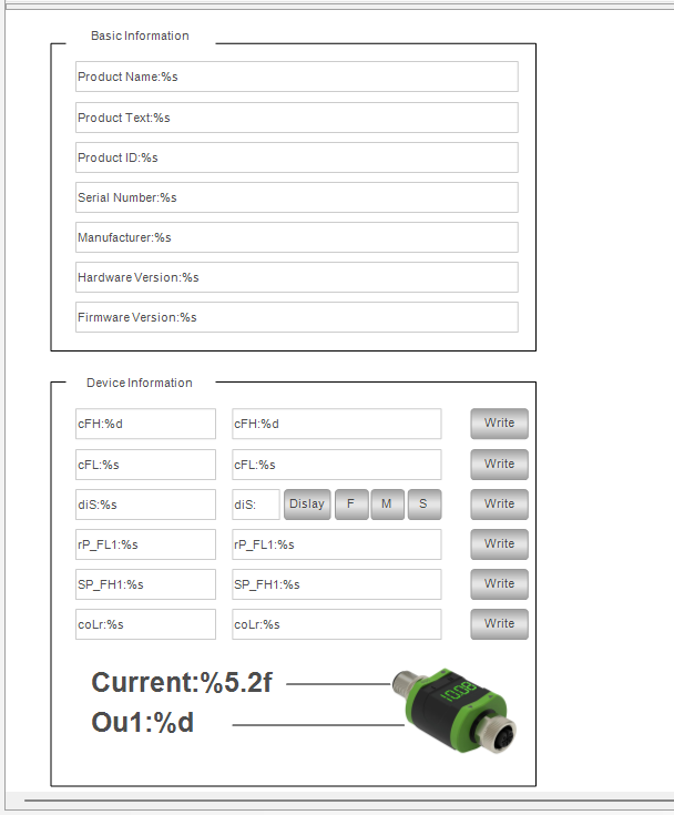
vMain
Next, let’s add the Tempate we declared earlier to the Default page of WebVisu and connect its parameters to the variables we declared in GVL.
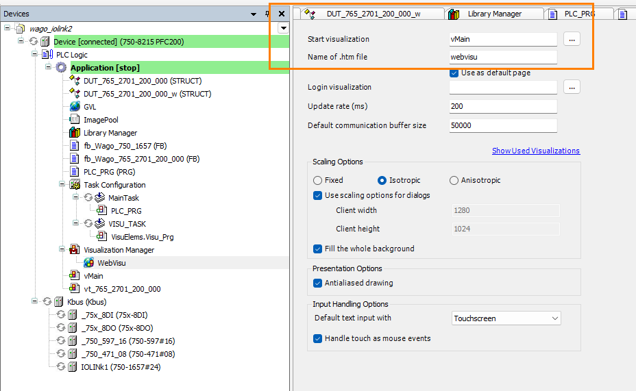
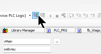
Set Default Page
Let’s set up the Default startup screen at Visualization>WebVisu>Start Visualization.
Login
Download the program to PFC200.
Result
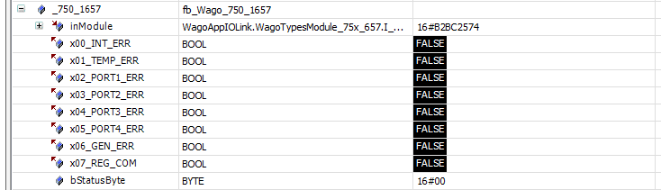
This is the Status Word when the connection between the IO-Link master and the IO-Link device is normal.
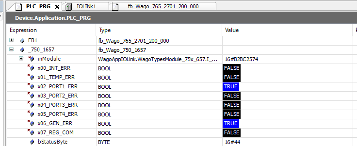
This is the Status Word when a communication error occurs between the IO-Link Master Port 1 and the IO-Link device.
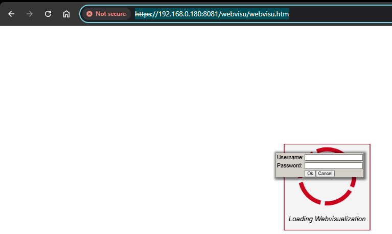
Next, access Codesys WebVisu in PFC 200.
https://IPADDRESS:8081/webvisu/webvisu.htm
Please enter your Username and Password to login.
Done!
You can check the operation from this video.
Wago.playing with 750-1657,Analog/IO-Link Converter and Codesys
Project Download
You can download the project created in this article at this Link.
https://github.com/soup01Threes/Codesys/blob/main/Project_Wago_750-8215.projectarchive