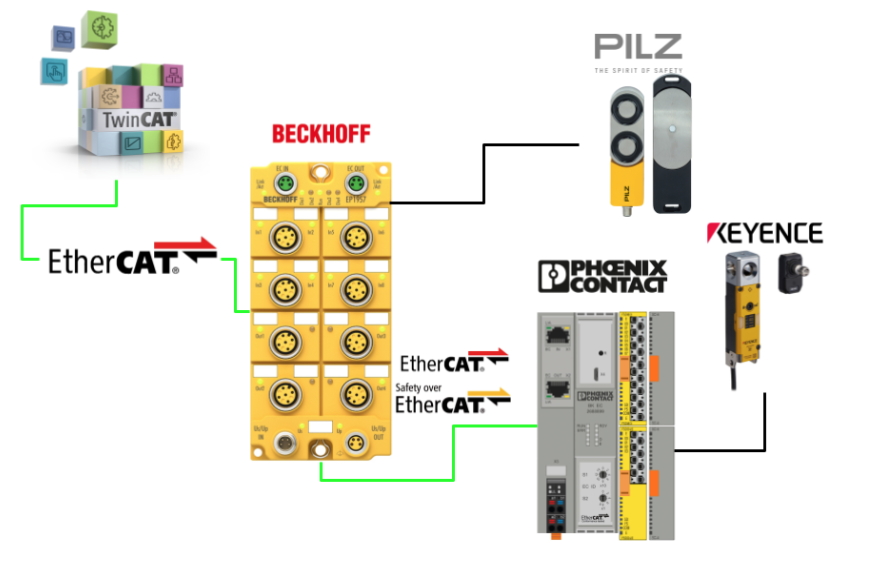
In this article, Beckhoff’s EP1957-0022 is used to set up the EtherCAT and FSoE network and simultaneously connect it to Phoenix Contact’s AXL F BK EC EtherCATCoupler and safety input/output modules. Door locks are used not only from Pilz but also from Keyence GS Lock.
Come on, let’s enjoy FA.
Reference Link
Foreword
Thank you from the bottom of my heart for visiting my technical blog and YouTube channel.
We are currently running the “Takahashi Chris” radio show with Full-san (full@桜 八重 (@fulhause) / X) which I deliver every Wednesday night.
Currently, our activities continue almost free of charge, and your warm support is very important for us to provide more content.If you are able, we would be very happy if you could support us by clicking on the links below.
Membership of Takahashi Chris
You can sign up for a membership to the radio we are doing with MR.Full (full@桜 八重 (@fulhause) / X from here.
https://note.com/fulhause/membership/join
AMAZON Gift List
This will be of great use to me in creating content for my blog and improving my facilities.
https://www.amazon.co.jp/hz/wishlist/ls/H7W3RRD7C5QG?ref_=wl_share
Patreon
Here is a small Patreon of support for the creation of content and equipment for my blog.
https://www.patreon.com/user?u=84249391
Your support will help us to enhance our activities.
Thank you in advance for your support.
Email Address(*=@)
X
AXL F BK EC – Bus coupler?
The AXL F BK EC bus coupler can be used within an EtherCAT® network and is a linkable device to the Axioline F I/O system. Up to 63 Axioline F devices can then be connected to the bus coupler.

Features
The AXL F BK EC – Bus coupler has the following features
- 2 Ethernet ports (built-in switch)
- Rotary encoding switch
- Automatic addressing
- Stations mapped as modular EtherCAT® devices
- Stations can be mapped as block devices
- Acyclic data communication (mailbox protocols)
- Cyclic data communication
- Typical cycle time of the Axioline F local bus is approx. 10 µs
- Bus coupler runtime is negligible (almost 0 µs)
- IOL-CONF supported (from firmware version 1.30 onwards)
- Supports smart elements for use in FSoE systems
(from firmware version 1.31 onwards)
Internal circuit diagram
This is a Block diagram of the AXL F BK EC – Bus coupler.

Connection Example
This is an example of the AXL F BK EC – Bus coupler connection.

Rotary encoding switch
The rotary code switch can be used to assign a Device Identification Value.
The bus coupler must be restarted each time the switch position is changed. Note that changing the switch position during operation has no effect.
This switch can be used to set the Device Identification Value from 1-159.

Synchronizing the application in EtherCAT
With EtherCAT, there are two modes of application synchronisation, which can be selected by the engineering system.
- SM Synchronous
- DC Synchronous
SM Synchronous
In this mode, the EtherCAT® communication system and the local bus operate asynchronously. The local bus is in autorun mode and operates with the minimum cycle time possible with the current module configuration.
DC Synchronous
In this mode, the bus cycles of the local bus are synchronised to EtherCAT® cycles,
The processes are time synchronised using the implemented distributed clock units.
Note that if DC Synchronous is set and there is no module in the Axioline F station that supports local bus synchronisation, the bus coupler will reject the change of state from PREOP to SAFE- with ‘AL status code’ 0028hex (SyncMode not supported). OP and rejects the change of state from PREOP to SAFE- OP.
So, if you use the DC synchronisation mode of the bus coupler, make sure that there is at least one module in the Axioline F station that supports local bus synchronisation.
AXL SE FSDI8/3 ?
The AXL SE FSDI8/3 smart element is a safety input module of the Axioline SE product family for use in FSoE systems (Failsafe over EtherCAT®). The smart element is suitable for use with Axioline F backplanes and the smart element is integrated into the Axioline F system via the backplane.
The smart element has four safe digital inputs for two-channel assignment or eight safe digital inputs for one-channel assignment, and the inputs can be parameterised according to the application. This allows the sensor to be integrated into the safety system.
The smart elements are configured in the FSoE system using the engineering tool corresponding to the safety controller used (TwinSAFE in this article).

Supply voltage
The smart element requires the following supply voltages:
- Communication power supply USE of smart elements
- I/O power supply voltage
Safe digital inputs
The smart element can use secure digital inputs as follows.
- For 2-channel assignment: four 2-channel inputs
- For 1-channel assignment: eight 1-channel inputs

Processing time of the input in the event of a safety demand
The processing time of the input tIN during a safety request consists of a parameterised filter time tFilter and a firmware processing time tFW.

- tIN=Processing time of the input
- tFilter=parameterised filter time.
- tFW=firmware processing time: 7.5 ms
Response time of the FSoE system
When determining the response time of the FSoE system, the controller manufacturer’s specifications must be adhered to (Beckhoff in this article).
Single-channel assignment
In the case of a single-channel assignment of safe inputs, the inputs operate independently of each other; the associated clock output or external power supply (external +24 V or OSSD) can be used to power the single-channel assignment.

State evaluation
The smart element evaluates the state of the input and transmits the result to the controller. In the process data of the safe input, the following values are transmitted:
- 0″ if a “0” signal is present on the input or an error is detected.
- 1″ if a “1” signal is present on the input and no errors are detected.
Two-channel equivalent assignment
In two-channel operation of the input, the channels are assigned as follows:
- IN0_CH1 to IN0_CH2
- IN1_CH1 to IN1_CH2
- IN2_CH1 to IN2_CH2
- IN3_CH1 to IN3_CH2

State evaluation
The smart element evaluates the state of the input and transmits the result to the controller. In the process data of the safe input, the following values are transmitted:
- ‘0’ if a ‘0’ signal is present on at least one of the two inputs or if an error is detected.
- 1″ if there is a “1” signal on both inputs, no errors are detected and the following status change conditions are met.


Two-channel non-equivalent assignment
In two-channel operation of the input, the channels are assigned as follows:.
- IN0_CH1 to IN0_CH2
- IN1_CH1 to IN1_CH2
- IN2_CH1 to IN2_CH2
- IN3_CH1 to IN3_CH2

State evaluation
The smart element evaluates the state of the input and transmits the result to the controller. In the process data of the safe input, the following values are transmitted.
- ‘1’ if there is a ‘1’ signal on channel 1 of the input, a ‘0’ signal on channel 2 of the input, no errors are detected and the conditions for a change of state are met.
- Otherwise, the value is ‘0’.


Symmetry and start inhibit
Symmetry monitoring checks the extent to which relevant (filtered) inputs are in different states at the same time.
Symmetry is broken if the time over which the inputs show different states is longer than the value parameterised by ‘symmetry’. This applies to rising and falling edges.
Symmetry violation diagnostic messages are only displayed if they are enabled when setting the parameters of the affected input.
IF Disable..
- Symmetry monitoring break messages are no longer related to safe state shifts.
- The message must be acknowledged.
- However, the current status of the input is always displayed in the process data of the input.
IF Enable..
- As a result of a Symmetry monitoring breach message, a secure status is sent.
- The message must be acknowledged
- After the acknowledgement, the current status of the input is displayed in the process data of the input.
Example
The diagram below illustrates symmetry monitoring.
- S=Symmetrical monitoring time settings
- Diag=Diagnosis
- Bit=Transmission status of the input.
- Q=Acknowledgement of diagnostic message. After confirming the diagnostic message, the current status is read.
This is Time chat with Symmetry monitoring disabled.

Even when IN0_CH0 and IN0_CH1 are not simultaneous signal inputs, Bit (input status) is set to 1 and no diagnostic message is raised.

This is Time chat with symmetry monitoring enabled.

If IN0_CH0 and IN0_CH1 are not simultaneously signal input, Bit (input status) is set to 0 and Bit = 1 only after the diagnostic message is acknowledged. Conversely, if IN0_CH0 and IN0_CH1 are set to 0 on one side, Bit=0 and the diagnostic message goes up.

Clock outputs OUT_T1 and OUT_T2
The smart element has two independent clock outputs, with the clock outputs feeding the safety inputs. If cross-circuit monitoring is enabled for at least one input pair, both clock outputs provide a pulse pattern. This pulse pattern is used to detect cross circuits on the external wiring of the inputs.
- T = Test pulse width
- P=Period

Cross-circuit detection
Cross-circuit detection provides a DC voltage without clock pulses for the clock outputs if this setting is parameterised. As soon as cross-circuit monitoring is parameterised for at least one input pair, a pulse is output on clock outputs OUT_T1 and OUT_T2.
For inputs parameterised by cross-circuit detection, the assignment is as follows:
- The input of channel 1 (INx_CH1) is assigned to clock output OUT_T1.
- The input of channel 2 (INx_CH2) is assigned to clock output OUT_T2.
Cross-circuit errors cause a safety status to be sent to the process data of the affected input.
Safe state
The safe state of the smart element is to transmit the value “0” in the input image to the safe controller. The safety state can also be due to the following causes:.
- Operational status
- I/O device error detection
- Device error
- Parameterisation error or non-parameterised status
- Error detection during safety communication
Error detection in I/O devices
If an error is detected on an input, that input is set to a safe state. The process image of that input is marked with a “0”; if Cross-circuit monitoring is parameterised and detected, all inputs are set to a safe state.
Depending on the parameterisation, the following errors may be detected on the input, for example:
- Short-circuit
- Cross-circuit
- Clock output overload or short circuit
Process data
This is Process Data Mapping for AXL SE FSDI8/3.

F-Address
There are 10 DIP switches on the side of the smart element, the DIP switches are used to set the FSoE address. The DIP switches should be used to set the address before the network is implemented.
- FSoE addresses 1 to 1022 (1hex to 3FE hex ) are permitted.
- Addresses 0 and 1023 (3FF hex ) are invalid addresses.
- By default, the address is set to 0 (invalid address).

Note that the set address only applies when the power is switched on. If the address is adjusted during operation, the smart element will respond with an error message.

AXL SE FSDO4/2 2A ?
The AXL SE FSDO4/2 2A smart element is a safety output module of the Axioline SE product family for use in FSoE systems (FailSafe over EtherCAT®).
The smart element has two secure digital outputs for two-channel assignment or four secure digital outputs for one-channel assignment. All outputs are positive switching. The outputs can be parameterised according to the specific application. This allows the actuator to be integrated into a safety system.
Smart elements are configured in the FSoE system using the engineering tools corresponding to the safety controller used.

Supply voltage
The smart element requires the following supply voltages:
- Communication power supply USE of smart elements
- I/O power supply voltage
Safe digital outputs
The Smart Element has a secure digital output that can be used to
- For 2-channel assignment: two 2-channel outputs
- For 1-channel assignment: four 1-channel outputs

Shutdown time of the safe output module
The shutdown time tOUT of the outputs on safety request consists of an internal processing time of 7.5 ms and a parameterised switch-off delay time tdelay.
- tOUT Output shutdown time
- tdelay Parameterised switch-off delay time
- 7.5 ms Internal processing time (= firmware processing time + signal runtime)

Error detection time
For a single channel assignment, the error detection time is 20 ms. Pulses of this high width may occur during errors.
Process data
This is Process Data Mapping for AXL SE FSDO4/2 2A.

F-Address
There are 10 DIP switches on the side of the smart element, the DIP switches are used to set the FSoE address. The DIP switches should be used to set the address before the network is implemented.
- FSoE addresses 1 to 1022 (1hex to 3FE hex ) are permitted.
- Addresses 0 and 1023 (3FF hex ) are invalid addresses.
- By default, the address is set to 0 (invalid address).

Note that the set address only applies when the power is switched on. If the address is adjusted during operation, the smart element will respond with an error message.

Keyence Safety Interlocking SwitchGS (Lock)
Safety interlock switches are safety devices used to check the opening and closing of doors, fences, covers and other mobile machine guards, and the KEYENCE safety interlock switch GS range includes the following series.
- Locking type (Power-to-release (GS-50))
- Power-to-lock (GS-70) models)
- Non-contact type (GS-10)

Wiring
The wiring diagram used in this article is for the GS-51P10. Before actually using TwinSAFE to create the programme, let me explain just what those wires do.

OSSD
OSSD1 and OSSD2 are a pair of safety outputs that output the same status, with the OSSDs connected to safety-related control systems. They are wired to force-guided relays, magnetic contacts or safety controllers.

The OSSD outputs are safety outputs of the safety-related parts of the machine control system and the lock generates self-diagnostic signals in the internal control circuit to diagnose the OSSD. These signals cause the OSSD to be cyclically and temporarily switched off when the OSSD is in the ON state.
If a feedback signal (OFF signal) is input to the internal control circuit through self-diagnosis, the lock can determine that the OSSD is operating normally. If the OFF signal does not return to the internal control circuit, the lock determines that there is a problem with the OSSD or the wiring and enters an error state.

Safety Input
This can be connected to another GS/GS-M OSSD and can be cascaded. Safety input 1 and safety input 2 are a pair of safety inputs. If not cascaded, the PNP type must be shorted to 24 V and the NPN type to 0 V.

By connecting different GS (Lock) or GS (Non-contact) OSSDs to the safety input, several GS units can be connected and used in an expansion system (cascade connection); for GS (Lock), the system can be expanded by up to 25 units.
In the wiring example below, if the emergency stop switch/button is wired to the safety input, the machine can be stopped by pressing the emergency stop switch/button.

AUX Output
This information output is used to check the operating status of the GS-M. As it is a non-safety function, it is not used for safety-related control.

Lock
The lock function allows a door or other device fitted with a GS (lock) actuator to remain closed by maintaining the physical connection between the model and the actuator.
The operation of the lock function depends on the model of the GS (lock) body (power-to-release or power-to-lock type).

Auxiliary release
Mechanism for manually unlocking the GS (lock). It is used to manually unlock the lock in the event of a malfunction, for example.
The auxiliary release mechanism has two states.
- Normal state: can be locked by a lock control input.
- Disengaged state: the lock cannot be applied irrespective of the state of the lock control input, and no locking action is performed even in the lockable state.

Implementation
Phonex Contact Side
Describes the modular wiring of the safety inputs and outputs.
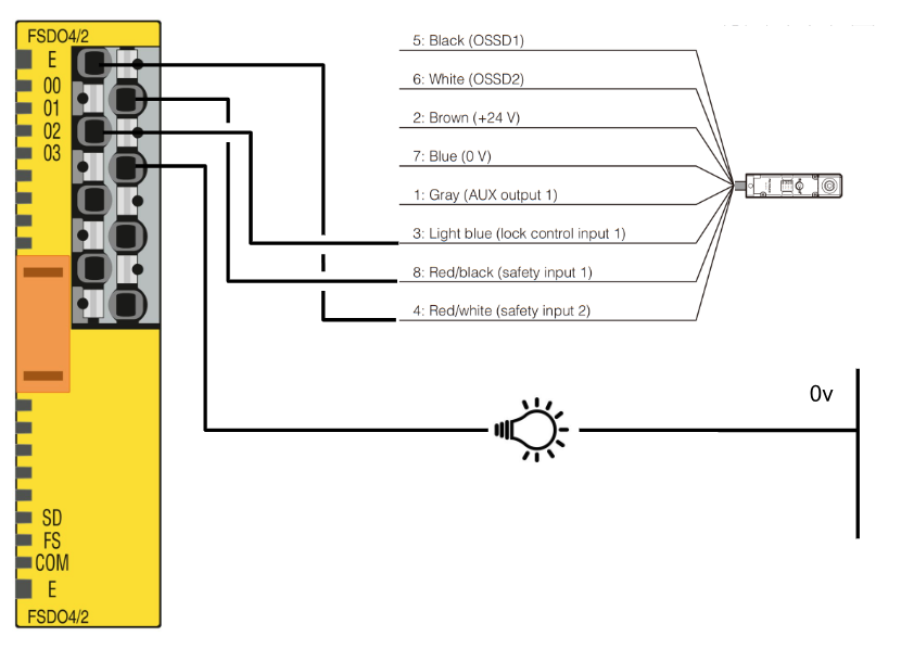
Wiring‐FSDO4/2
This is the wiring diagram for the FSDO4/2 safety output.
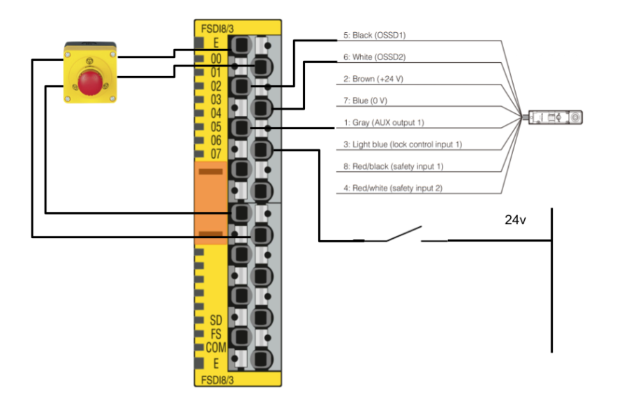
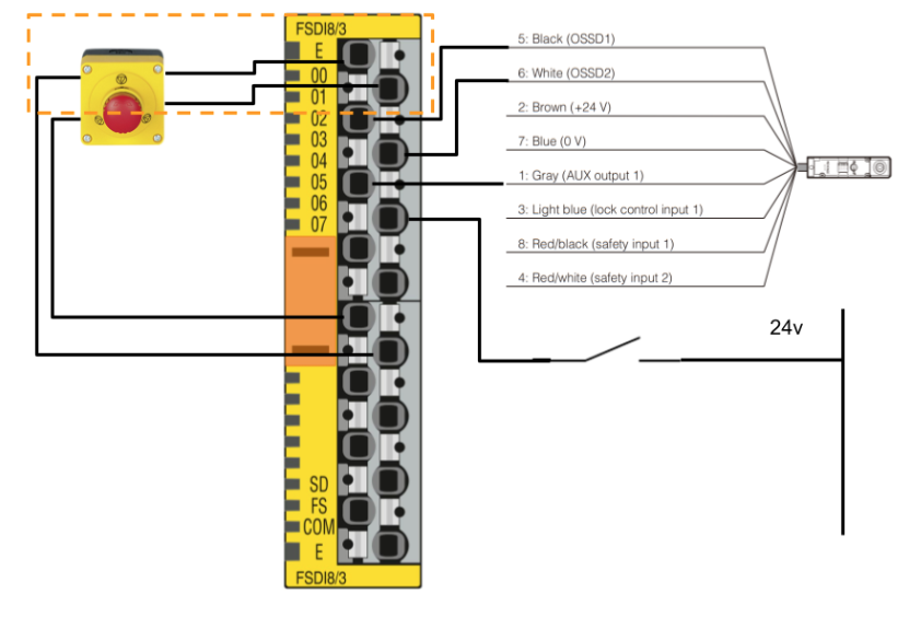
Wiring‐FSDI8/3
This is the wiring diagram for the FSDI8/3 safety input.
Setup F-Address
Set the FSOE address for FSDO4/2 and Wiring-FSDI8/3.
Beckhoff Side
Download ESI File
Download the ESI File for the AXL F BK EC EtherCAT Coupler from the Phoenix Contact website.
https://www.phoenixcontact.com/en-pc/products/bus-coupler-axl-f-bk-ec-2688899

Install ESI File
Store the ESI File downloaded earlier in the following Directory.
C:\TwinCAT\3.1\Config\Io\EtherCAT

Reload Configuration
Restart TwinCAT or reload the ESI Library via TwinCAT>EtherCAT Devices>Reload Device Descriptions.

EtherCAT Configuration
The next step is to build an EtherCAT network.
Configure via Scan Network
First use the TwinCAT Scan function to search for Slaves in the EtherCAT network.
EtherCAT>Right click>Scan.

Copy All
Click Copy All to duplicate the searched devices in the project.

Done!

Click OK to apply the settings.

Result
Done!

Configure via Manual
Right-click on EtherCAT Master > Add New Item, as it is unlikely that you will actually use Scan to build an EtherCAT network.

Select the EtherCAT Coupler in Phoenix Contact and proceed with Ok.

Next, select the Phoenix Contact EtherCAT Coupler you have just added > right-click > Add New Item.

Next, open the Slots screen.

Next, insert the Smart Element into each slot according to the actual hardware.

Done!

Safety Project
Now create a Safety project.
Add Alias Devices
Add AXL SE FSDO4/2 2A and AXL SE FSDI8/3 in the Phoenix Contact EtherCAT Coupler to the Alias of EP1957-0022.
Add Folder
The more safety devices you have, the more difficult it becomes to manage them, so add Folders.

Done!

Add Devices
The more safety devices you have, the more difficult it becomes to manage them, so add Folders.

Add one AXL SE FSDO4/2 2A and one AXL SE FSDI8/3 as they will appear in Safety>EtherCAT>Phoenix Contact.

Result
Done!

AXL SE FSDI8/3 Parameters
Set the parameters of the AXL SE FSDI8/3 safety input module.

FSoE Address
Set Linking>FSoE Address to match the DIP switch.

Conn-Id
Configure Connection>Conn-ld so that it is not covered by other FSoE devices.

Safety Parameters
Next, open the Safety Parameters Tab and configure the settings for each Input pair.

Input pair00
CH1 and CH2 of Input00 are wired as emergency stop.
Set 8000:03 used,2-channel equivalent (2).

Input pair01
CH1 and CH2 of Input01 are wired to the OSSD input of the Keyence GS-51P10 lock.
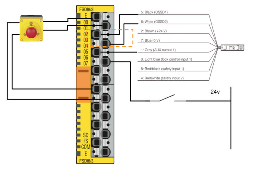
Set 8000:08 used,2-channel equivalent (2) and disable Cross-circuit Detection on 8000:0C.

Input pair02
CH1 of Input02 is wired to AUX output1 (door open signal) of the Keyence GS-51P10 lock and CH2 is wired to the Push-Button.
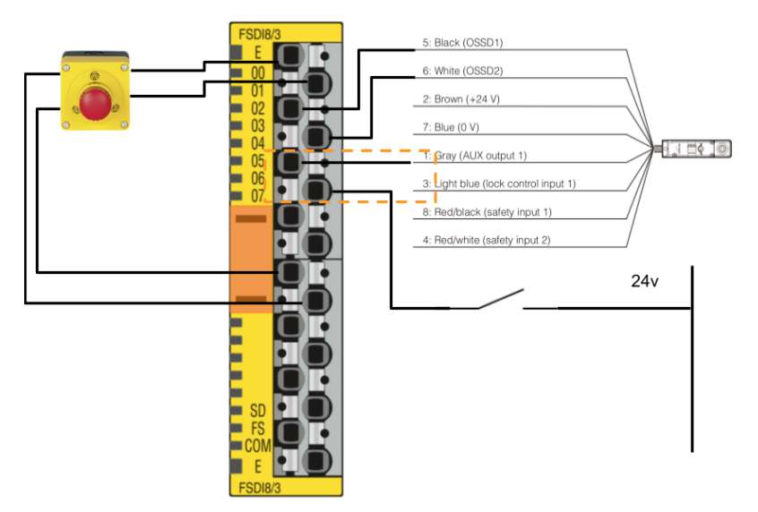
Set 8000:0D used,both 1-channel(1).

AXL SE FSDO4/2 2A Parameters
Sets the parameters of the AXL SE FSDO4/2 2A safety input module.

FSoE Address
Set Linking>FSoE Address to match the DIP switch.

Conn-Id
Configure Connection>Conn-ld so that it is not covered by other FSoE devices.

Safety Parameters
Next, open the Safety Parameters Tab and configure the settings for each Output pair.

Output pair00
CH1 and CH2 of Output00 are wired to the Lock signal Safety Input1 and Safety Input2 of the Keyence door lock.
Set 8000:03 to used,2-chnnel.

Output pair01
CH1 of Output01 is wired to the unlock input signal of the keyence door lock and CH2 is wired to the lamp output.
Set 8000:08 to used,1-chnnel.

Safety GVL
The next step is to define safety variables so that safety inputs and outputs can be used within the safety programme.
- FIN_ESTOPCH1
- Safety stop input 1
- Safety input module 1 channel 1
- FIN_ESTOPCH2
- Safety stop input 2
- Safety input module 1 channel 2
- FIN_DoorLock_Signal
- Door closed signal
- Safety input module 3 channels 1️.
- FIN_DoorLock_InputChannel1
- Door locked signal 1
- Safety input module 2 channels 1️.
- FIN_DoorLock_InputChannel2
- Door locked signal 2
- Safety input module 3 channel 2
- FIN_ReleaseLock
- ドアロックをリリースするPushボタン
- 安全入力モジュール2チャンネル2
- FIN_ETSOP2
- Second safety stop input.
- AXL F BK EC – Wiring-FSDI8/3 safety input IN0, CH1 and CH2 on Bus coupler
- FOUT_DOORLOCK2
- Safety Input2 and Safety Input1 of the keyword lock
- AXL F BK EC – Bus coupler Wiring-AXL SE FSDO4/2 2A Safety Output, CH1, CH2
- FOUT_Safety Channel2
- Safety Input2 on Pilz door locks
- Safety Output module 3
- FOUT_Safety Channel1
- Safety Input1 on Pilz door locks
- Safety Output module 4
- FOUT_LockUnlock
- Unlock signal with keyword lock
- AXL F BK EC – Wiring-AXL SE FSDO4/2 2A safety output on Bus coupler, CH3
- FOUT_OKLAMP
- Lamp output.
- AXL F BK EC – Wiring-AXL SE FSDO4/2 2A safety output on Bus coupler, CH4

Safety Program
The next step is to create a TwinSAFE safety programme.
Network1
As mentioned before, TwinSAFE only allows one safe variable in one place, so use safeDecouple to expand the safe input into multiple Local safe variables.

Network2
This is a programme to check the status of two emergency stops that have been released.

Network3
Network3 is a door lock release and lock control programme.

The emergency stop must be released and the door must be currently in the close position for the door lock command to be executed.

The door lock gets a 1s confirmation and the result of the operation is used as the Set input for safeRs.

When the Set input is switched on, RsOut is set to True and the output is set to True on the Safety Input channel of the door lock.

When the release button is pressed, the output is set to False on the Safety Input channel of the door lock.

The next step is to use safetTon to make the door lockable status a one second delay.
 Network4
The next step is to use safetTon to make the door lockable status a one second delay.

Network5
Feedback of the lock signal to the Normal PLC.

Network6
At the end, the internal variables of the safety programme are transferred to the safety outputs.
It also outputs a LAMP with the lock OK.

Verify Safety Project
To display the button for TwinSAFE, click View>Toolbars>TwinCAT Safety.

The next step is to compile a safety project with Verify Safety Project.

Done!There are no errors in the compilation results.

Download
Download the safety programme to EP1957-0022 at Download Safety Project.

Default Username is Administrator and Default Password is TwinSAFE.

The serial number of EP1957-0022 is next to the actual machine.

Select Complete Project Data and proceed with Next.

Proceed with Next.

Check Box and proceed with Next.

Enter the password one last time.

Activate Configuration
Press Activate Cofiguration to Download the Hardware Configuration to TwinCAT Runtime.

OK to proceed.

Switch TwinCAT Runtime to Run Mode.

Login
Download the programme in Login.

Proceed with Yes.

Start
Finally, start the TwinCAT Runtime with the hStart button.

Result
You can check the operation from this video.
Beckhoff.Play with EP1957-0022 and Pilz,Keyence Door Lock
Download
Download the TwinCAT project for this article here.
https://github.com/soup01Threes/TwinCAT3/blob/main/TwinSAFE%20EP1957-0022-Part3-2DoorLocks.tnzip