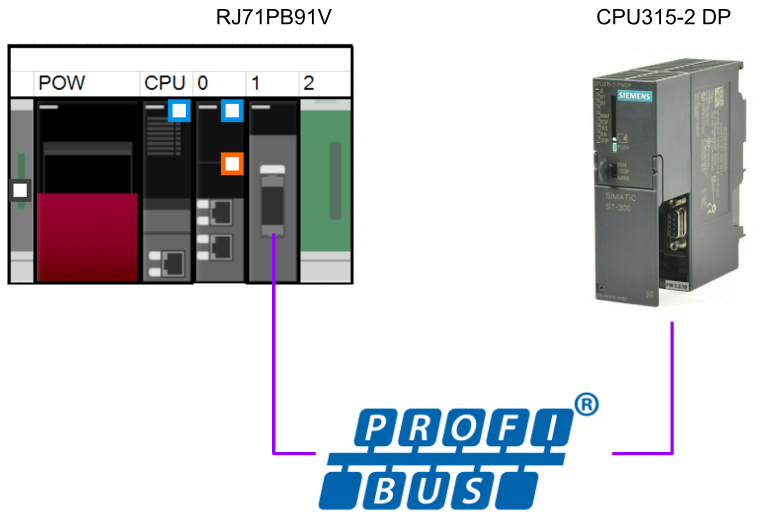
In this article, we will use IQ-R’s RJ71PB91V module to set up Profibus Master and connect it to Siemens’ CPU 315-2 DP.
Let’s get started!
Reference Link
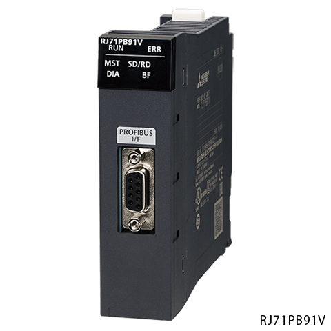
RJ71PB91V?
The RJ71PB91V used in this article can operate as a Profibus Class 1 Master station, with a communication speed of
It can support communication speeds from 9.6 kbps to 12 Mbps. It can also build a Profibus network with up to 32 stations per segment and up to 126 stations per network.
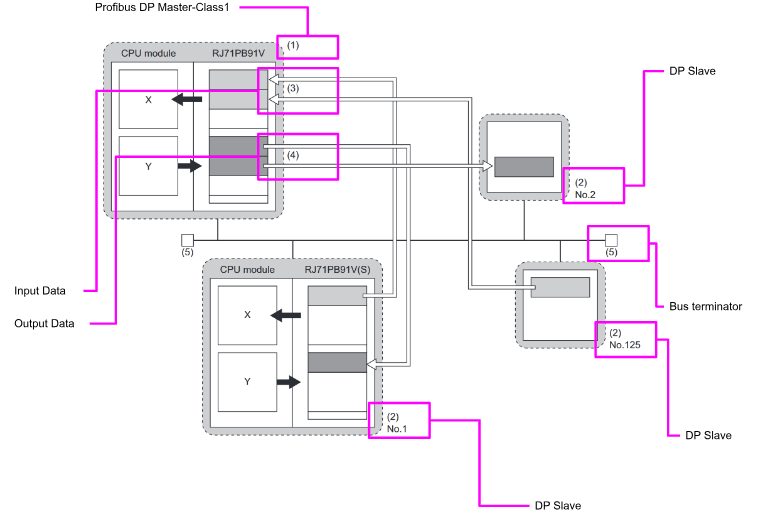
The RJ71PB91V main unit has 32 occupied I/O points, enabling control of the module main unit and status acquisition.
The function of IO data exchange is shown in the figure below.
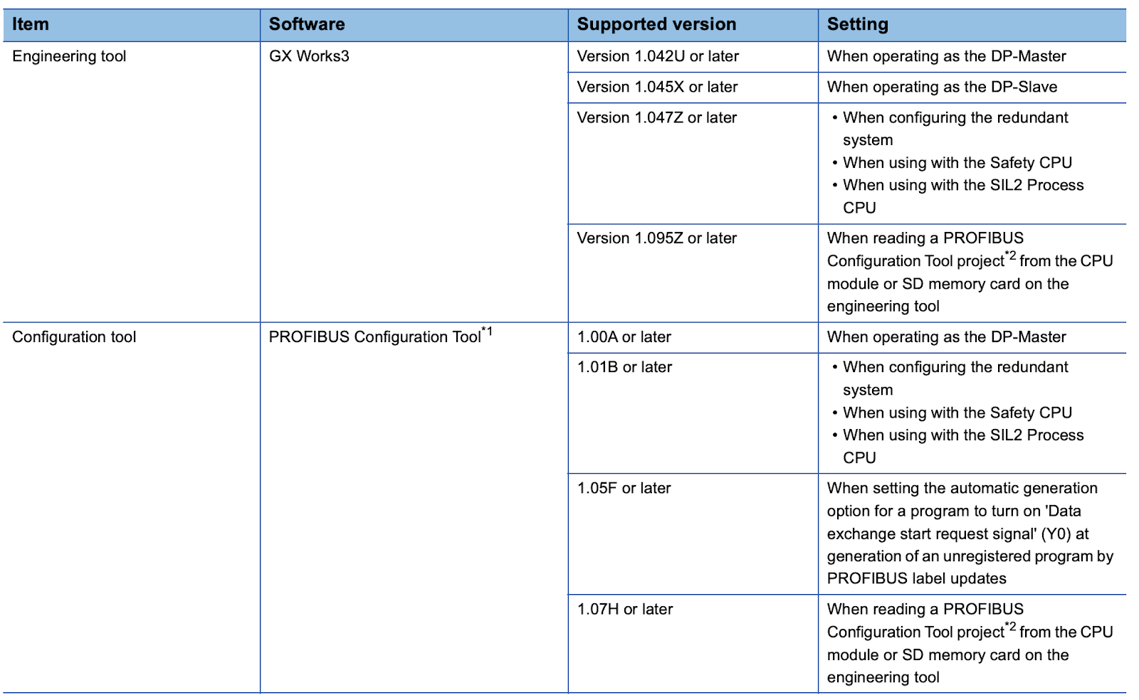
Software Requirment
This is the GXWORKS3 Version and Tool Version when using RJ71PB91V.
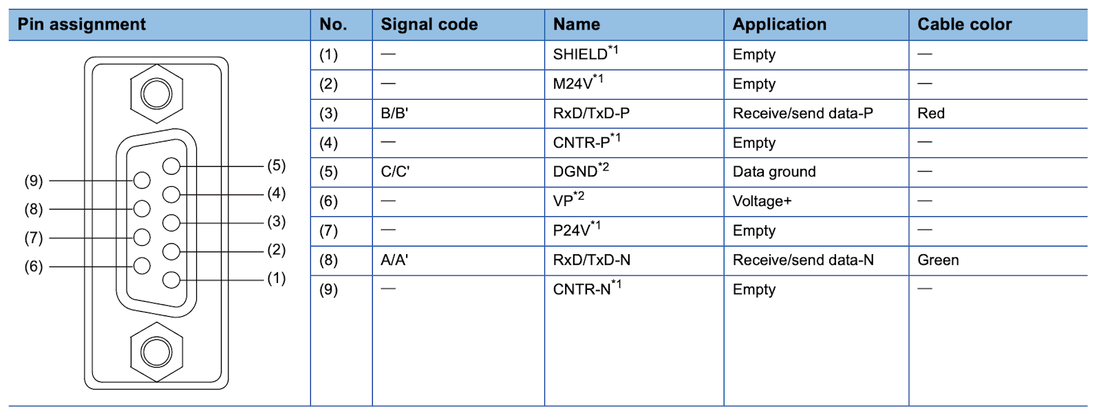
Wiring
This is the profibus wiring.
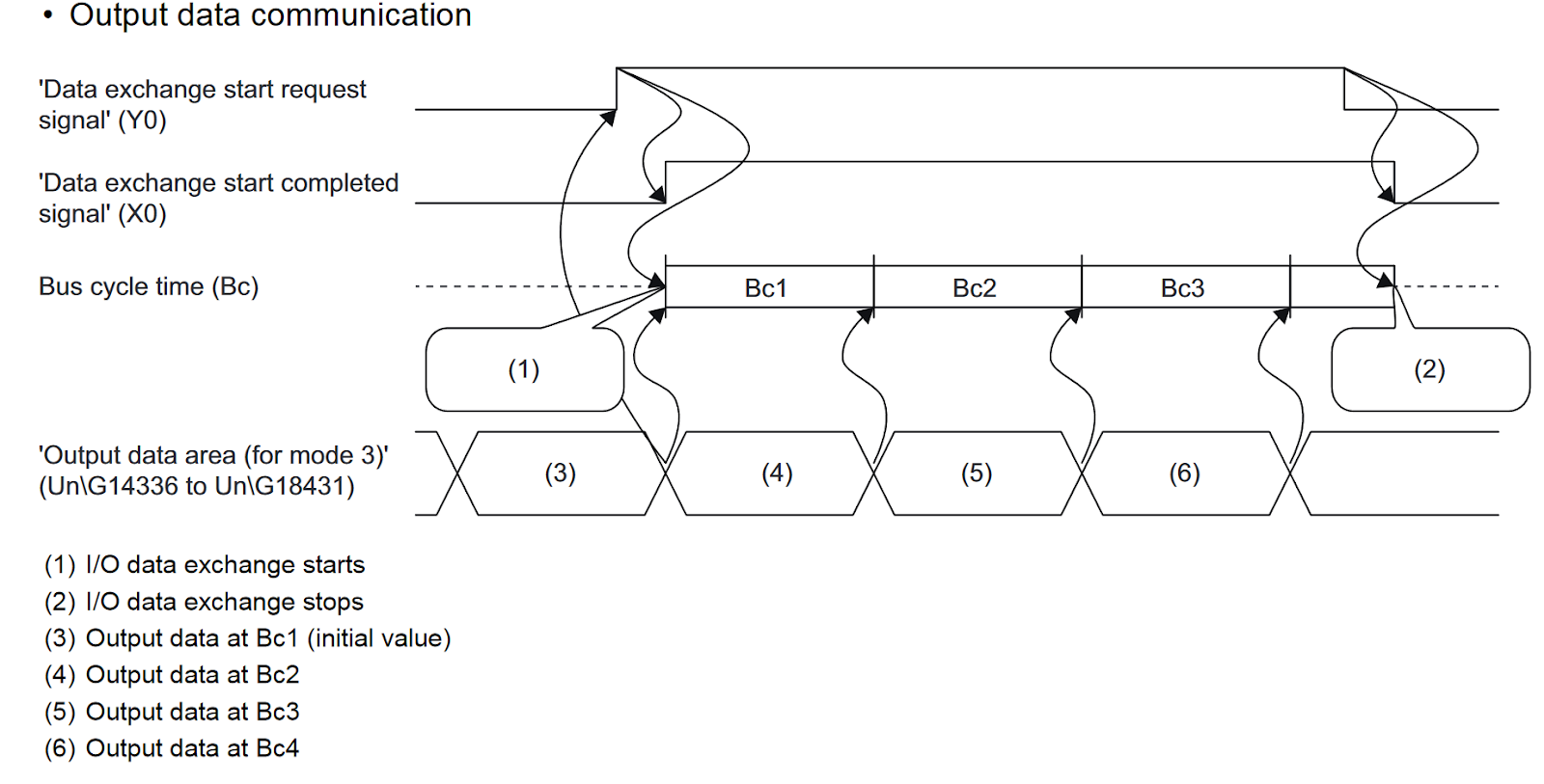
Time Chart‐ Output Communication
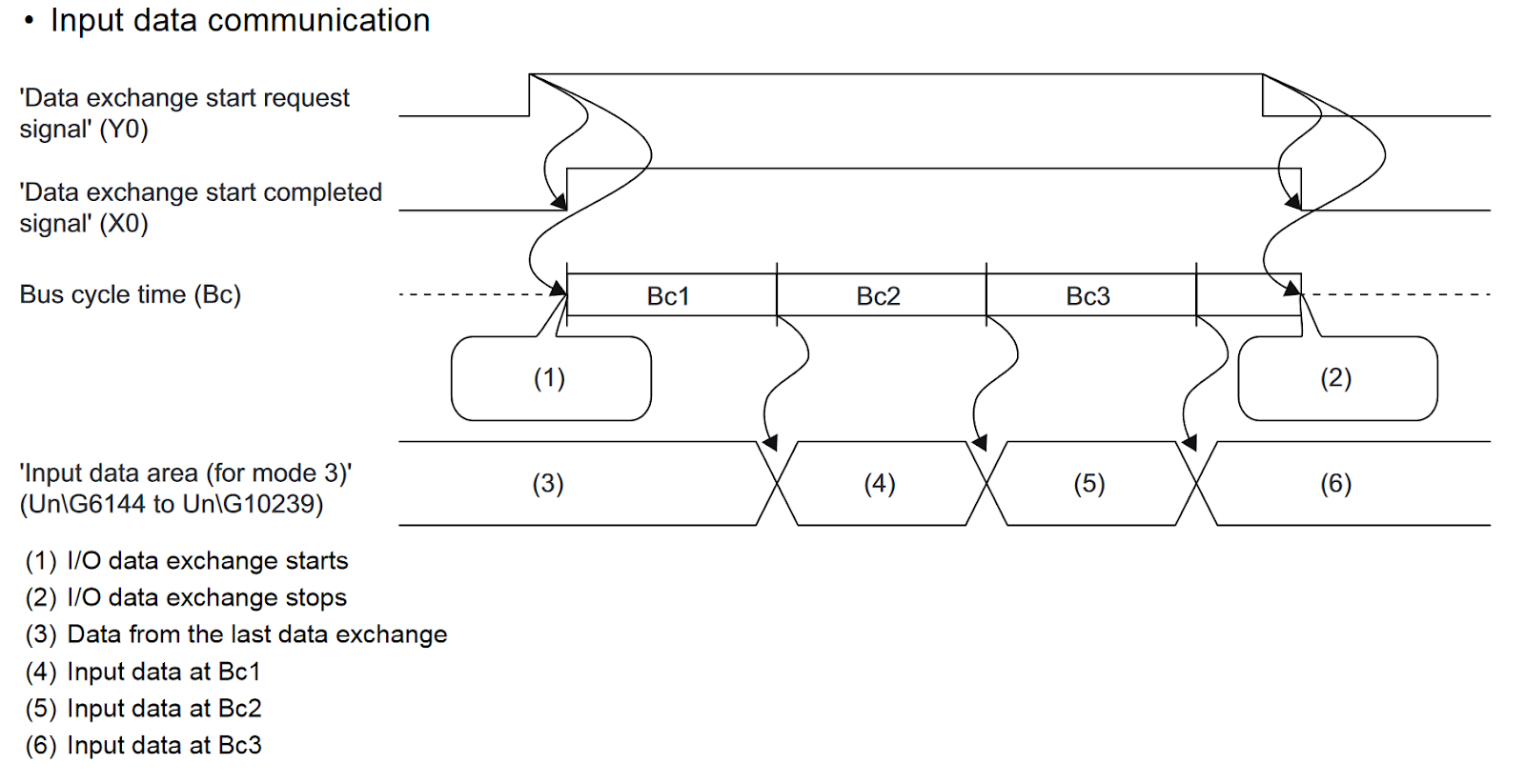
Time Chart‐ Input Communication
Configuration Example
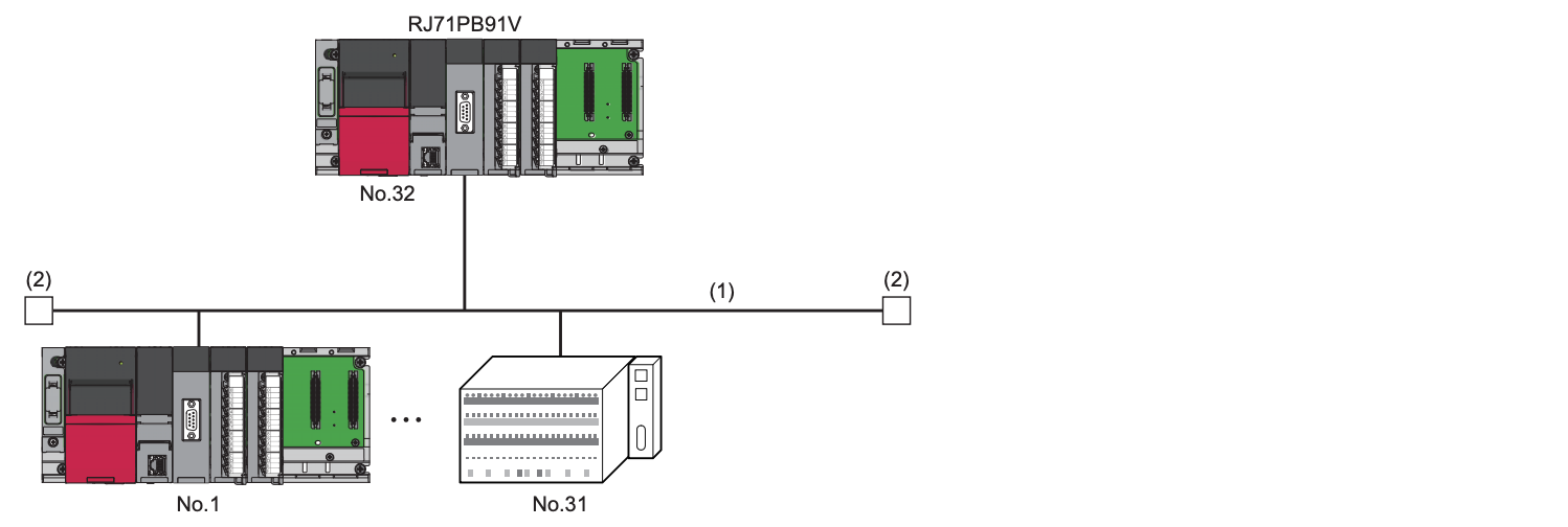
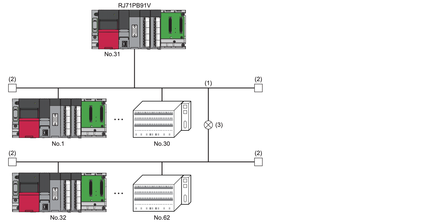
Maximum configuration of segment
This is an example of 1 Segment configuration, with a maximum of 32 modules per Segment.
Maximum configuration of network (using one repeater)
With Repeater, two Segments can be linked as a single Network.
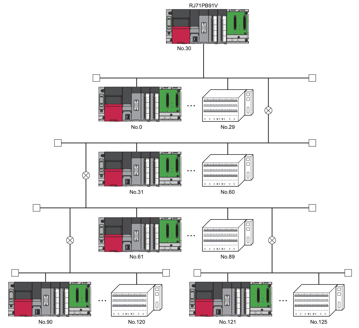
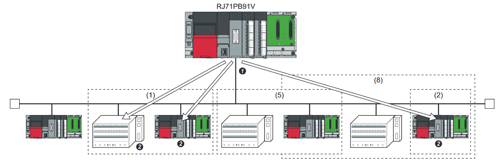
Maximum configuration of network (using three repeaters)
This is an example of using three Repeater.DP master and DP slave can be connected within the FDL address setting range (0 to 125).
Install Profibus Configuration Tool
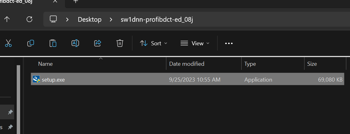
Download the Profibus Configuration Tool for Mitsubishi RJ71PB91V from the Link below.
Setup.exeをダブルクリックし、インストールを開始します。
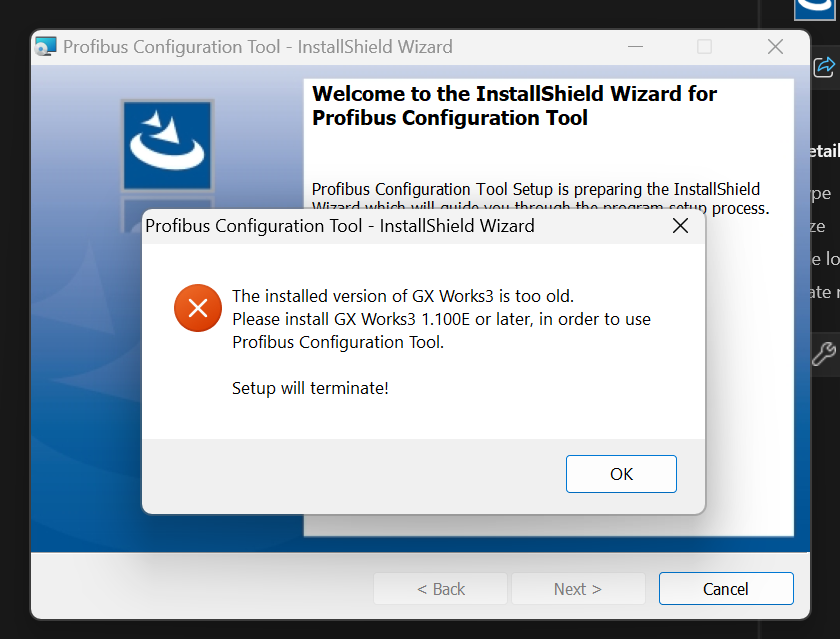
GXWORKS3 requires at least 3.1000E, so please download the GXWORKS3 Update File from Mitsubishi’s website and install it.
Proceed with Next>.
Enter brief personal information and proceed with Next>.
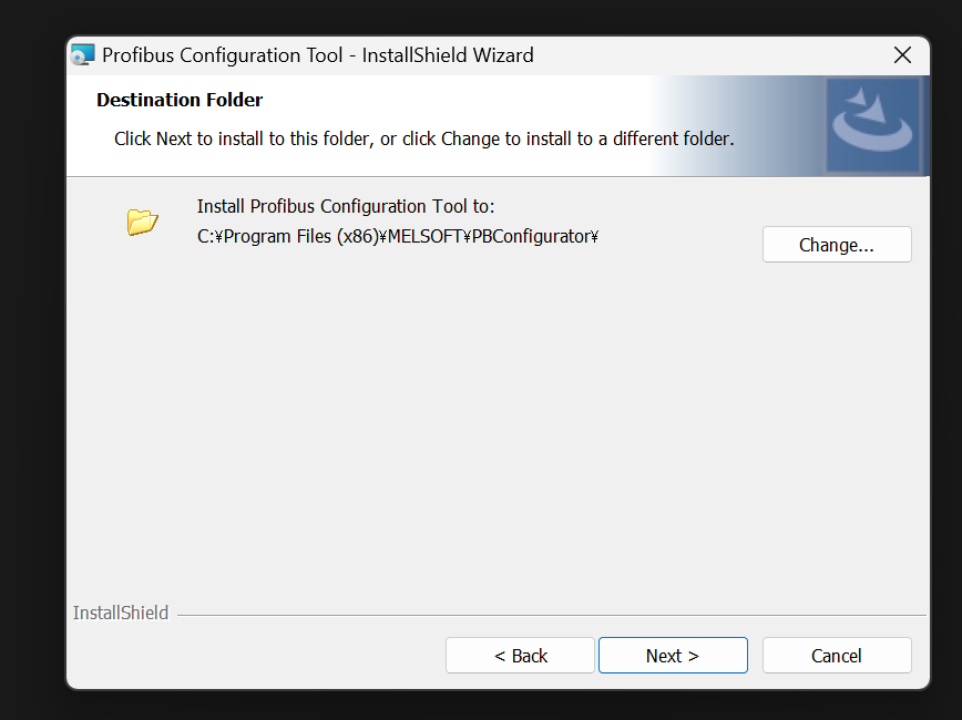
Set the installation location and proceed with Next>.
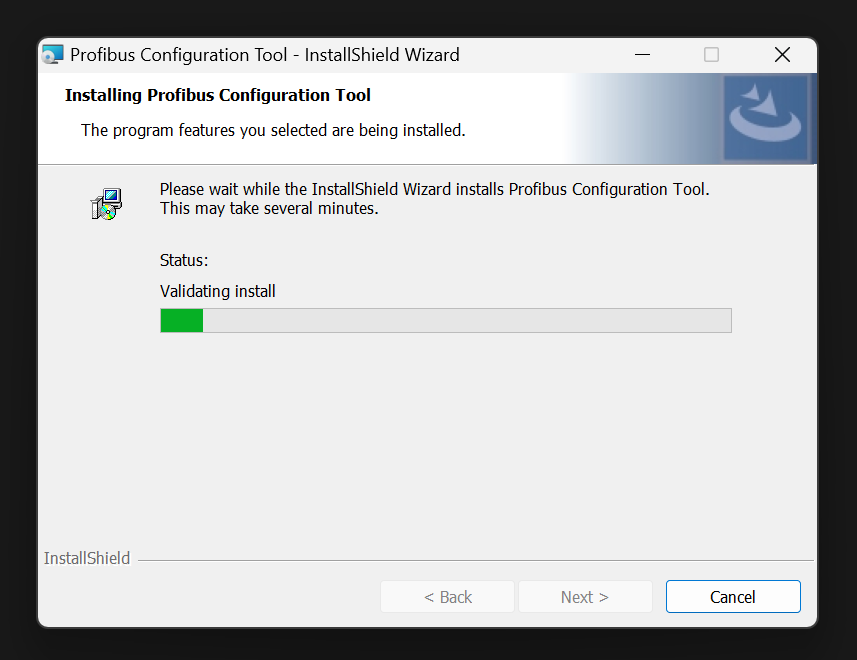
Start Install!
Just a second..
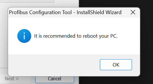
Restart your PC after installation is complete.
Done!
Download GSD File
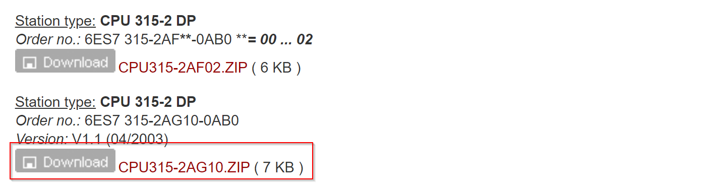
The Profibus Slave used in this article is Siemens’ CPU 315-2 DP, so please download the CPU 315-2 DP GSD File from the link below.
https://support.industry.siemens.com/cs/document/113652/profibus-gsd-files-simatic?dti=0&lc=en-JP
Implementation
Siemens Side
Start building from the Siemens CPU 315-2 DP side.
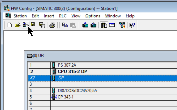
Hardware Configuration
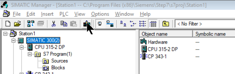
Double-click S7300 Station.
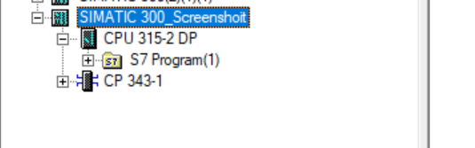
Open the Hardware item inside.
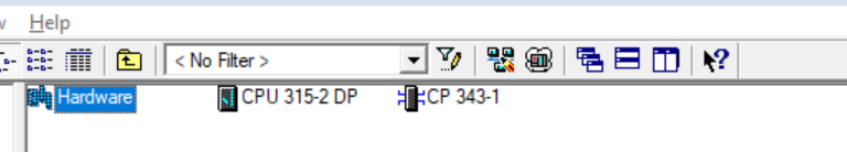
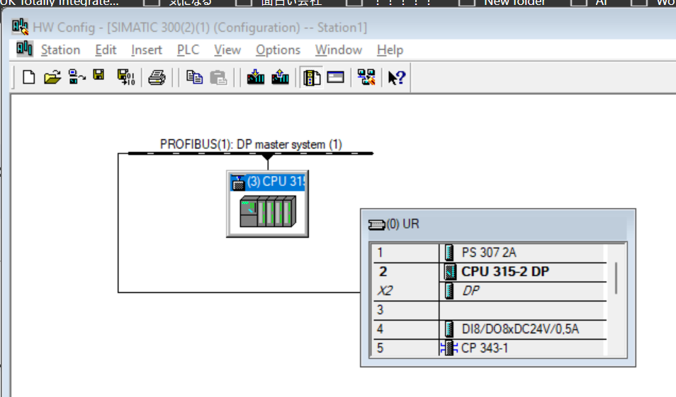
This is the screen for building Hardware Configuration for CPUs such as the S7-300.
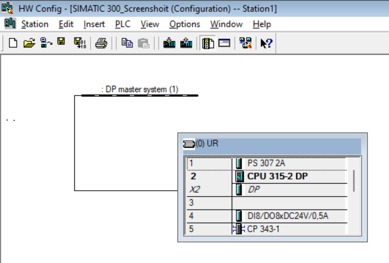
Configure DP
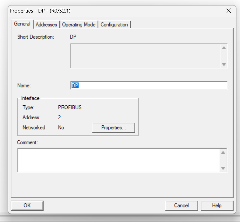
The DP Port of the current CPU 315-2 DP is set as Profibus Master.The Mitsubishi IQ-R RJ71PB91V used in this article can only support Profibus Master, so the CPU 315-2 DP must be set as Slave.
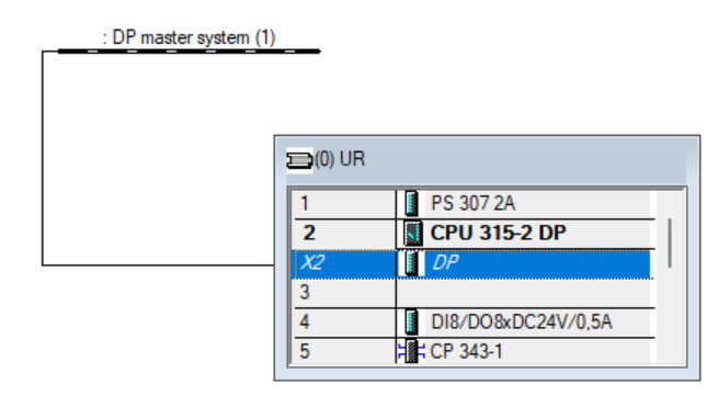
This is the DP Port setting screen.
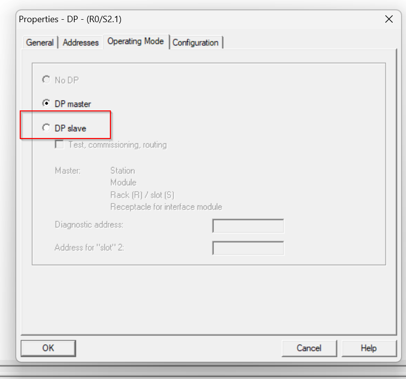
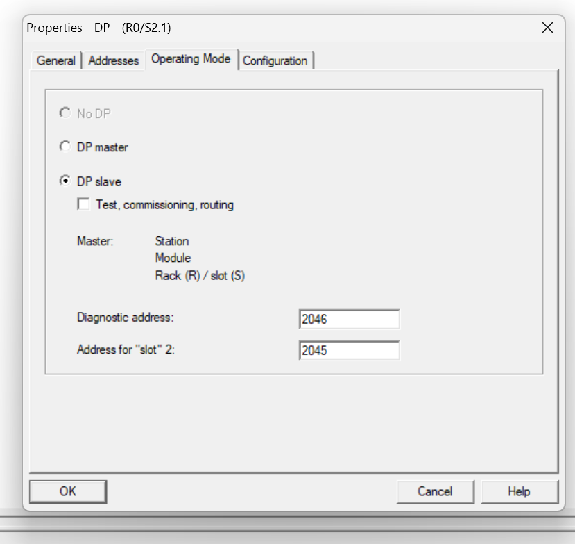
Operating Mode
Open the Operation Mode tab and set DP slave.
Done!
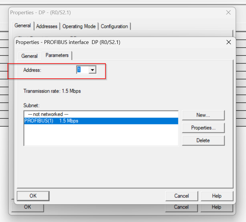
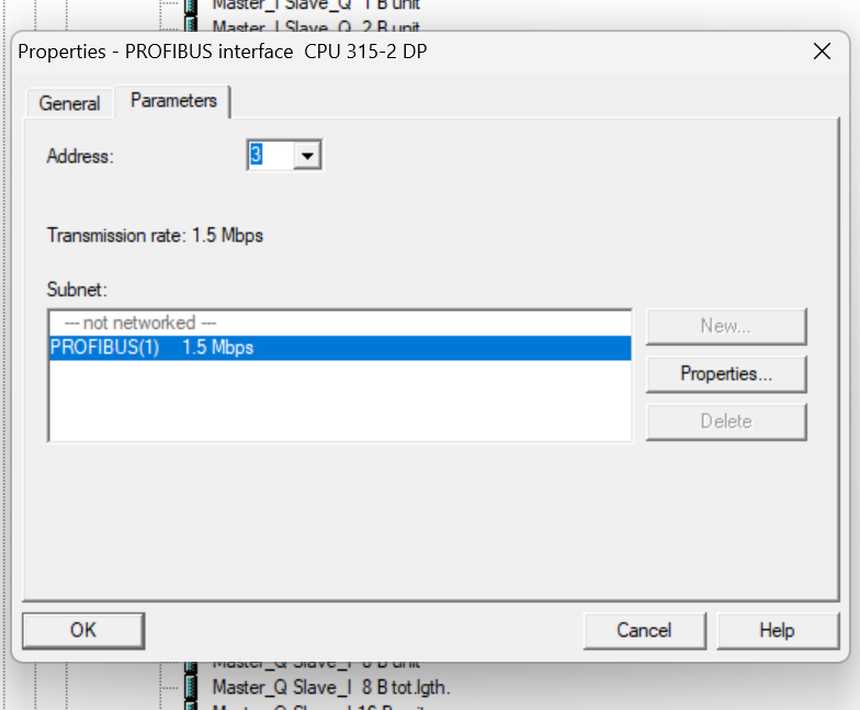
Node Address
Now the DP Port is running as a Slave, but we need to set the Profibus address.
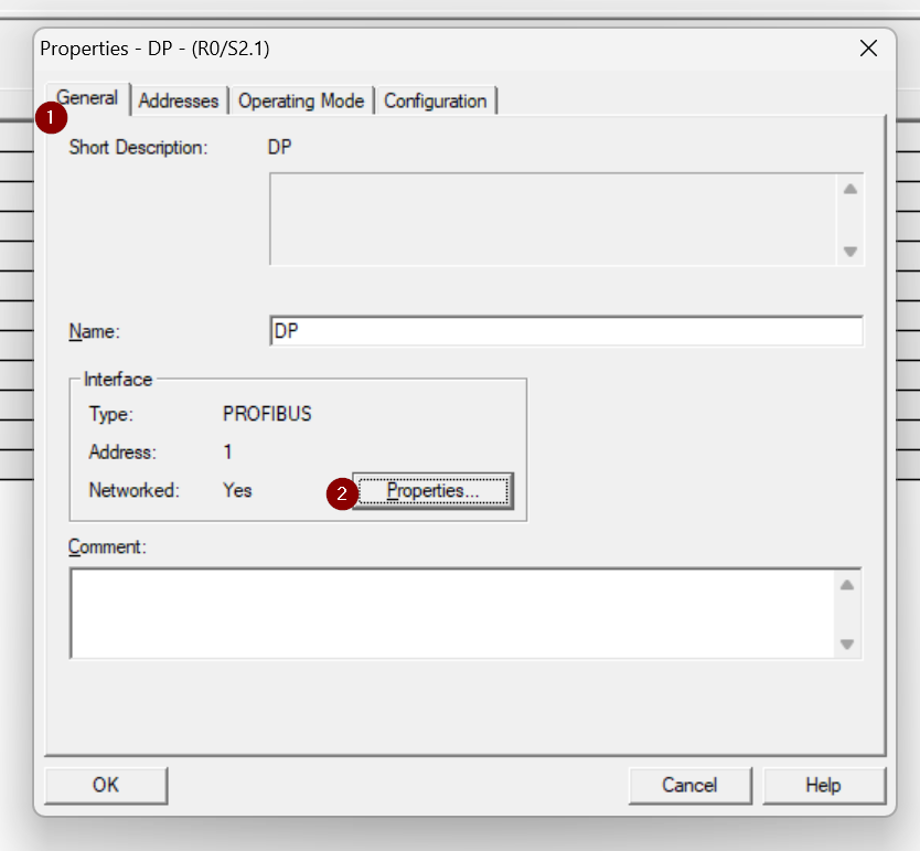
Set the address of Profibus according to the application from the Address item in the Parameters Tab.
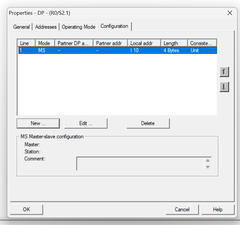
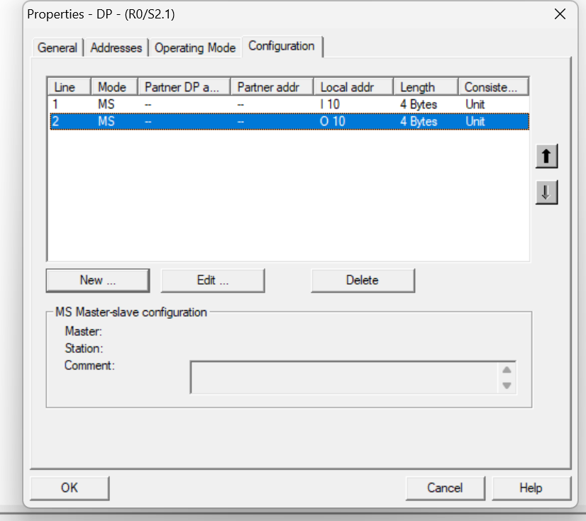
Configuration
Finally, open the Configuration Tab and define the data mapping to be exchanged between DP Slave and Master.The CPU 315-2 DP has no fixed slots, allowing the input/output memory area to be freely configured to suit the application.
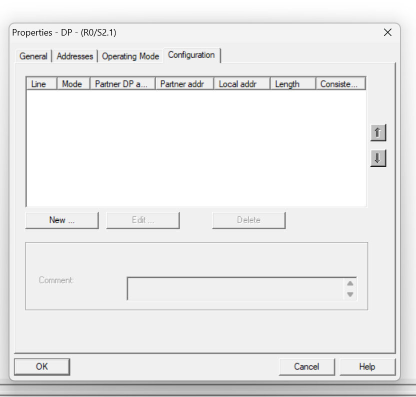
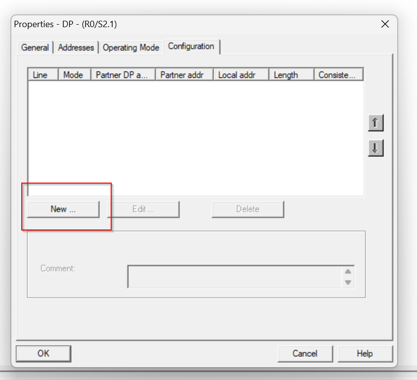
Add Input Data
Click the New button to define a new data exchange area.
The Properties settings screen for the slot will appear.
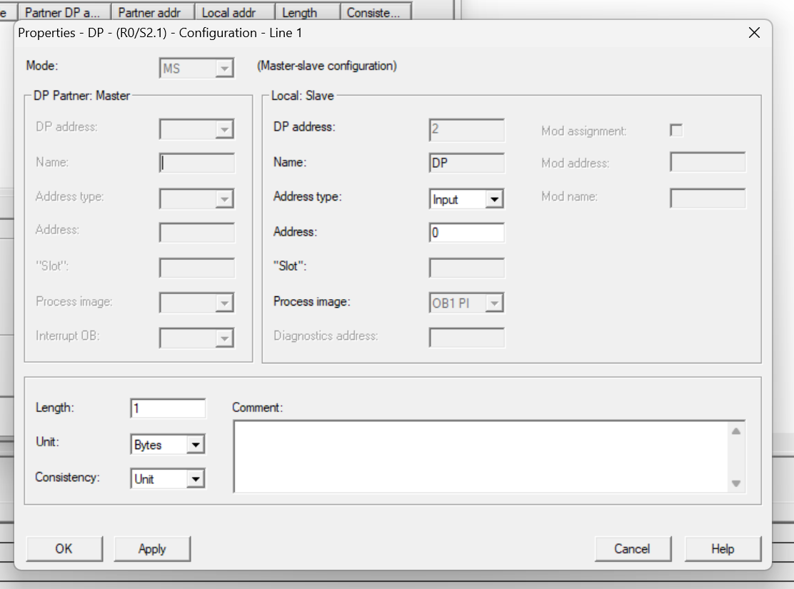
Address Type can change the input and output of the slot that is currently set.
Address sets the address Offset of the corresponding Slot. (I=Input, Q=Output)
Length is the memory size of the corresponding Slot.
Unit is the data type of the corresponding Slot.
In the figure below, Slot is set as the input and Address starts with 10, for a total of 4 Bytes of input data.
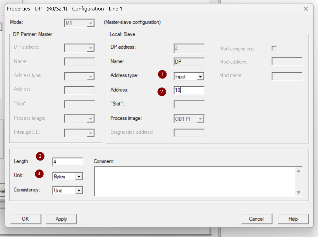
Done!Slot defined.
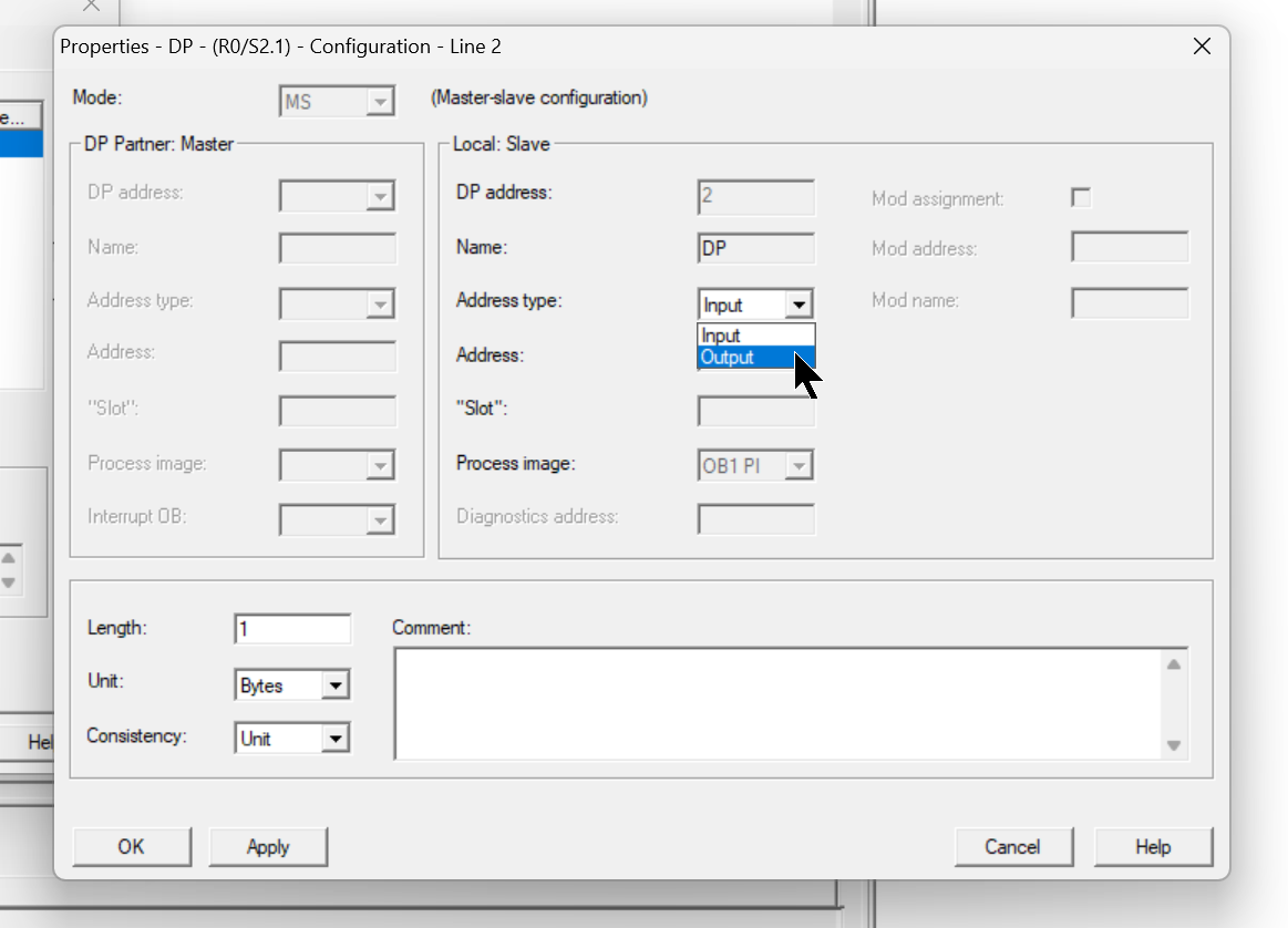
Add Output Data
Next, set the output data in the same way as before. This time, set the Address Type to “Output.
In the figure below, Slot is set as the input and Address starts with 10, resulting in a total of 4 Bytes of output data.
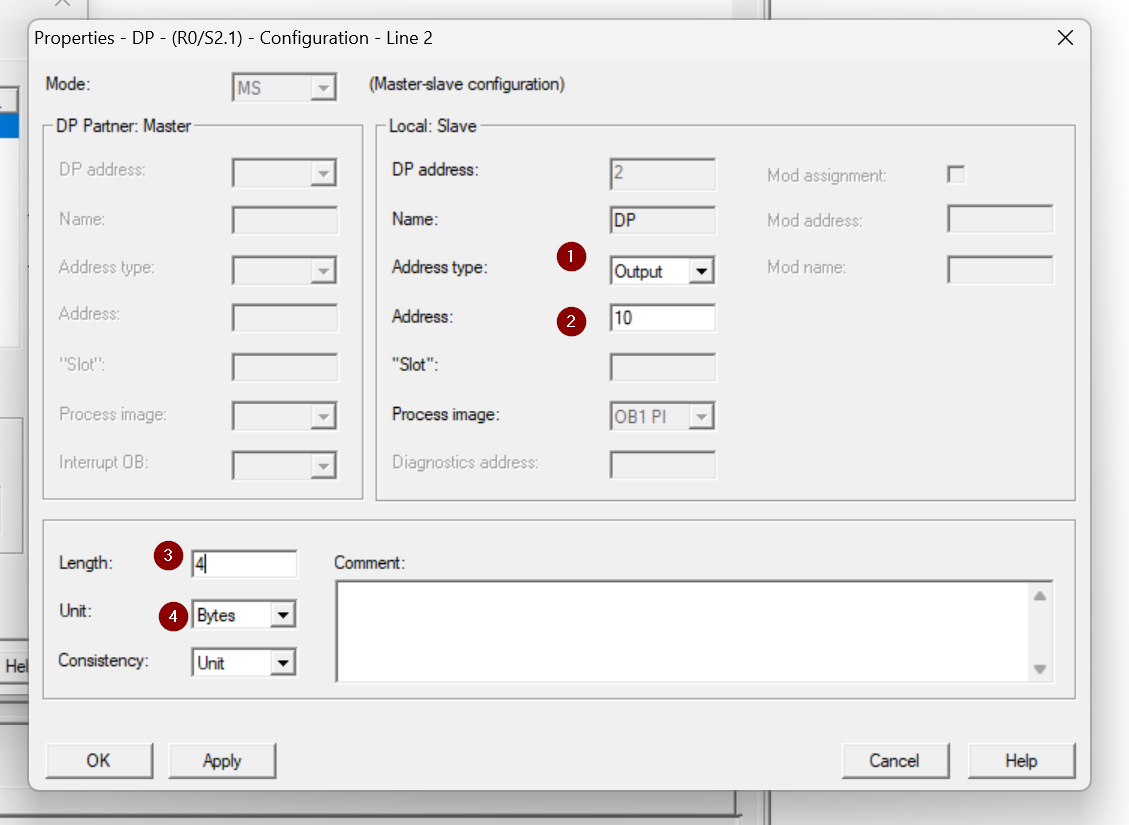
Done!
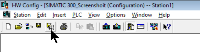
Save and Compile
Next, we will compile Hardware Configuration.
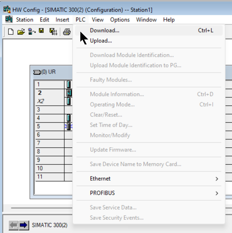
Download
Finally, use PLC>Download to download the Hardware Configuration to the CPU.
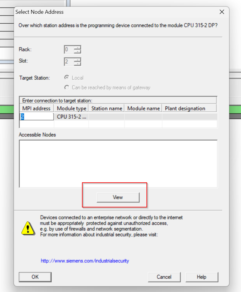
Select the CPU 315-2 DP used in this article and proceed with Ok.
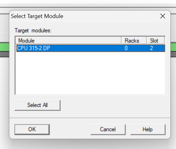
View searches for devices currently connected to the PC.
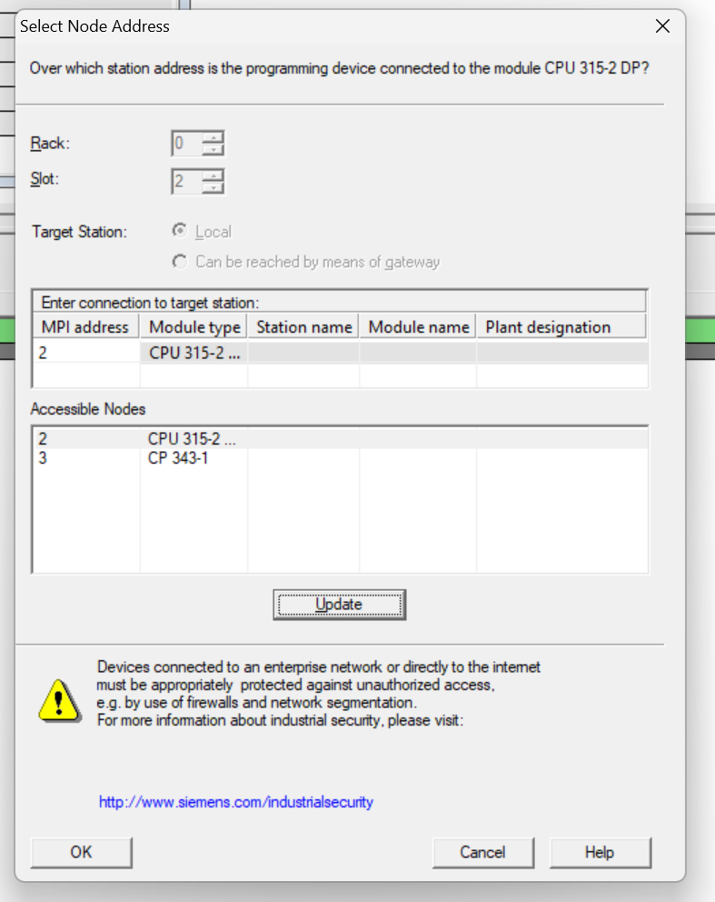
Done!CPU 315-2 DP is found, click OK and Download Hardware Configuration to CPU.
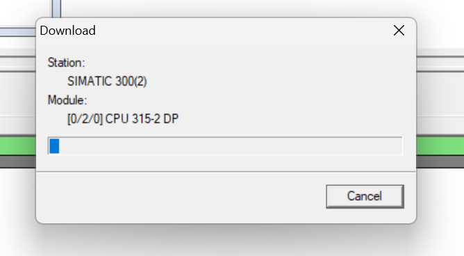
Just a second..
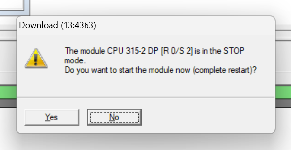
Done!The Yes button switches the CPU to Run Mode.
Mels Side
Now we will build the Mitsubishi IQ-R side.
Module Configuration
Add RJ71PB91V in Module Configuration.
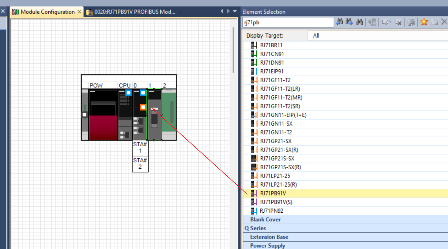
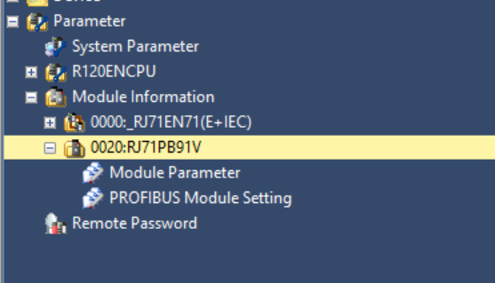
Done!There is a RJ71PB91V in the Folder of Module information.
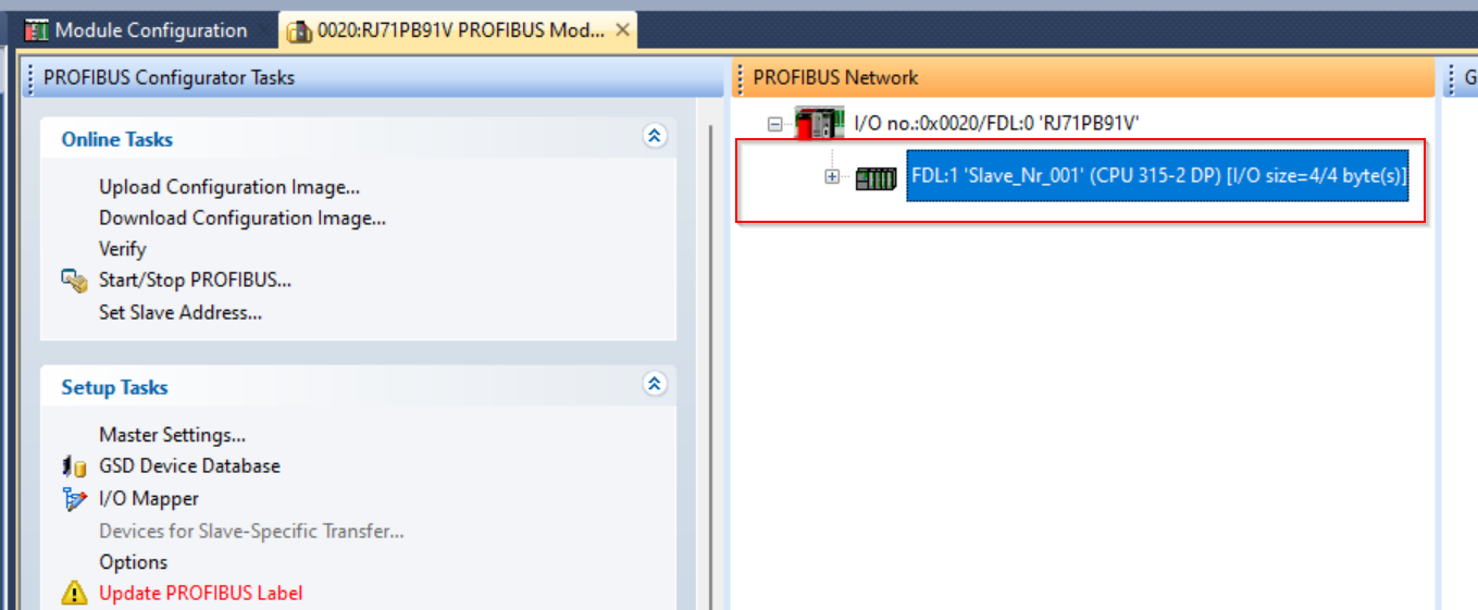
Configure PROFIBUS Network
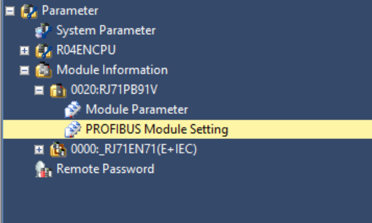
To set up a Profibus network, double-click Module Information>RJ71PB91V>PROFIBUS Module Setting.
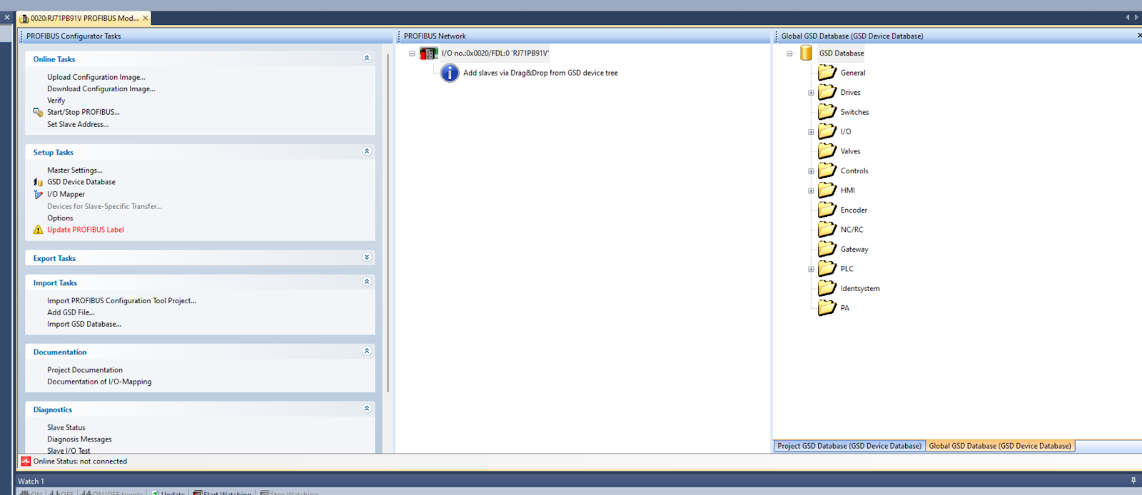
Once the PROFIBUS Configuration Tool is installed, another software program is automatically started.
Add GSD File
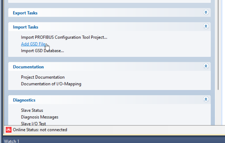
To build a Profibus network, you need to import a GSD File, so go to Import Tasks>Add GSD File to add a GSD File.
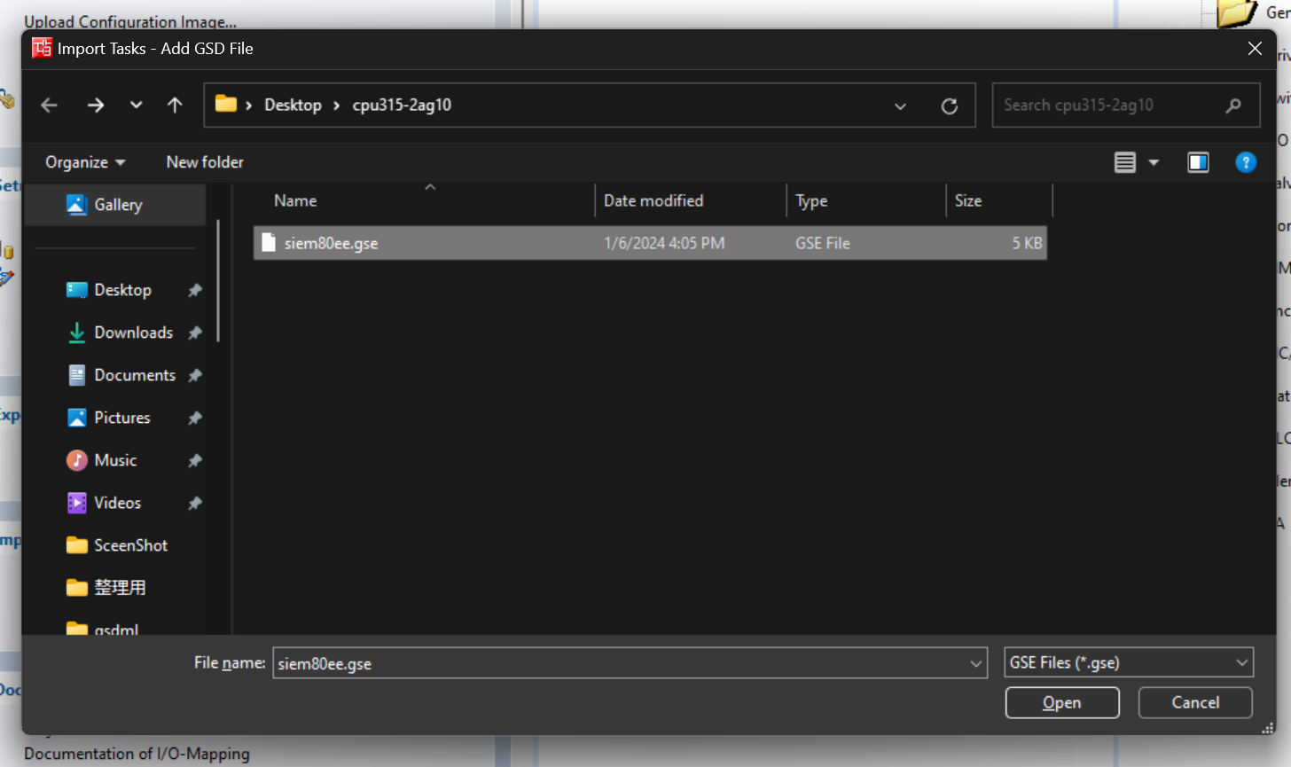
Set the Folder where you are in the CPU 315-2 DP ZIP File downloaded from Siemens HP and select GSE.
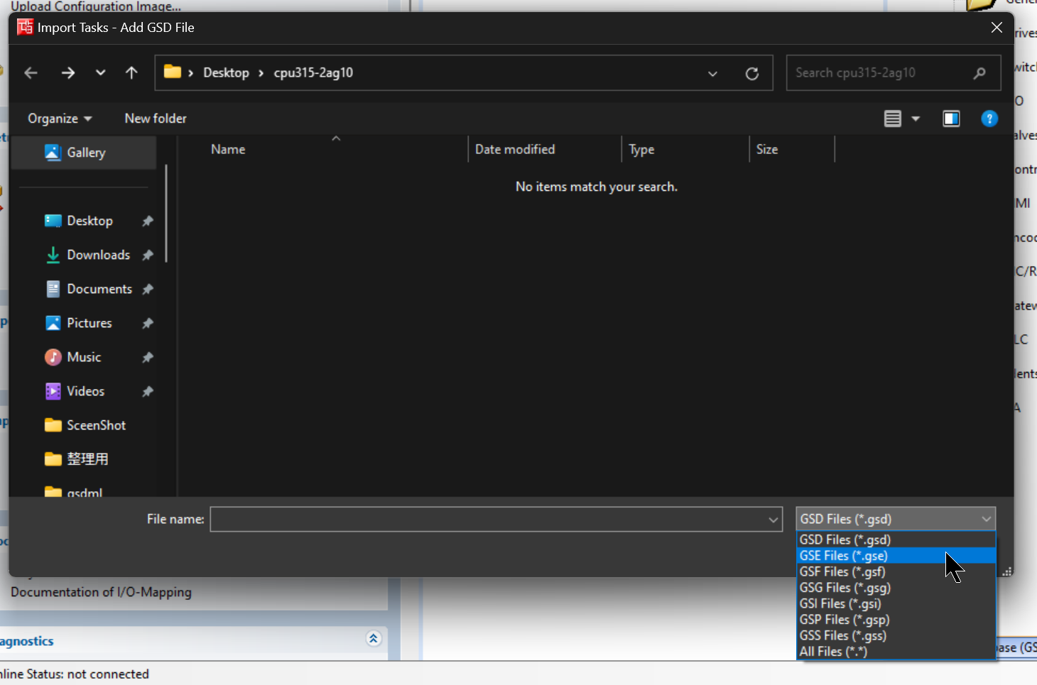
Select GSE > Open to import a File.
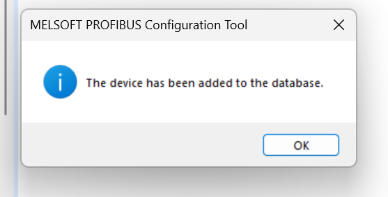
Do you want to add the corresponding GSD File to the database?Proceed with Yes.
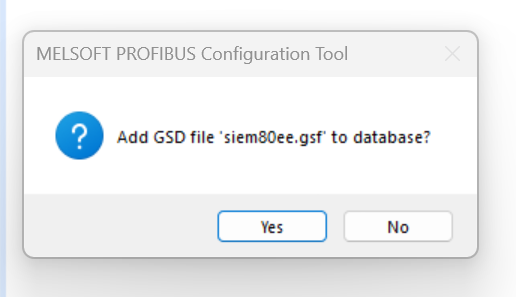
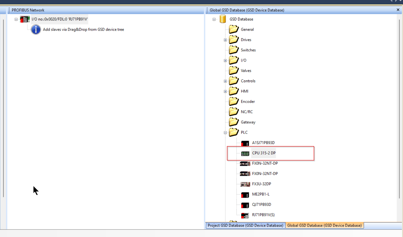
Done!
we found the CPU 315-2 DP that just added to GSD Database>PLC.
Add Siemens CPU
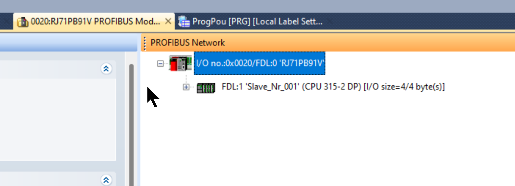
Add the CPU 315-2 DP to your Profibus Network.
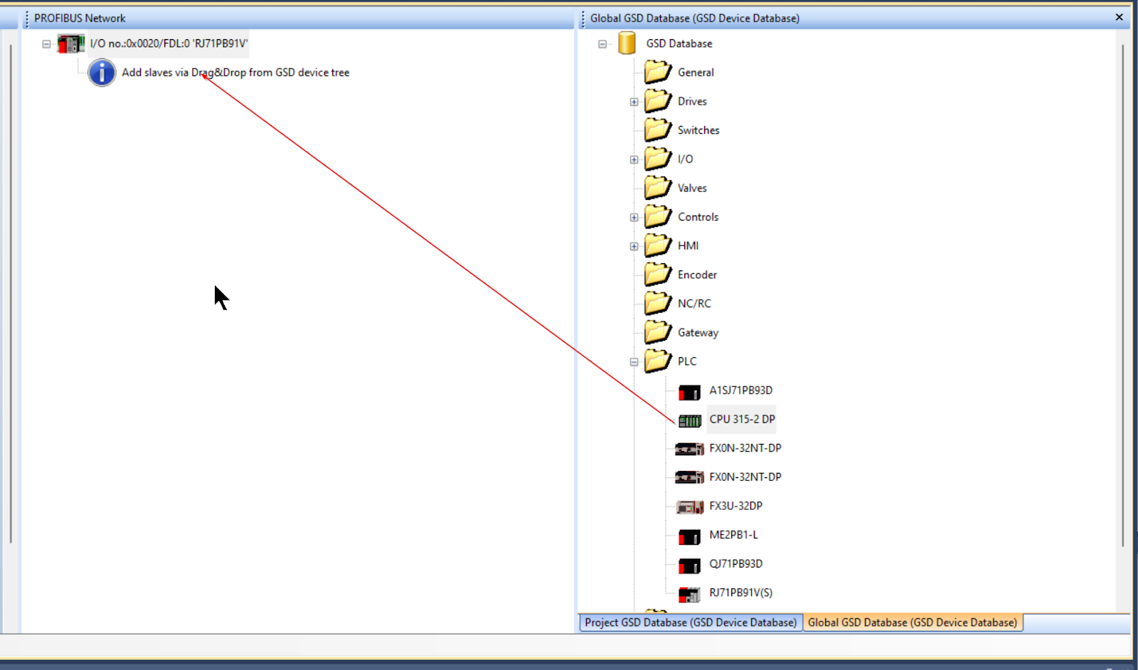
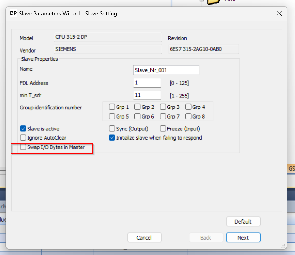
Slave Settings
The Slave Settings screen appears.
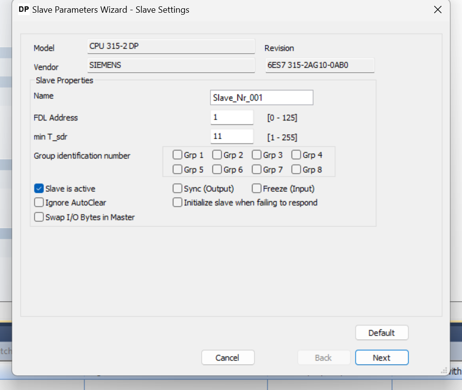
FDL Address
The FDL Address is the address of the Profibus Slave.
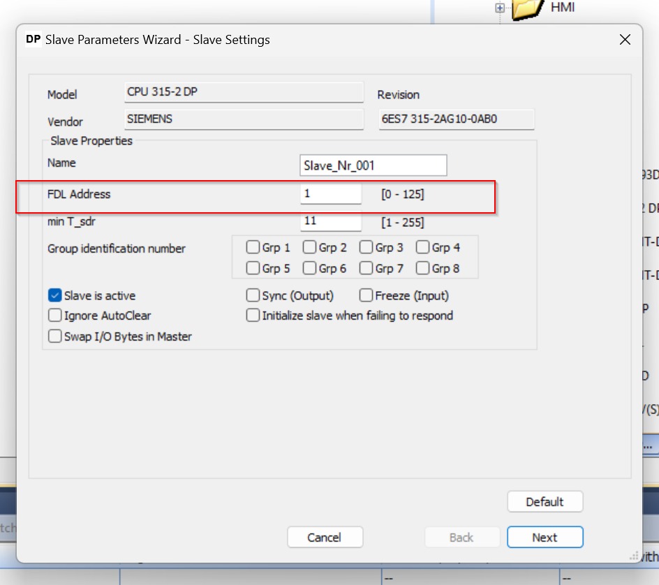
This article will be set to “1”, which was set earlier on the Siemens side.
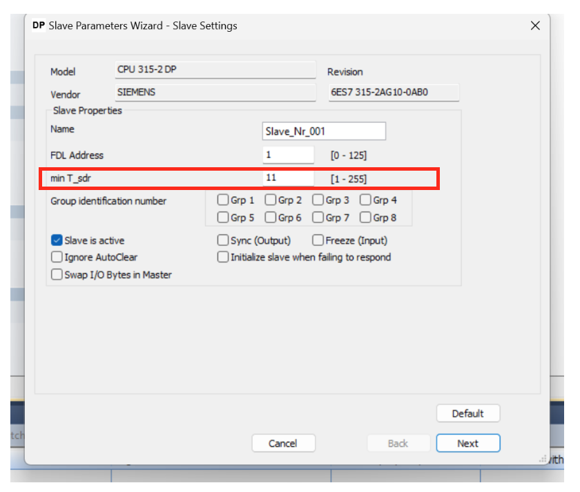
min T_sdr
min T_sdr can set Watchdog Timer for communication (Unit: 10ms).
If DP-Slave fails to receive data from DP-Master within the specified time, DP-Slave detects a communication timeout.
Group identification number
Although not used in this article, the Group identification number can be set to the Group number of the corresponding Slave.
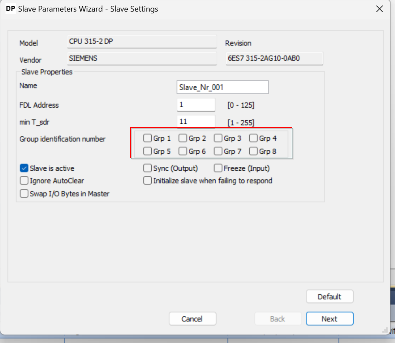
The Group function controls DP-Slaves belonging to a specified group simultaneously by sending services via multicast from DP-Master to hold/clear I/O data. DP-Slaves belonging to the specified group can then automatically hold/clear I/O data according to the received service.
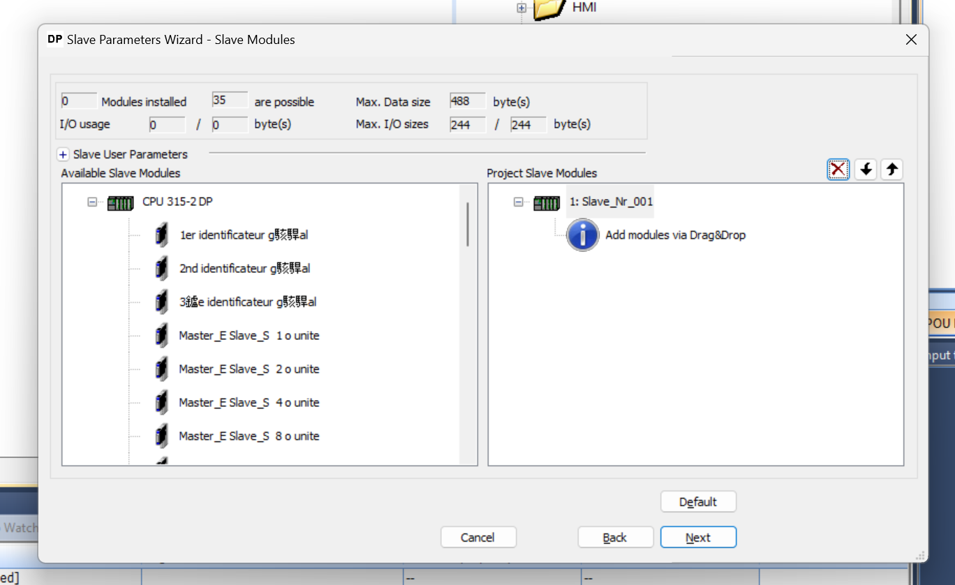
Slave Module
Click the Next button, and this time you will be taken to the Slave Modules setup screen.
However, the Slot of CPU 315-2 DP seems to be a bucket letter, let’s import the GSD File of CPU 315-2 DP from Step7 Classic once and see what kind of Slot is inside.
Test GDS File In Step7
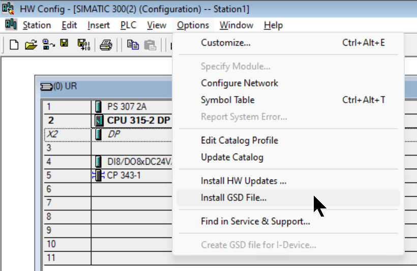
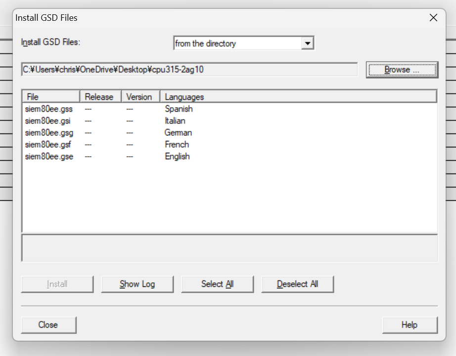
Start Step7 Classic again and install the GSD file by Options>Install GSD File.
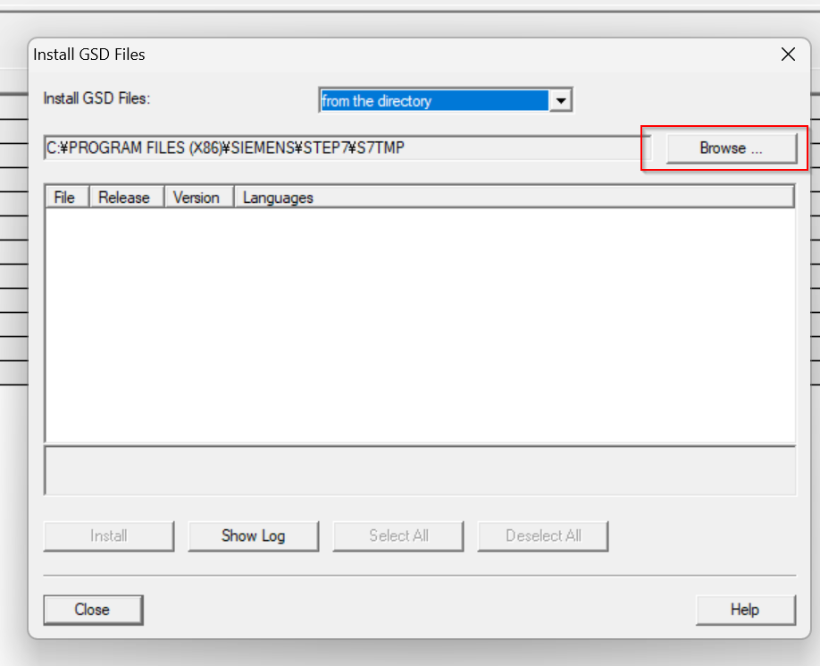
The GSD Install screen appears and click Browse.
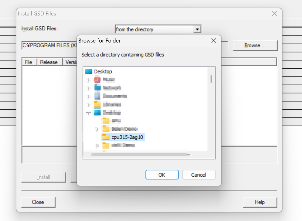
Select the Folder where the CPU 315-2 DP GSD File is stored and proceed with Ok.
we will be able to recognize the GSD File in the Folder.
I don’t know German, etc., so choose English and go to >Install to add the GSD File.
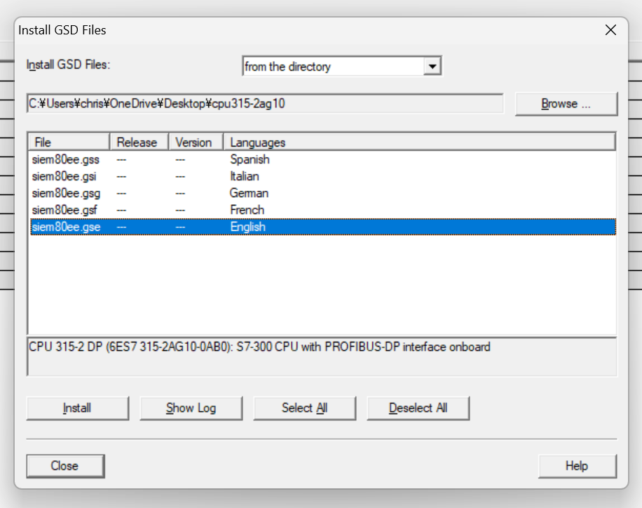
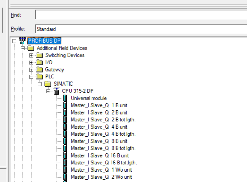
Done!You can see the Siemens CPU from PROFIBUS DP>Additional Field Devices>PLC>SIMATIC>CPU 315-2 DP.
Open another project, set the CPU’s DP Port to Master Mode, and add the CPU 315-2 DP to the DP Network.
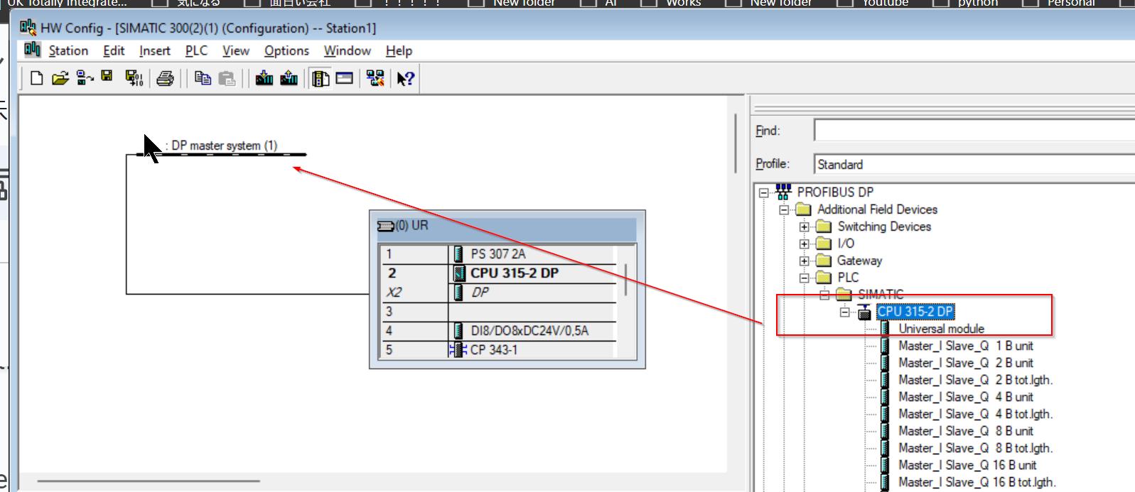
Proceed with Ok.
Done!CPU 315-2 DP has been added.
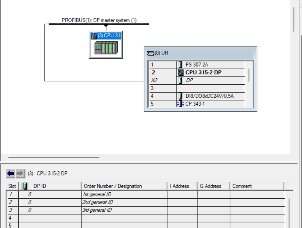
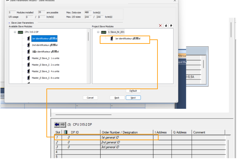
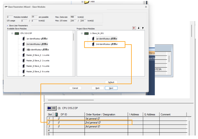
When I selected CPU 315-2 DP, there were Slots 1, 2, and 3 on Default. So there are at least 3 Slots to run CPU 315-2 DP as Profibus Slave.
It is 1st general ID, 2nd general ID, and 3rd general ID.
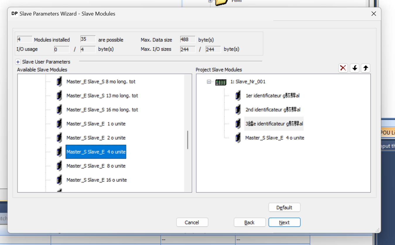
Add Slots1
Return to the DP Configuration Tool and Drop Slot1 to 1er identificatuer gxxx.
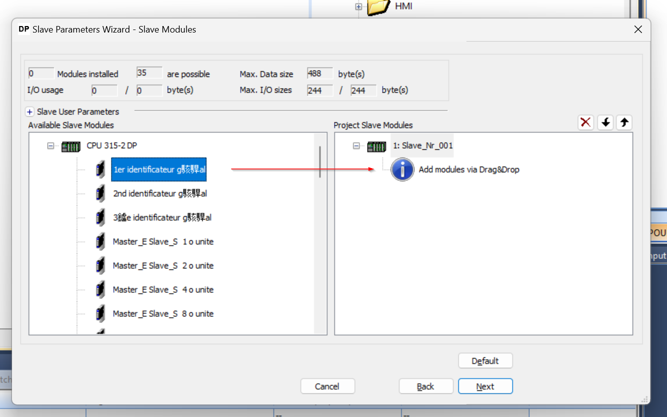
Done!
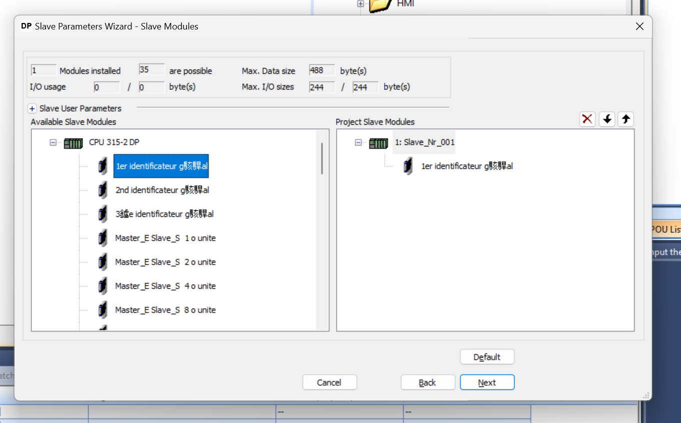
1er identificatuer gxxx in Slot 1 corresponds to 1st General ID.
Add Slots2
Drop Slot2 to 2nd identificatuer gxxx.
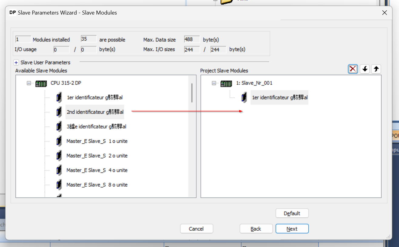
Done!
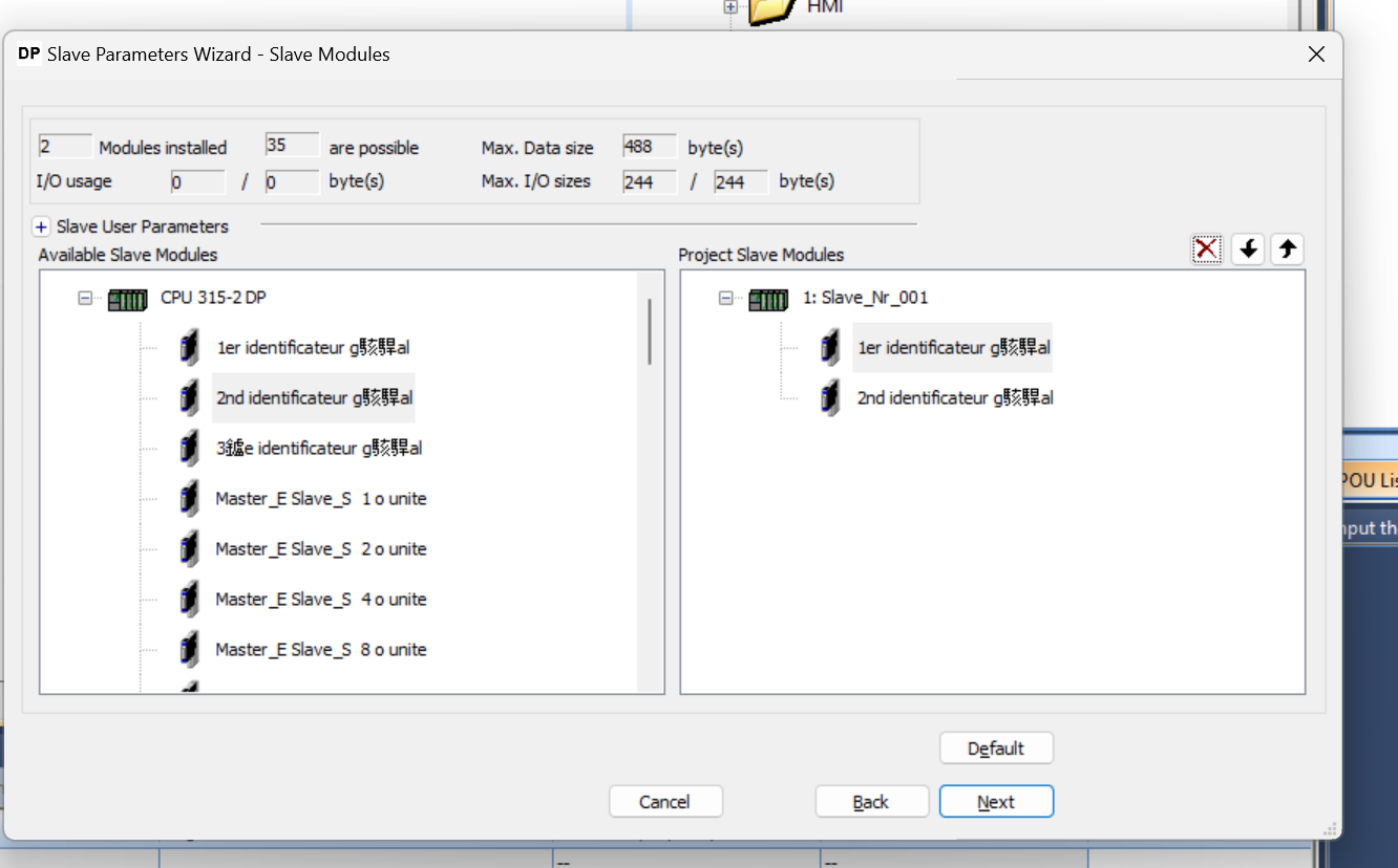
2nd identificatuer gxxx in Slot 2 corresponds to 2nd General ID.
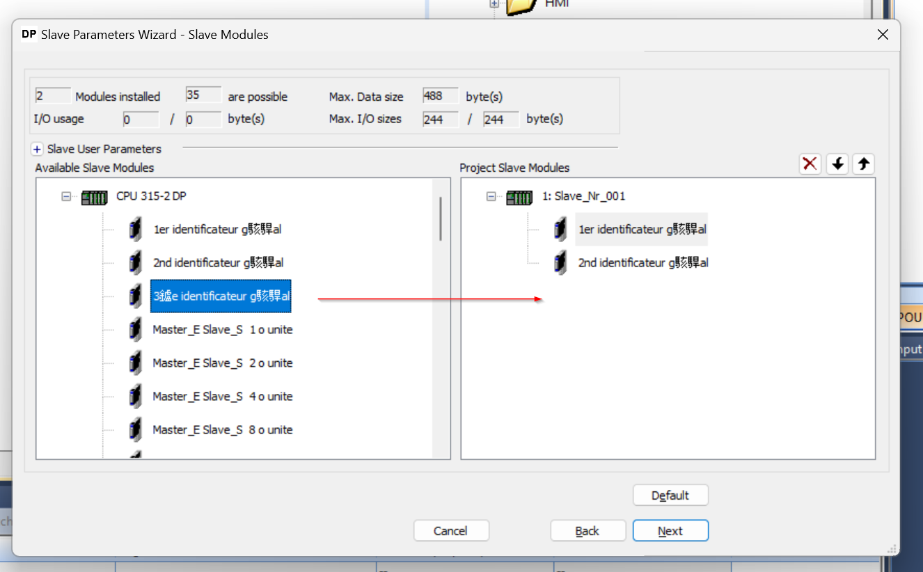
Add Slots3
Drop Slot3 to 3rd identificatuer gxxx.
Done!
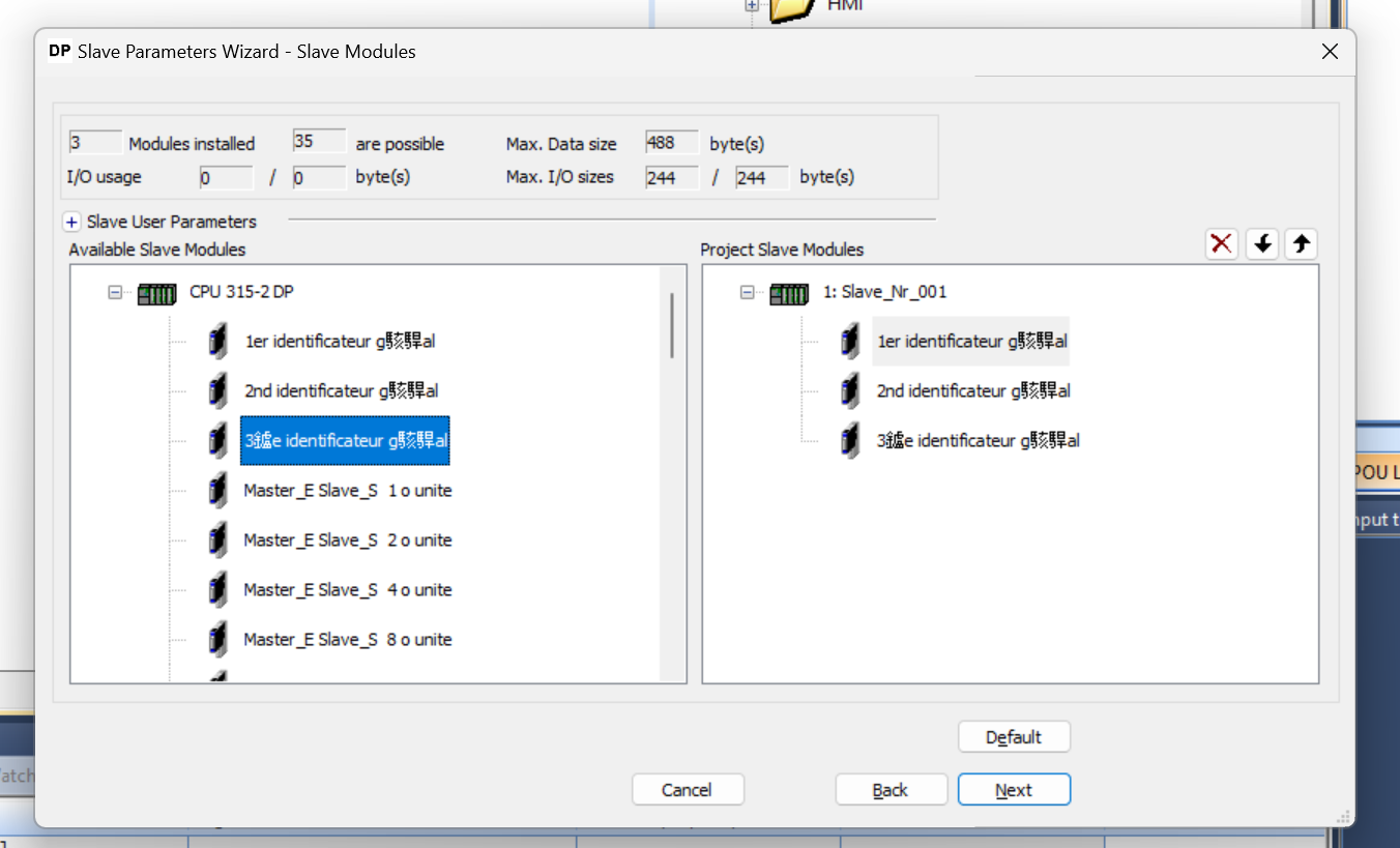
The 3rd identificatuer gxxx in Slot 3 corresponds to the 3rd General ID.
Add Slots4
Slot 4 defines a 4 Bytes output Slot, so let’s drop Master_S_Slave_E 4 o units.
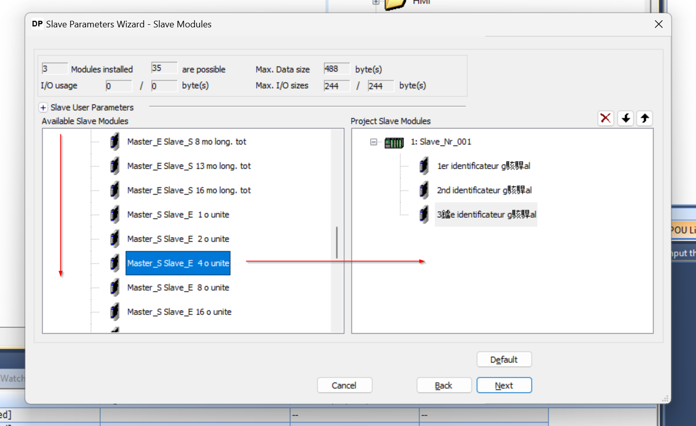
Done!
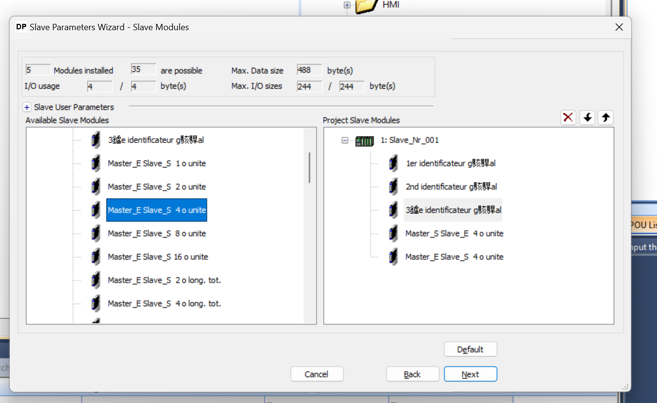
Add Slots5
Slot 5 defines a 4 Bytes input Slot, so let’s drop Master_S_Slave_S 4 o units.
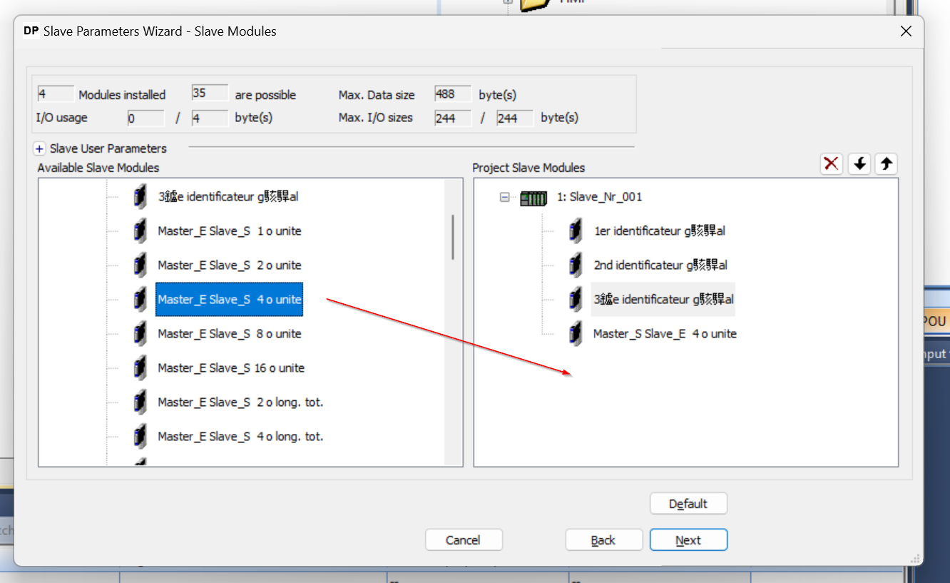
Done!Slot setup is now complete, so press the Next button to proceed.
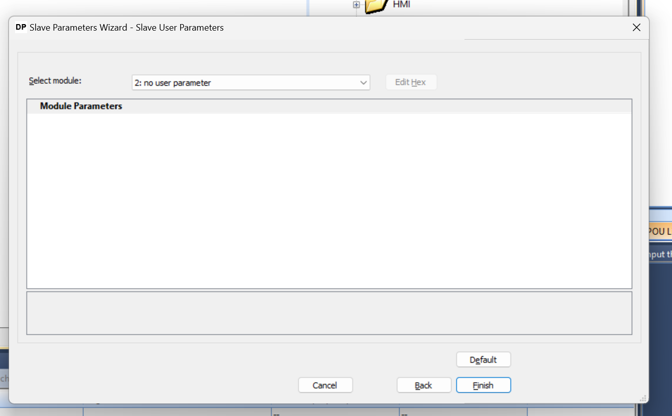
Slave User Parameters
The Slave Parameters screen is displayed, and there are no particular items that can be set, so use Finish to complete the settings.
Finally
Done!Now we can build the CPU 315-2 DP Profibus Slave Station.
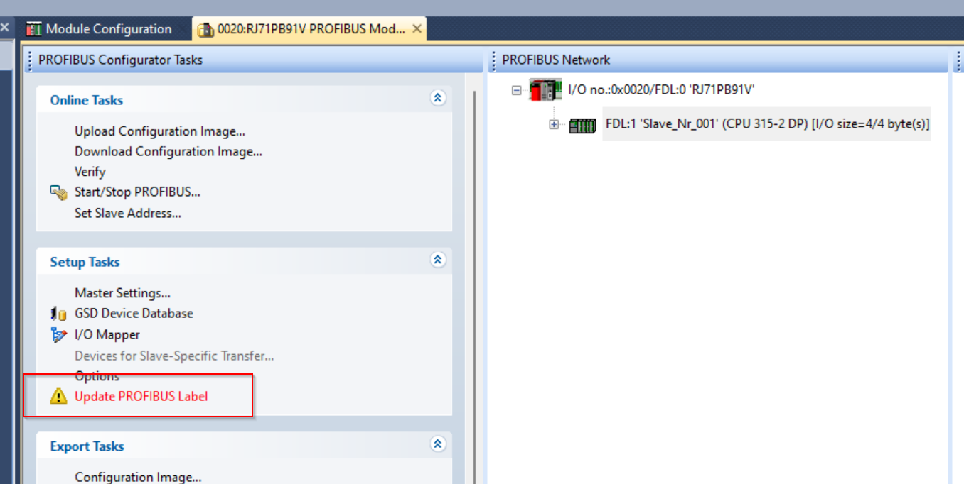
Update PROFIBUS Label
Like the Profinet IO Controller RJ71PN91 module, the RJ71PB91V can automatically generate Slave Station data in the form of a Global Label, which GXWORKS3 automatically builds in the Tool.
Click on Setup Task>Update PROFIBUS Label.
Note that if the “Update PROFIBUS Label” is red, it means that the Global Label of the Profibus Station needs to be updated.
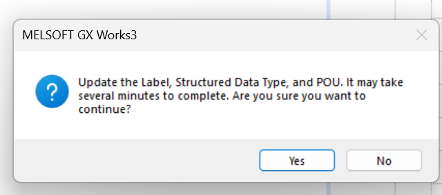
Proceed with Yes.
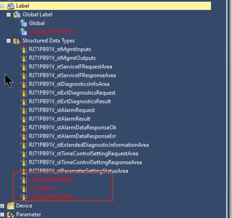
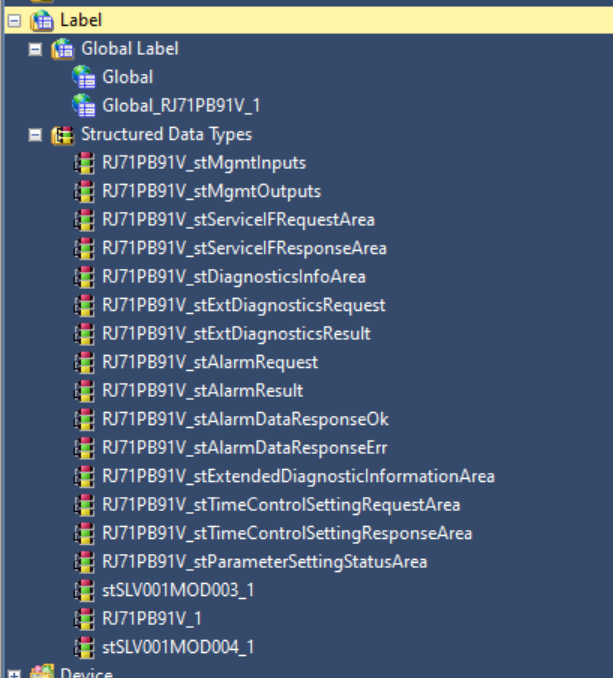
Done!The Global Label and structure have also been updated.
Compile all
Compile your project with Convert>Rebuild All.
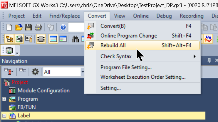
OK to proceed.
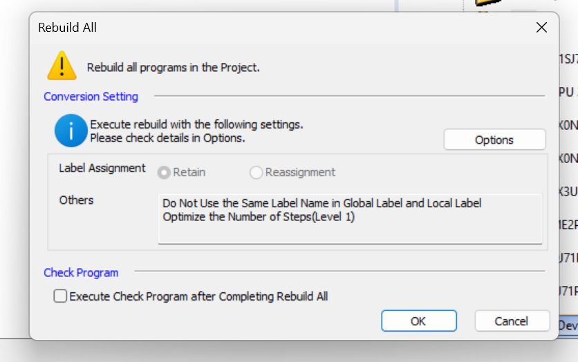
Done!All Global Labels and structures were also compiled without error.
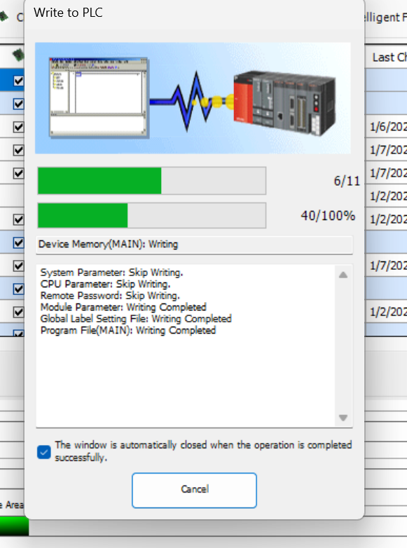
Write to PLC
Click Write to PLC to download the project to the CPU.
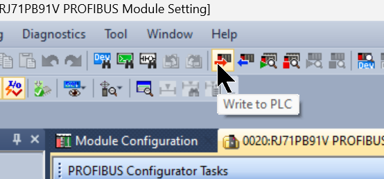
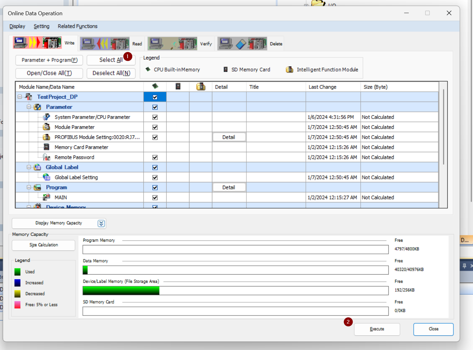
The Project Download screen appears.
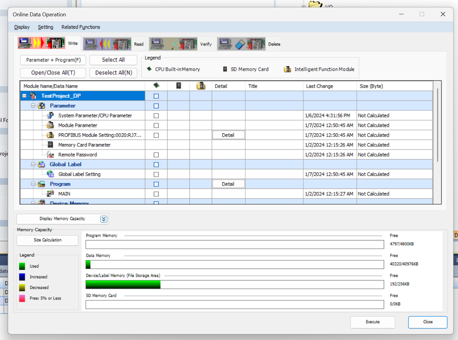
Select all Download Options under “Select All” and proceed with Execute.
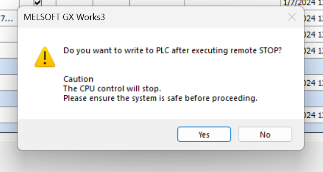
Proceed with Yes.
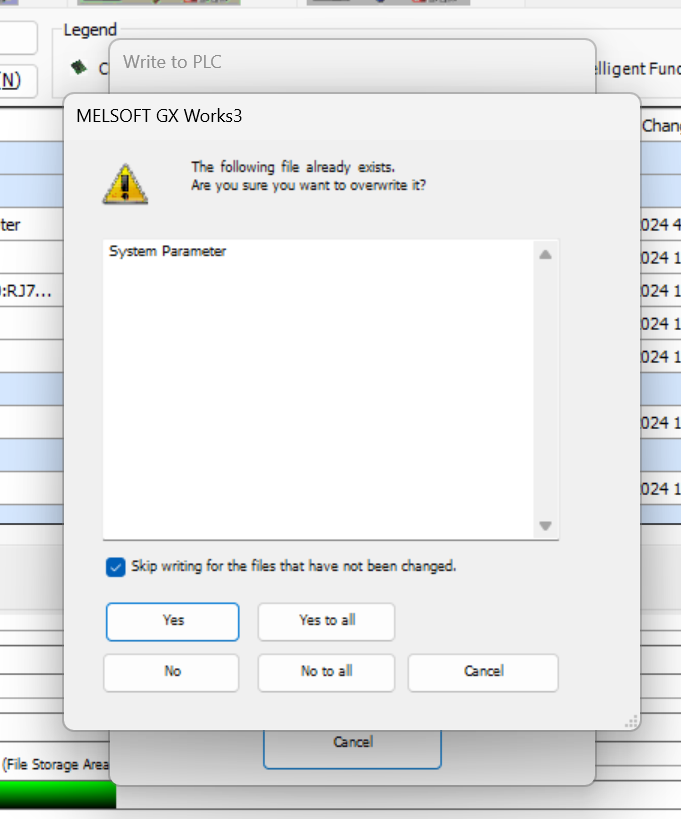
Proceed with Yes to All to overwrite the existing project on the CPU.
Just a second..
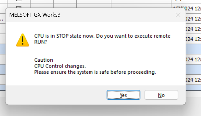
Press Yes to switch the CPU to RUN Mode.
Reset Power
If an error occurs in the CPU, reset the power.
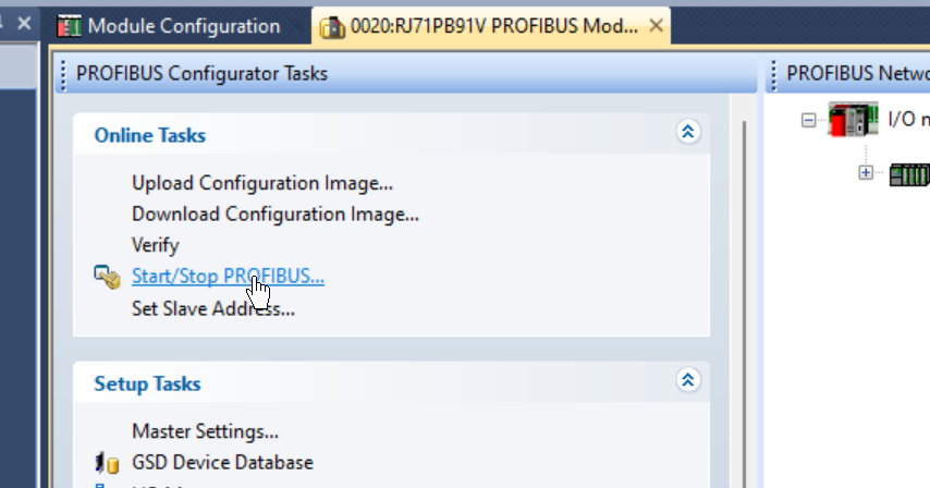
Start PROFIBUS
Implementation 1 we will introduce the operation of starting PROFIBUS from the PROFIBUS Configuration Tools without a program.
Online Tasks>Start/Stop PROFIBUS to start PROFIBUS Master.
Result
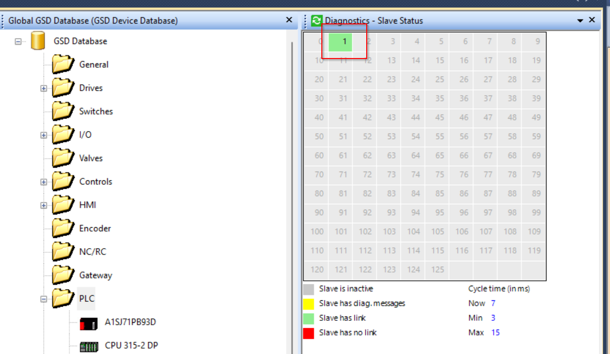
First, check the Profibus Slave status at Diagnostics>Slave Status.
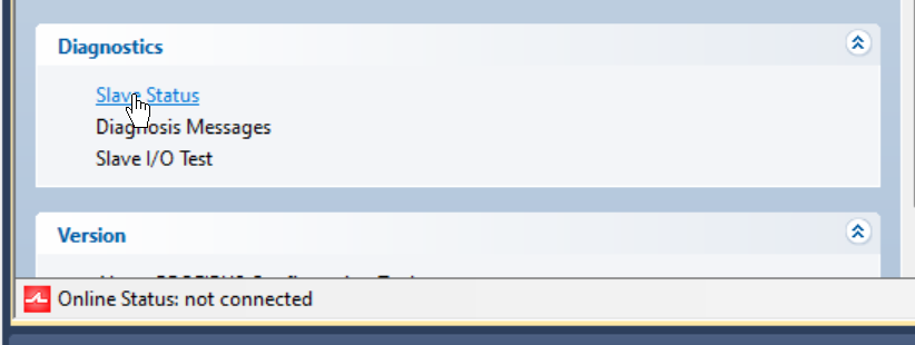
The number 1 is now green and communication has been established between the RJ71PB91V and the CPU 315-2 DP.
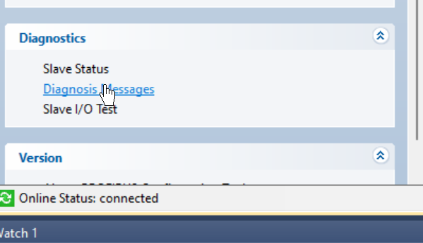
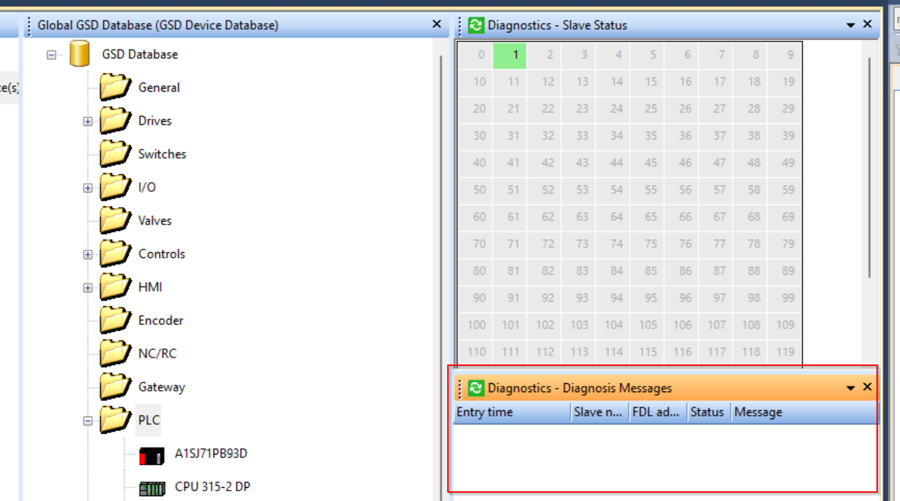
Next, open Diagnostics>Diagnosis Messages.
The diagnostic messages of Profibus Slave can be seen in the screen with the red frame.
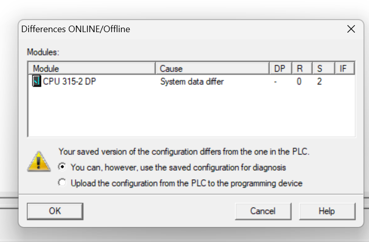
Now click the Online button to check the communication status from Step 7 Classic.
OK to proceed.
Just a second..
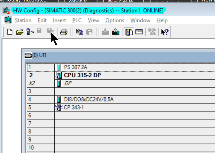
Done!There is currently no red error ICON in Hardware Configuration, indicating that it is communicating normally with the RJ71PB91V.
Implemenation2
In the next section, Implementation, we will create the actual program.
Siemens Side
Add OB
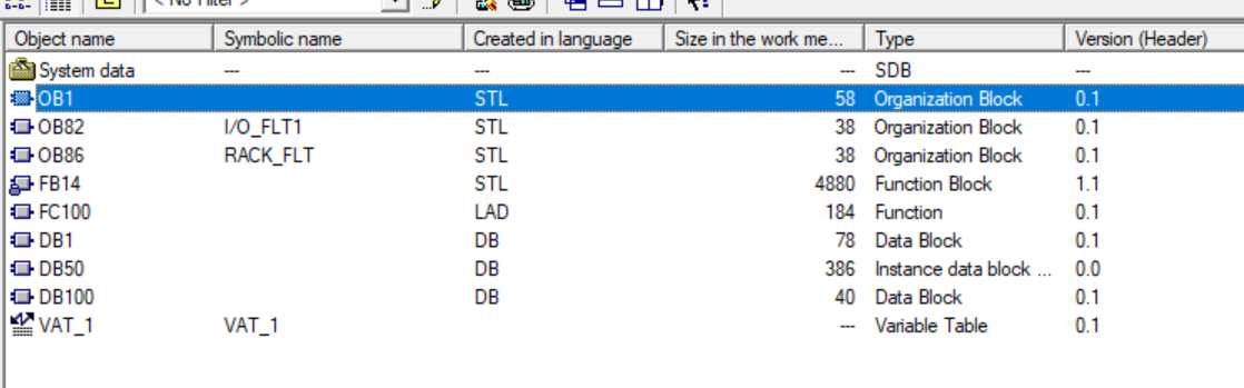
Go to Step 7 Classic>Program Blocks>right click>Insert New Object>Add Organization Block.
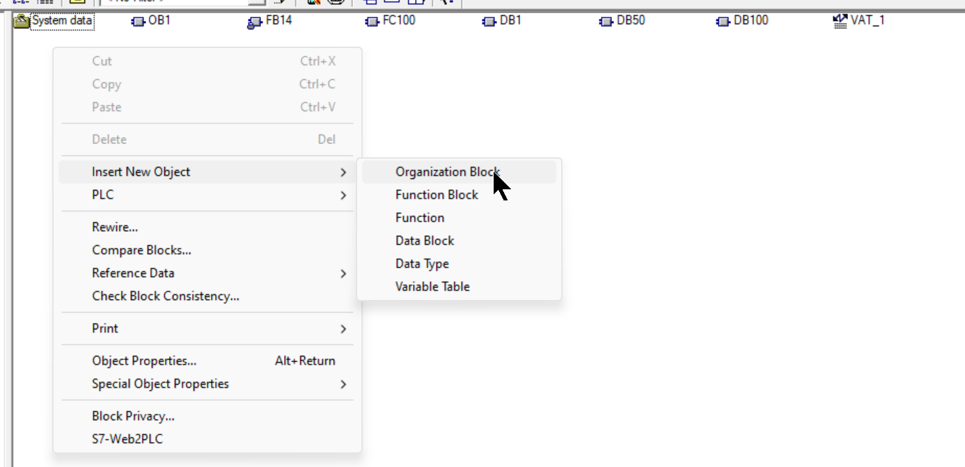
This is the Organization Block settings screen.
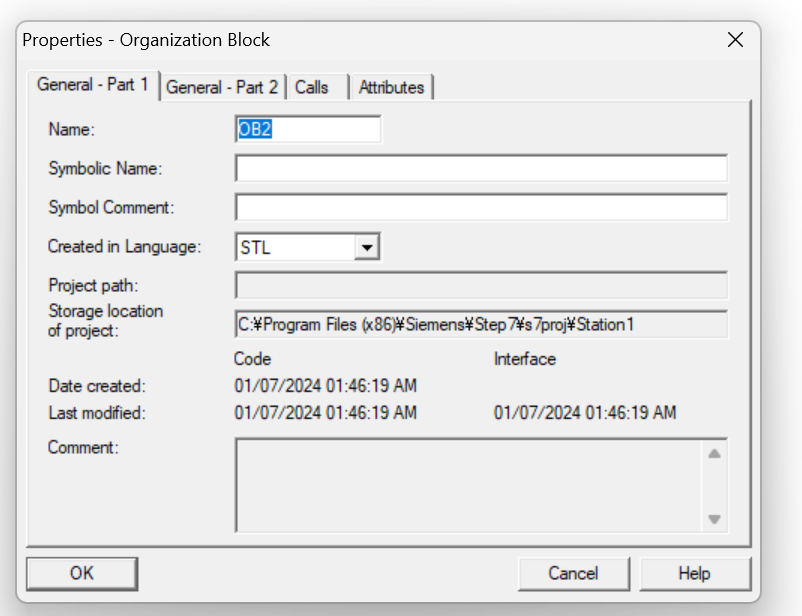
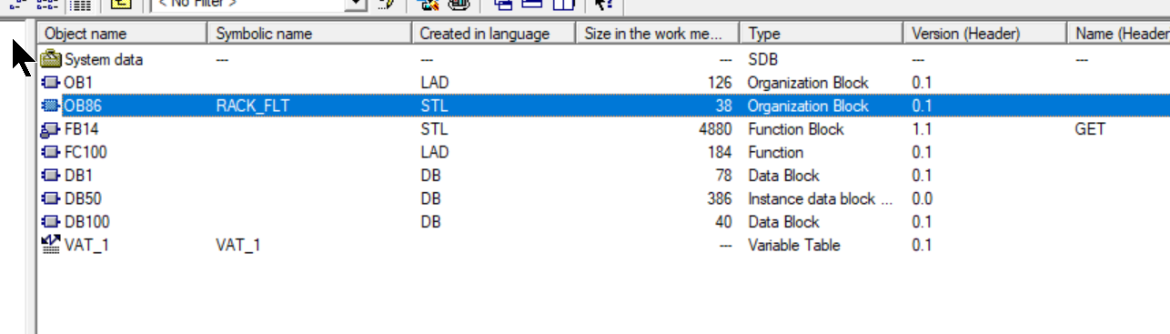
Enter OB86 in the Name Field and add the error handling OB for OB86.
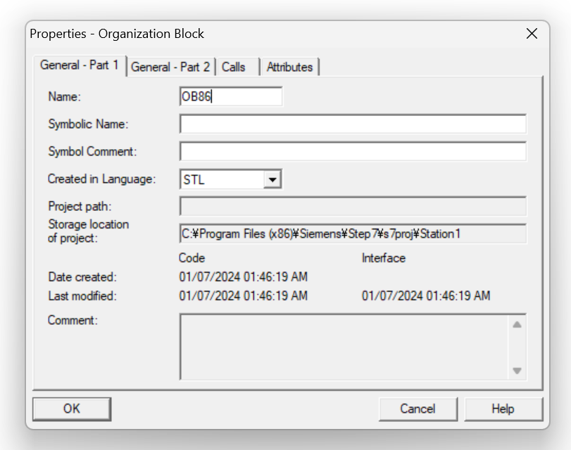
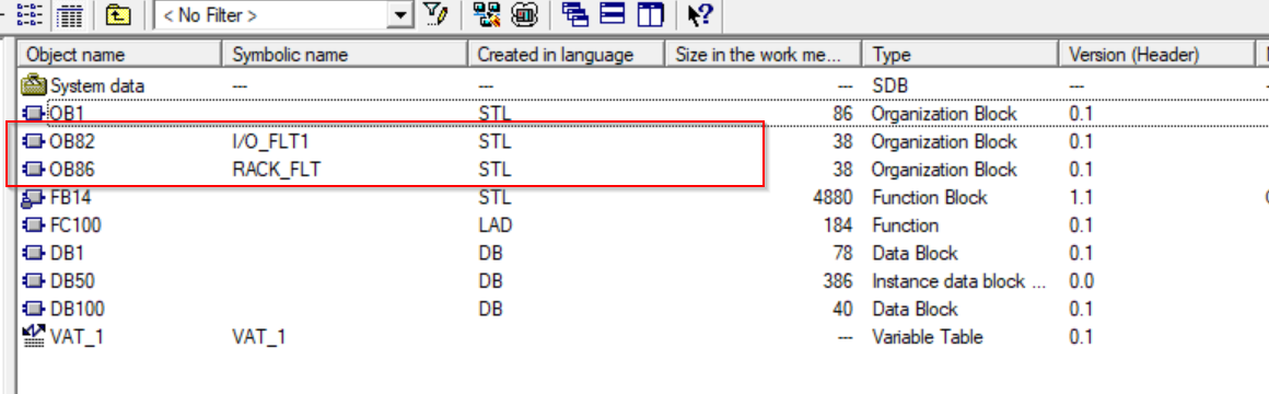
Done!By adding OB86, the CPU does not go into Stop Mode when a Rack Fault occurs.
Let’s also add an OB82 IO Fault using the same operation as before.
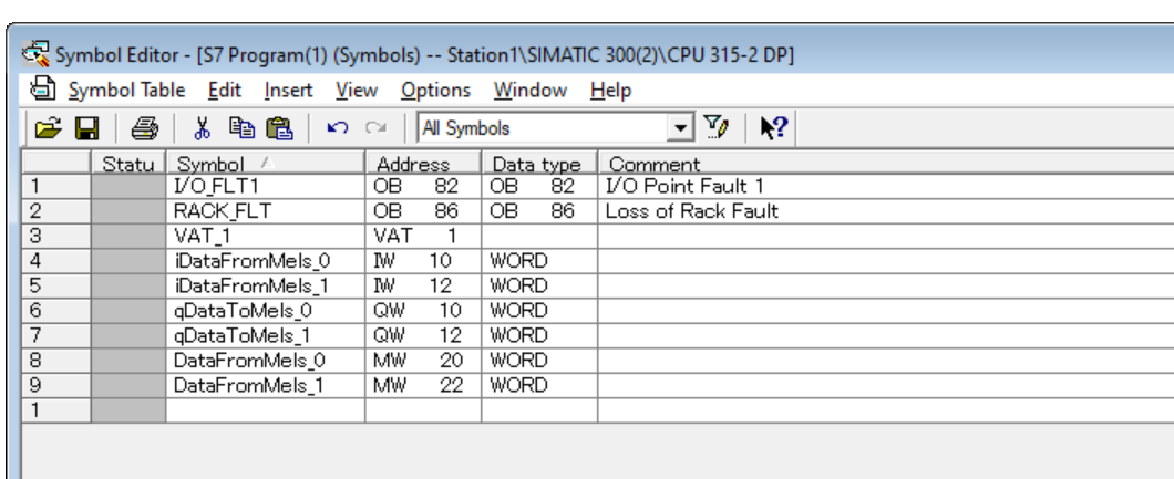
Symbols
Next, open the Symbols Table and define variables for input and output data.
This is the Symbo Editor.
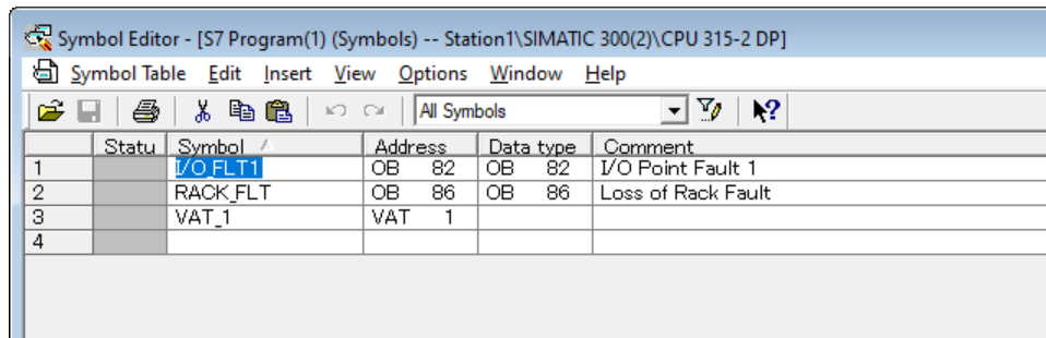
IW10 IW12 and QW10 QW12 are declared.
IW10=Input data Offset 10, 16BIt.
QW10=Input data Offset 10, 16BIt.
Program
Next, let’s create a program to send data from the CPU 315-2 DP to the RJ71PB91V.
Double click on OB1.
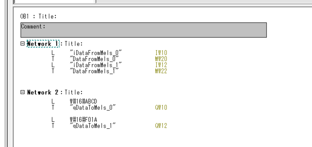
Add the STL program shown below.
- Network1
- Transfers IW10 (data received from RJ71PB91V) to MW20.
- Transfers IW12 (data received from RJ71PB91V) to MW22.
- Network2
- Send hexadecimal data ABCD to QW10 (RJ71PB91V).
- Send hexadecimal data F01A to QW12 (RJ71PB91V).
Download
Next, select S7 Station and click the Download button to download the project to the CPU.
Mels Side
Profibus Network Setting
Configure the Profibus Network settings.
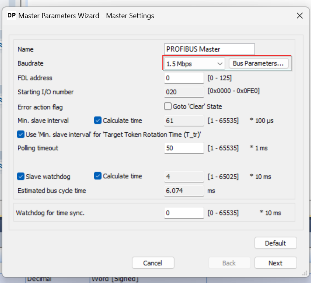
Master Setting
Click on RJ71PB91V Profibus Master and change the parameters of the Profibus Master.
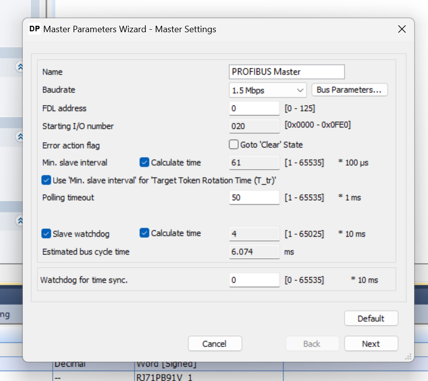
Depending on the case, change the Baudrate to the communication speed of the PROFIBUS-DP network. All Slaves must match this Baudrate. If all is well, proceed with Next.
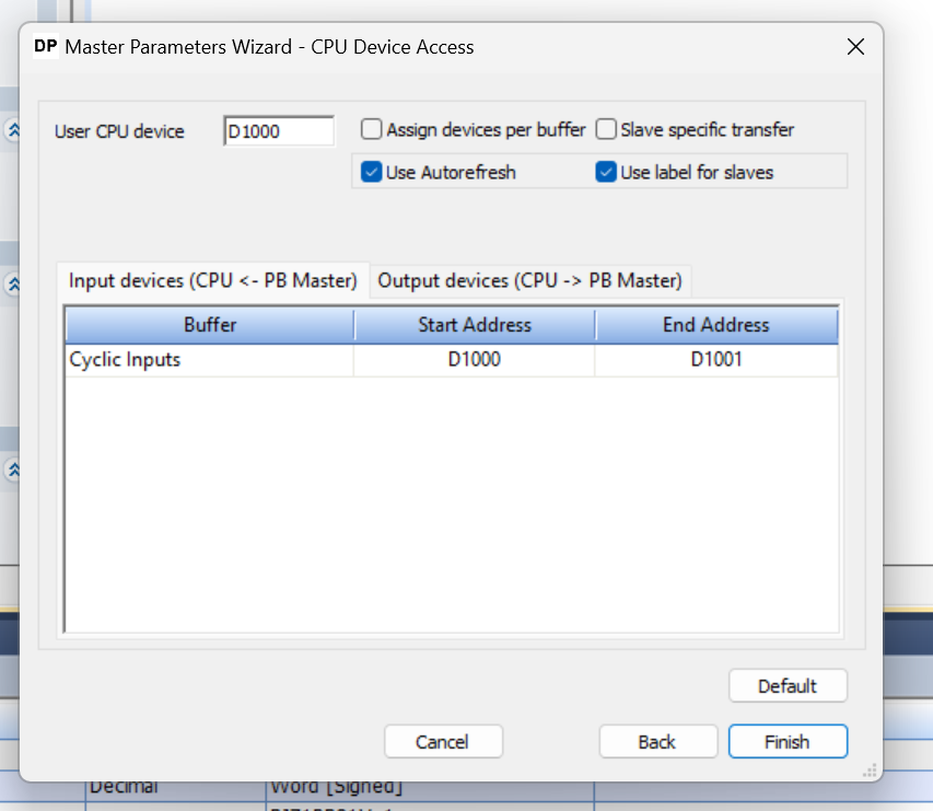
CPU Device Access
The CPU Device Acess screen allows you to set the CPU memory address for PROFIBUS network transmit and receive data. In the figure below, User CPU device D1000 is set, so the PROFIBUS network transmit/receive data will start from D1000.
Slave Settings
Since the Byte Order of Siemens CPU and Mitsubishi CPU are different, it is necessary to SWAP the Byte Order of either data.
If the corresponding slave needs to be swapped, check the “Swap I/O Bytes In Master” checkbox.

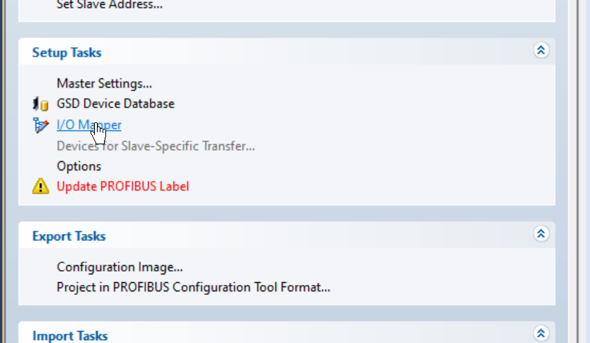
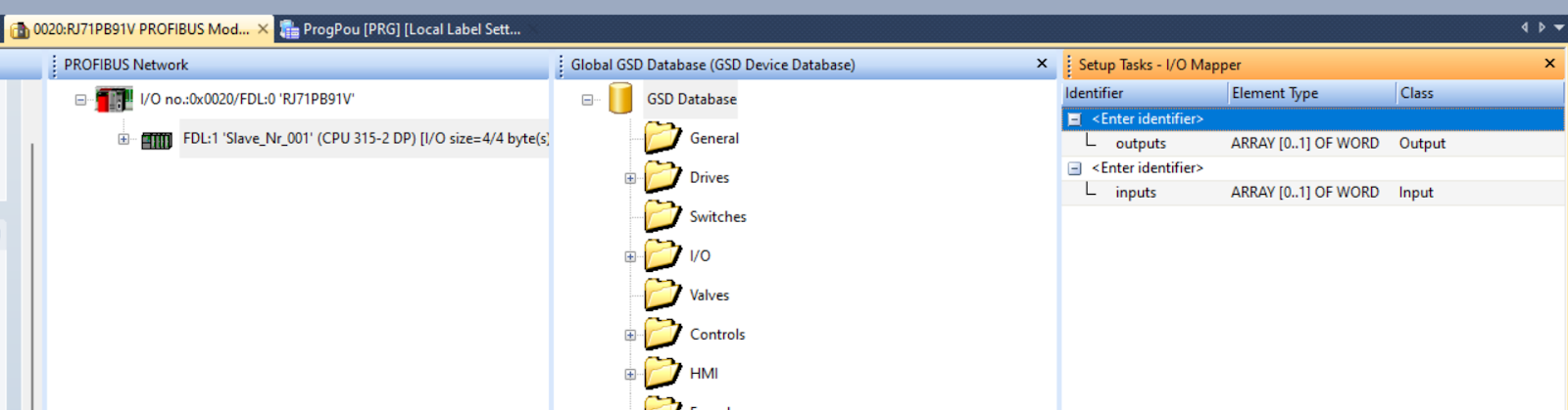
I/O Mapper
In Setup Tasks, there is a tool called I/O Mapper that allows you to check the actual data memory locations of the PROFIBUS network.
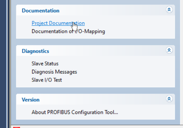
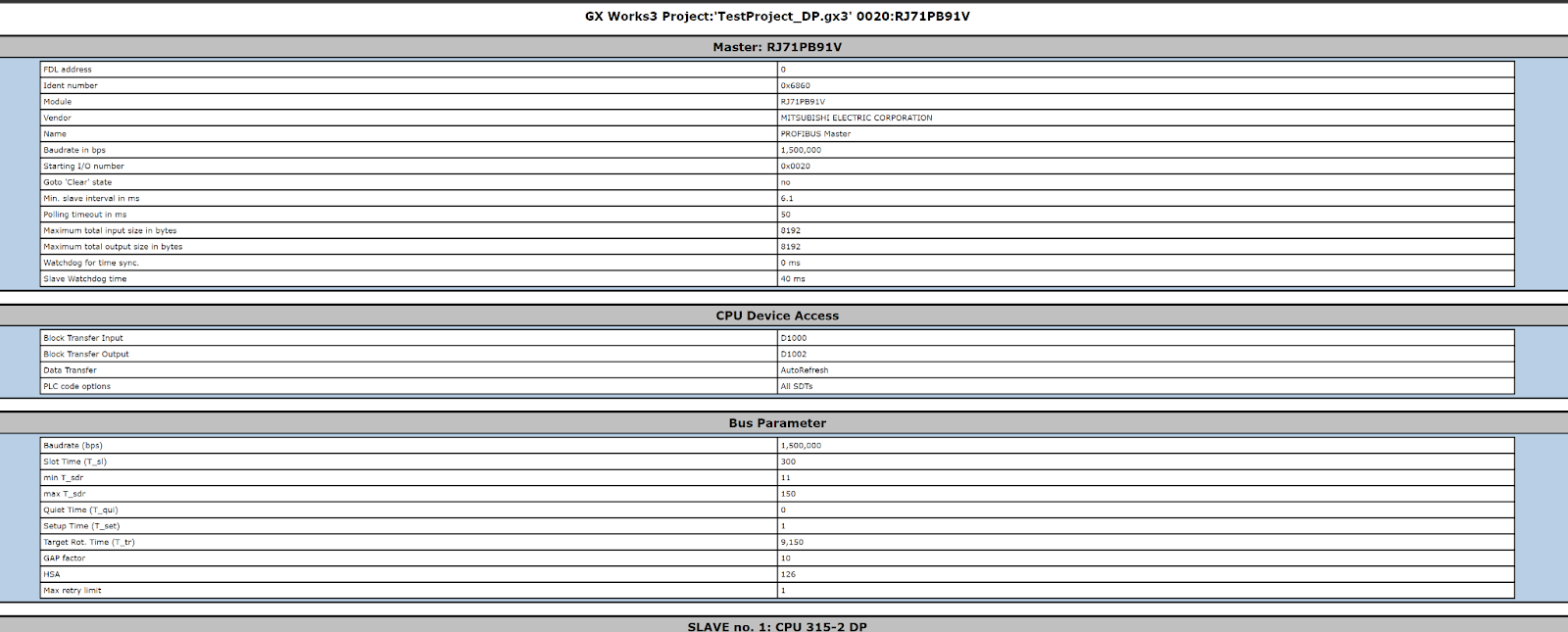
Project Documentation
You can check the IO Mapping of the Profibus network you have built with RJ71PB91V under Documentation>Project Documentation.
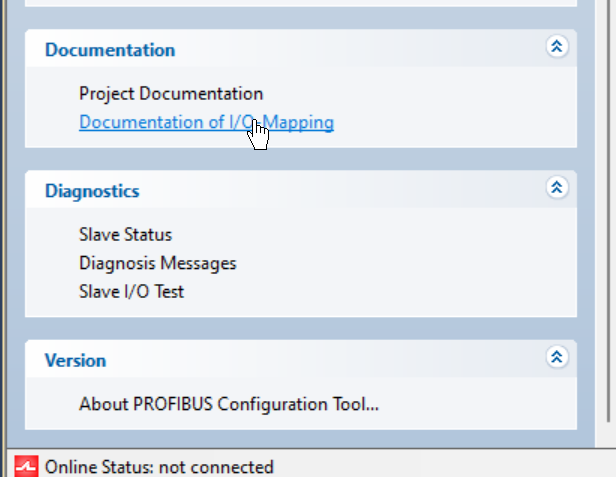
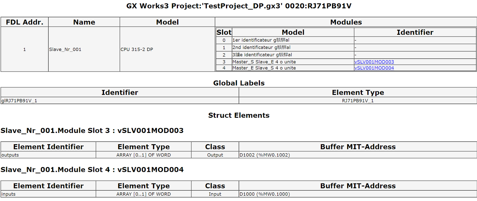
Documentation of I/O Mapping
You can check the IO Mapping of the Profibus network you have built with RJ71PB91V Exchange data under Documentation>Project Documentation.
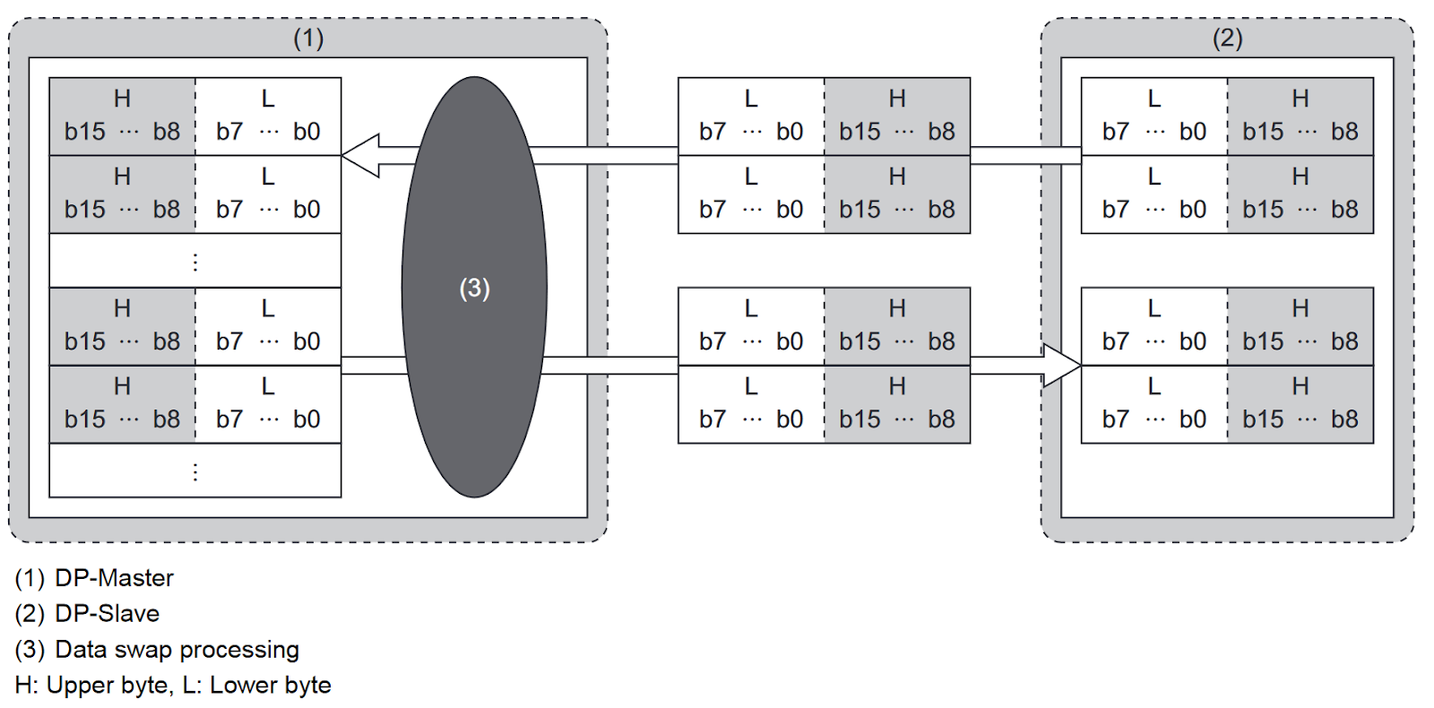
Byte Swap
Each Device can SWAP the automatic Byte Order depending on the application.
For example, Siemens CPU is different from IQ-R Byte Order, so please put a Checkbox for Swap I/O Bytes in Master.
This function allows the upper and lower bytes of the exchanged data to be swapped in word units when sending and receiving I/O data. It is used when the word configuration of I/O data differs between DP master and DP slave (upper byte and lower byte are reversed) (without programming).
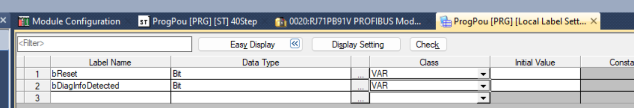
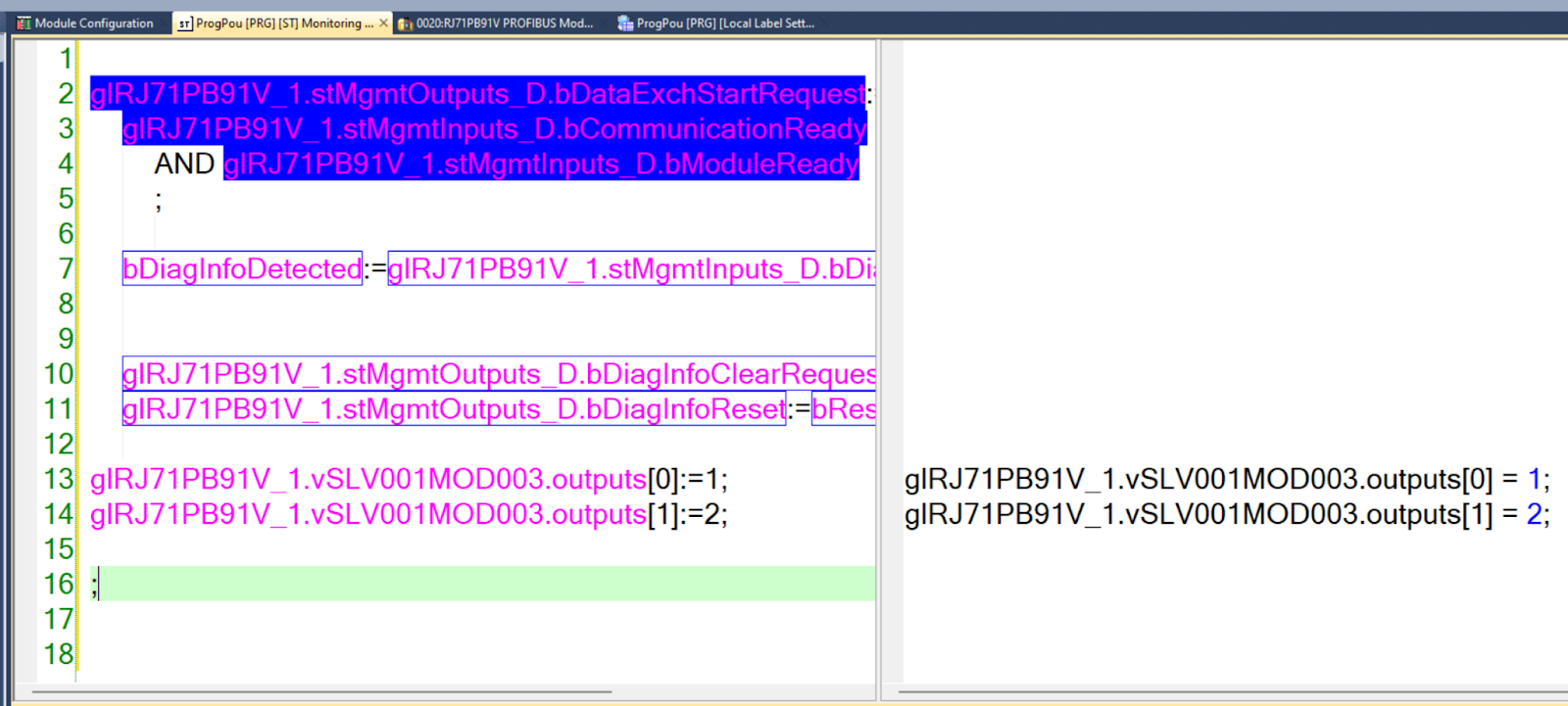
Program
Finally, let’s create a communication program between the RJ71PB91V and the Siemens CPU 315-2 DP.
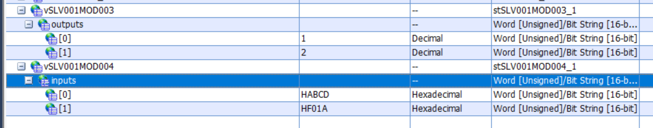
| glRJ71PB91V_1.stMgmtOutputs_D.bDataExchStartRequest:= glRJ71PB91V_1.stMgmtInputs_D.bCommunicationReady AND glRJ71PB91V_1.stMgmtInputs_D.bModuleReady ; bDiagInfoDetected:=glRJ71PB91V_1.stMgmtInputs_D.bDiagInfoDetected; glRJ71PB91V_1.stMgmtOutputs_D.bDiagInfoClearRequest:=bReset; glRJ71PB91V_1.stMgmtOutputs_D.bDiagInfoReset:=bReset; glRJ71PB91V_1.vSLV001MOD003.outputs[0]:=1; glRJ71PB91V_1.vSLV001MOD003.outputs[1]:=2; ; |
Result
Done!RJ71PB91V is programmed to start Profibus and communicate with CPU 315-2 DP. RJ71PB91V has programmed Profibus and is communicating with CPU 315-2 DP.
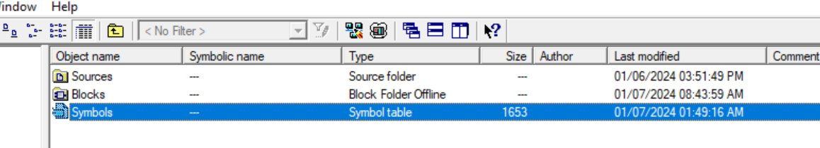
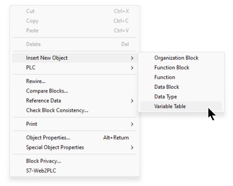
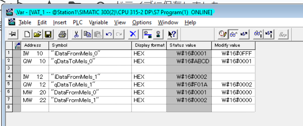
Next, to check the communication data on the Step 7 Classic side, create a variable Table with Insert New Object>Variable Table.
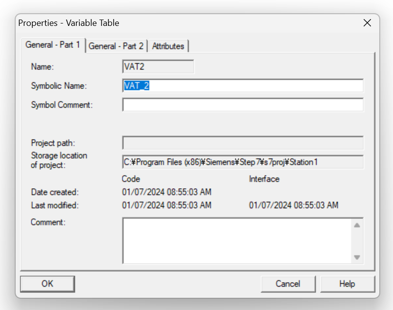
Enter the variable Table name in the Field of Symoblic Name.
You can enter the variable you just defined into the Table and click on the glasses ICON to see the current location of the variable.
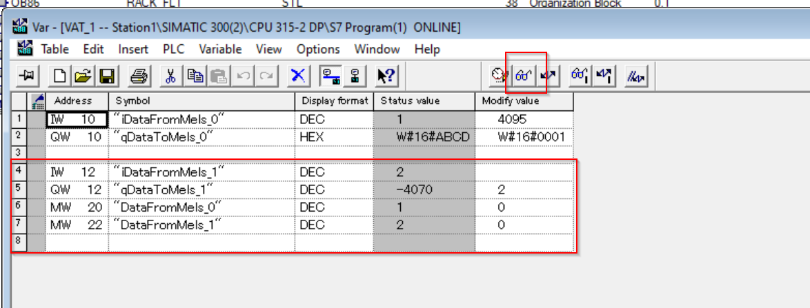
If you want to change the display format of a variable, right-click on it and set another display format such as Hexadecimal.
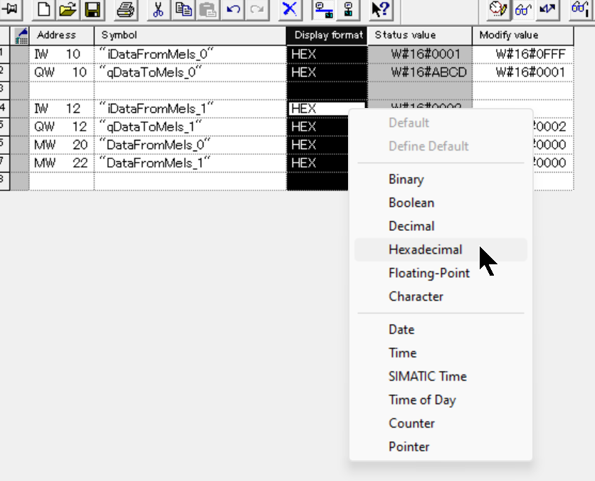
Done!
In this video, you can actually check the communication status of Profibus with RJ71PB91V and CPU 315-2 DP.