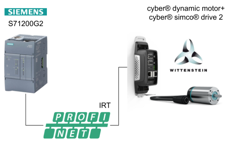
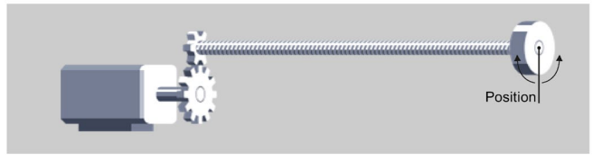
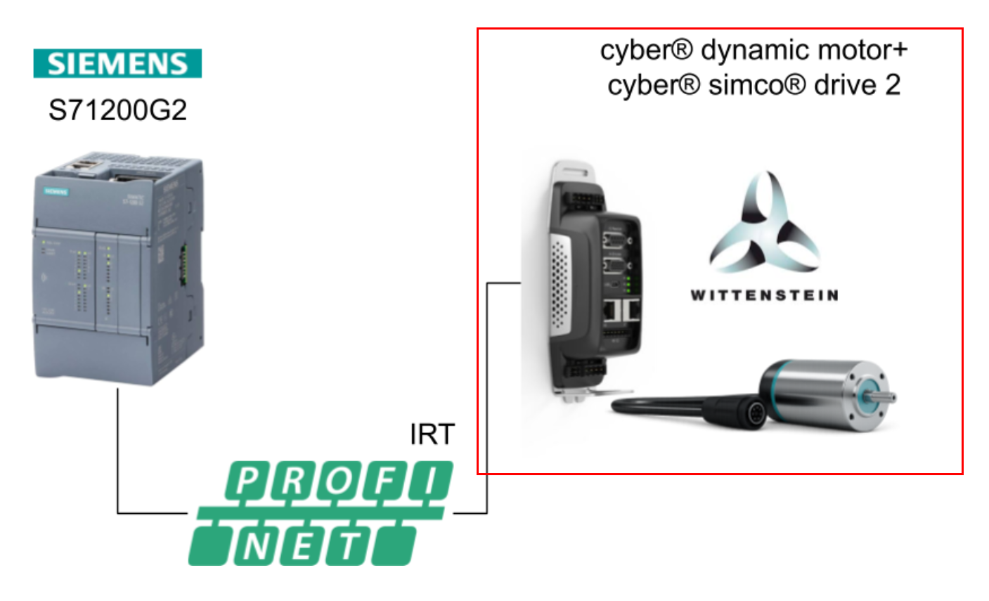
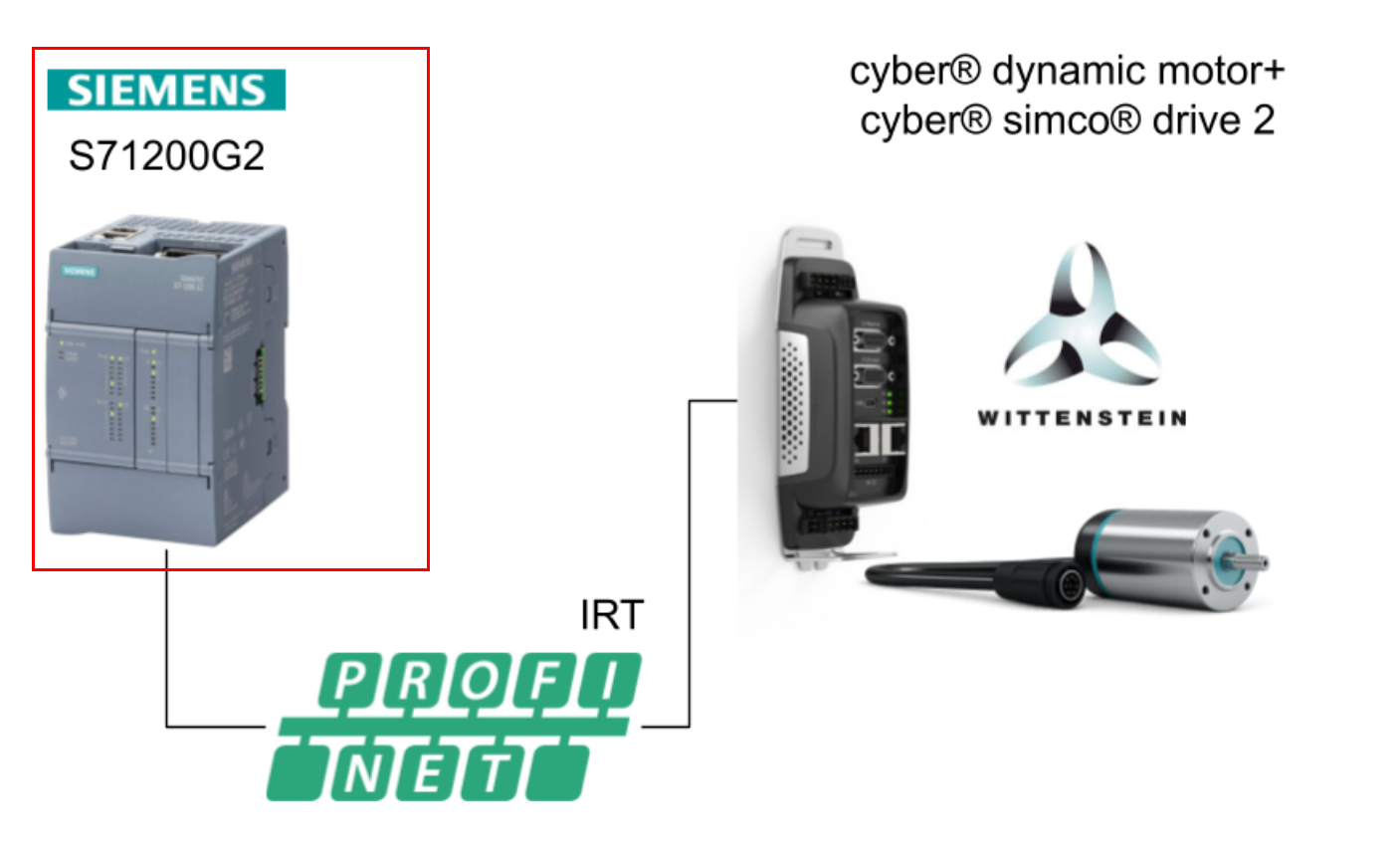
In this article, we will try to build a PROFINET IRT with a SIEMENS S7-1200 G2 × WITTENSTEIN servo. We have summarized the procedure of building with the actual machine, from setting up the servo drive (simco® drive 2) to programming with TIA Portal. It also explains the real-time nature of the control and points to note. Recommended for those who want to actually run the machine!
Come on, let’s enjoy FA’s.
Foreword
Thank you from the bottom of my heart for visiting my technical blog and YouTube channel.
We are currently running the “Takahashi Chris” radio show with Full-san (full@桜 八重 (@fulhause) / X) which I deliver every Wednesday night.
Sharing, not hoarding, technical knowledge
We publish technical information related to factory production technology and control systems for free, through blogs and videos.
With the belief that “knowledge should be accessible to everyone,” we share practical know-how and real-world troubleshooting cases from our own field experience.
The reason we keep it all free is simple: to help reduce the number of people who struggle because they simply didn’t know.
If you’ve ever thought:
- “Will this PLC and device combination actually work?”
- “I’m having trouble with EtherCAT communication—can someone test it?”
- “I want to try this remote I/O, but we don’t have the testing environment in-house…”
Feel free to reach out!If lending equipment or sharing your configuration is possible, we’re happy to verify it and share the results through articles and videos.
(We can keep company/product names anonymous if requested.)
How can you support us?
Currently, our activities are nearly all unpaid, but creating articles and videos takes time and a proper testing environment.If you’d like to support us in continuing and expanding this content, your kind help would mean a lot.
Membership (Support our radio show)
This support plan is designed to enhance radio with Mr Full.
https://note.com/fulhause/membership/join
Amazon Gift List (equipment & books for content production)
Lists equipment and books required for content creation.
https://www.amazon.co.jp/hz/wishlist/ls/H7W3RRD7C5QG?ref_=wl_share
Patreon (Support articles & video creation)
Your small monthly support will help to improve the environment for writing and verifying articles.
https://www.patreon.com/user?u=84249391
Paypal
A little help goes a long way.
https://paypal.me/soup01threes?country.x=JP&locale.x=ja_JP
Just trying to share things that could’ve helped someone—if only they’d known.
Your support helps make knowledge sharing more open and sustainable.
Thank you for being with us.
soup01threes*gmail.com
Technical knowledge shouldn’t be kept to ourselves.

Reference Link
http://soup01.com/en/category/siemens-en/s7%e2%80%901200-g2-en/
Motion control from TIA Portal
Create a project, configure the technology object, and download the configuration to the CPU using the TIA Portal. Then download to the CPU. Motion control functions are handled by the CPU.
TIA Portal provides functions such as commissioning, optimization and diagnostics.
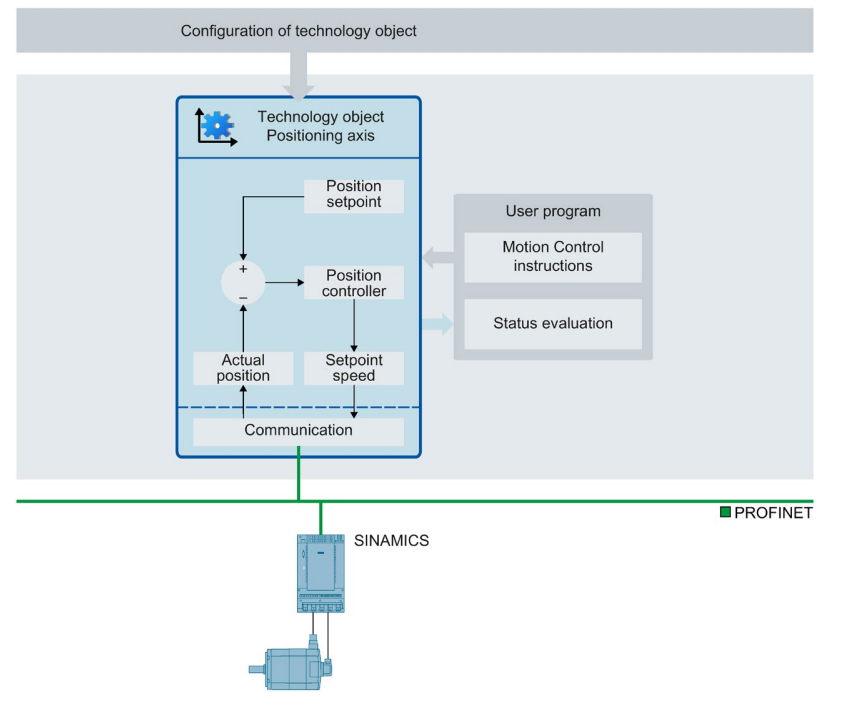
The following figure outlines the user interface and the integration of motion control into the S7-1500 CPU. The following is a brief description of the concept.
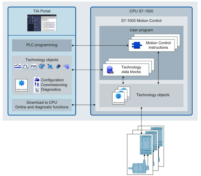
Feature
The TIA Portal supports the planning and commissioning of motion control functions:
- Hardware Integration and Configuration
- Creation and configuration of technology objects
- Creation of user programs
- Download to CPU
- Commissioning of axes
- Drive optimization
- Diagnostics
Technology objects?
Technology objects represent the actual objects in the controller (e.g., drives). The user program’s motion control instructions call the functions of the Technology objects. Technology objects perform open-loop and closed-loop control of the real object’s motion and feed back status information (e.g., current position).
To summarize it briefly,
- The configuration of Technology objects represents the actual object characteristics.
- The configuration data is stored in the Technology data block.
The following technology objects are available for motion control
Speed axis technology object
The speed axis technology object (“TO_SpeedAxis”) is used to specify the speed of the drive. The axis motion is programmed with motion control instructions.
Positioning axis technology object
The Positioning Axis technology object (“TO_PositioningAxis”) is used to position the drive in closed-loop position control. Positioning jobs are issued to the axis with motion control instructions in the user program.
Synchronous axis technology object
The synchronous axis technology object (“TO_SynchronousAxis”) contains all the functionality of the positioning axis technology object. The axis can also be interconnected with a leading value so that it follows the position change of the preceding axis in a synchronous motion.
External encoder technology object
The external encoder technology object (“TO_ExternalEncoder”) detects the position and makes it available to the controller. The detected position can be evaluated by the user program.
Measuring input technology object
Measuring input technology object (“TO_MeasuringInput”) quickly and accurately detects the actual position and triggers events.
Output cam technology object
The Output cam technology object (“TO_OutputCam”) generates switching signals according to the position of an axis or external encoder. The switching signal can be evaluated in a user program or sent to a digital output.
Cam track technology object
The Cam track technology object (“TO_CamTrack”) generates a switching signal sequence according to the position of an axis or external encoder. In this process, up to 32 cams are superimposed and the switching signals are output as tracks. The switching signals can be evaluated in a user program or fed to a digital output.
Cam technology object (S7-1500T)
The Cam technology object (“TO_Cam”) defines the function f(x) by interpolation points and/or segments, and missing function ranges are interpolated.
Kinematic technology object (S7-1500T)
The Kinematic technology object (“TO_Kinematics”) is used to kinematically interconnect positioning axes. Once configured, the kinematics technology object interconnects the axes according to the configured kinematics type.
Technology data block
The properties of each object are set by the technology object and stored in the technology data block. The Technology data block contains all configuration data, settings, measured values, and status information for the technology object. The TIA Portal automatically creates the Technology data block when a technology object is created. User programs are used to access (read/write access) the data in the Technology data block.
Motion Control instructions
Motion Control instructions allow you to perform the functions you need in your technology objects. Motion Control instructions are available in the TIA Portal under “Instructions > Technology > Motion Control. Motion Control instructions are based on PLCopen, version 2.0.
User program
Motion control instructions and Technology data blocks represent the programming interface for Technology objects. Motion control instructions are used to transfer the motion control jobs of Technology objects in the user program.
The status of running jobs is tracked in the output parameters of the Motion Control instruction. use the Technology data block to access status information on Technology objects during execution and to change certain configuration parameters.
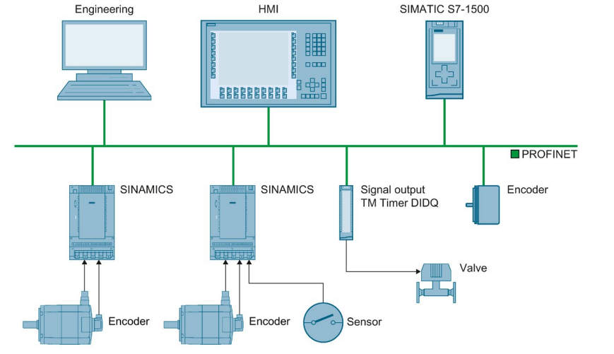
Drives and encoders
The drive ensures the movement of the axis. It is built into the hardware configuration. When a Motion Control job is run in the user program, the technology object takes over control of the drive and reading of the encoder values.
Drives with PROFIdrive functionality and encoders are connected via the PROFIdrive telegram. The following connections are possible
- PROFINET IO
- PROFIBUS DP
- Technology module (TM)
Drives with an analog setpoint interface are connected using an analog output (AQ) and an optional enable signal. Analog inputs and outputs are available via the corresponding I/O modules.
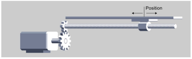
Axis types
Axes can be configured with a variety of axis types:
- Positioning and synchronization axes can be configured as rotary or linear axes.
- Velocity axes are always rotary axes. Depending on the execution of the mechanics, axes are implemented as linear or rotary axes:
- Linear Axis For a linear axis, the axis position is specified as a linear measure, such as millimeters (mm).
- Rotation axis For a rotation axis, the position of the axis is specified in angular units (°), etc.
PROFIdrive telegrams
PROFIdrive Telegram is used to transfer set and actual values, control and status words, and other parameters between the controller and the drive/encoder.
If a PROFIdrive telegram is used for the connection, the drive and encoder are treated and turned on according to the PROFIdrive profile.
- Control words STW1, STW2, status words ZSW1, ZSW2
- 32-bit speed set value (NSET), 32-bit measured speed value (NACT)
- Encoder actual measured value 1 (G1_XIST1, G1_XIST2)
- Dynamic servo control (DSC)2
- Velocity pre-control value
- Position difference (XERR)
- Kpc – Velocity pre-control value for closed loop position control
- Torque limit
Process response
OB for motion control
When you create a technology object, an OB is automatically created to handle the technology object. The motion control function of the technology object creates its own execution level and is called according to the motion control application cycle.
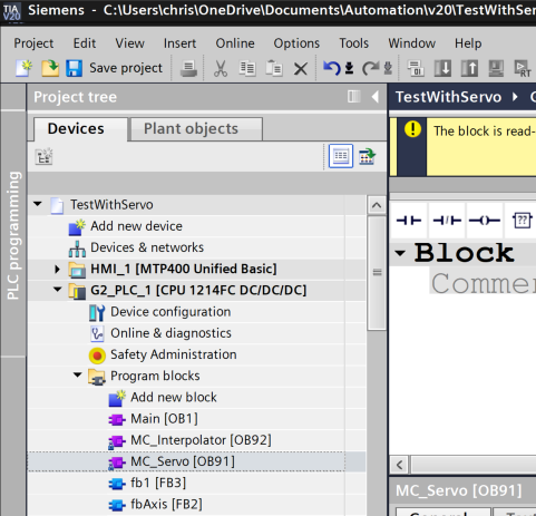
It creates the following blocks
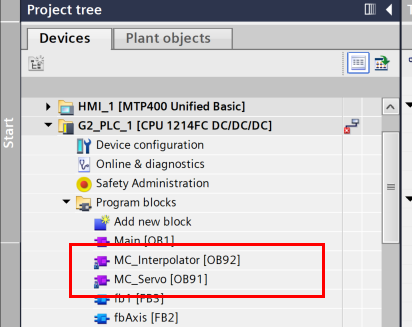
MC-Servo [OB91]
Position Controller Calculations
MC-Interpolator [OB92]
Motion control instruction evaluation, set point generation, and monitoring functions
Execution of two OBs
The OBs are know-how protected and the program code cannot be viewed or modified.
The frequency of the two OB blocks is always 1:1 and MC-Servo [OB91] always runs before MC-Interpolator [OB92]. Depending on the control quality and system load requirements, the application cycle and OB priority can be set.
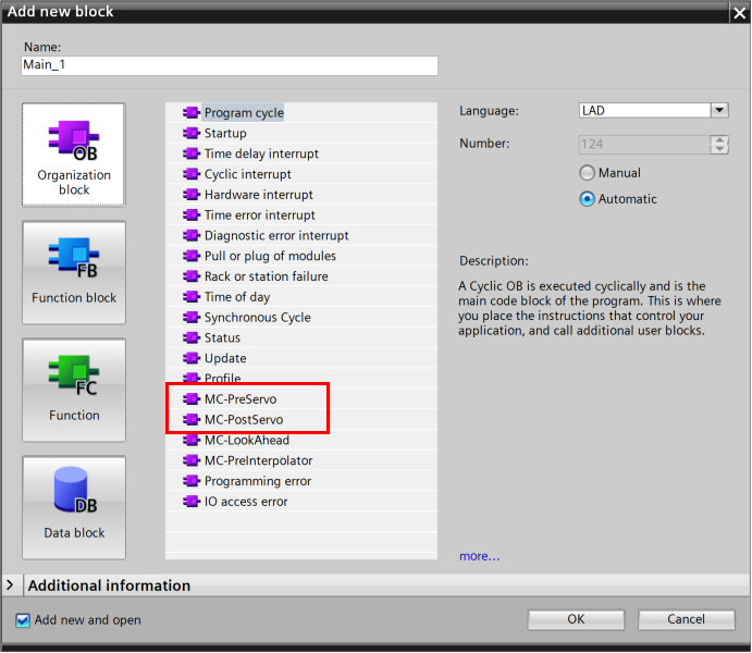
MC-PreServo [OB67] とMC-PostServo [OB95]
Additionally, OB blocks MC-PreServo [OB67] and MC-PostServo [OB95] can be created by the application.
OB MC-PreServo [OB67] and MC-PostServo [OB95] can be programmed and are called in the application cycle. This means that MC-PreServo [OB67] and MC-PostServo [OB95] OBs can be used for time-critical events such as consistent data processing, process motions that need to run synchronously with the application cycle, and the start of homing functions
application cycle
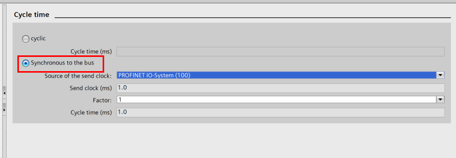
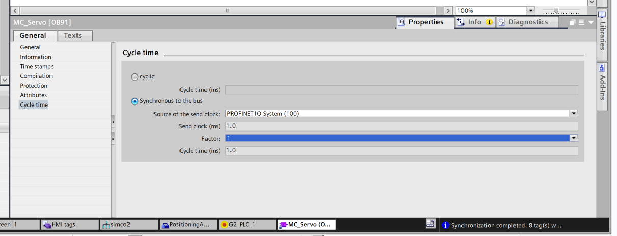
The application cycle in which MC-Servo [OB91] is invoked can be set in the OB properties under “General > Cycle Time:
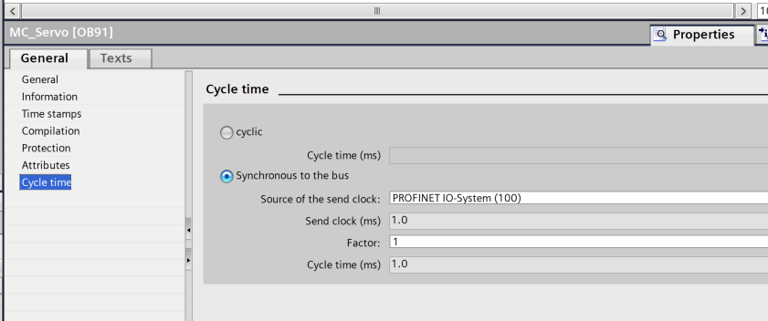
Synchronous to the bus
MC-Servo[OB91] is called either synchronously with the bus system or with a reduced ratio to the bus system. The transmit clock is set in the properties of the selected bus system. The following bus systems can be selected in the “Distributed I/O” drop-down list
- Isochronous PROFIBUS DP
- Isochronous PROFINET IO
It is important to note that MC-Servo [OB91] cannot be called in synchronization with a bus system connected to the CPU via a communications processor/communications module (CP/CM).
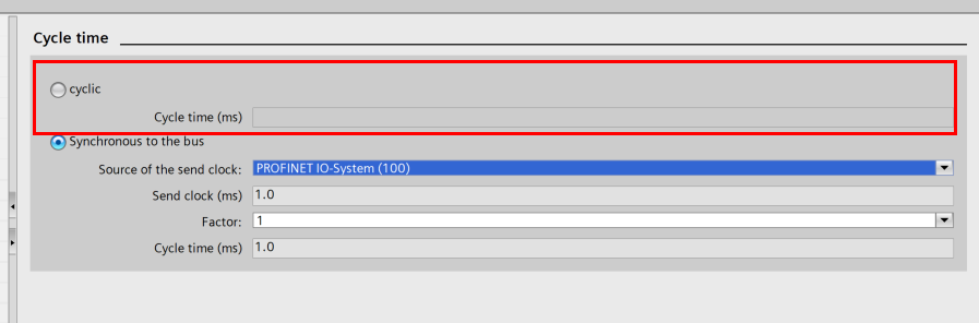
Cyclic
MC-Servo [OB91] is called periodically in the specified application cycle.
The selected application cycle must be long enough to process the technology object in one cycle; if the processing time of the technology object is longer than the application cycle, an overflow will occur. So, to achieve optimal control quality, the computation of the MC-PreServo [OB67], MC-Servo [OB91] and MC-PostServo [OB95] configuration blocks must be performed within the transmission cycle.
The execution time of MC-Servo [OB91] and MC-Interpolator [OB92] can be found in the extended instruction “RT_INFO”. Thereby the current application cycle (information in µs) of OB MC-PreServo[OB67] and MC-PostServo[OB95] can be read using the start information.
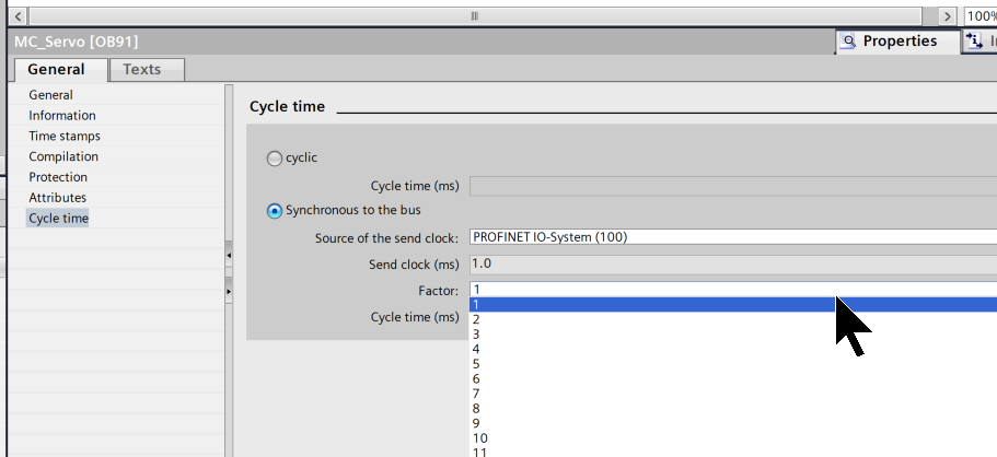
Reduction ratio (CPU V1.5 and higher)
It is possible to reduce the application cycle of MC-Servo [OB91] with respect to the transmit clock of an Isochronous PROFINET IO system. An integer multiple of the transmit clock can be set as a factor. If the Isochronous mode interrupt OB and MC-Servo [OB91] are called synchronously on the same PROFINET IO system, the same application cycle must be set for both OBs.
Priority
OB priority can be set as needed in the properties under “General > Properties > Priority”.
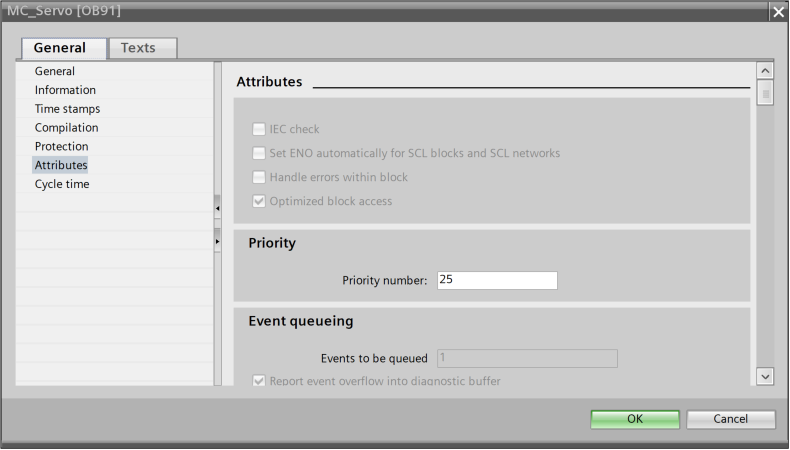
MC-Servo [OB91]
MC-Servo priority can be adjusted from 17 to 26 (default value 26).
MC-Interpolator [OB92]
MC-Interpolator priority can be adjusted from 16 to 25 (default value 24).
Becareful!
The priority of MC-Servo [OB91] must be at least one higher than the priority of MC-Interpolator [OB92]. The priority of the organization blocks MC-PreServo [OB67] and MC-PostServo [OB95] correspond to the priority of the MC-Servo [OB91]. MC-PreServo [OB67] is called immediately before MC-Servo [OB91]. MC-PostServo [OB95] is called immediately after MC-Servo [OB91].
The priority of MC-Servo [OB91] must be at least one higher than the priority of MC-Interpolator [OB92]. Also, in adjusting the priority:
- The priority of MC-PreServo [OB67] and MC-PostServo [OB95] OBs correspond to the priority of MC-Servo [OB91].
- MC-PreServo [OB67] is called immediately before MC-Servo [OB91].
- MC-PostServo [OB95] is called immediately after MC-Servo [OB91].
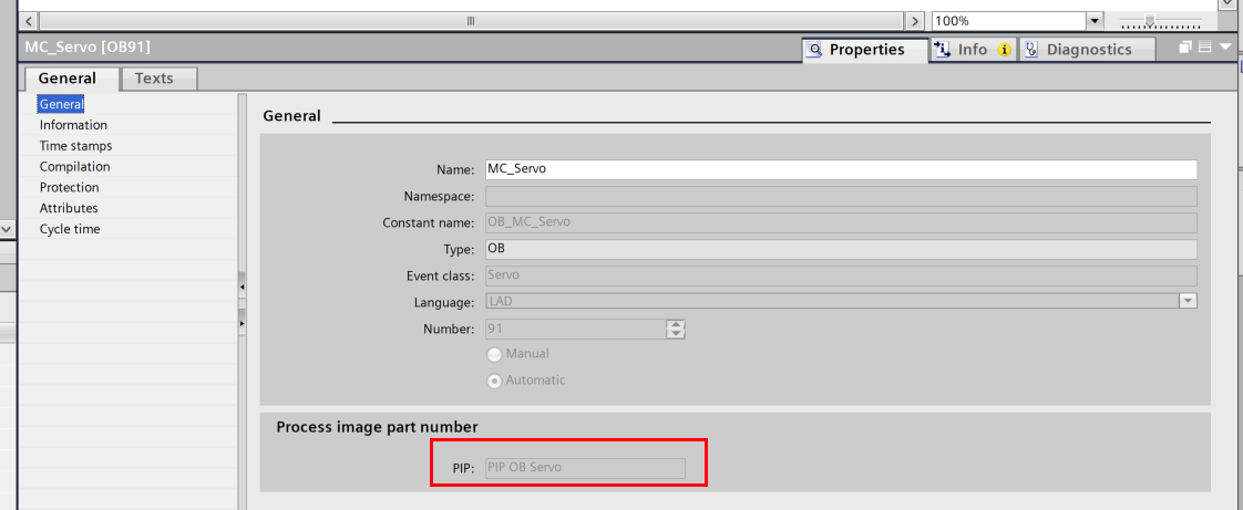
Process image partition “OB Servo PIP”
When MC-Servo[OB91] is invoked, the Process image partition “OB Servo PIP” becomes available in isochronous mode for motion control. All drives and encoders used by motion control are assigned to this process image partition.
MC-PreServo[OB67] and MC-PostServo[OB95] are automatically called from MC-Servo[OB91], so process image partitions are also automatically available. When MC-PreServo[OB67] is used, data is loaded when MC-PreServo[OB67] is started. And when MC-PostServo[OB95] is used, data is output after MC-PostServo[OB95] is started.
In addition, all I/O modules used by motion control must be assigned to this process image partition (e.g., hardware limit switches). This assignment ensures that the process is chronologically synchronized with the technology object. It is important to note that the input process image partition is updated even in STOP mode.
Operational Sequence and Timeouts
When processing motion control functions, OB MC-Servo [OB91] and MC-Interpolator [OB92] are called and processed in each application cycle. The remaining cycle time can be used to process user programs. Observe the following rules for error-free program execution:
- In each application cycle, the MC-Servo [OB91] must be started and fully executed.
- In each application cycle, the associated MC-Interpolator [OB92] shall at least be started.
The figure below shows an example of an error-free operation sequence in the processing of OB1.

Overflows
An overflow may occur if the configured application cycle is exceeded, for example, when technology objects or programs are added to MC-PreServo [OB67] or MC-PostServo [OB95].
If the transmit clock of MC-Servo[OB91] overflows, a message is generated in the diagnostic buffer of the CPU. The controller will no longer operate isochronously. If MC-Servo [OB91] overflows during an application cycle, the CPU will switch to STOP mode.
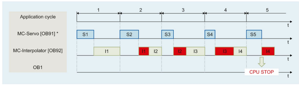
The following figure shows the behavior of MC-Servo[OB91] when it overflows in an application cycle and when it overflows in a transmit clock with reduction ratio=2:

The execution of MC-Interpolator [OB92] can only be interrupted by an MC-Servo [OB91] call. If further interrupts occur, the CPU switches to STOP mode.
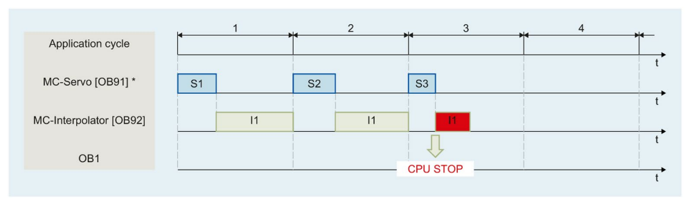
The CPU allows a maximum of three consecutive overflows of MC-Interpolator [OB92]. If more overflows occur, the CPU switches to STOP mode.
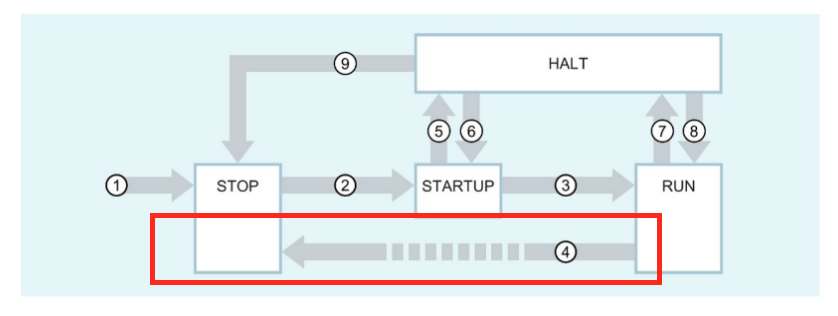
Operating modes
The last section describes the motion control behavior in each operating mode and transitions between operating modes.
STOP mode
In STOP mode, user programs are not processed and all process output is disabled. Technology data blocks are updated.
STARTUP mode
The startup OB processes once before the CPU begins processing the periodic user program. process output is disabled in STARTUP mode. Motion control jobs are rejected, but Technology data blocks are updated.
RUN mode
The user program is processed in RUN mode; in RUN mode, the programmed motion control jobs are periodically called and processed. Technology data blocks are then updated.
HOLD operating state
If Technology Object is used, the use of breakpoints is not supported. In each case, MC-Servo overflows. It immediately switches to STOP mode; in the HOLD operating state, no events are initiated and no user program is executed. All outputs are disabled or react according to the parameter settings. Outputs either supply a set alternate value or retain their last output value, placing the controlled process in a safe operating state.
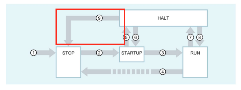
Operating mode transitions
Motion control behavior in transitions between operating modes is shown:
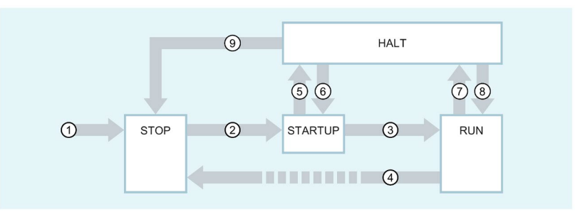
POWER ON → STOP
CPU restarts technology objects. The technology objects are reinitialized with the values of the load memory.
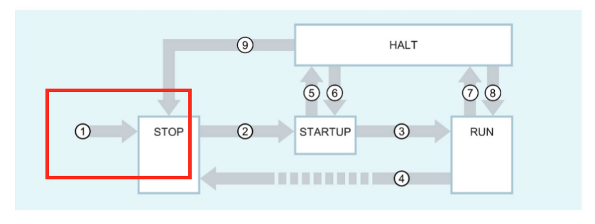
STOP → STARTUP
It has nothing to do with motion control.
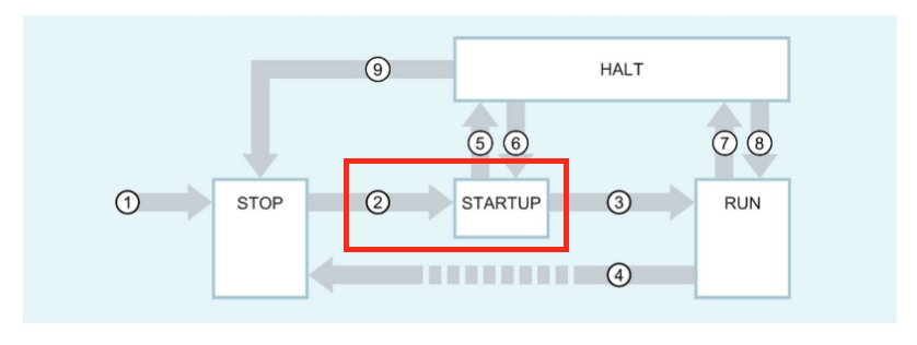
STARTUP → RUN
Process output is enabled.
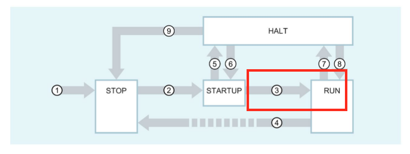
RUN → STOP
When the CPU switches from RUN mode to STOP mode, all technology objects are disabled according to the alarm response “remove enable”. If any restart-related data is changed for technology objects in RUN, the CPU will perform a restart of the corresponding technology objects.
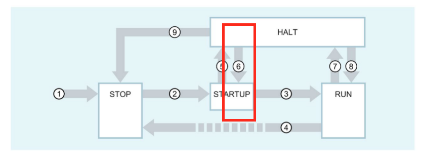
STARTUP → HOLD
This is when the breakpoint in the startup routine is reached.

HOLD → STARTUP
This is not possible when using technology objects.
RUN → HOLD
Breakpoints were reached.
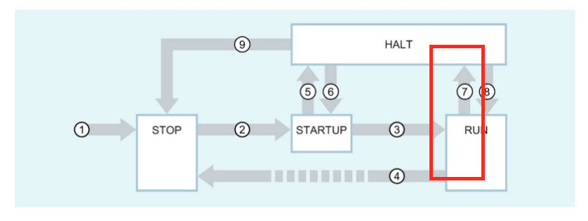
HOLD → RUN
This is not possible when using technology objects.
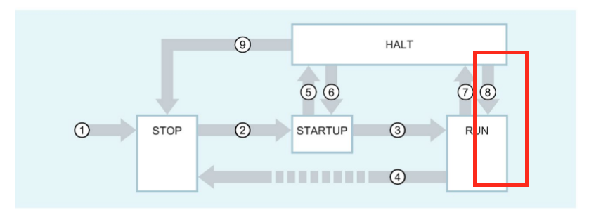
HOLD → STOP
Set to STOP by operating the switch/display or from the programming device.
Positioning axis technology object?
The positioning axis technology object? calculates the position setpoint taking into account the encoder settings and outputs the corresponding speed setpoint to the drive.
In position control mode, all movements of the positioning axis are performed as position control movements. In absolute positioning, the physical position of the positioning axis technology object must be known.
Each positioning axis is assigned a drive by means of a PROFIdrive telegram, an analog setpoint interface, or an encoder with PROFIdrive telegram.
The relationship between the encoder value and the defined position is established by the mechanical characteristics and parameter assignment of the encoder settings, as well as the homing operation.
The TECHNOLOGY OBJECT can also perform non-positional or relative positional movements without being in the homing state.
Implementation
The flow of this article is DRIVE settings on the WITTENSIEN side → hardware configuration on the TIA side → PROFINET settings → Technology Object construction → program creation.
WITTENSTEIN Side
First build the WITTENSTEIN side.
Software Version
You can check the current Servo Drive firmware from the MotionGUI2 tool. In this article, it is 03.02.00.
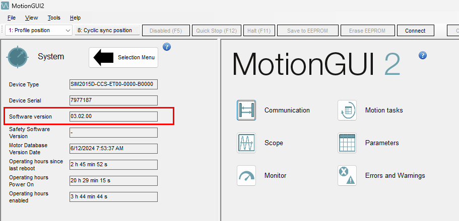
It is possible to set up a newer firmware Drive with older MotionGUI2, but you should download and use the latest version.
motor gear
Since we want to check the Gear ratio of the dynamic motor used in this article, click on Units>Unit perspective, and the basic setting is Motor/Input Side.
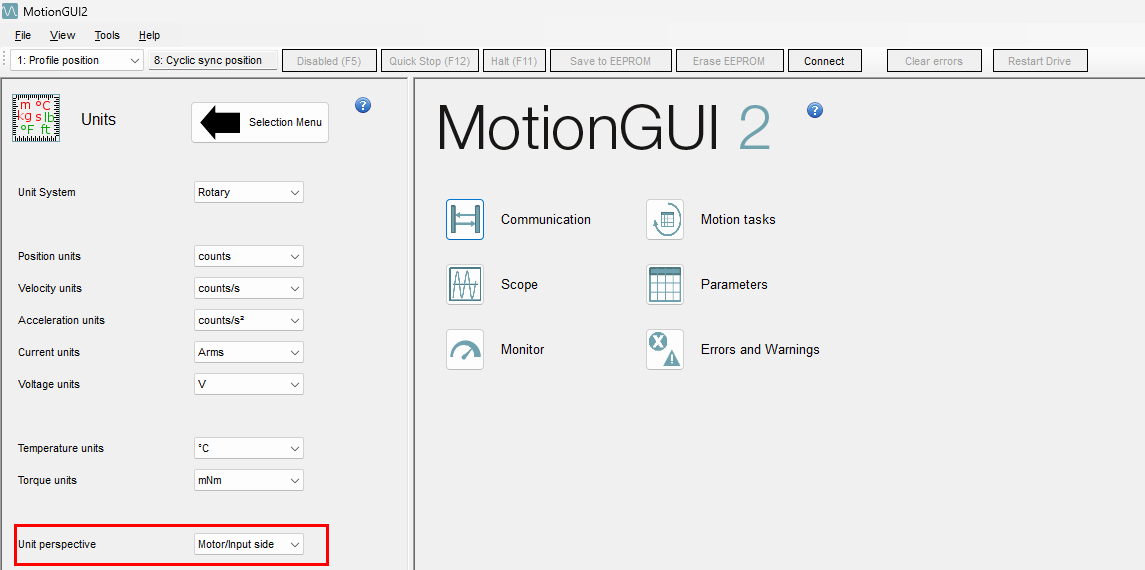
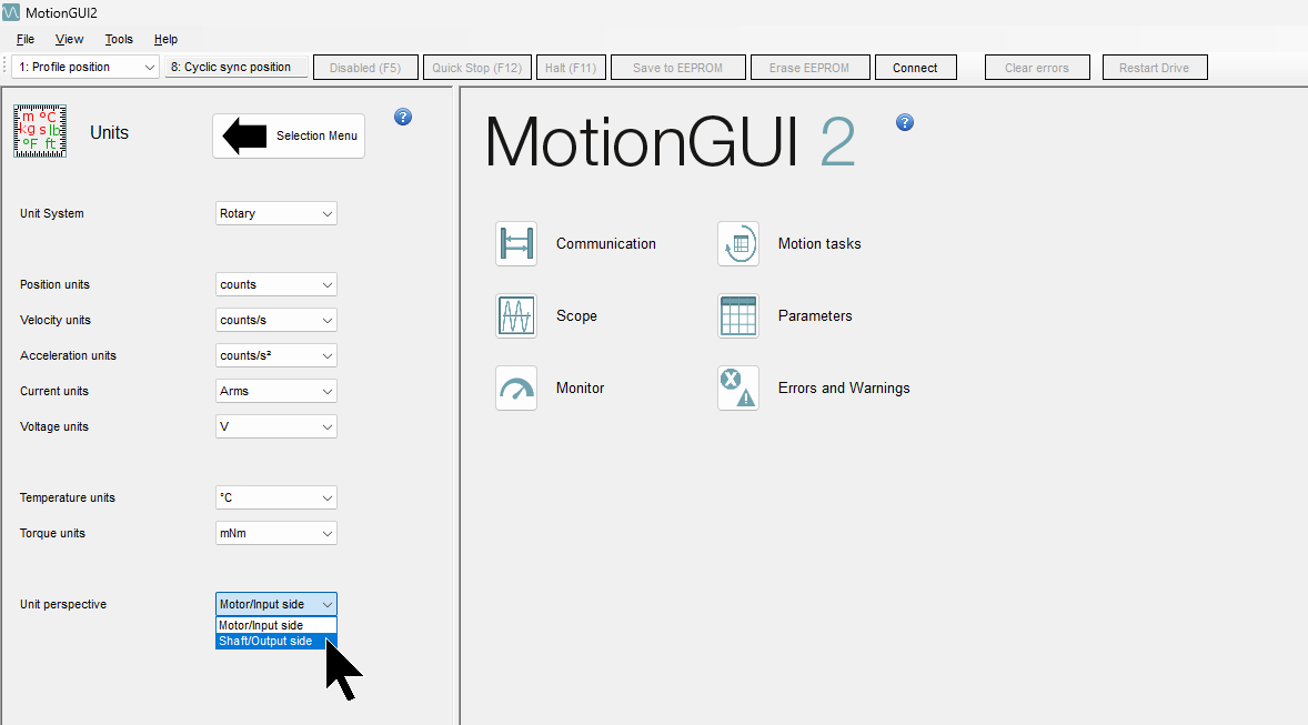
Select the Shaft/Output side from the drop-list.
You can see that the Motor gear ratio is 12. That would be Motor Gear ratio.
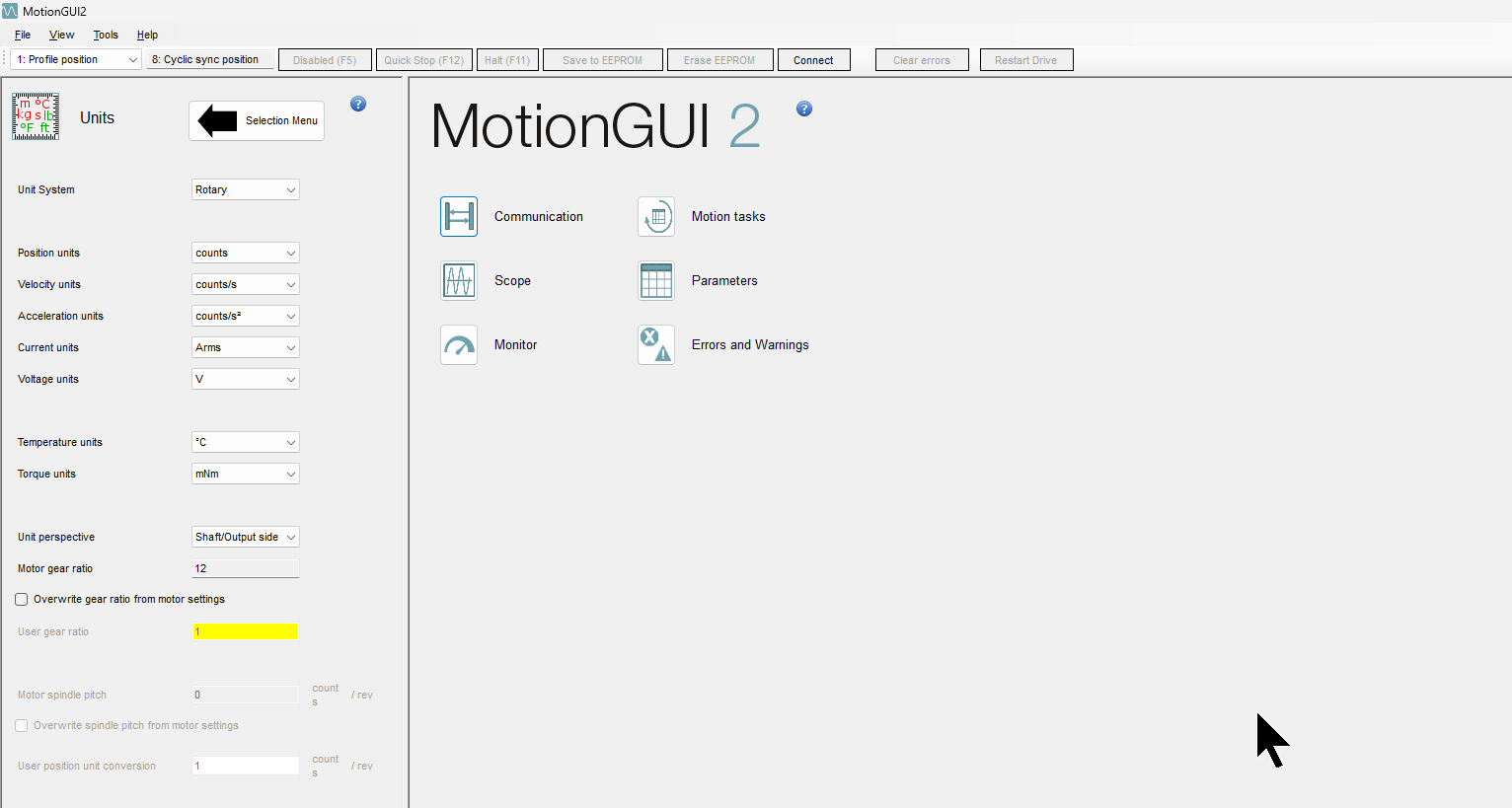
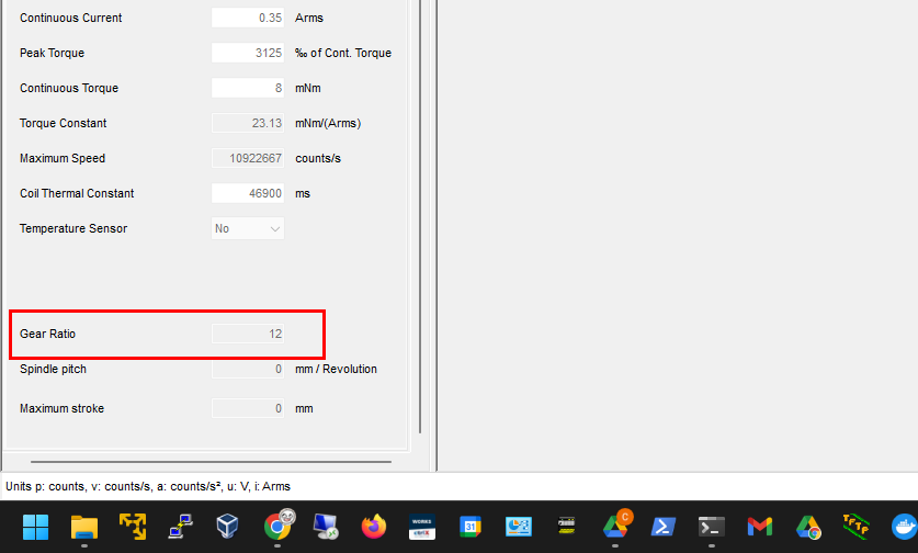
The same Gear ratio can also be found in the Motor item.
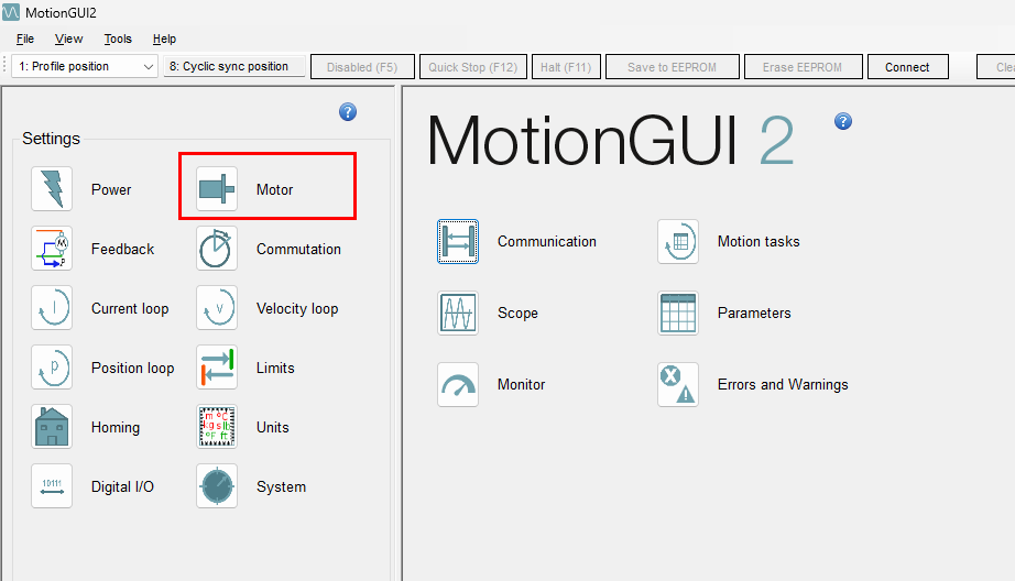
The Gear Ratio is found to be fixed at 12.
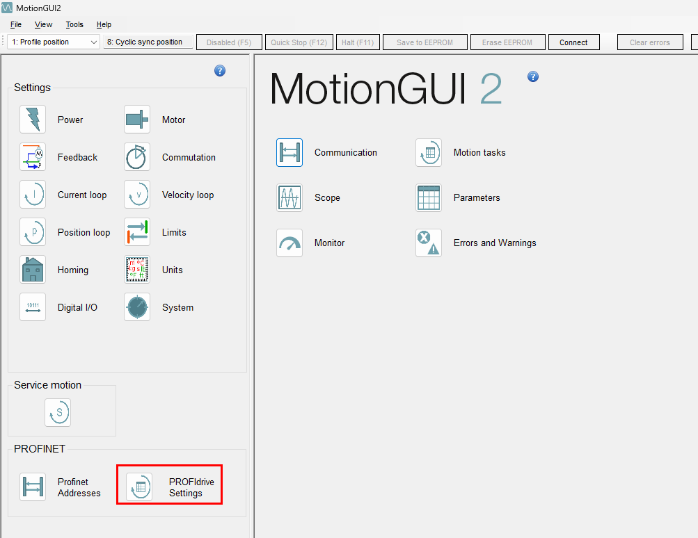
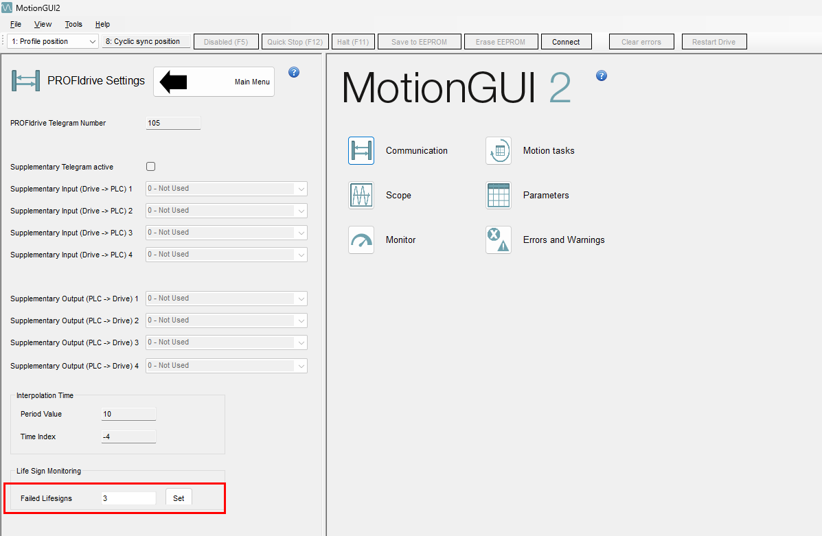
PROFIdrive Settings
Finally, let’s check the PROFIdrive settings.
It is the number of Life Sign Monitoring that you adjust in the process. Set it according to the actual network conditions.
Siemens Side
The next step is to build the Siemens S71200 G2 side.
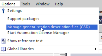
Installation of GSDML files
Click Options>Manage general station description files (GSD).
The GSDML administration screen will appear and click on the … button.

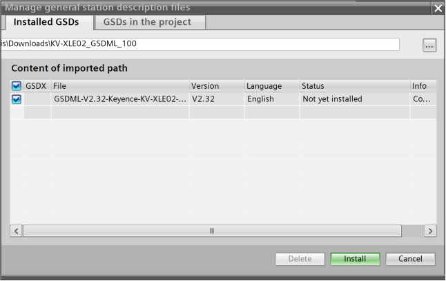
Select the GSDML Folder that was just downloaded.
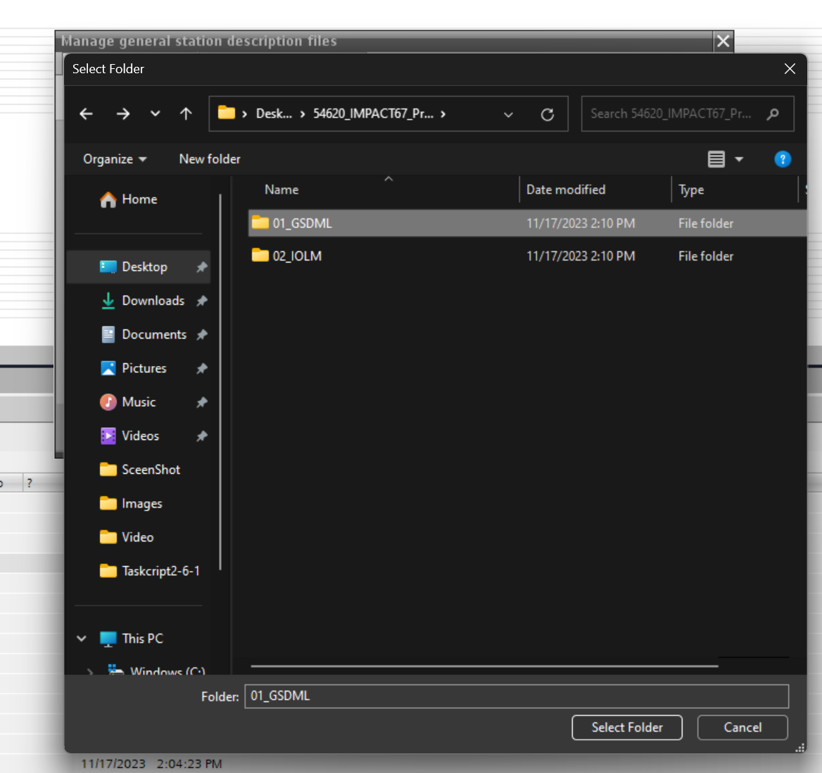
Done!
Hardware Configuration
Add WITTENSEIN servo motor
Add simco Drive2 from Catalog.
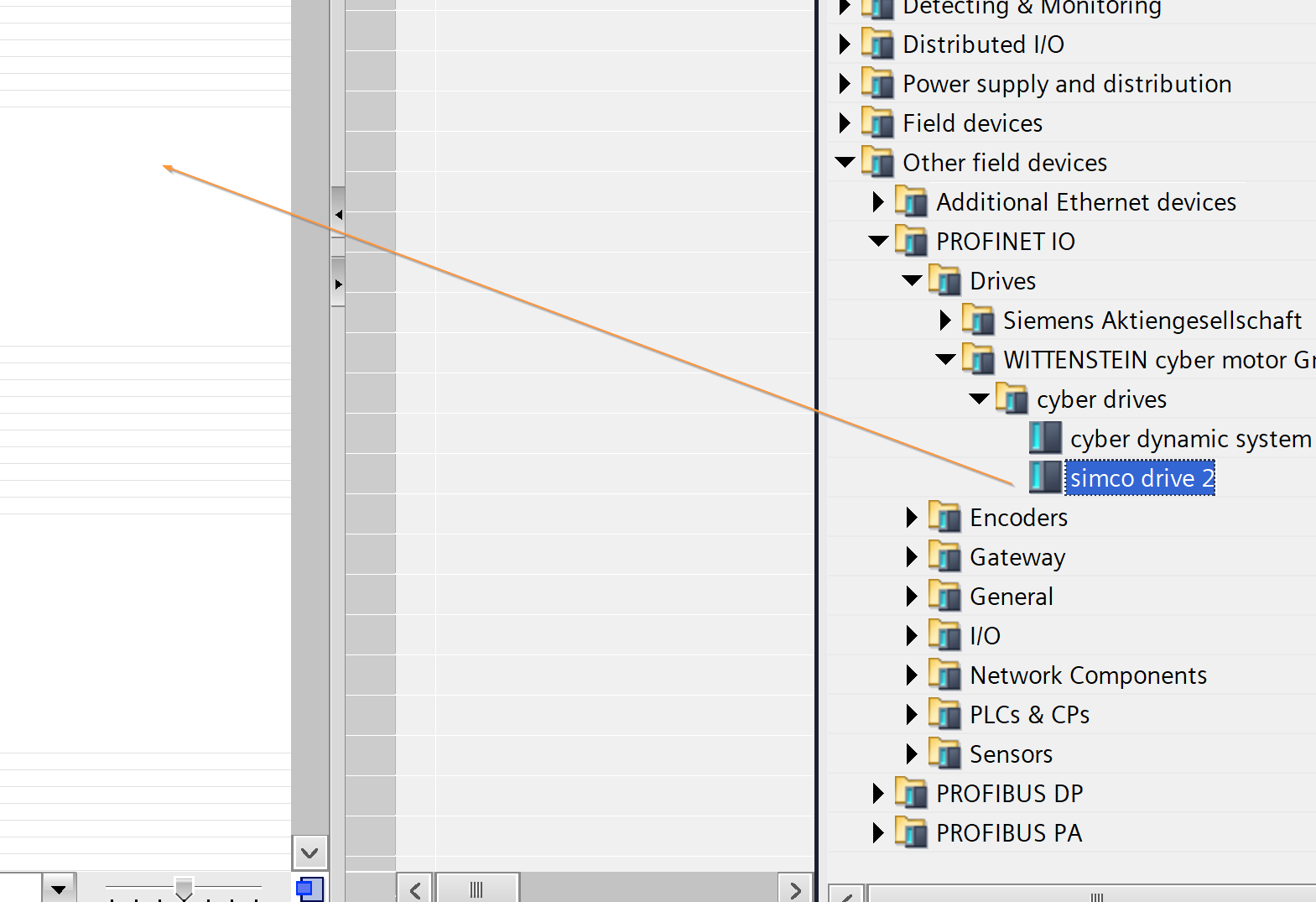
Done!
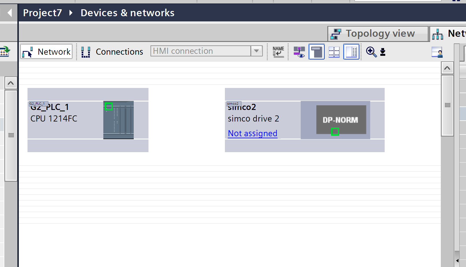
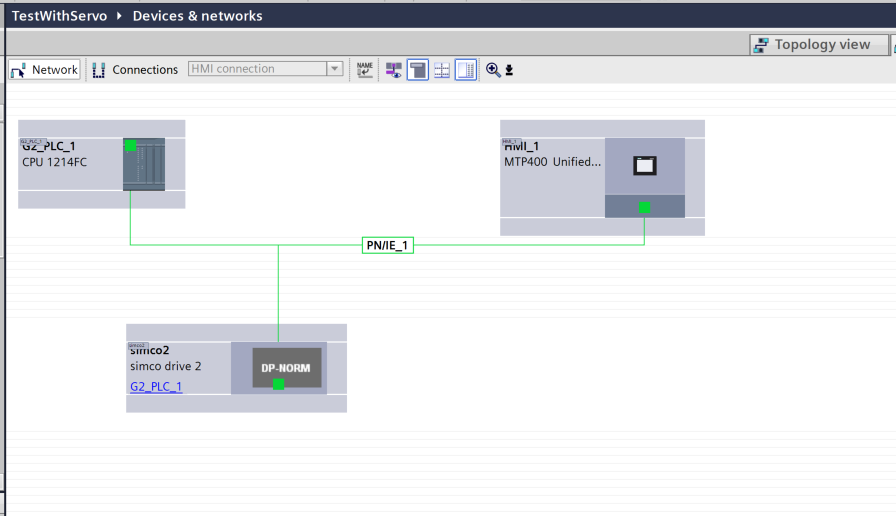
Profinet Network Assignment
Select “Not Assigned” in the SERVO MOTOR you just added and assign it to the same PROFINET network as the S71200G2.
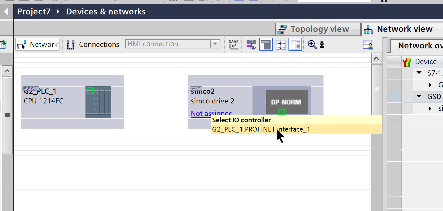
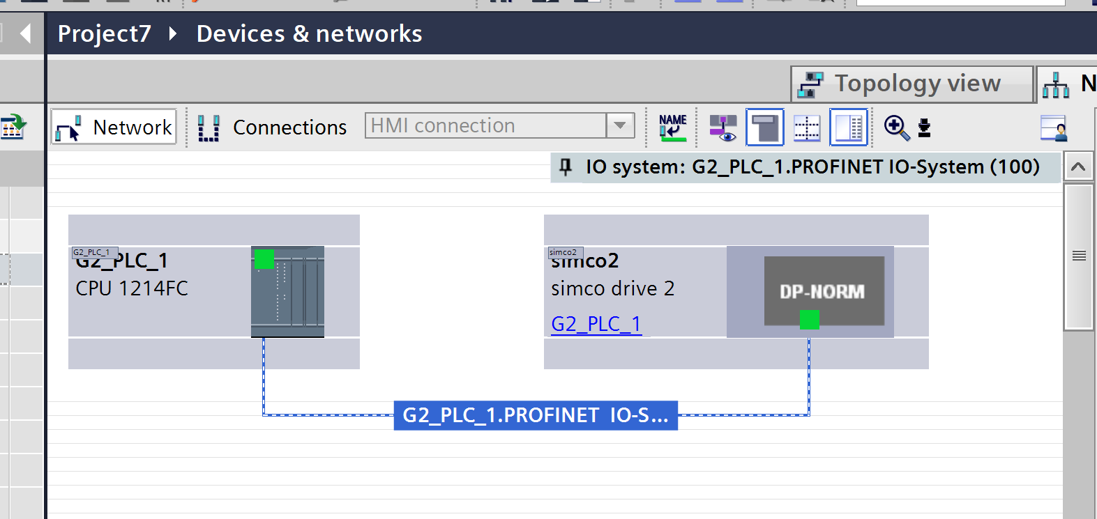
Done!
IP address settings
Click the button below to display the IP address of each device and set the IP address according to your application.
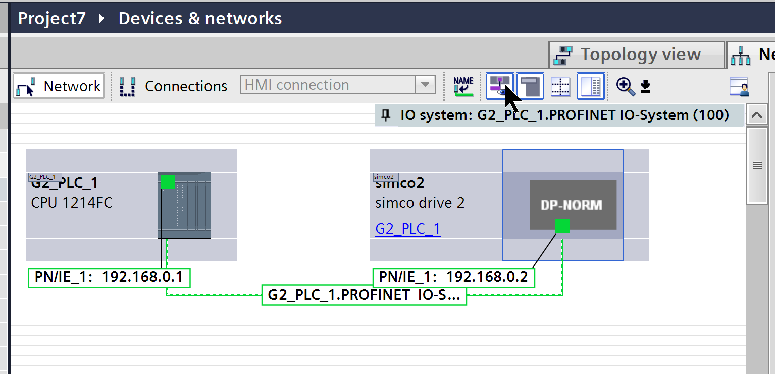
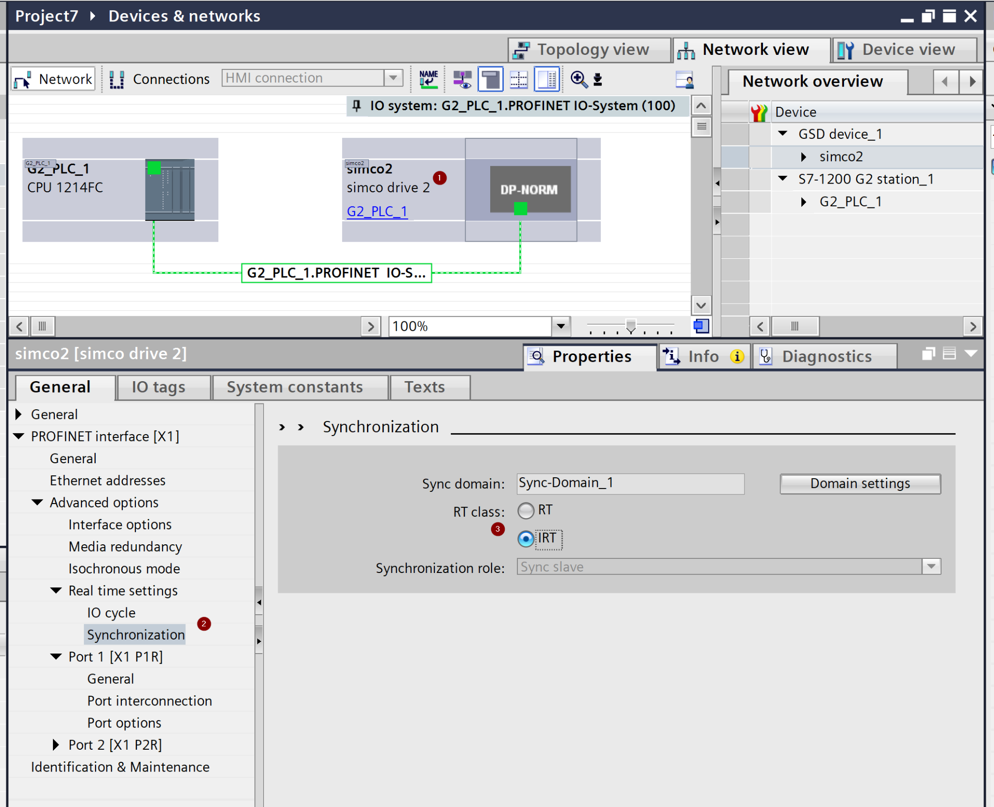
IRT Network Settings
Click on the WITTENSEIN servo motor, select PROFINET>Advanced options>Real time settings>Synchronization and set RT class to IRT.
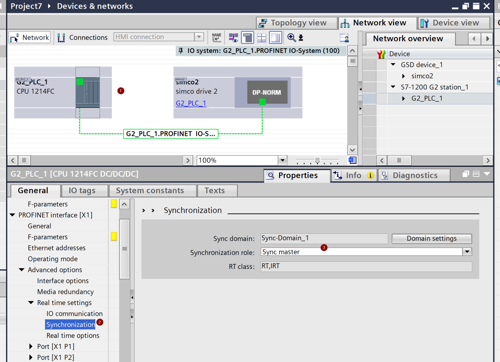
G71200-G2 PROFINET>Advanced options>Synchronization automatically changes to Sync master.
Topology Configuration
To build a PROFINET IRT network, the physical wiring of each IRT device must be configured. Now click on Topology View.
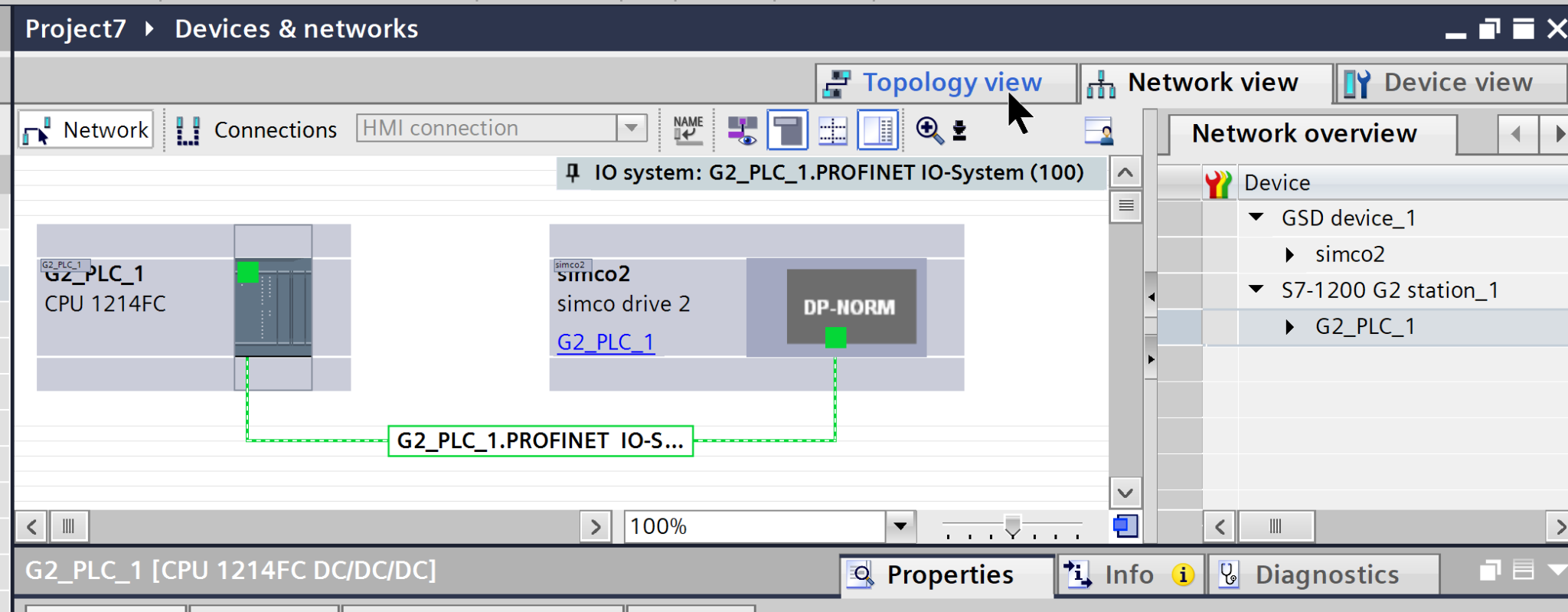
This is the Topology view.
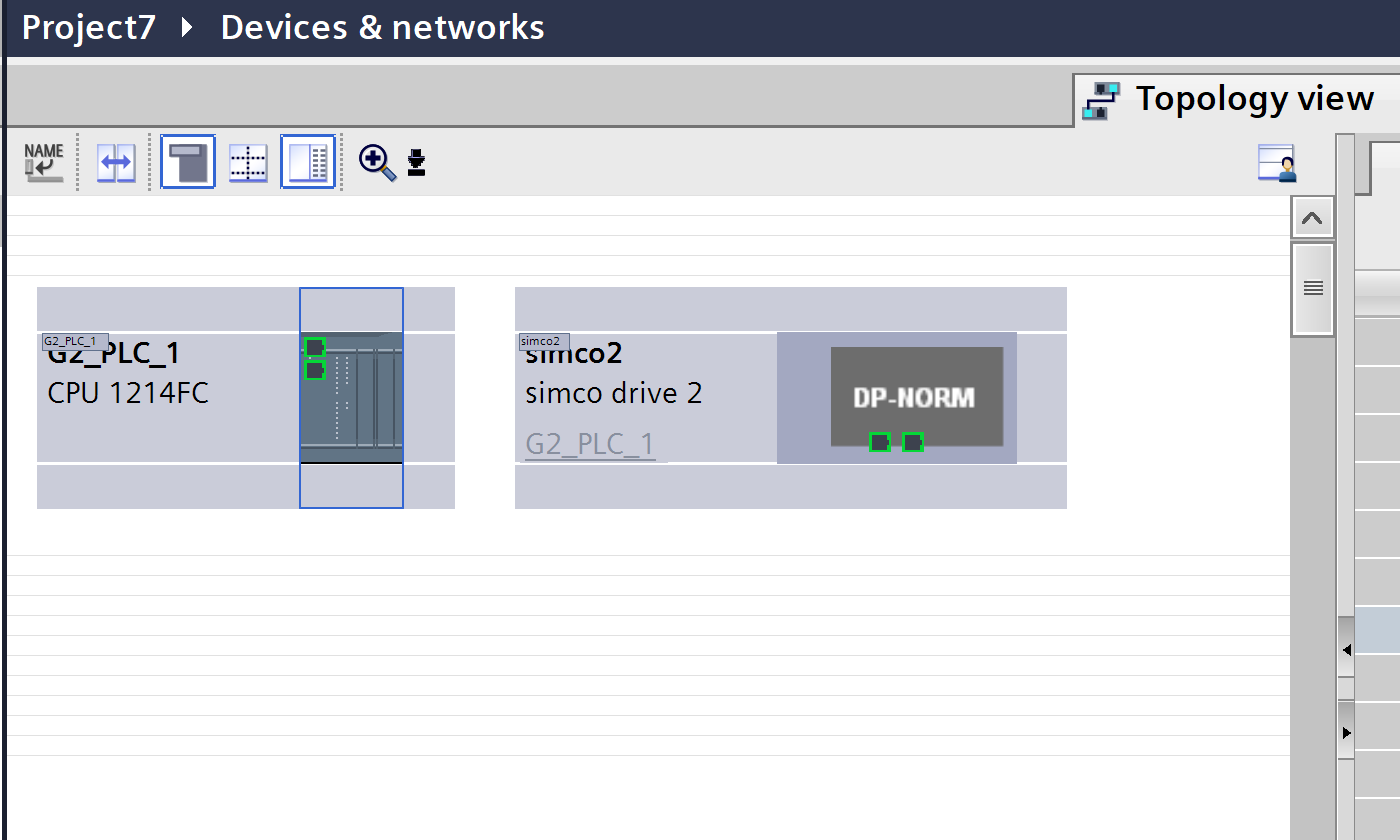
Configure each IRT device to match the actual physical wiring.
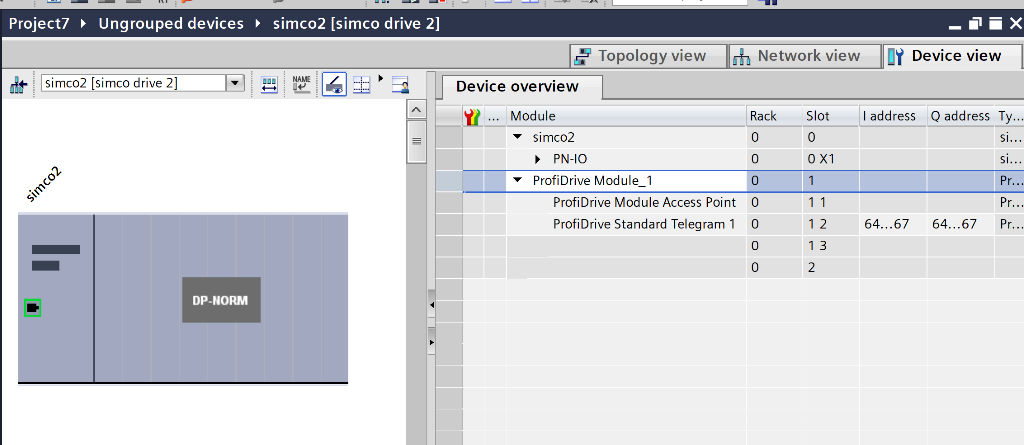
Telegram Settings
Set the communication Telegram for the WITTENSEIN servo motor; on Default, the Servo Drive communication module is set to Telegram1.
Right click on Telegram1>Delete to delete the Default Telegram settings.
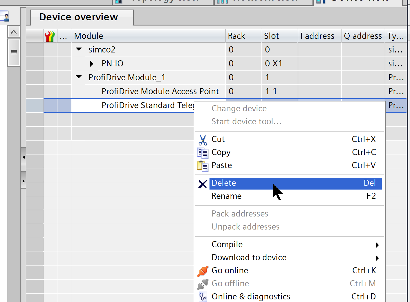
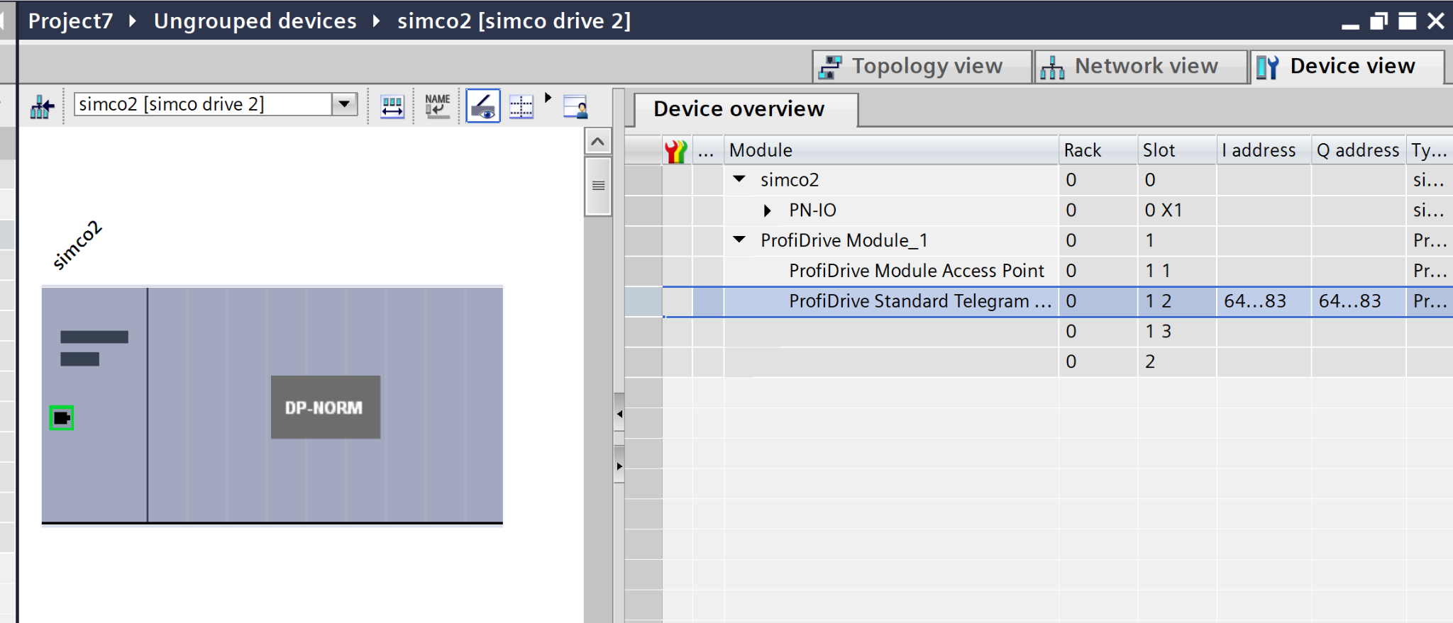
Next, add Telegram105 from Catalog.
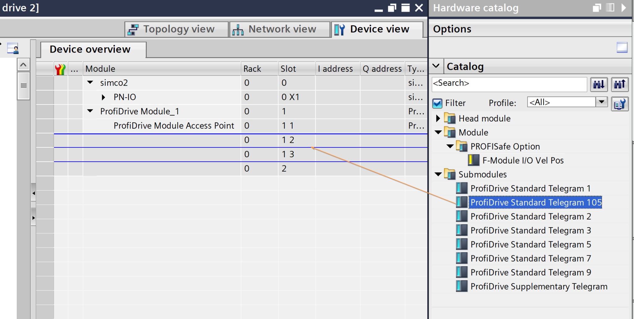
Done!
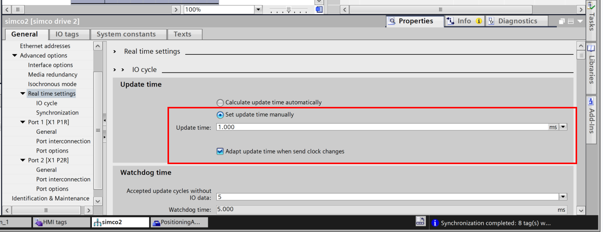
Realtime Settings-Update Time
Select WITTENSEIN servo motor and adjust Advanced options>Real time settings>Update time to match the actual network conditions.
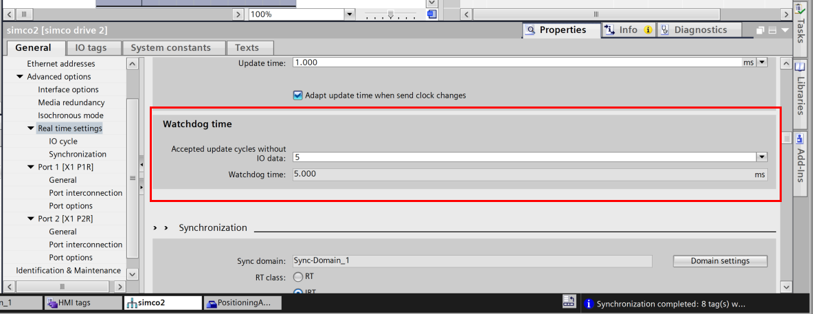
Watchdog time
Watchdog time should also be adjusted to match the actual network conditions.
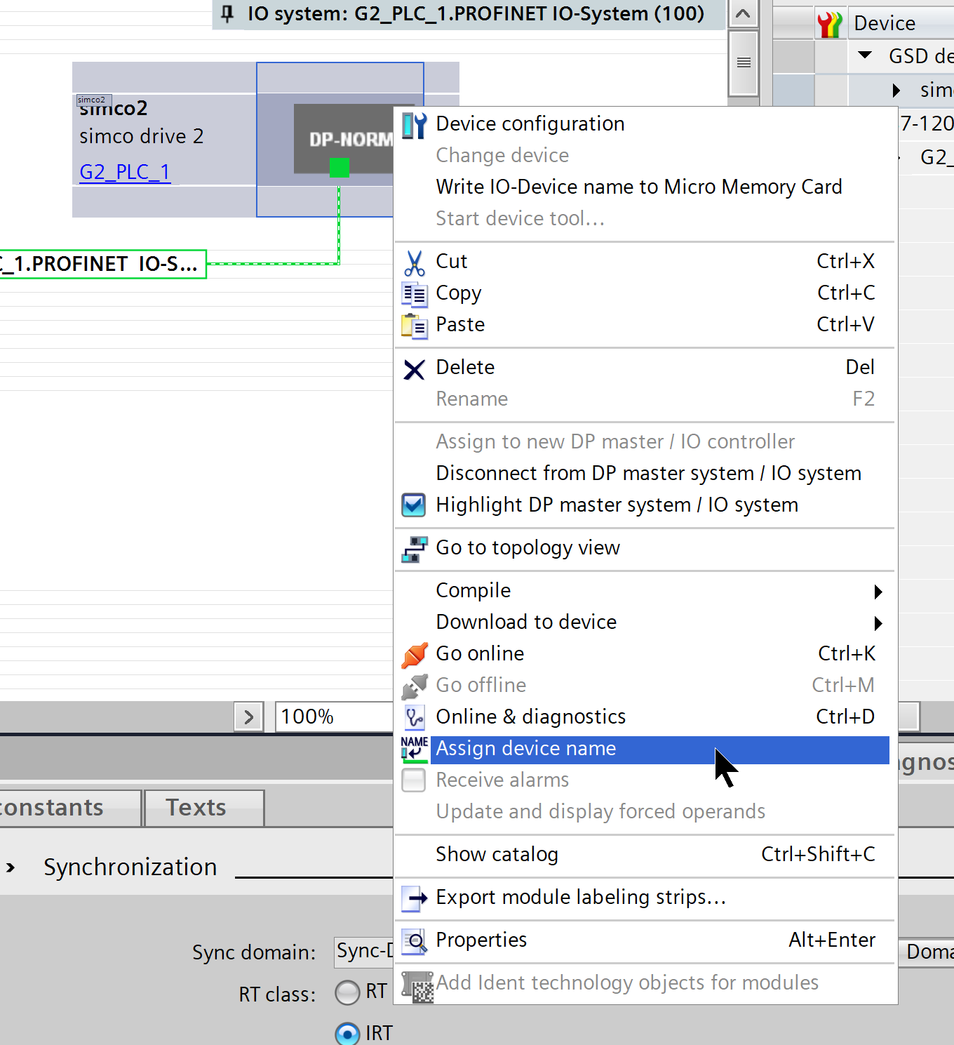
Assign device name
Right-click on the WITTENSEIN servo motor > Assign device name to set the PROFINET device name of the actual device.
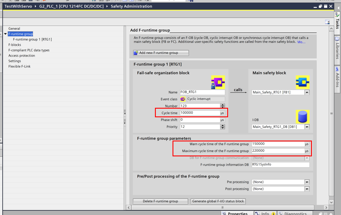
Safety Program Cycle Time
When using the Safety program, adjust Cycle time, Warn Cycle time, and Max Cycle time.
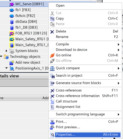
Configure MC_Servo
When using the Safety program, adjust Cycle time, Warn Cycle time, and Max Cycle time.
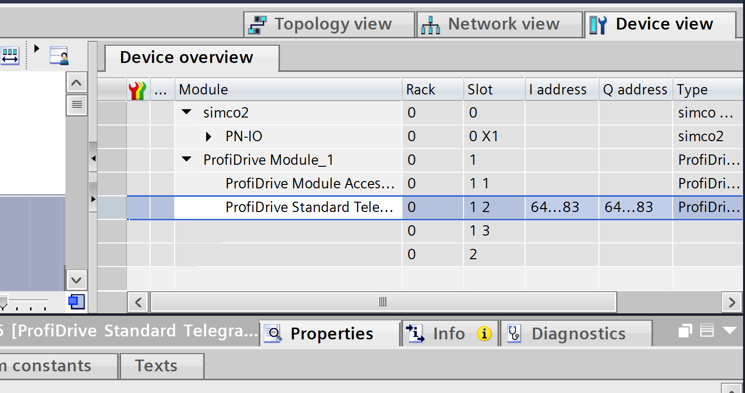
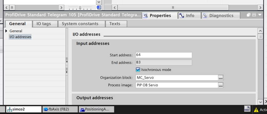
Next, let’s set the OB in WITTENSEIN servo motor no IOAddress>Input to MC_Servo.
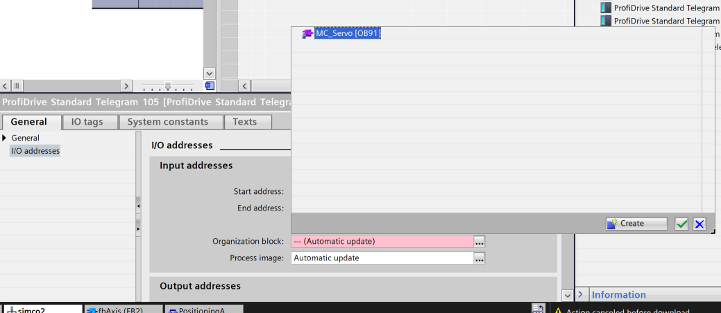
Done!
Also, set the OB in IOAddress>Output to MC_Servo.
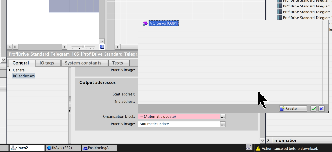
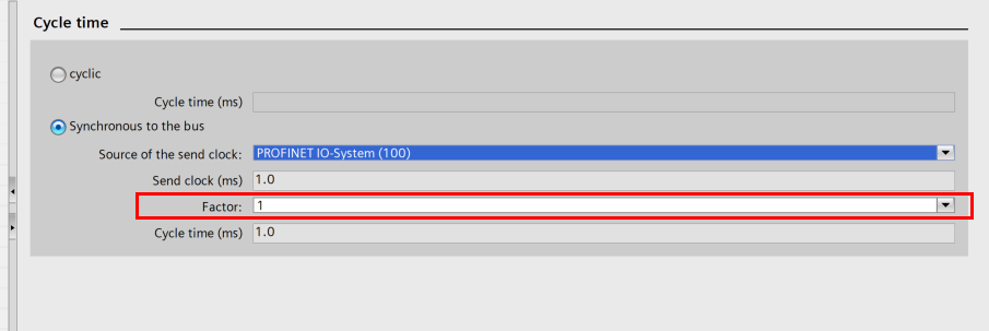
It can also be set to the cycle time of MC_Servo itself.
Open Cycle time and set >Factor to match your application.
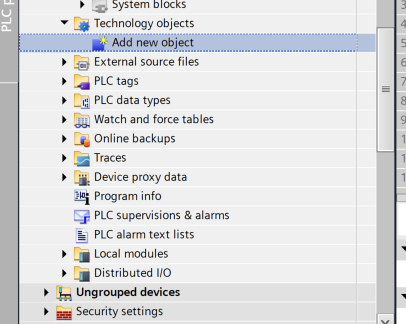
Insert Technology Object
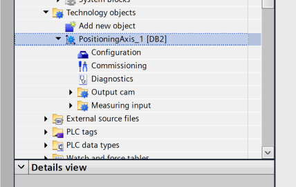
Now, to add a Technology Object, add a new Object with Technology Objects>Add new object.
Select TO_PositioningAxis (positioning axis) to be used in this article > OK to add Technology Objects.
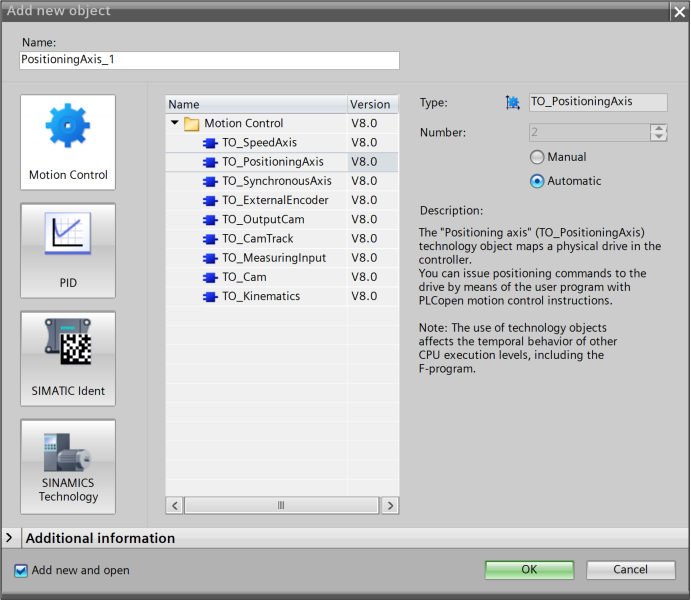
Done!
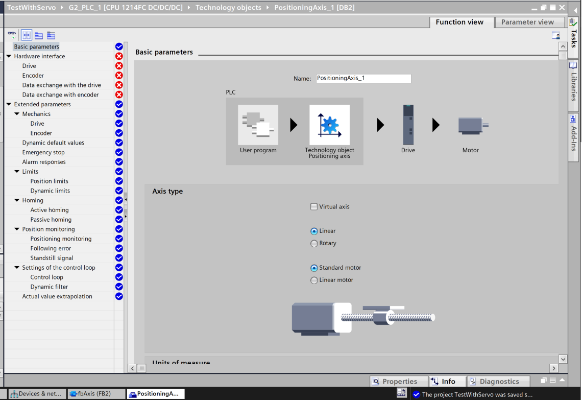
Configure Axis
Set the positioning axes you just added.
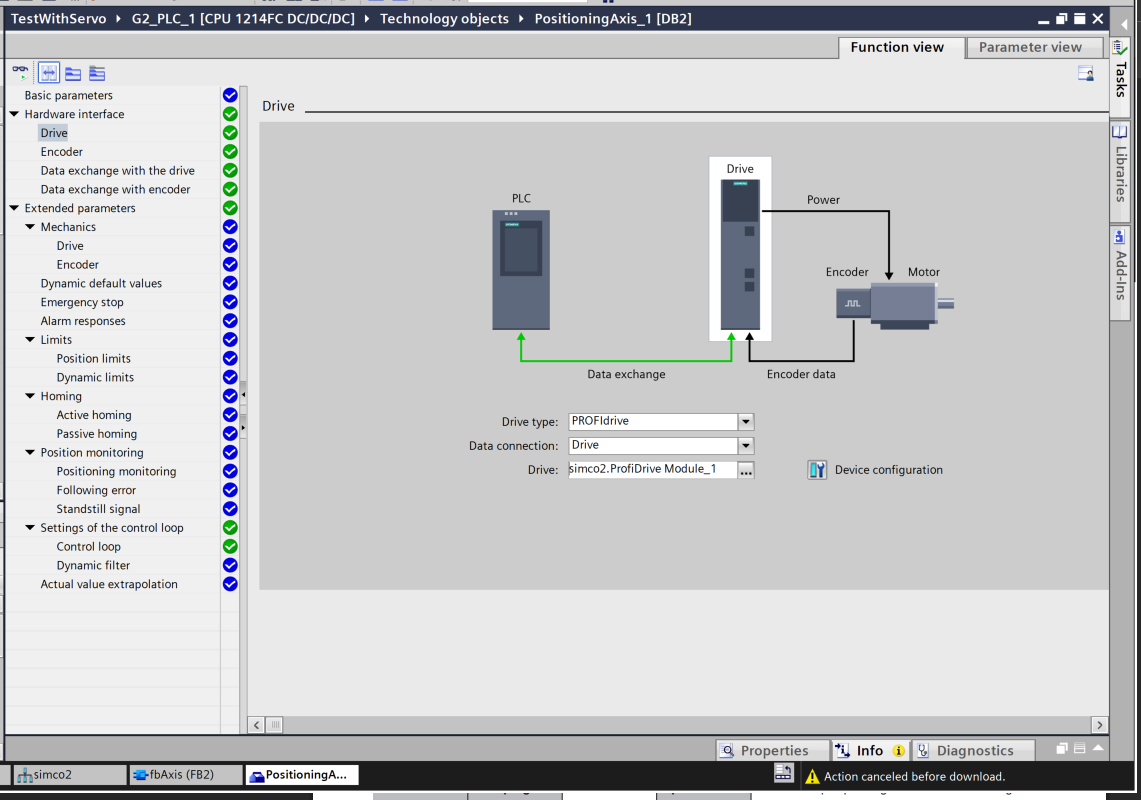
Hardware interface-Drive
Open the Drive item.
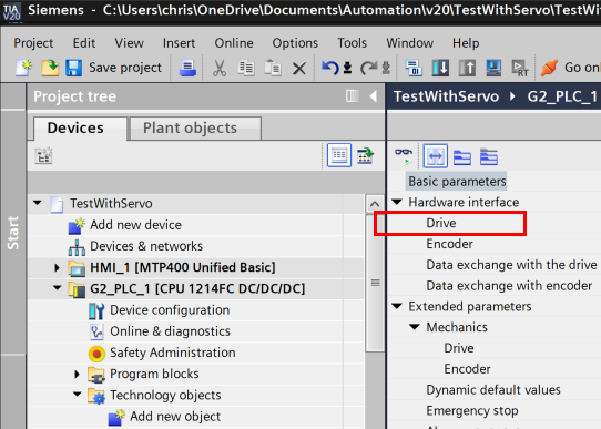
Click the … button next to the Drive item.
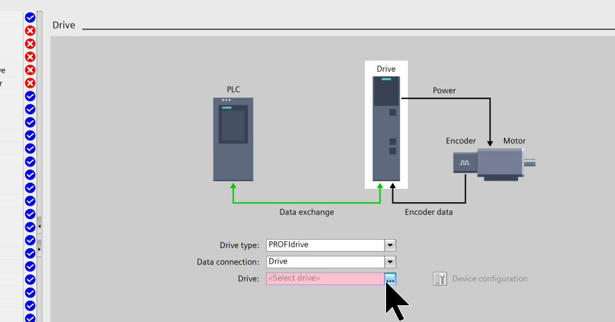
Select the WITTENSEIN servo motor you just added.
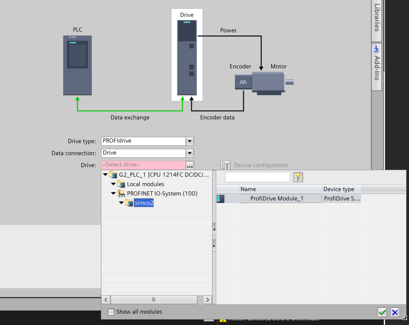
Done!
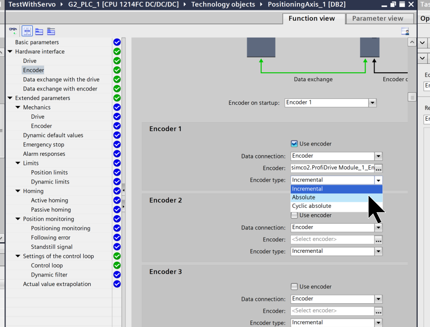
Hardware interface- Encoder
Select Encoder>Encoder1>Encoder Type to match the encoder type of the actual device.
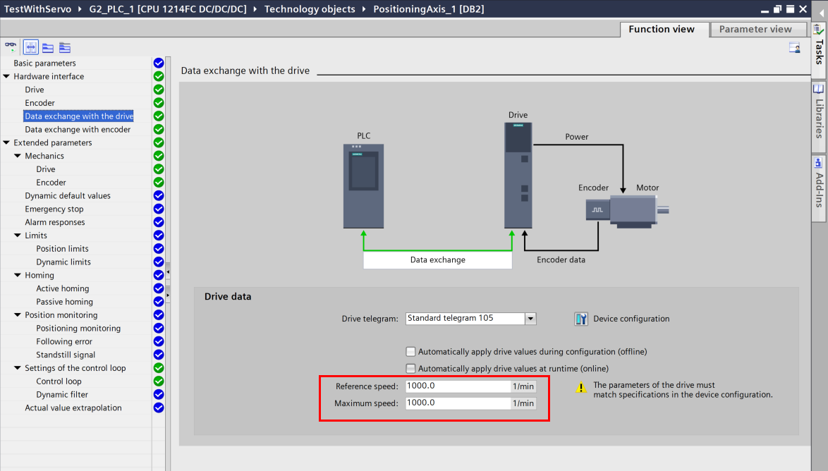
Hardware interface-Data exchange with the drive
In the Data exchange with the drive section, set Reference and Max Speed to match the application.
- Reference speed is the reference speed for this axis (speed treated as 100%)
- Maximum speed is the maximum speed limit in actual use.
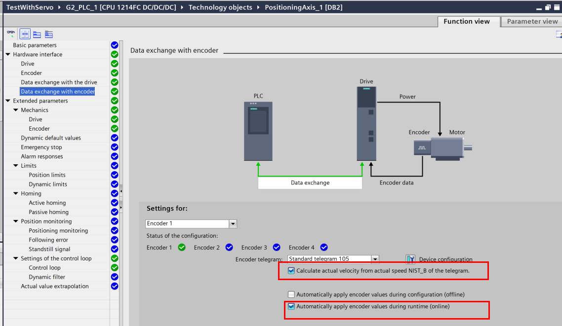
Hardware interface-Data exchange with encoder
Select the checkbox to transfer encoder parameters from the encoder configuration to the CPU. Encoder parameters are transferred from the bus after (re)initialization of the technology object and (re)startup of the encoder and CPU. Also, the encoder type must be the same for the axis configuration and the drive configuration.
Note that automatic transfer of encoder parameters is only possible with PROFIdrive encoders of product version A16. For this purpose, “Encoder” must be selected as the data connection in the configuration window. Also, to use the encoder with SINAMICS drives, product version > V4.x is required.
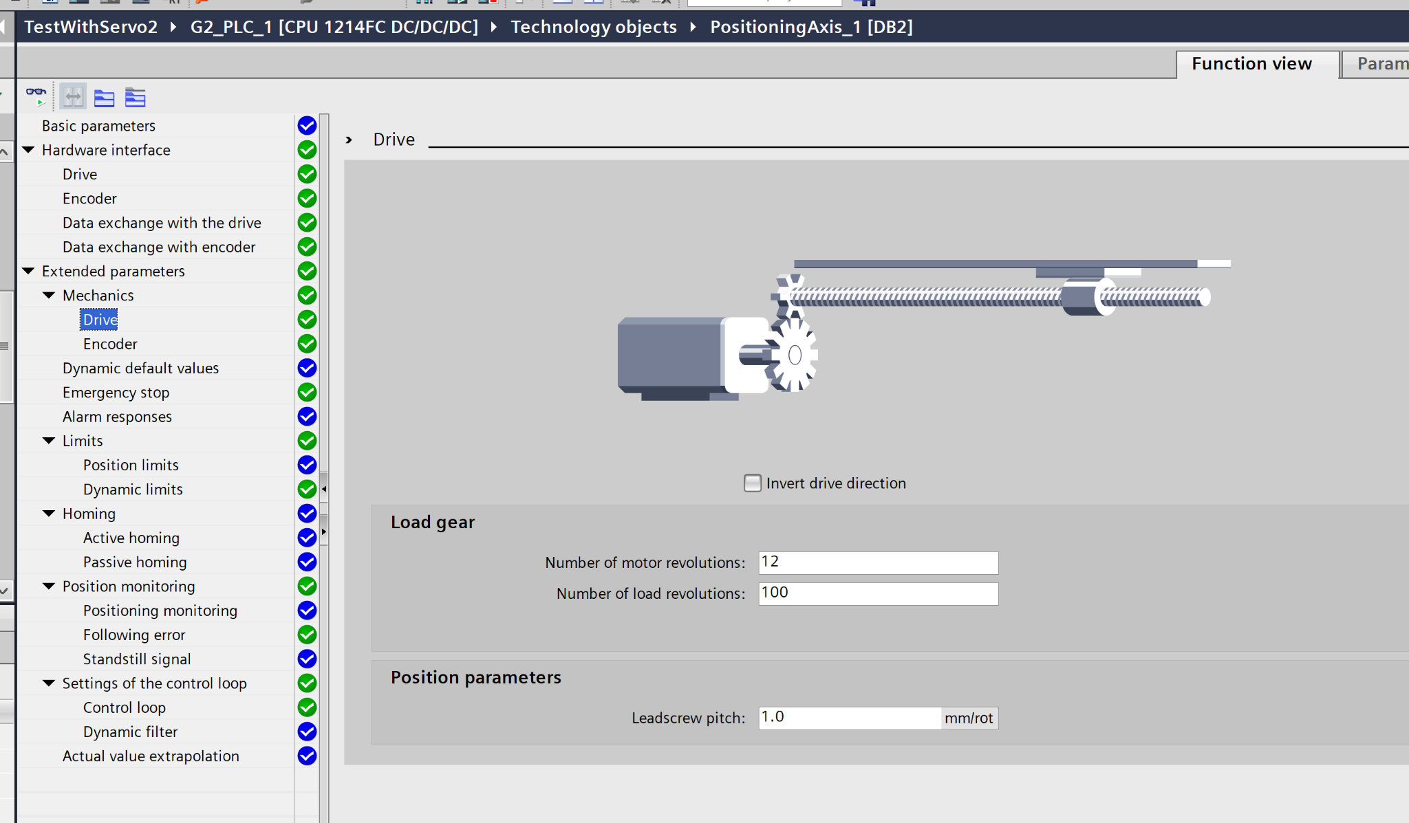
Extend parameters-Mechanics-Drive
The gear ratio of the load gear is defined as the ratio of the motor speed to the load speed. Also, the “Leadscrew pitch” sets the distance the load moves in one rotation.
- Number of motor revolutions RPM on the motor side: here the motor makes 12 revolutions
- Number of load revolutions Setting of 100 revolutions of the lead screw at 12 revolutions above
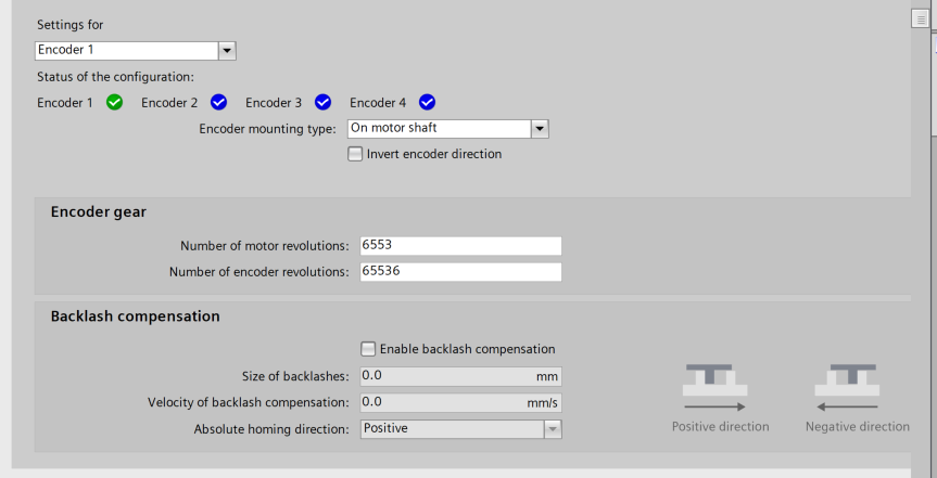
Extend parameters-Mechanics-Encoder
This field sets the load distance for one motor revolution. The gear ratio of the load gear is defined as the ratio of the motor speed to the load speed.
- Number of motor revolutions While the motor makes 6553 revolutions
- Number of encoder revolutions encoder counts 65536
Program
The next step is to create a program.
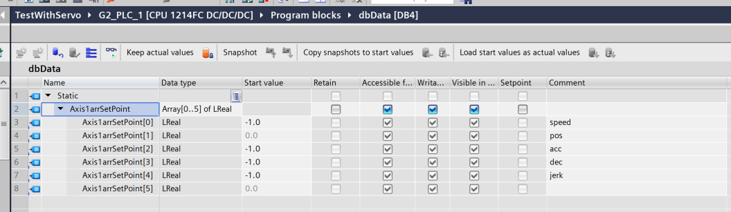
dbData
The DB of the WITTENSEIN servo motor functions as an AxisSetPoint array for motion control. It thereby makes the program simple to code and pass between blocks, since the parameters are handled in a single array.
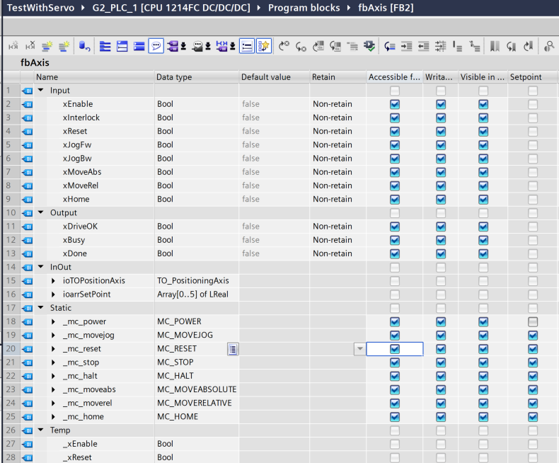
fbAxis
The next step is to create a FB that controls the WITTENSEIN servo motor.
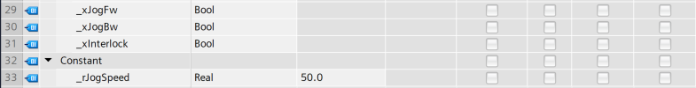
Interface
This is the fbAxis interface, a reusable module that generalizes FB by passing variables such as Technology Object and acceleration/deceleration as IO parameters, and handles servo motion control of a single axis in an integrated manner.
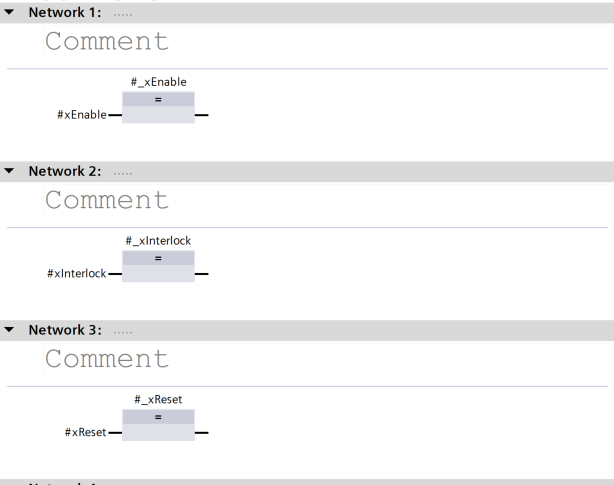
Network1
This is the Servo ON signal, interlock and reset signal of Technology Object.
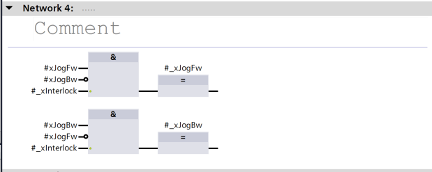
Network4
Here is a program for Jog Fw/Bw interlock and command issuance for Technology Object.
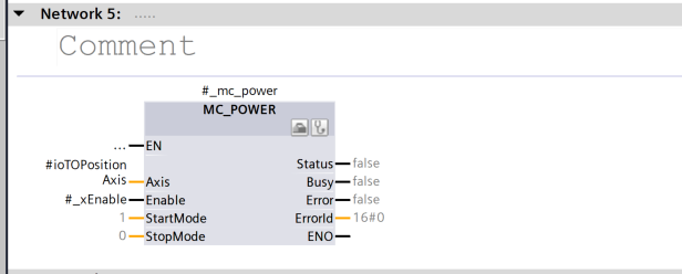
Network5
This block is an instruction to supply servo power (electrical power) to the axis (Axis). This puts the specified axis in a ready-to-operate state. This block is the first step in applying power to an axis. It is usually always executed before other motion instructions such as MC_MOVE and MC_HOME.
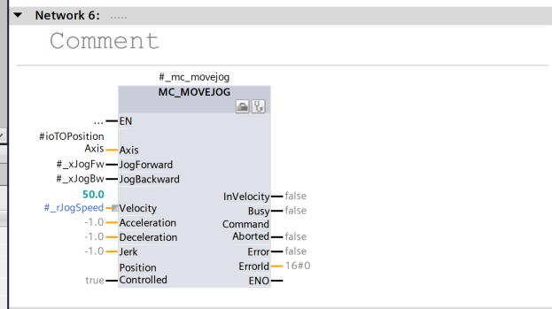
Network6
This is an instruction block that performs “Jog Operation” and is used for applications such as moving forward or backward at a constant speed.
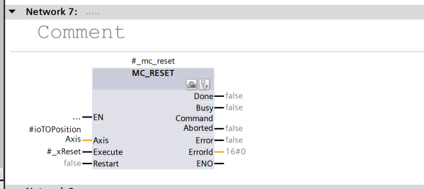
Network7
This is an instruction block that resets the error condition of the motion control axis.
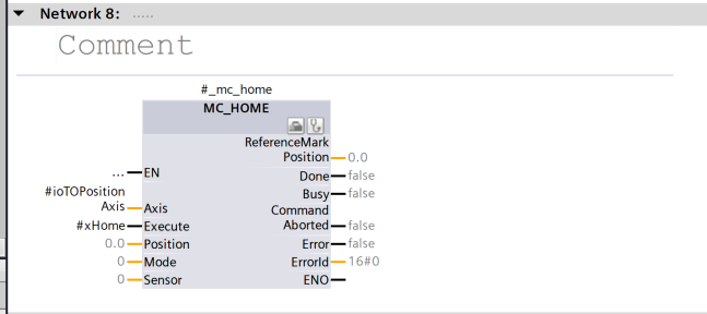
Network8
This block moves the axis to the home (origin) position and processes it as the basis for subsequent operations.
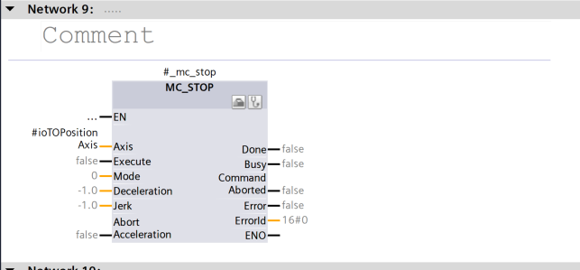
Network9
This block slows down and stops the running motion (movement).
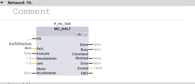
Network10
MC_HALT is an instruction to execute “immediate halt (Halt)”.
It is more urgent than MC_STOP, forcing the speed to stop near zero at the current position, but maintaining the “target position” on the motion control, etc.
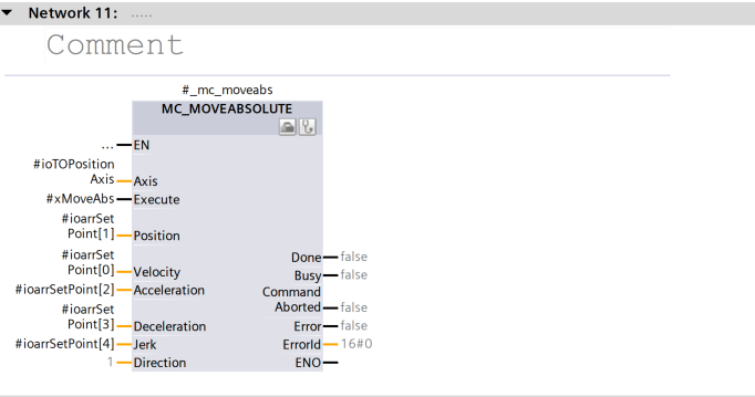
Network11
This is an instruction block that moves the axis to the specified absolute coordinates.
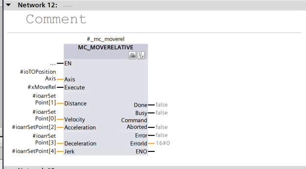
Network12
This instruction block is an instruction block that moves the axis by a distance relative to the current position.
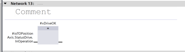
Network13
This instruction block is an instruction block that moves the axis by a distance relative to the current position.
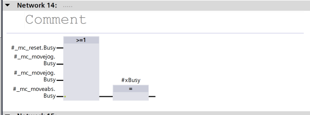
Network14
This one aggregates the Busy flags of multiple motion blocks and sets xBusy to TRUE if any one of them is TRUE. Also, the >=1 operation block is an OR condition that determines if one or more of the input signals are TRUE.
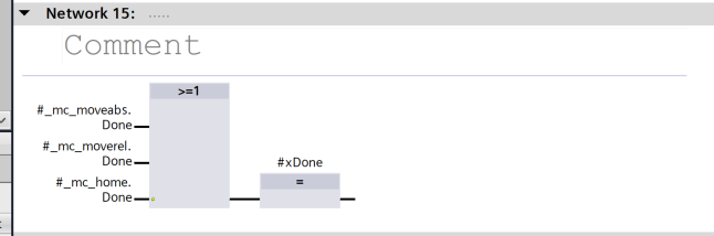
Network15
This aggregates multiple Done flags and sets xDone = TRUE if any of them are TRUE. This is also an aggregation of OR conditions with >=1.
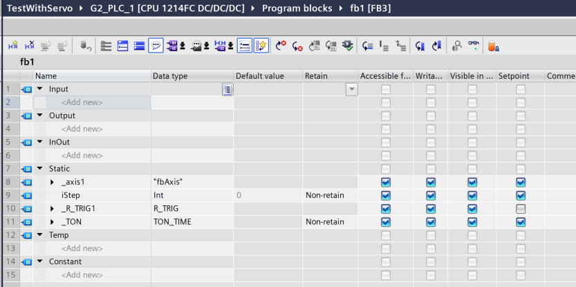
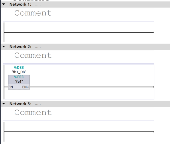
fb1
This is the declaration section of fb1.
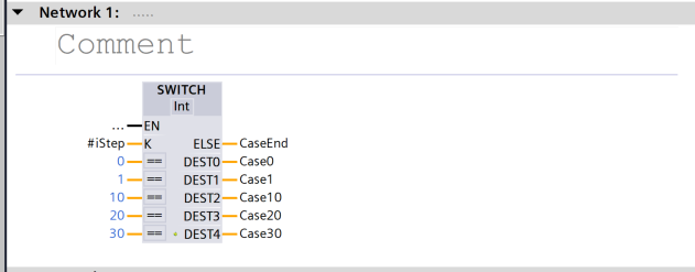
Network 1:SWITCH #iStep
Jumps to Case0 to Case30 according to the step number (#iStep).
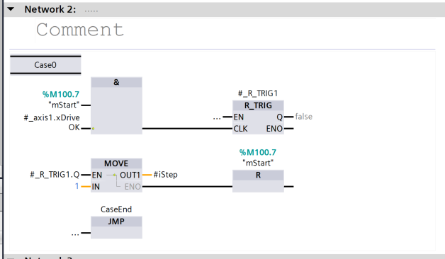
Case0 (Network 2): Starting Condition
%M100.7 (mStart) is ON and _axis1.xDriveOK is TRUE → Rising edge is detected (R_TRIG). Also, advance iStep to 1 to reset %M100.7 (one-time activation).
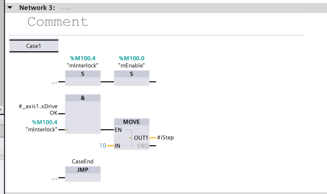
Case1(Network 3)
Interlock check → MC_POWER enable
Set DriveOK to TRUE and %M100.4 (mInterlock) to TRUE → %M100.0 (mEnable) and also set iStep = 10.
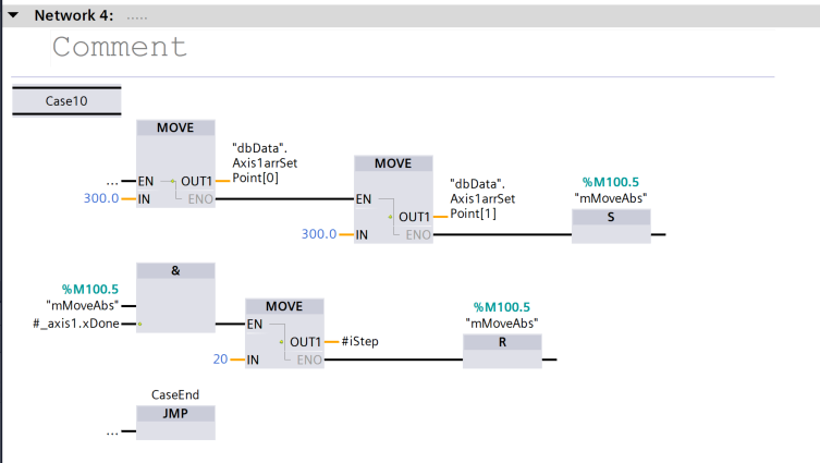
Case 10 (Network 4): Absolute position shift
AxisSetPoint[0] = 300.0 (position)
AxisSetPoint[1] = 300.0 (velocity)
Set %M100.5 (mMoveAbs) → MC_MOVEABSOLUTE is executed in fbAxis
After completion, go to iStep = 20 and reset %M100.5
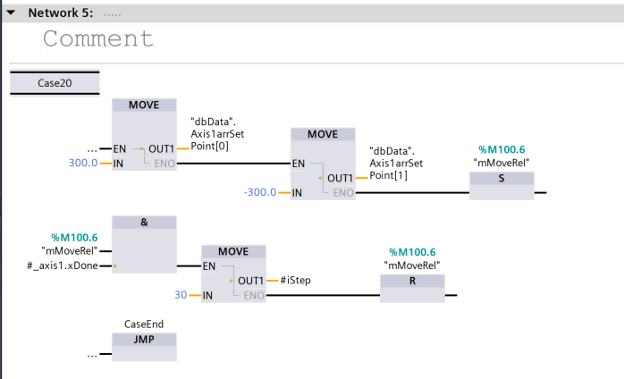
Case 20 (Network 5): Relative movement
AxisSetPoint[0] = 300.0, AxisSetPoint[1] = -300.0, set %M100.6 (mMoveRel) → MC_MOVERELATIVE with fbAxis. Then after exit, iStep = 30, mMoveRel reset
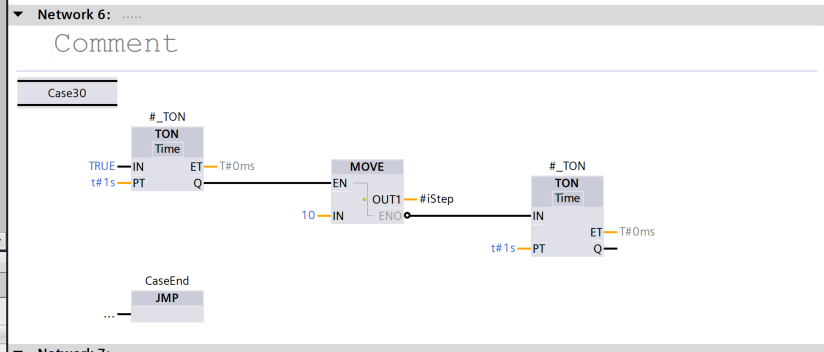
Case 30 (Network 6): Pause by timer
TON timer to stop for 1 second, then return to iStep = 10 after stop (restart loop).
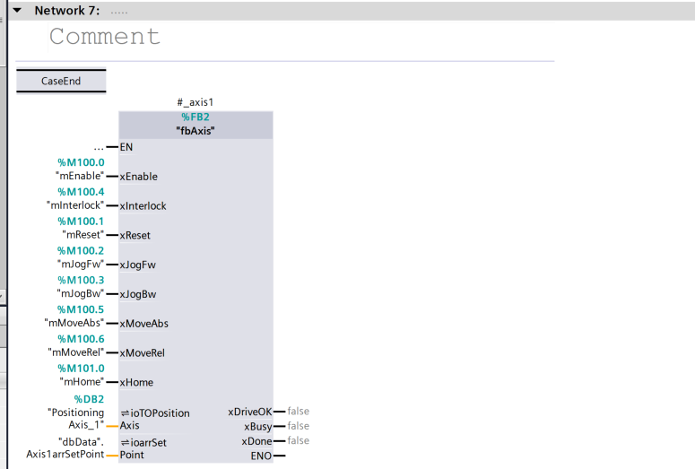
Network 7
In FB2, as we have seen in the previous configurations, MC_POWER, MC_MOVEABS, MC_MOVEREL, etc. are integrated into one, and motion control is triggered by each memory bit (%M100.x) from FB3.
Call from OB1
Within OB1, fb1 (FB3) is called and the axis control step sequence is always cycled.
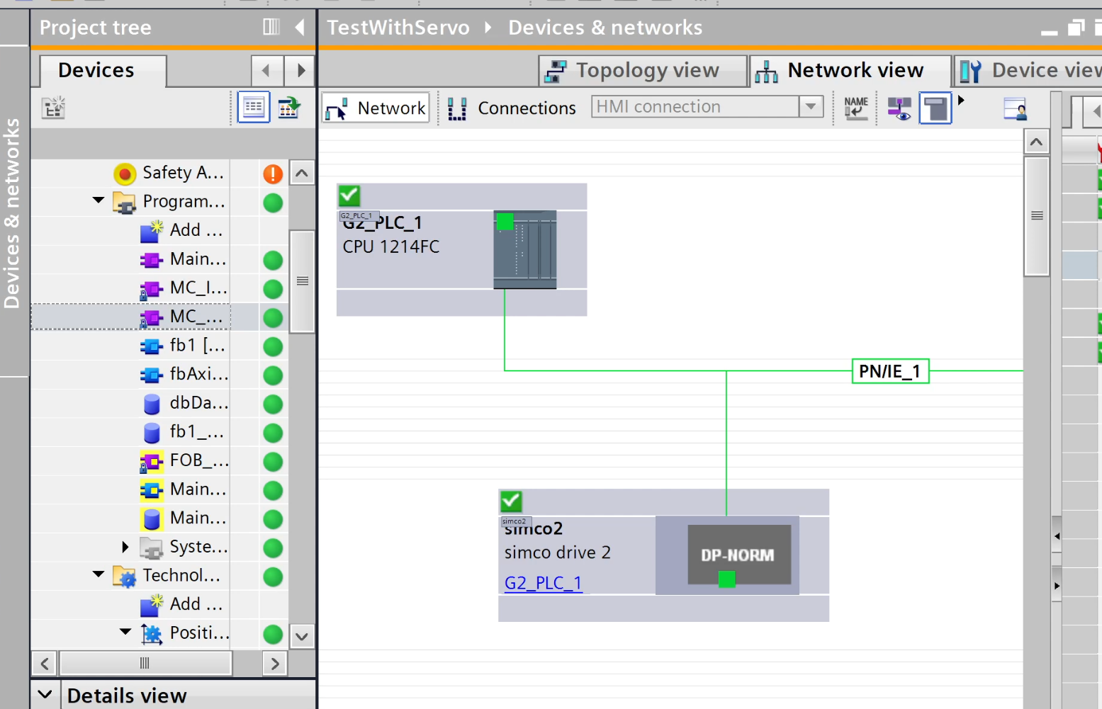
result
Done!PN/IE_1 (G2_PLC_1) and DP-NORM (simco2) are connected by a green wire, indicating that the communication path is established (normally, green wire is a normal connection).
You can check the operation in this video.