In this article, the OMRON NX CPU and SL5700 are used in combination to build an EtherCAT and FSoE network. It also briefly explains the OMRON safety programme concept and how EtherCAT works.
Let’s get started!
Reference Link
Reference Video
OMRON.Let’s Use SL5700 x ECC203 to build EtherCAT/FSoE Network!
About the Hardware
Let’s explain the Omron hardware used in this article.
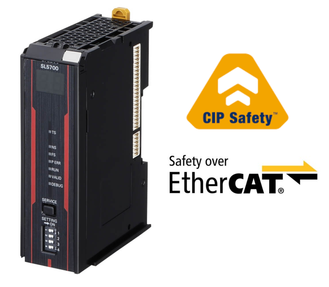
SL-5700
The SL-5700 is a safety controller that can be attached to the NX-CPU, which can be used to create a safety communication network for CIP Safety and FSoe, with up to 254 safety connections and 2032 Safety I/O points.
The SL-5700 also offers 4 MB of memory and SD Card Backup and Restore functions.
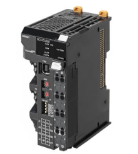
EX-ECC203
The EX-ECC203 is an NX Series EtherCAT coupler with 2 ports and a minimum communication cycle of 125 µs. EX-EC203 can be installed with up to 63 IO Units, up to 10 A current, screwless push-in connectors and hard-wearing end covers. hard-wearing specification with screwless push-in connectors and end covers.
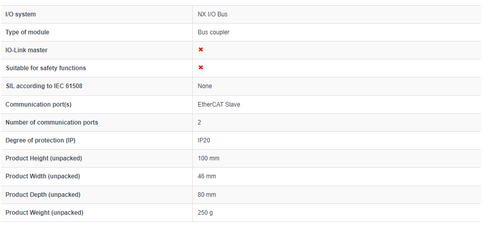
Specification
These are the specifications for EX-ECC203.
EtherCAT?
Before we start this article, a little introduction to EtherCAT: EtherCAT (Ethernet Control Automation Technology) is a high-performance industrial network system based on Ethernet that enables fast and efficient communication.
Each node on the EtherCAT network transmits Ethernet frames at high speed, thus enabling short communication cycle times.。
Although EtherCAT is a proprietary communication protocol, standard Ethernet technology is used for the physical layer. The effectiveness of EtherCAT can be exploited not only in large control systems, where high processing speeds and system integrity are required, but also in small and medium-sized control systems.

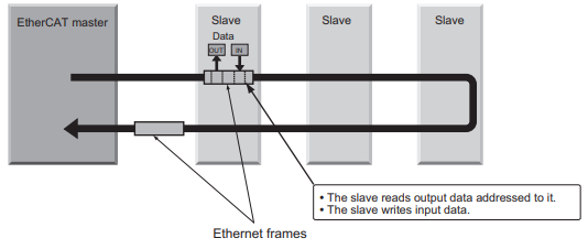
In EtherCAT, Ethernet frames pass through all slave nodes, and when a frame passes through a slave node, the slave node reads and writes the data in the allocated area in the frame in a few nanoseconds.
The last slave sends back all frames, which are then passed through all slaves again and returned to the EtherCAT master. This mechanism guarantees fast, real-time data transmission.
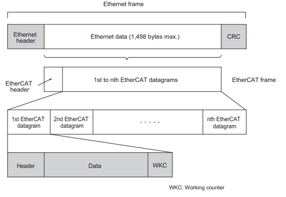
The cyclical data exchange between EtherCAT master and EtherCAT slave uses EtherCAT datagrams, which are stored directly in the Ethernet frame.
Each EtherCAT datagram consists of a header (containing the data length and one or more slave addresses), data and a work counter (check bits).
If you think of an Ethernet frame as a train, EtherCAT datagrams correspond to the cars of the train.
Types of EtherCAT Communications
The following two types of communication are possible with EtherCAT
- PDO communication is performed during each EtherCAT communication cycle and continuously updates the data.
- SDO communication is performed in between PDO communications.
Process Data Communications (PDO Communications)
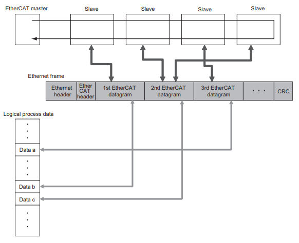
PDO communication processes data cyclically and in real time: the EtherCAT master maps the logical process data space to the nodes and enables cyclic communication between EtherCAT master and slaves.
Process Data Objects (PDOs)
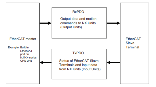
Process Data Objects (PDOs) are used to transfer data in real-time during cyclic communication; RxPDOs are used by EtherCAT Slave Terminals to receive data from the EtherCAT master and TxPDOs are used by EtherCAT Slave Terminals to EtherCAT Slave Terminal to send data to the EtherCAT master.
The EtherCAT application layer can hold several objects to enable the transfer of various process data in the EtherCAT Slave Terminal. The content of the process data is defined in PDO mapping objects; the EtherCAT Slave Terminal supports PDO mapping for I/O control.
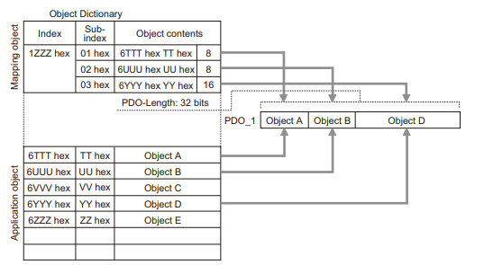
PDO Mapping
The PDO mapping object contains the I/O data of the EtherCAT slave terminal; the PDO mapping object for RxPDO is managed by index 1600-17FF hexadecimal in the Object Dictionary and the PDO mapping object for TxPDO are managed by index 1A00 to 1BFF hexadecimal.
EtherCAT’s PDO mapping scheme is shown below, where three application objects (objects A, B and D) are allocated to a PDO (name: PDO_1) with index 1ZZZZ hexadecimal. Thus, the PDO mapping shows how the application objects are allocated to the PDOs. Indexes and sub-indexes are also assigned to the application object.
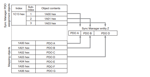
Assigning PDOs
Several PDOs can be assigned to an EtherCAT slave. Here, the PDOs are allocated as 1C12 hex for RxPDO and 1C13 hex for TxPDO. The following example shows how PDOs can be allocated.
In this example, three PDOs (PDO A, PDO B and PDO D) are allocated to index 1C13 hex (for TxPDO). Similarly, one PDO (for RxPDO) is allocated to index 1C12 hexadecimal. These assignments determine which PDOs are used for communication between EtherCAT master and slave.
Mailbox Communications (SDO Communications)
SDO communication is used for message communication. The EtherCAT master sends commands to the slaves and the slaves reply to the EtherCAT master as required in the application.
- Reading and writing process data
- Slave configuration
- Slave status monitoring
Communicatins
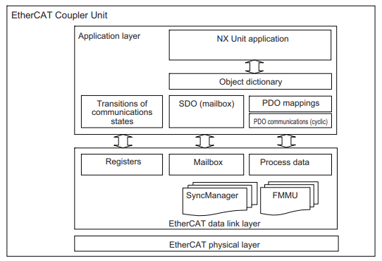
EtherCAT allows the use of several protocols for communication. However, EtherCAT Slave Terminals use the CAN application protocol over EtherCAT (CoE) as device profile for the CAN application protocol. CoE is a communication interface designed to provide compatibility with EtherCAT devices.
The CAN application protocol is an open network standard. The figure below shows the structure of the CoE of an EtherCAT Coupler Unit.
Network Topology
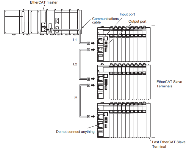
Cable connections can be made freely within the EtherCAT network.
The following example shows an Example connection.
Connect the communication cable from the EtherCAT master to the input port of the first EtherCAT slave terminal, and then connect another communication cable from the output port of the first EtherCAT slave terminal to the input port of the next EtherCAT slave terminal.
Note that nothing should be connected to the EtherCAT slave terminal output port at the network termination.
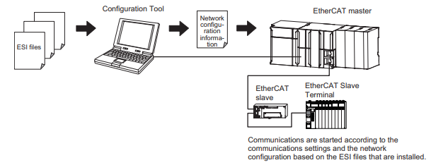
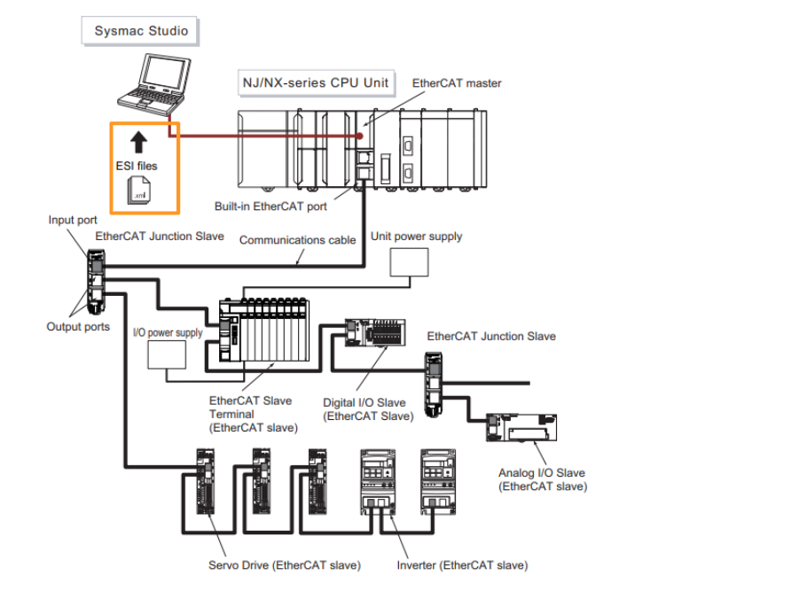
EtherCAT Slave Information Files(ESI Files)
The configuration information of the EtherCAT slaves is provided in ESI files (EtherCAT Slave Information), where the EtherCAT communication settings are defined based on the ESI files of the connected slaves.
The network connection information, which can be installed in the network configuration software, The network configuration information can be created by installing it in the network configuration software.
Note that when using Sysmac Studio and an OMRON device, it is not necessary to install the ESI file; Sysmac Studio already has the ESI file for OMRON EtherCAT slaves installed.
You can also update Sysmac Studio to get the latest model ESI files.
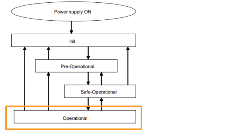
Transitions of Communications States
The state transition model of the communication control of an EtherCAT slave terminal is controlled by the EtherCAT master. The communication state transition from power on is shown in the figure below.
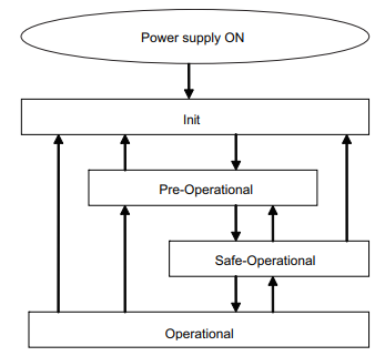
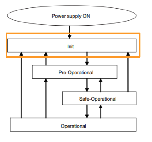
Init
Communication is initializing. Communication is not possible.
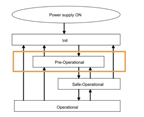
Pre-Operational
In this state, only SDO communication (message communication) is possible.
When initialization is complete, this state is used to initialize network settings.
Safe-Operational
In this state, both SDO communication (message communication) and PDO transmission are possible.Status and other information is sent from the slave terminal.
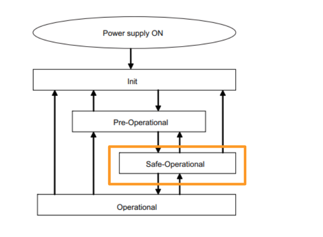
Operational
This is the normal state of communication, and PDO communication is used to control I/O data.
Communications between an EtherCAT Master and Slaves
Free-Run Mode
In this mode, the slave processes I/O asynchronously to the master’s communication cycle.
DC Mode
In this mode, the slave processes I/O synchronously with the master’s communication cycles (i.e., refreshes I/O data). In this mode, a mechanism called distributed clock (DC) is used to synchronize EtherCAT communications.
The clock is shared by the master and slaves, and in DC mode the master and slaves synchronize by sharing the same clock. Interrupts (Sync0) are generated to the slaves at precise intervals based on this clock, and each slave performs I/O operations at this precise timing.
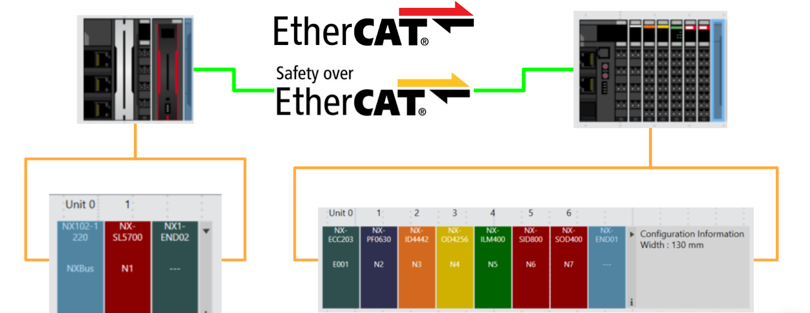
System Configuration
This figure shows an example of an EtherCAT Network system.
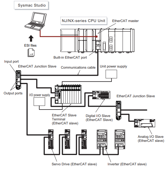
Master
The EtherCAT master manages the network, monitors slave states and exchanges I/O data.
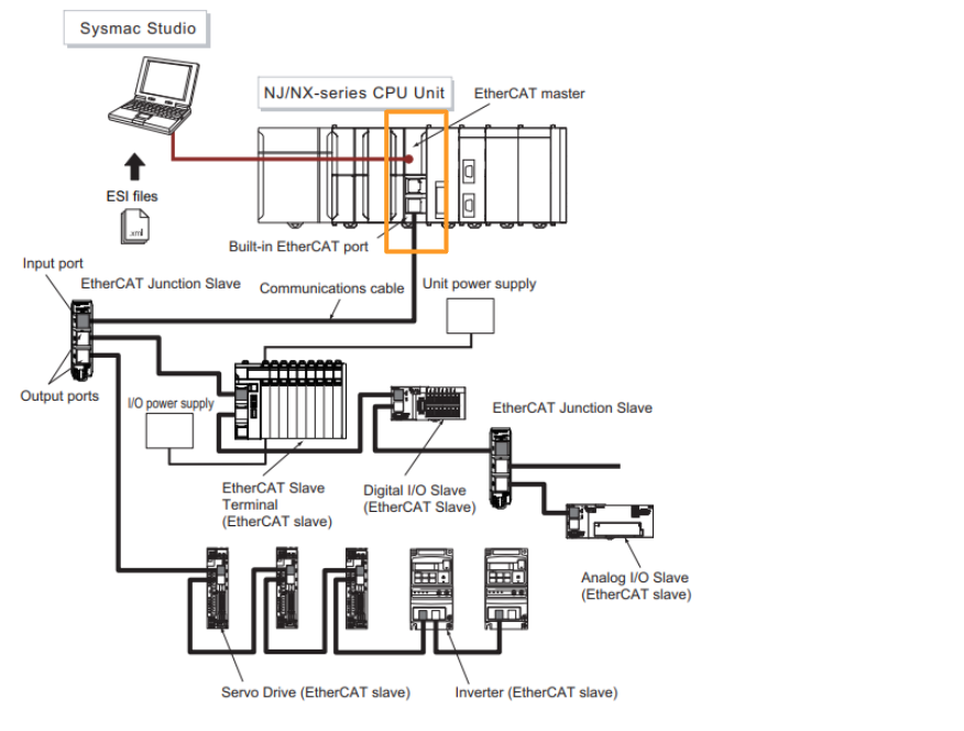
Slave
The EtherCAT slave outputs the output data received from the EtherCAT master via the EtherCAT network. It also sends input data to the EtherCAT master via the EtherCAT network.
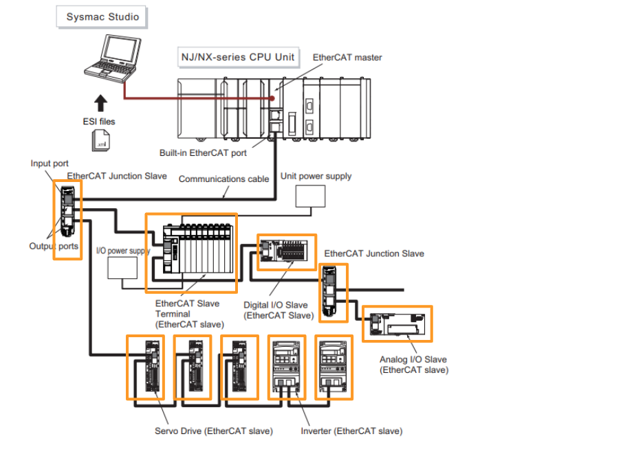
EtherCAT Slave Terminals
An EtherCAT Slave Terminal is a Block Slave consisting of an NX Unit mounted on an EtherCAT Coupler Unit.
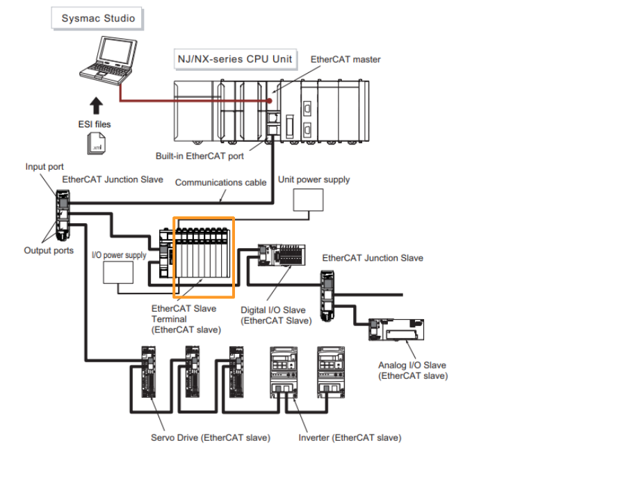
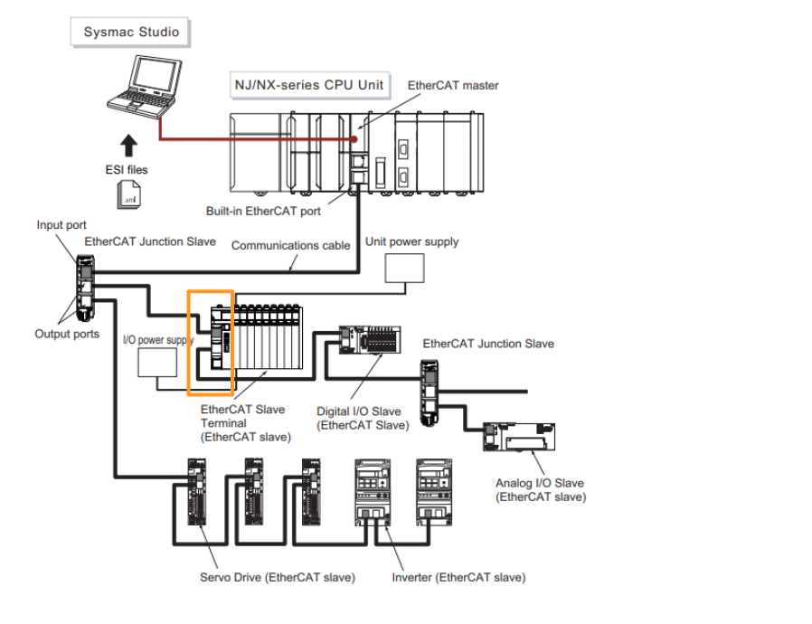
EtherCAT Coupler Units
The EtherCAT Coupler Unit is a communication coupler unit that connects the NX Units to the EtherCAT network.
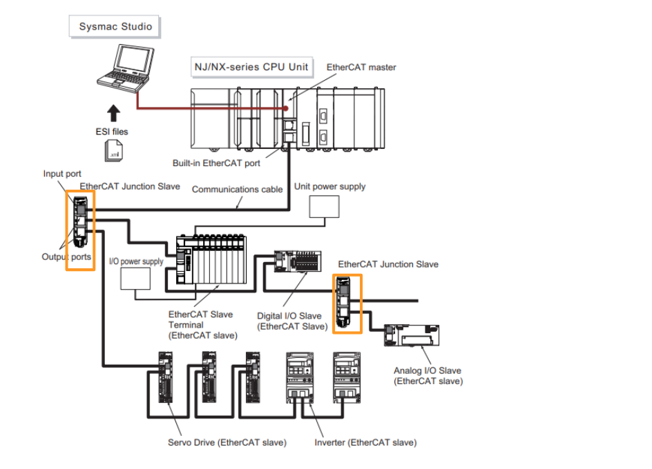
EtherCAT Junction Slaves
Junction slaves are only used for branching EtherCAT network wiring.
Sysmac Studio
Sysmac Studio runs on a PC and is used for configuration, programming, monitoring and troubleshooting of EtherCAT networks and slaves.
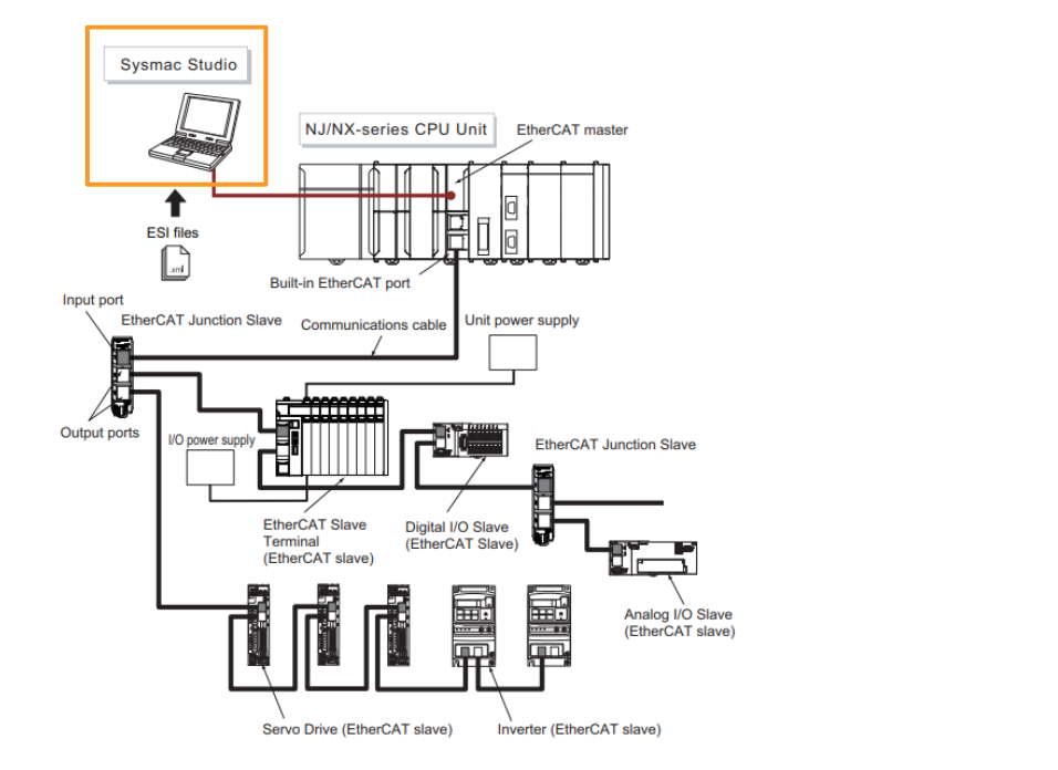
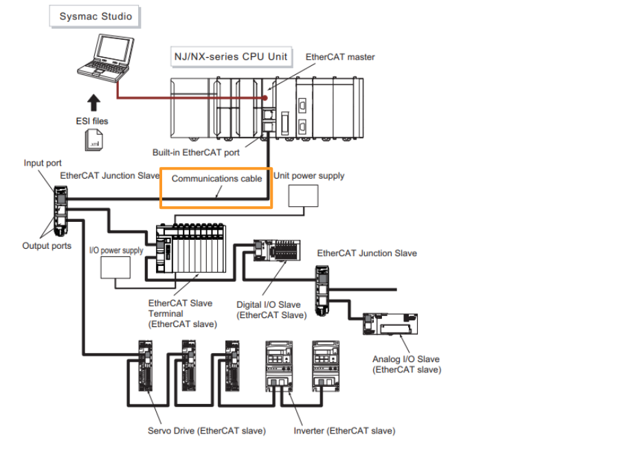
Communications Cables
Use double-shielded cables with aluminum tape and braid of Ethernet Category 5 (100BASE-TX) or higher, and use straight wiring.
ESI (EtherCAT Slave Information) Files
The ESI file contains EtherCAT slave-specific information in XML format.
Hardware Switch Settings
EX-ECC203 has two physical switches and can be configured with EtherCAT Slave addresses.
Rotary Switches
The rotary switch sets the node address of the EtherCAT slave terminal on the EtherCAT network. The node address is set by the tenth and first digits of the decimal number; the 100s digit is set by pin 4 of the DIP switch, which is described below. The setting range is 00 to 99 (factory default is 00).
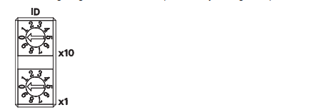
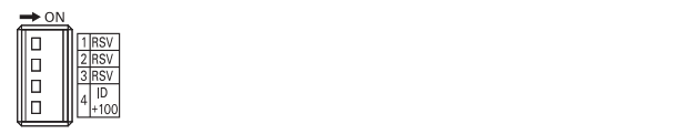
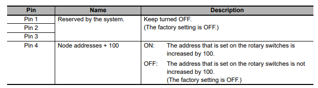
DIP Switch
When pin 4 of the DIP switch is turned ON, 100 is added to the node address set by the rotary switch. The other pins are reserved by the system.
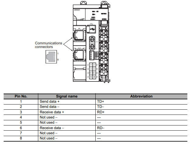
Communication Connectors
This is the Connection Connector for EX-ECC203 EtheCAT Coupler.
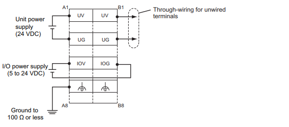
Power Supply
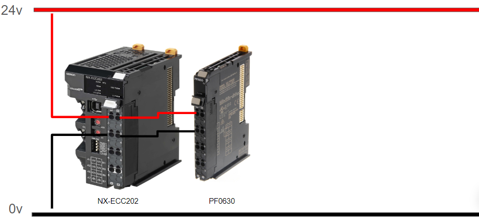
The wiring for power and ground to the EtherCAT coupler unit is shown in the figure below.
Settings and Setting Procedures
The settings for accessing I/O data of an EtherCAT slave terminal from an NJ/NX-series CPU unit are shown below.
We can configure the EtherCAT Coupler Unit as an EtherCAT slave, set up the slave terminal and configure its operation. Variable Assignment Assign and register variables required to access I/O data from the user program and program them to suit the application.

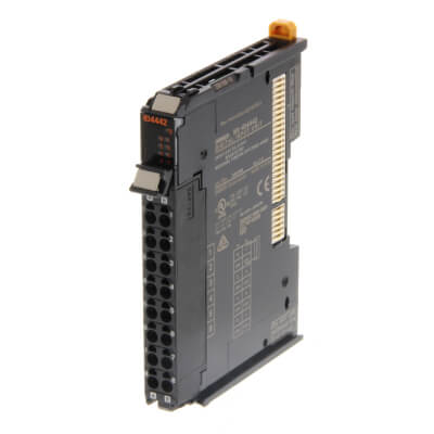
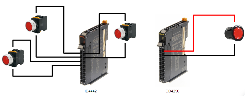
ID4442?
The ID4442 is an input module with 8 digital inputs, standard speed, PNP 24 VDC, screwless push-in connector, 12 mm wide.
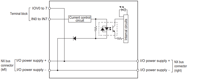
Wiring
This is an example of ID4442 wiring.
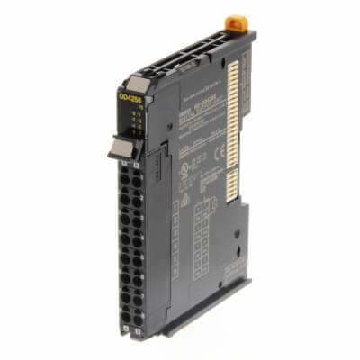
OD4256?
The OD4256 is an 8 digital output, standard speed, PNP 24 VDC, 0.5 A/point, 4 A/NX unit, screwless push-in connector, 12 mm wide output module.
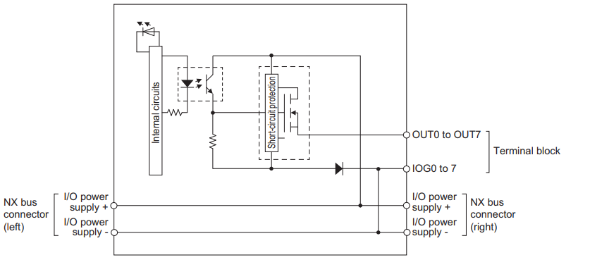
Wiring
This is a wiring example of OD4256.
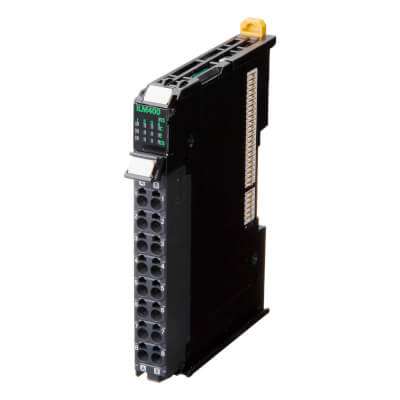
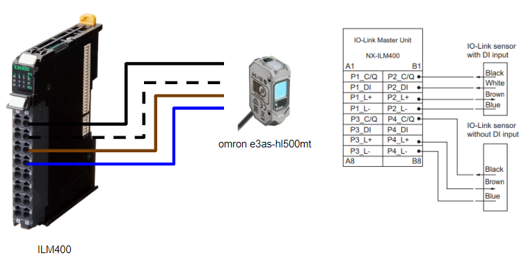
ILM400?
ILM400 is an IP20 module with 4 channels of NX Series IO-Link Master.
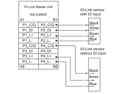
Wiring
This is an example of ILM400 wiring.
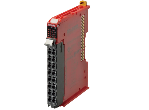
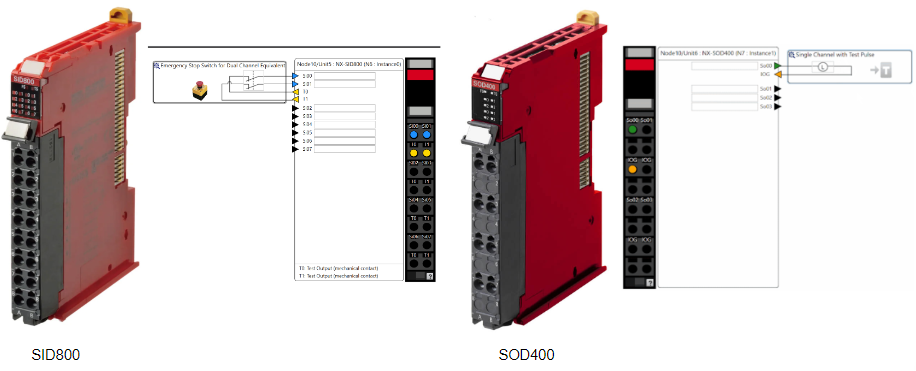
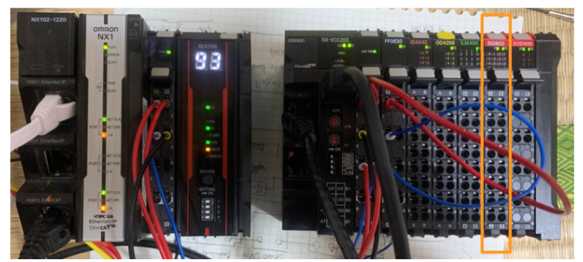
SID800?
SID800 is an NX series safety input, a module with eight safety inputs and two test outputs.
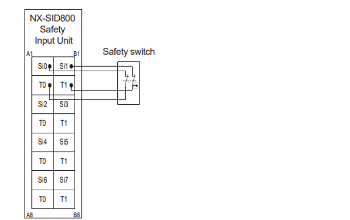
Wiring
Here is the wiring for the SID800: Si0-Si7 are the safety input pins, and T0 and T1 are the test output pins.
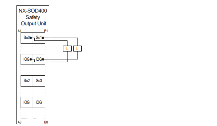
SOD400?
SOD400 is an NX series safety output module with four safety outputs.
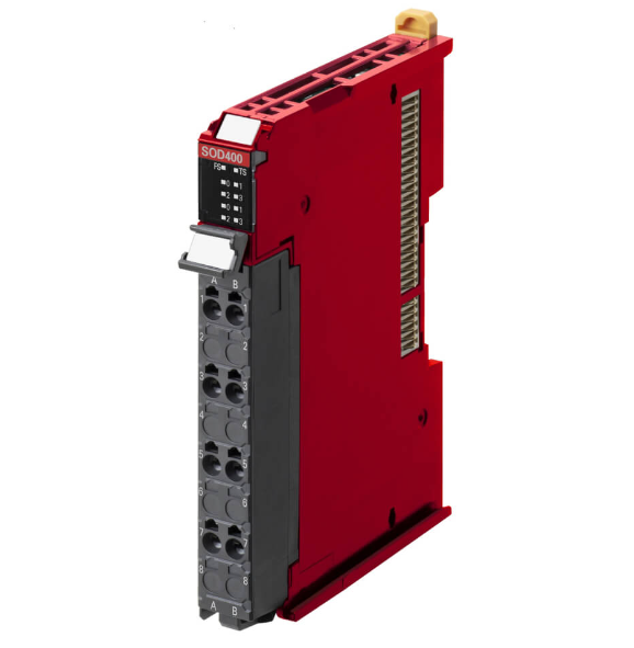
Wiring
This is SOD800 wiring.
Safety PLC Programming Rules
The Safety Control Unit has the following function types
Standard functions・Standard Function Block
These Functions/Function Blocks do not use safety data.
- Program Execution Control Instructions
- Data Type Conversion Instructions
- Logical Operation Instructions
- Calculation Instructions
- Timers
- Counter
etc..
Safety standard function blocks
These Functions/Function Blocks use safety data.
- Emergency Stop Order
- Door lock order
etc..
Safety FB
The default for all SAFEBOOL signals is FALSE (i.e. safe state).
These definitions reflect the functionality of the IEC 61131 standard. For example, if it occurs, all outputs change to FALSE, as defined in the default signaling rules.
All outputs are also refreshed every safety task period.
Safety FB Common Input Variables
Activat‐BOOL
Enables or disables the FB. Its parameters can be entered as variables or constants and default to FALSE. Normally, enter a TRUE constant to enable FB.
S_StartReset‐SAFEBOOL
Safety Controls automatic and manual resetting at FB start-up (start of programme execution). Variables or constants can be entered.
- FALSE (default): manually performs a reset when the safe CPU unit is started.
- TRUE: Automatically performs a reset when the safe CPU unit is started.
S_AutoReset‐SAFEBOOL
It controls the automatic and manual resetting of the emergency stop button operation. Its parameters can be entered as variables or constants.
- FALSE (default): performs a manual reset when the emergency stop button is released.
- TRUE: Automatically performs a reset when the emergency stop button is released.
Reset‐BOOL
This parameter is an operation that resets the Sfaety FB, but is used for different purposes by different FBs.
Safety FB Common Output Variables
Ready‐BOOL
Indicates that the FB is inactive and the programme will not be executed. This is useful for activating/deactivating DEBUG mode or additional FBs or for further processing of the functional programme.
Error‐BOOL
Indicates that no errors have occurred; the status of the FB is given by DiagCode.
DiagCode‐WORD
All statuses (active, non-active, error) of the FB are stored in this variable. The information is given in hexadecimal. Only one code is given each time. If more than one error occurs, the information of the first error detected is output to DiagCode.
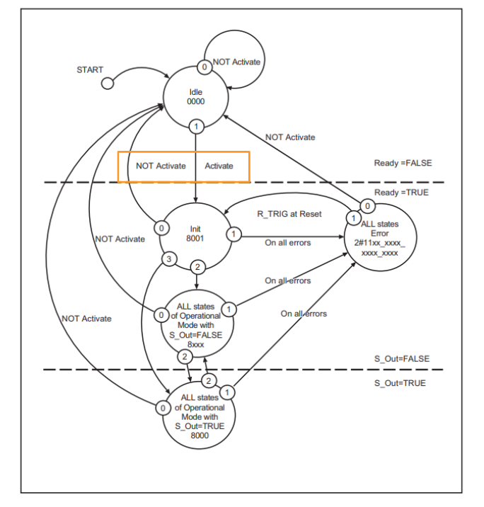
Safety FB Common State Transition Diagram
The following type of state transition diagram shows the changes in the state of a safety FB. They apply to all safety FBs, but some transitions are special to some FBs and are not shown here.
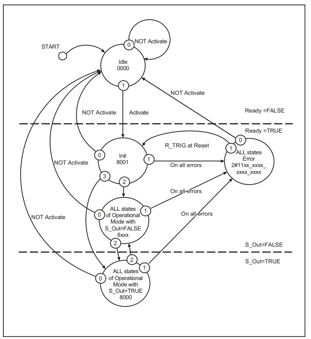
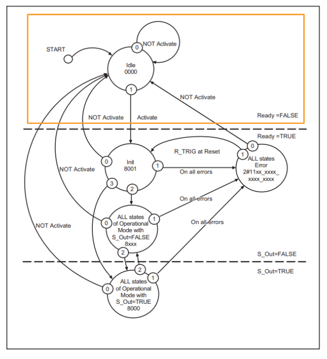
This diagram is divided into three parts. In the top part, the FB is not operating and is in a safe state (safety output is FALSE).
In the middle section, the FB is in operation and in a safe state (safety output is FALSE).
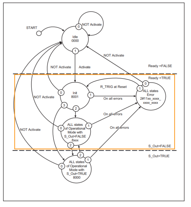
At the bottom, the FB is operating normally (safety output is TRUE).
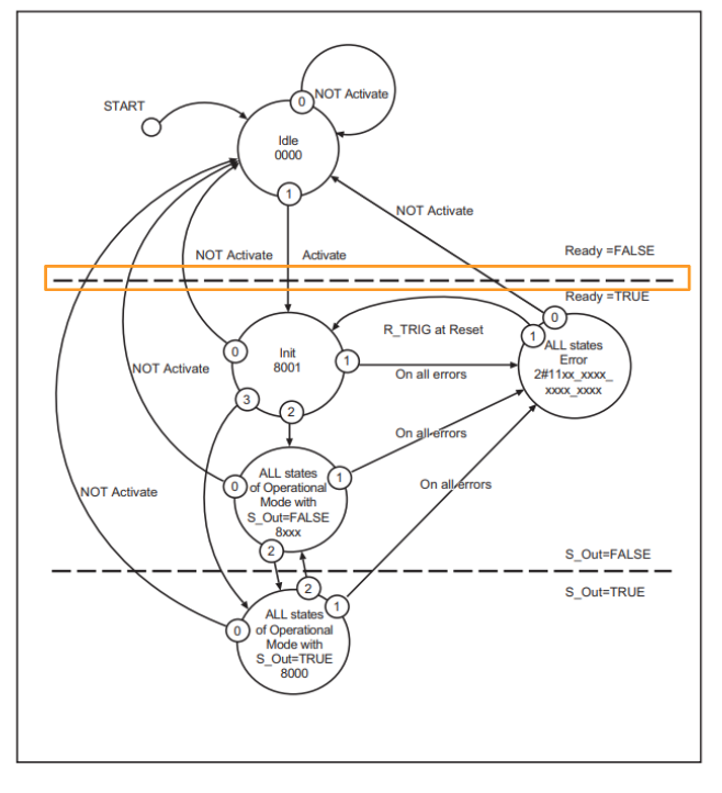
The dotted line at the top of the state transition diagram indicates the transition from inactive to active.
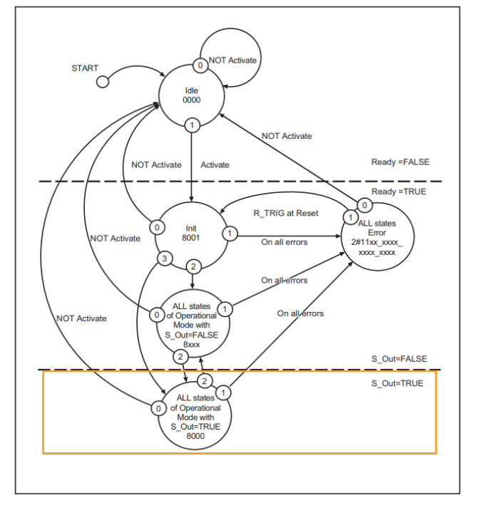
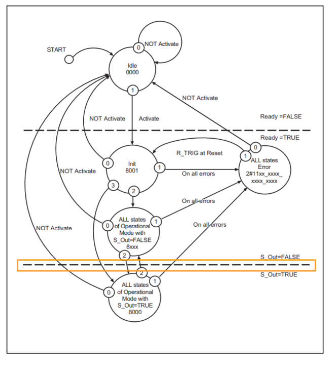
The dotted line at the bottom of the diagram shows the transition from the safe state to the normal state of the FB.
The priority of the state transition is indicated by a number, with the highest priority being 0.
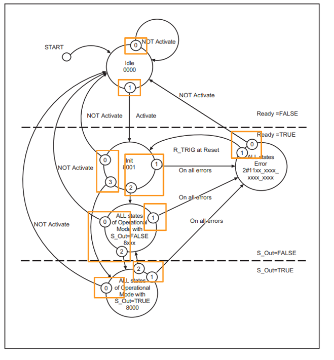
The status roundels show the status name and the hexadecimal value of the DiagCode.
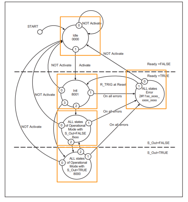
OR, AND and XOR are used as logical operators to perform state transitions.
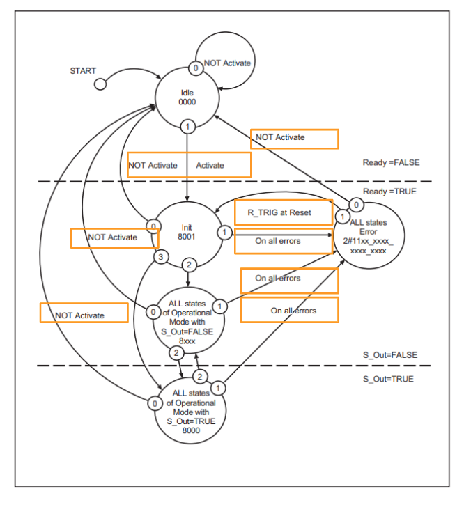
In the FB, the start-up state is the Idle state, which is the first time the FB changes to an operational state.
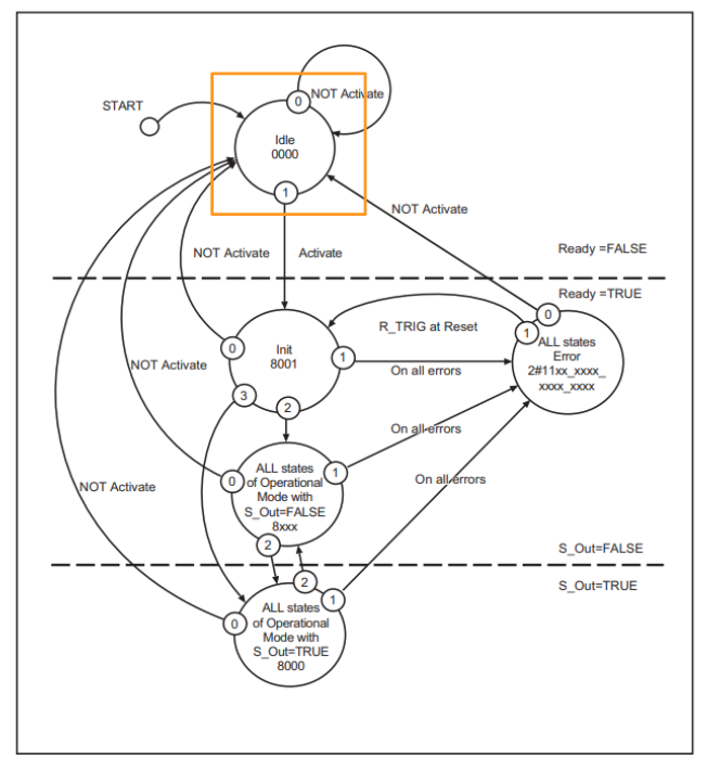
Changing Activate to FALSE allows the user to enter the Idle state from any other state; if Activate is FALSE, operation 0 has top priority.
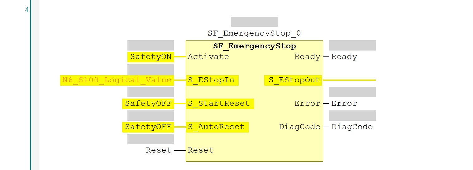
SF_EmergencyStop
This Safety FB can monitor the input from the emergency stop button.
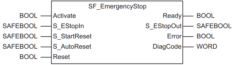
VAR_INPUT
| Variable Name | Type | Description |
| Activate | BOOL | Refer to the Safety FB Common Input Variables mentioned earlier. |
| S_EStopIn | SAFEBOOL | Emergency stop signal. |
| S_StartReset | SAFEBOOL | Refer to the Safety FB Common Input Variables mentioned earlier. |
| S_AutoReset | SAFEBOOL | Refer to the Safety FB Common Input Variables mentioned earlier. |
| Reset | BOOL | Refer to the Safety FB Common Input Variables mentioned earlier. |
VAR_OUTPUT
| Variable Name | Type | Description |
| Ready | BOOL | Refer to the Safety FB Common Input Variables mentioned earlier. |
| S_EStopOut | SAFEBOOL | Indicates the state in which the safety function is activated.TRUE: Safety outputs are active. |
| Error | BOOL | Refer to the Safety FB Common Input Variables mentioned earlier. |
| DiagCode | WORD | Refer to the Safety FB Common Input Variables mentioned earlier. |
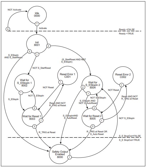
State Transition Diagram
This is the state transition diagram for SF_EmergencyStop.
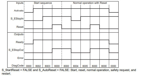
TimeChart‐S_Start=False,S_AutoReset=False
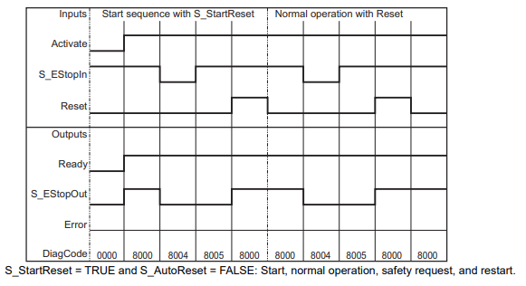
TimeChart‐S_Start=True,S_AutoReset=False
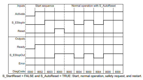
TimeChart‐S_Start=False,S_AutoReset=True
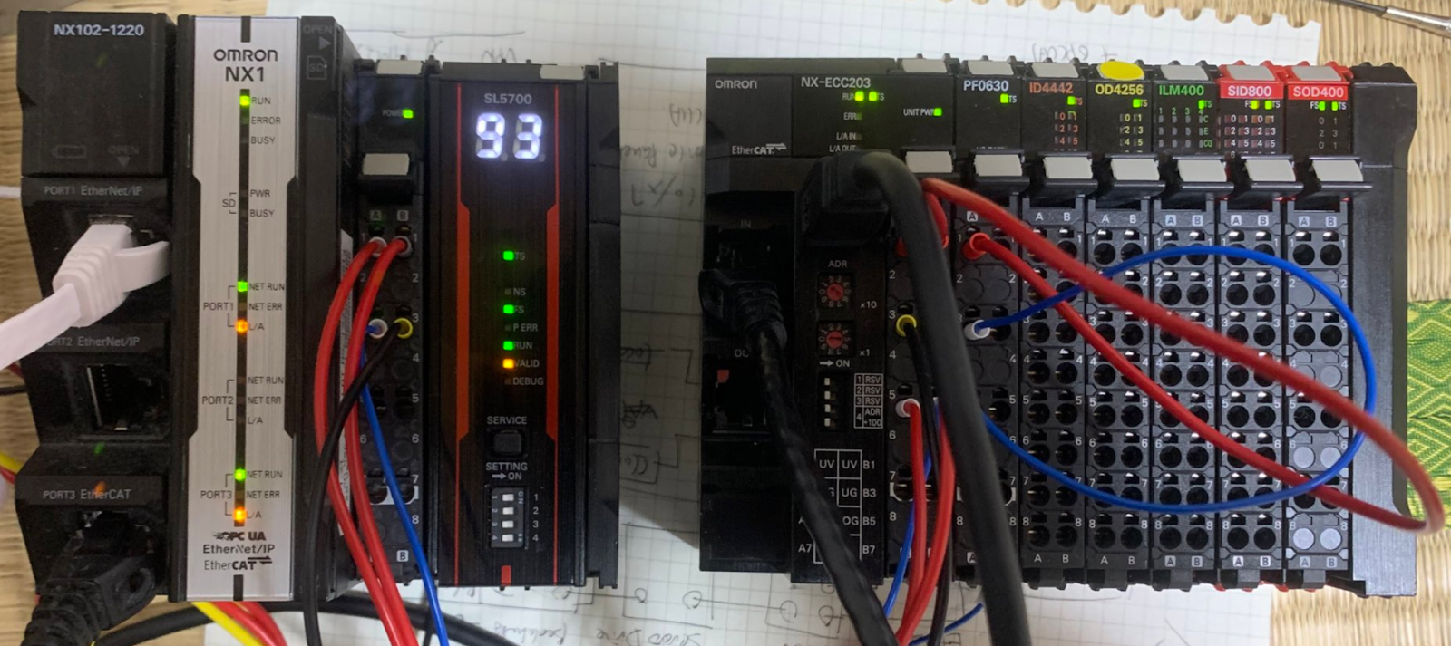
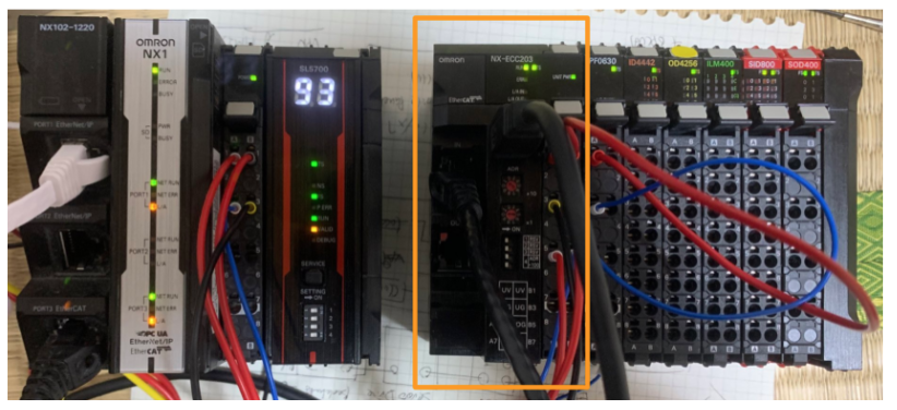
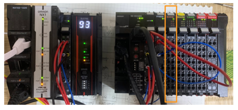
Implementation
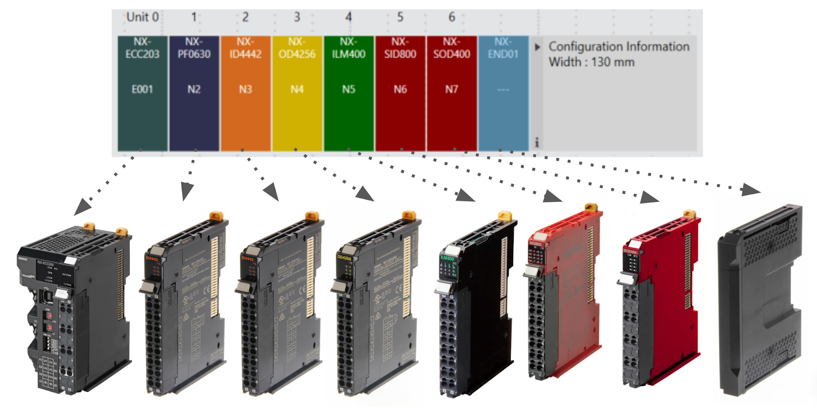
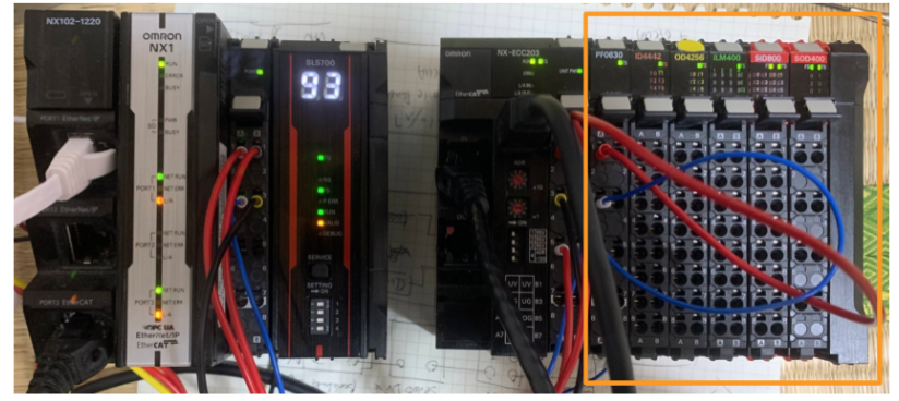
This is the Configuration for this Tutorial.
Wiring
NX-ECC202, PF0630
ID4442,OD4256
ILM400
SID800,SOD400
EtherCAT Configuration
We will now build the EtherCAT Hardware in Sysmac Studio.
Add Terminal Coupler
Add EtherCAT Coupler NX-ECC203.
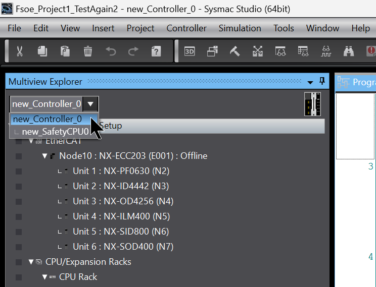
Click on ‘EtherCAT’ in the Sysmac Studio.
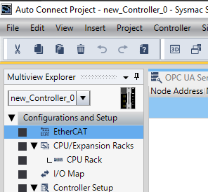
Select Terminal Coupler from the ToolBox > Add the NX-ECC203 to the EtherCAT network.
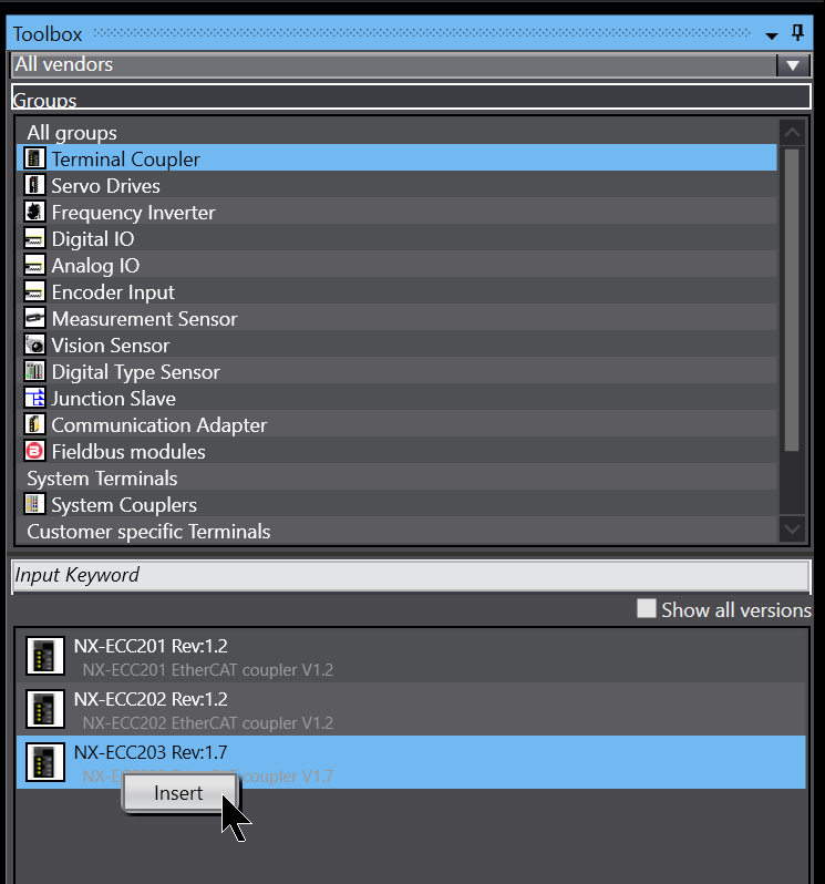
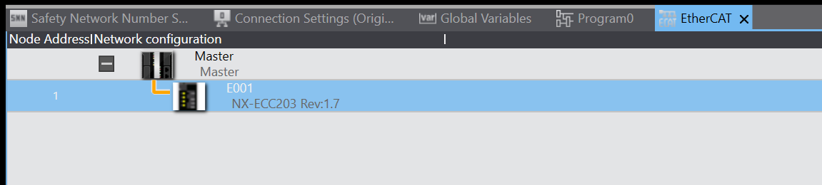
Done!
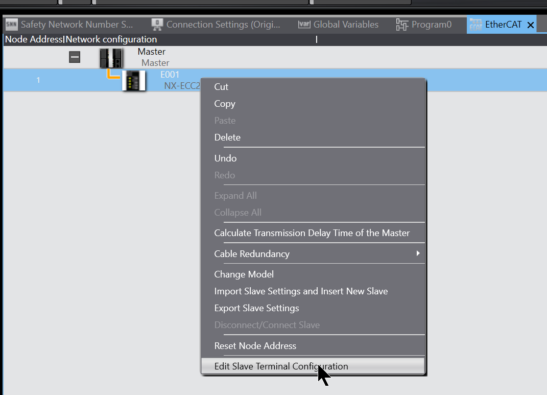
Slave Terminal Configuration
Now add each Slave Terminal installed on the NX-ECC203 to the project.
Right-click the NX-ECC203 you have just added and click >Edit Slave Terminal Configuration.
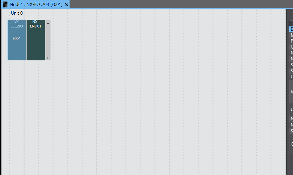
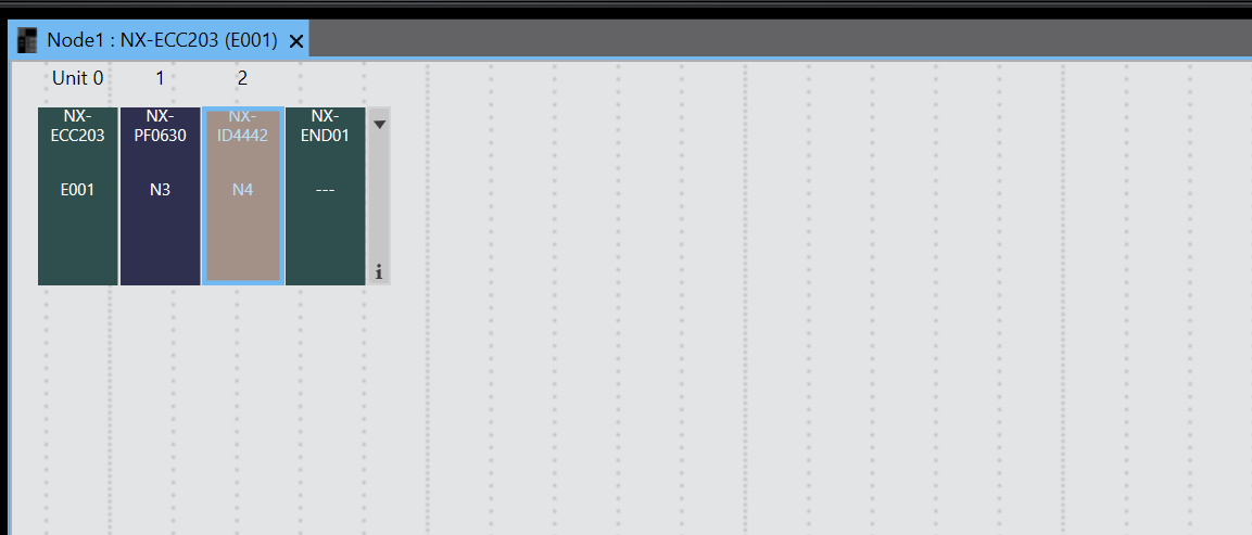
This is the NX-ECC203 settings screen.
Insert NX-PF0630
Add the power supply module NX-PF0630 in the first slot to Hardware Configuration.
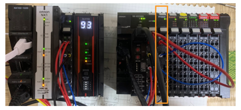
Select NX-PD0630 Ver 1.0 from the Toolbox > Right-click and click Insert.
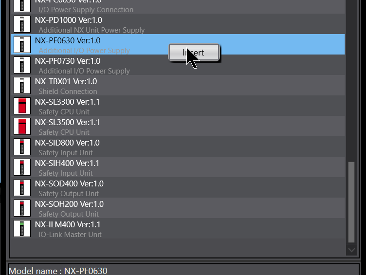
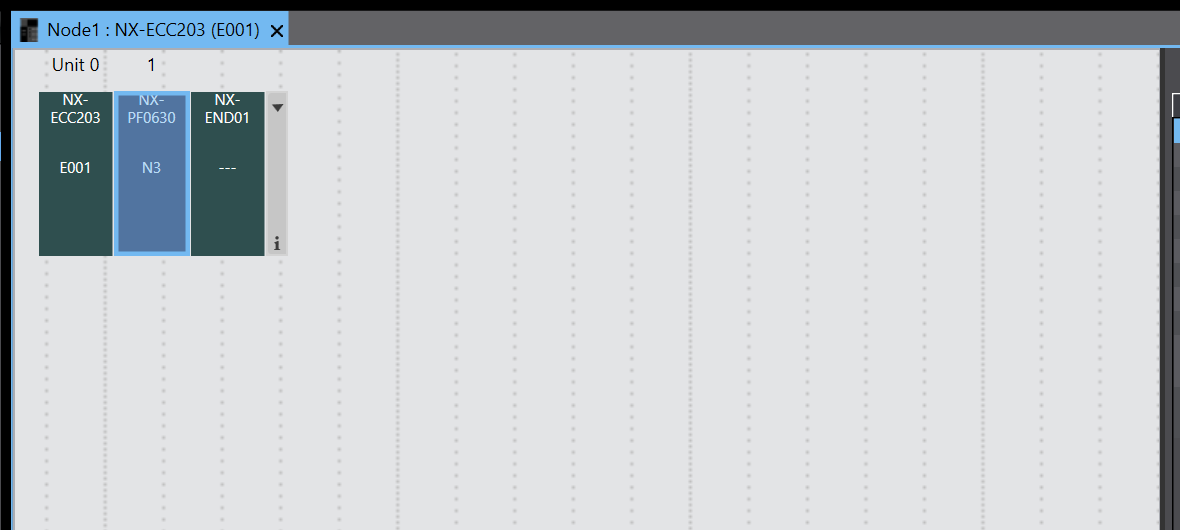
Done!NX-PF0630 has been added to Slot 1.
Insert NX-ID4442
Add the second slot input module NX-ID4442 to the Hardware Configuration.
Select NX-ID4442 Ver 1.0 from the Toolbox > right-click and click Insert.
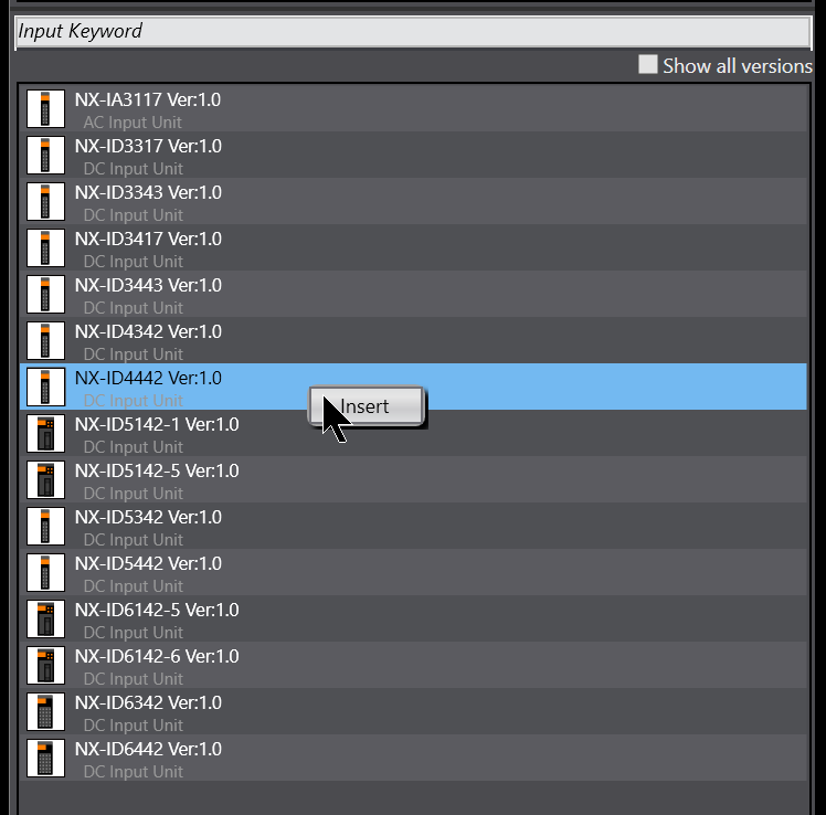
Done!NX-ID4442 has been added to Slot 2.
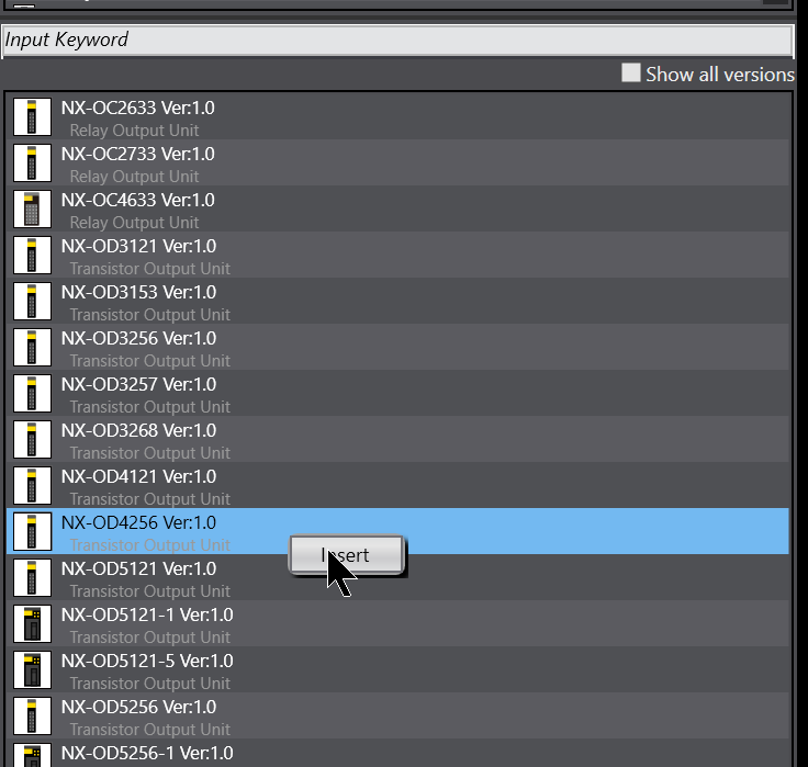
Insert NX-OD4256
Add the third slot output module NX-OD4256 to Hardware Configuration.
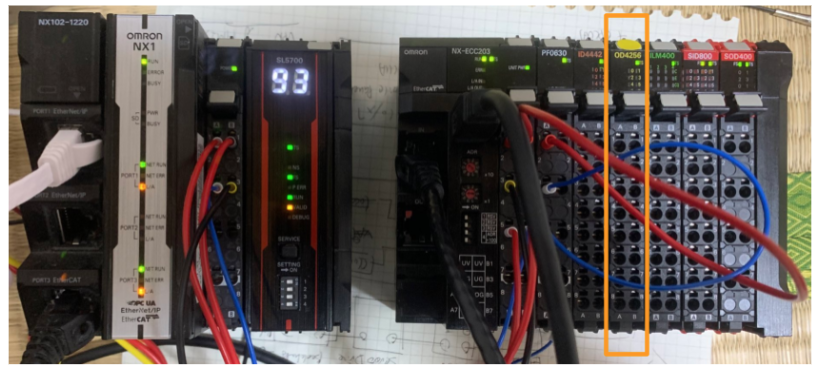
Select NX-OD4256 Ver 1.0 from the Toolbox > right-click and click Insert to add it.
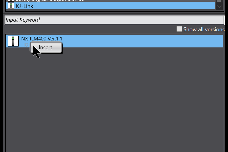
Insert NX-ILM400
Add the fourth slot IO-LINK module NX-ILM400 to Hardware Configuration.
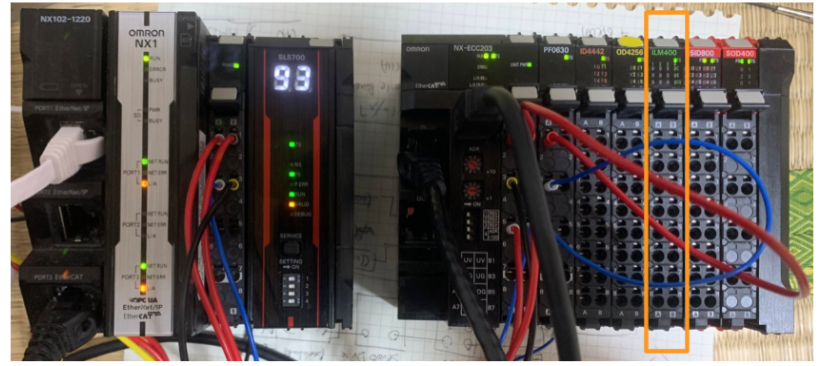
Select NX-ILM400 Ver1.1 from the Toolbox > right-click and click Insert to add it.
Note that the module version must also match the actual device.
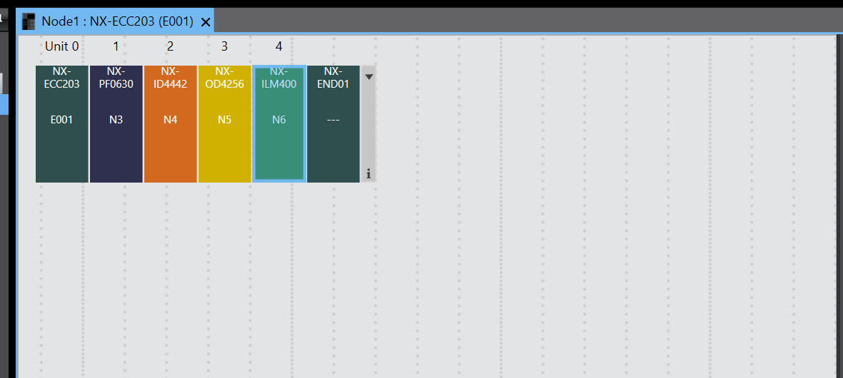
Done!NX-ILM400 has been added to Slot 4.
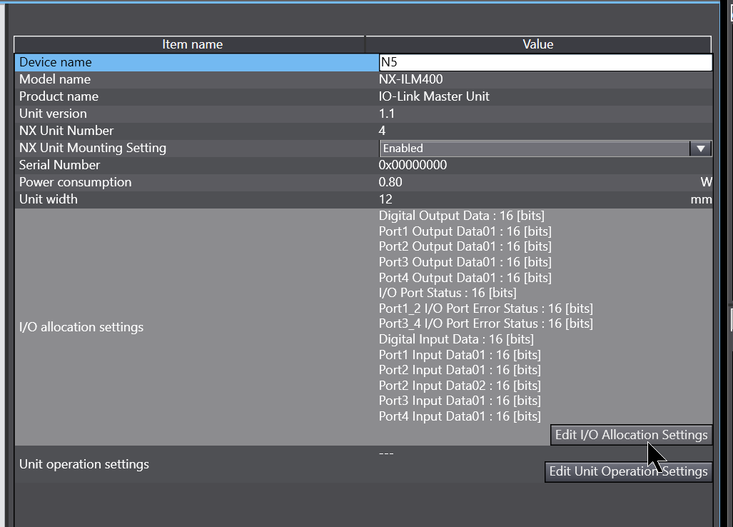
Configuration
As the ILM400 is an IO-LINK module, it needs to be configured in more detail, so when you click on ILM400, the detailed settings for the corresponding module are displayed on the right-hand side of the Sysmac Studio.
Now we need to configure the Unit Operation Settings.
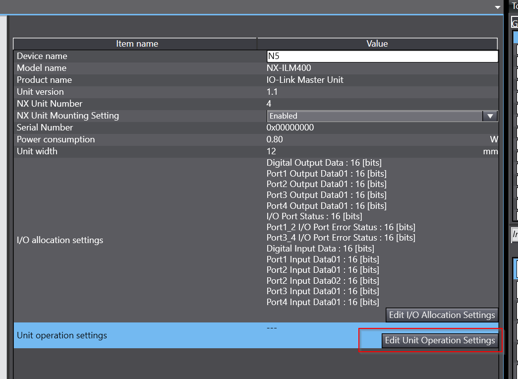
All configuration items for the relevant module are displayed.
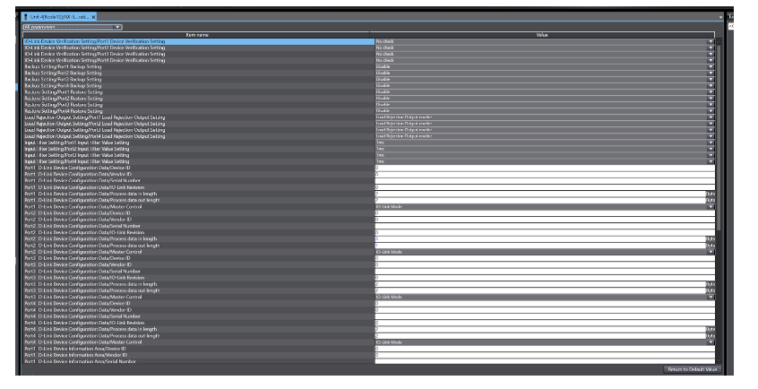
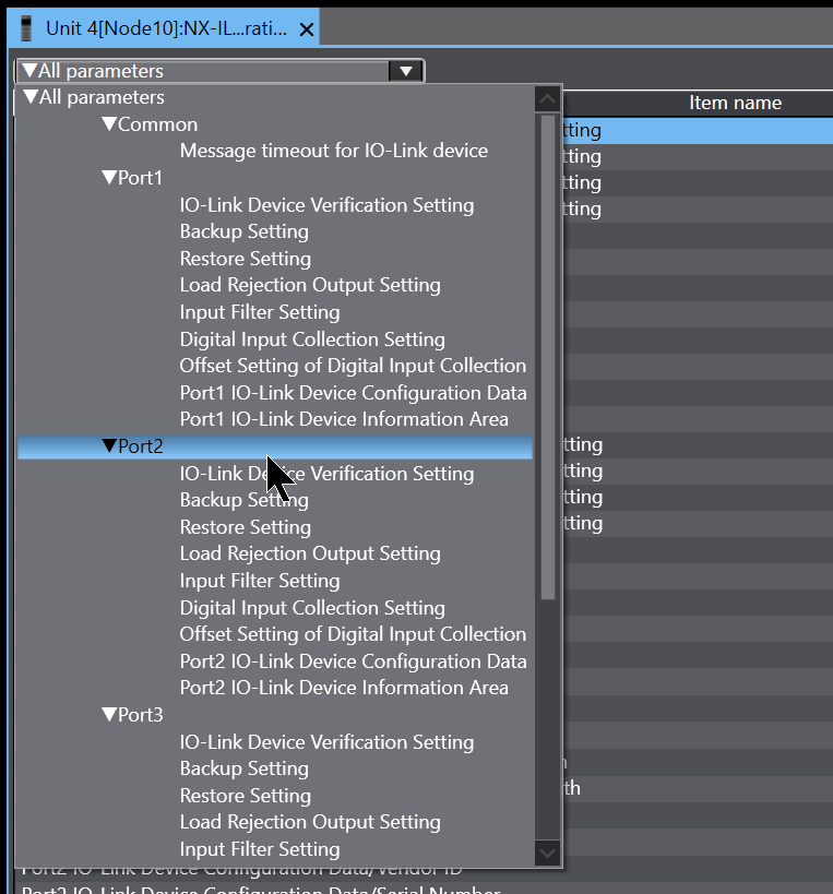
You can filter out items that are not configured from the Drop-List in All Parameters.
In this case, only Port 2 is connected to the IO-LINK device, so select Port 2.
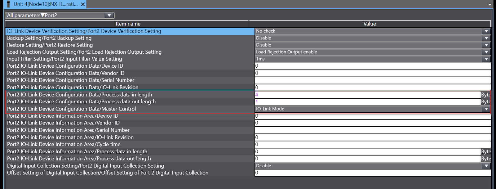
Sysmac Studio only appears in the Port2 configuration section of the ILM400 and Process Input Data and Process Output Data should be set to match the IO-LINK device.
The IO-LINK device used in this article has a 4 Bytes input and 1 Byte output, so set Process data in length to 4 Bytes and Process data Output Length to 1 Byte.
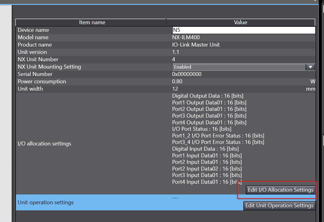
Now click on ‘Edit I/O AllcationSettings’ to change the Data Mapping of the ILM400.
This is the Process Data Mapping screen for each Port.
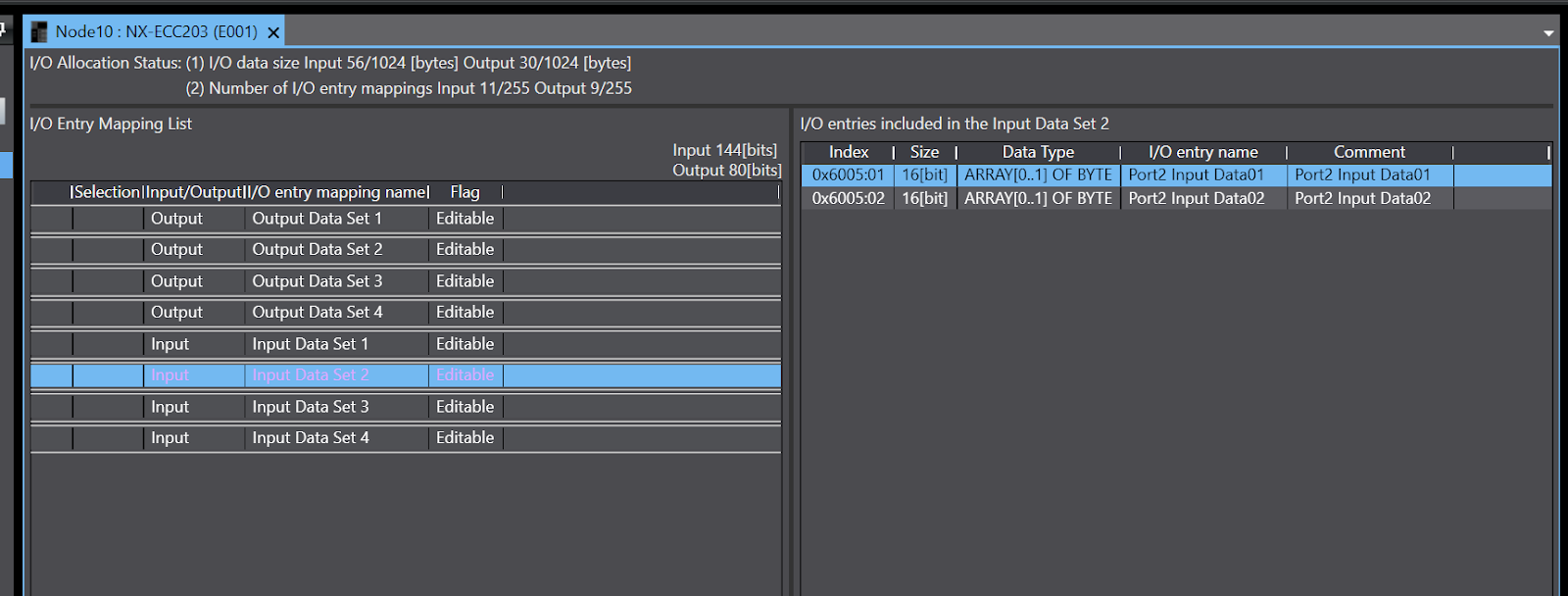
In this case, the input data for Port 2 is 4 Bytes, but only 2 Bytes on Default, so a small change is required: select Port 2 in Input > click Add I/O Entry on the right.
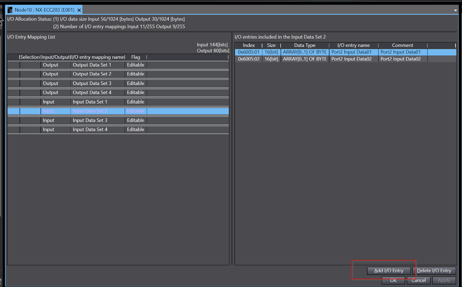
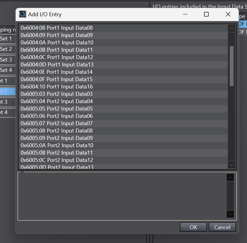
Display all the I/O Entries that have been added to the ILM400 and add Port2 Input Data02.
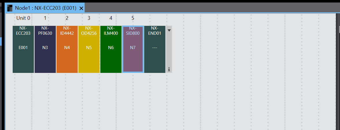
Insert NX‐SID800
Add the fifth slot safety input module NX-SID800 to Hardware Configuration.
Select NX-SID800 Ver 1.0 from the Toolbox > right-click and click Insert to add it.
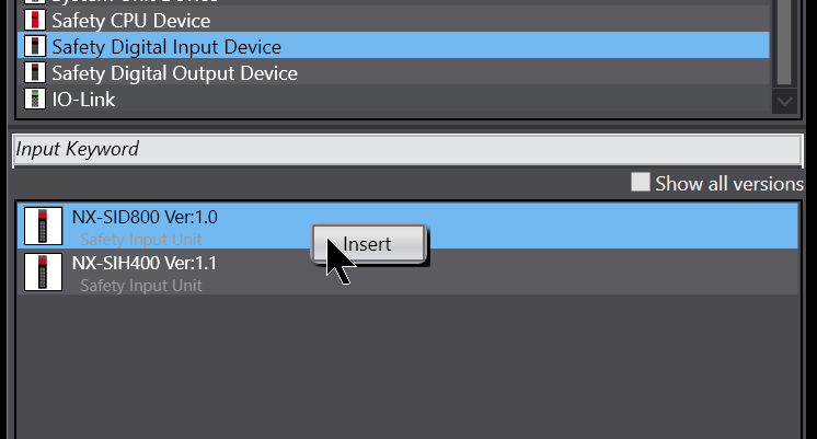
Done!NX-SID800 has been added to Slot 5.
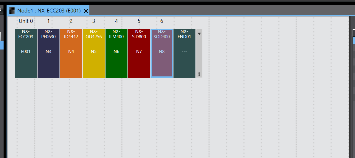
Insert NX‐SOD400
Add the sixth slot safety output module NX-SOD400 to Hardware Configuration.

Select NX-SOD400 Ver1.0 from the Toolbox > right-click and click Insert to add it.
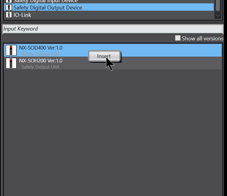
Done!NX-SDO4000 has been added to Slot 6.
Safety Controller Configuration
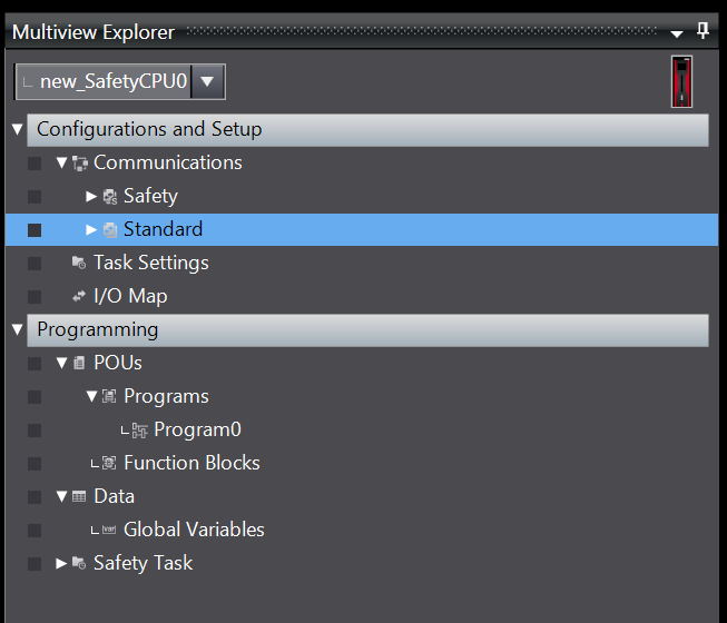
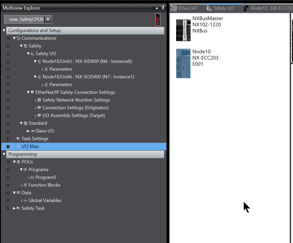
Select Safety Controller from Multview Explorer to build the Safety Controller.
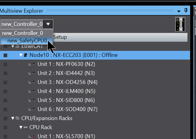
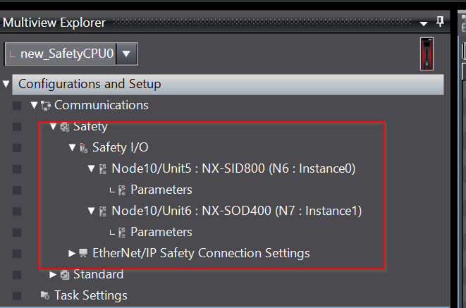
This is the Safety Controller build screen.
There are safety input and safety output modules added earlier from the Safety I/O section.
Safety Input
To build the safety input module, click on the Parameters item under Node10/Unit5.
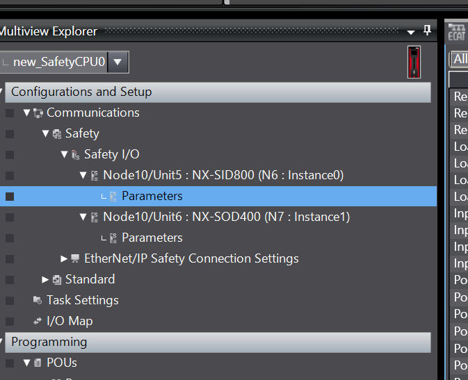
This is the safety module configuration screen.
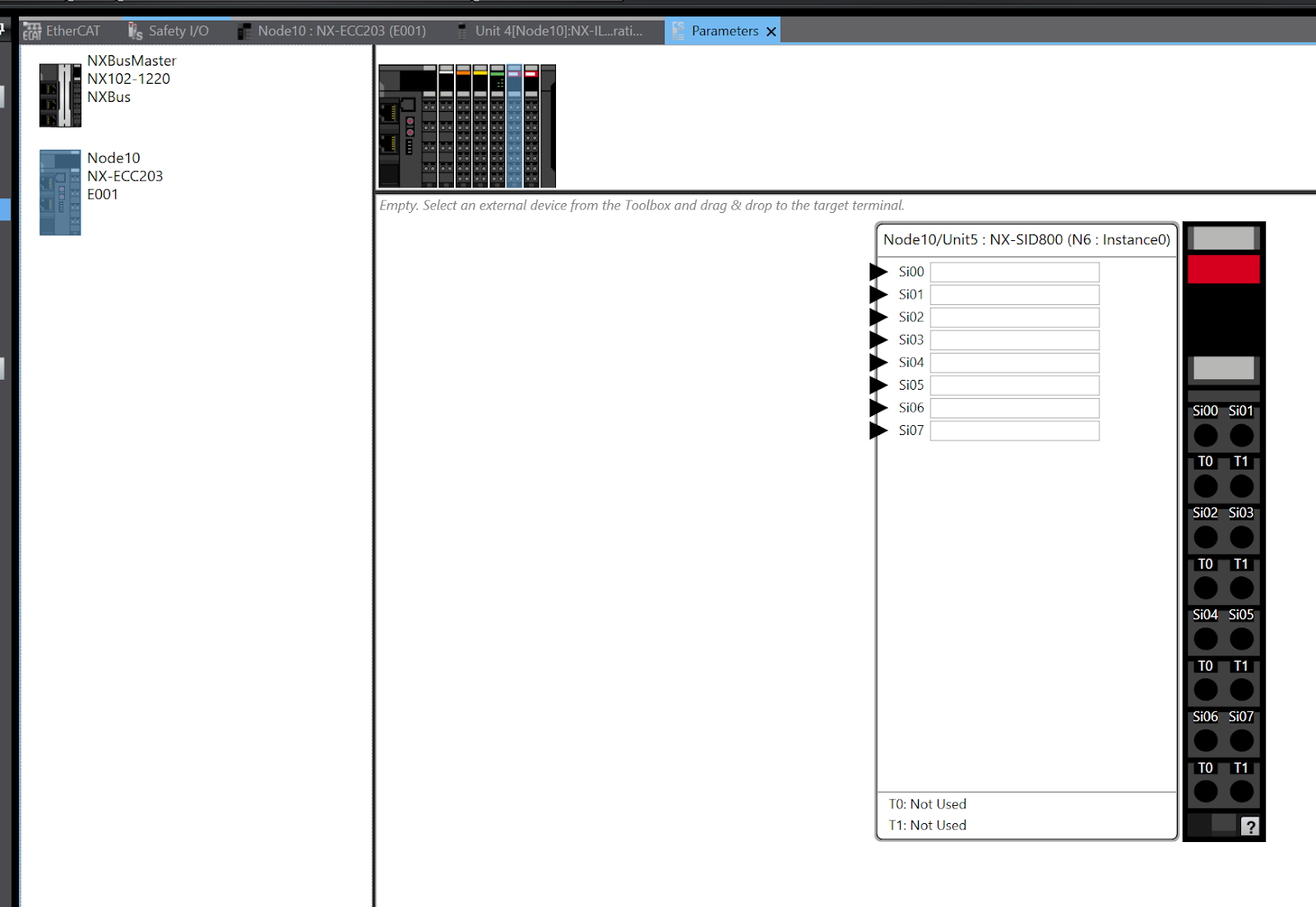
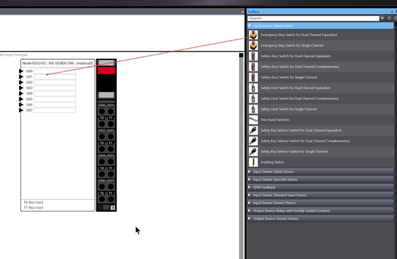
In this article, the emergency stop is wired to Channel 0 and Channel 1, so drop “Emergency Stop Switch for Dual Channel Equivalent” from the Toolbox on the right into Si00. In this article, the emergency stop will be wired to Channel 0 and Channel 1.
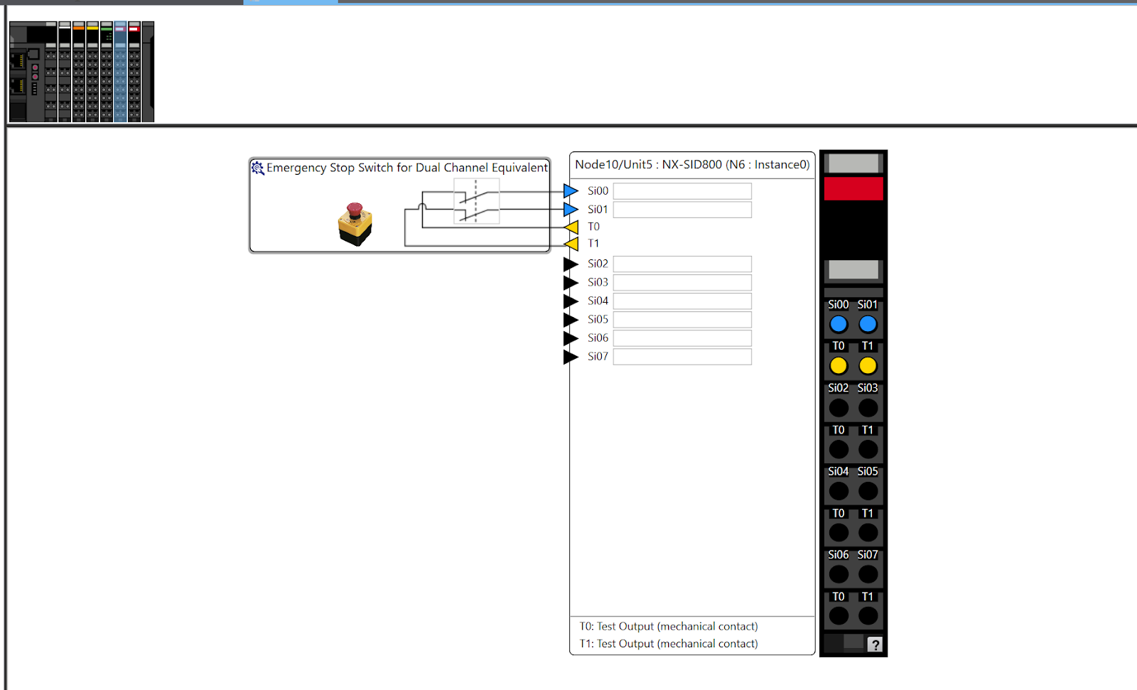
The operation is shown in the diagram below.
Done!
Safety Output
Next, click on the Parameters item in Node10/Unit6 to build the safety output module.

This is the configuration screen for the safety output module.
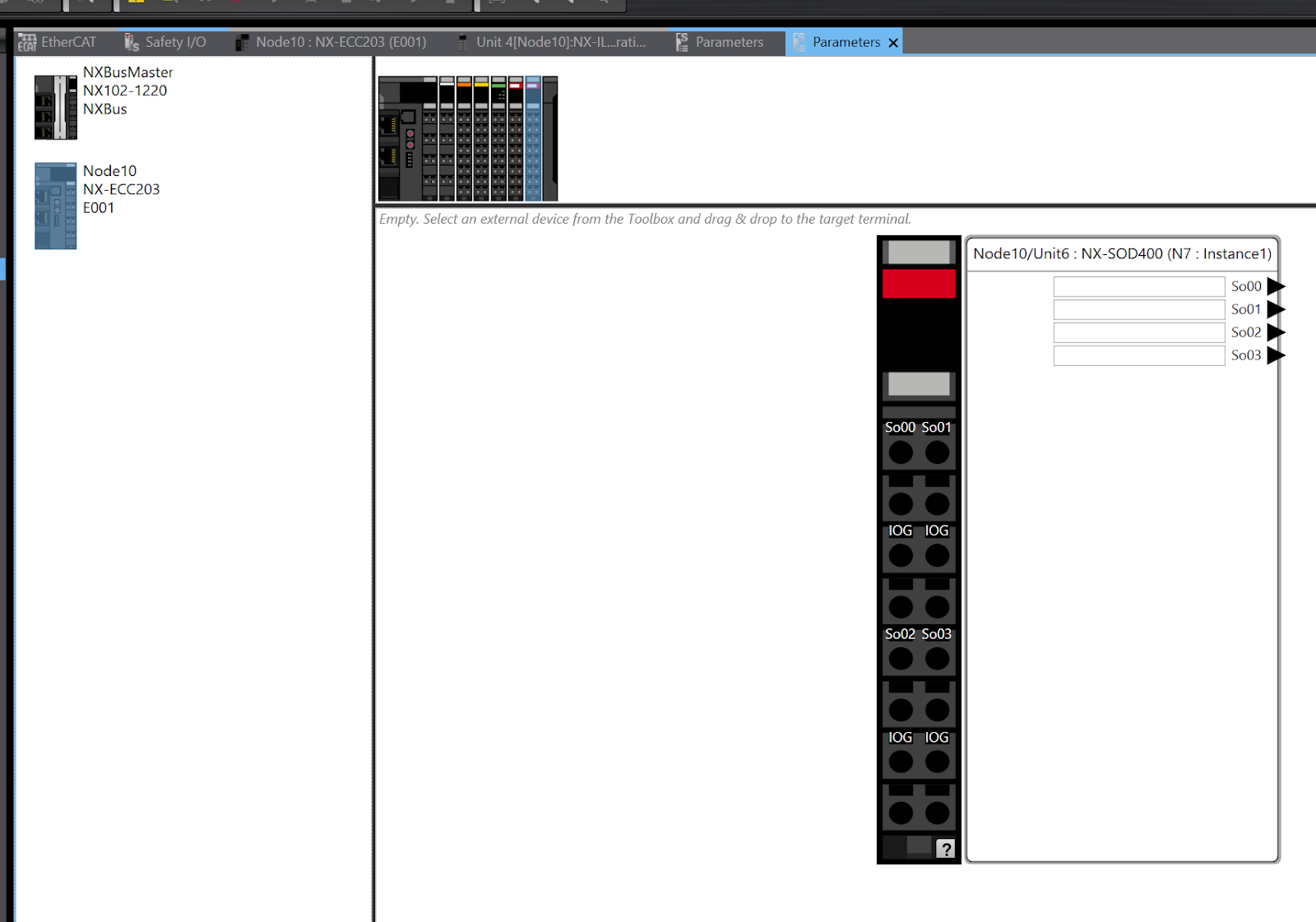
In this article, we just wired the lamp output and wiring to Si00, so Drop Output Device Generic Device>Single Channel with Test Pulse to Si0.
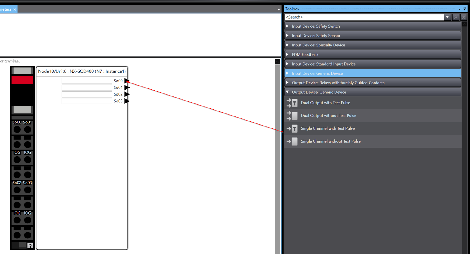
The operation is shown in the diagram below.
Create IO Mapping
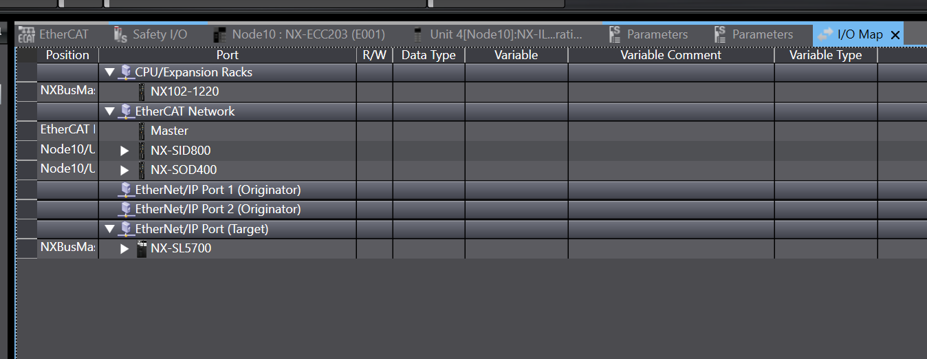
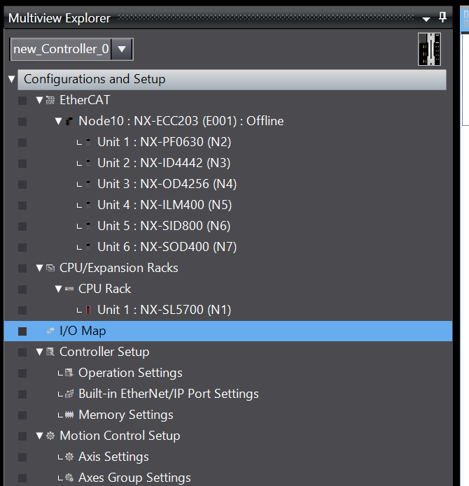
Now open the I/O Map to generate the input/output variables for the safety module.
This is the current project Safety Mapping.
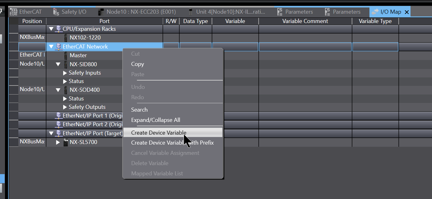
The variables for the EtherCAT Network part have to be generated, right-click on EtherCAT Network>Create Device Variable.
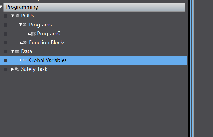
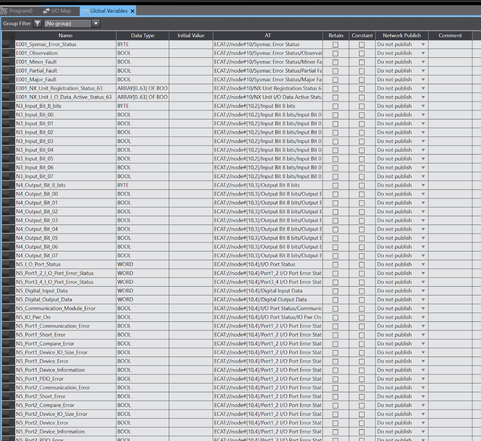
Now that the module-related safety variables have been automatically generated, check the data once in Data>Global Variables,
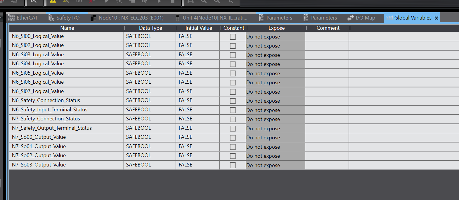
Done!Input and output variables for each safety Slot were also added automatically.
Sysmac Studio generates the variables in an easy-to-understand way according to rules, like the sixth Node (safety input) for N6.
Exposed Variables
The next step is to set up the data exchange between the safe and non-safe programs: if you are experienced with Beckhoff’s TwinSAFE, you cannot access variables in the non-safe program directly from the safe program (and vice versa of course).For this purpose, it is necessary to define the areas in which data are exchanged. In OMRON’s Controller, this function is called “Exposed Variables”.
To define Exposed Variables, open Standard>Slave I/O>Exposed Variables.
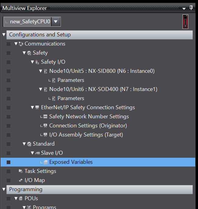
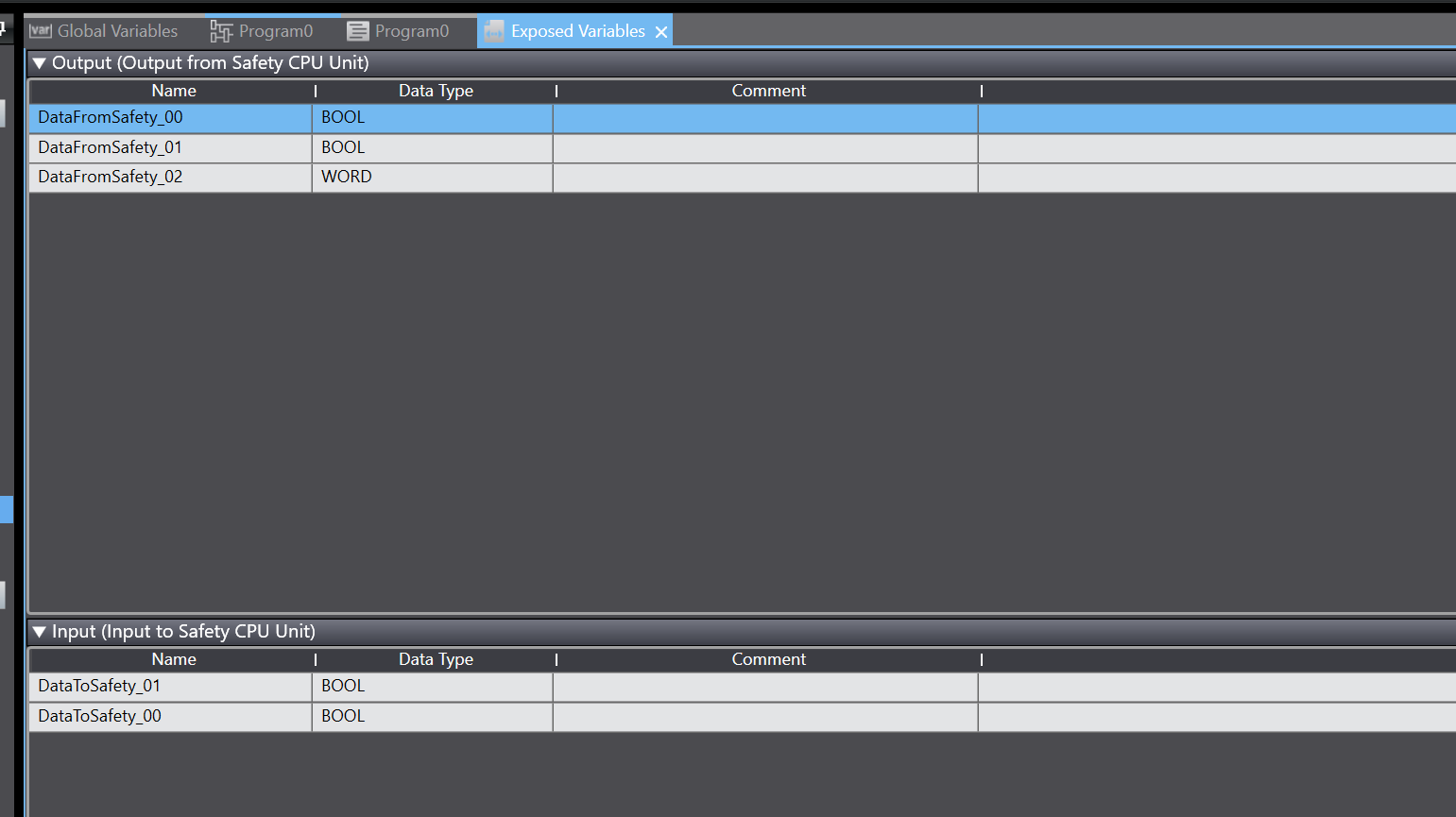
Output becomes the data output by the Safety CPU Unit (SL5700) and Input becomes the input data of the Safety CPU Unit (SL5700).
This time, the output side defines two BOOL variables and one WORD variable, and the input side defines two BOOL variables.
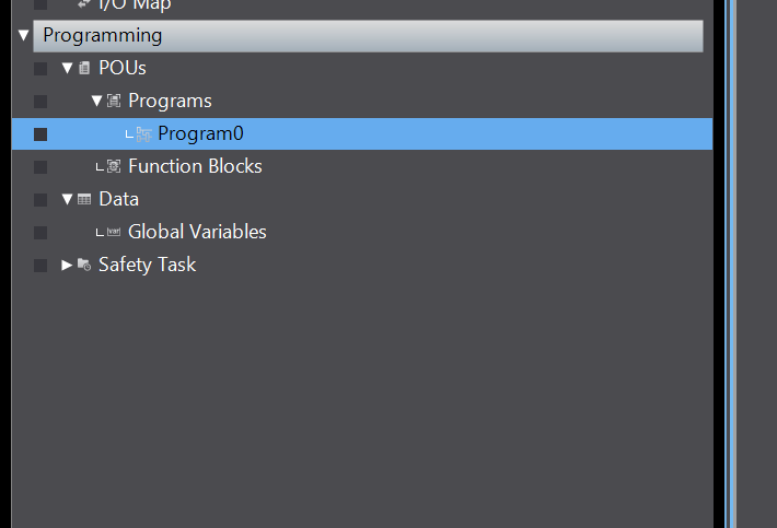
Safety Program
The next step is to create a safety programme at Programming>POUs>Programs>Program0.
Let’s define the following internal variables on the internal side.
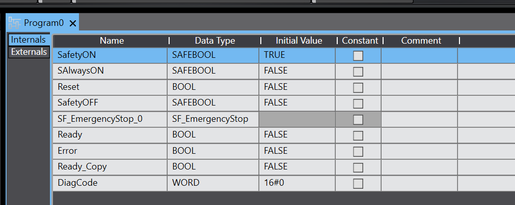
This is the safety program we have created: in Sysmac Studio, safety programs are built in the FBD language.
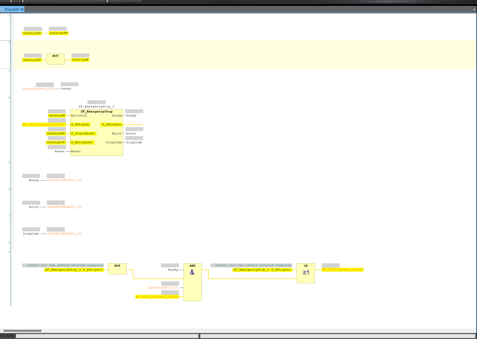
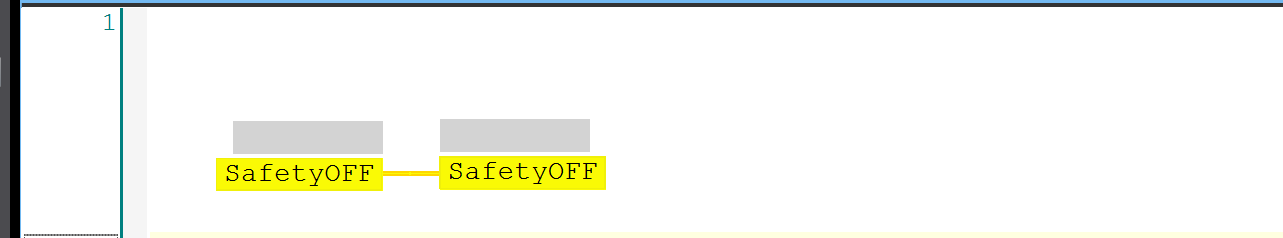
Network1
Network 1 defines the always off signal.
Network2
Network 2 defines the always-on signal.
Network3
Network 3 uses the data received from the Normal PLC as a reset signal within the safety programme.

Network4
Network 4 uses the SF_EmergencyStop Safety Function Block to control the emergency stop. Of course, this can be created from scratch, but OMRON’s Sysmac Studio already provides a large library of Safety Function Blocks.
Network5
Network 5 feeds back the Ready output of SF_EmergencyStop to the Normal PLC.

Network6
Network 6 feeds back the error output of SF_EmergencyStop to the Normal PLC.

Network7
Network 7 feeds back diagnostic information from SF_EmergencyStop to the Normal PLC.

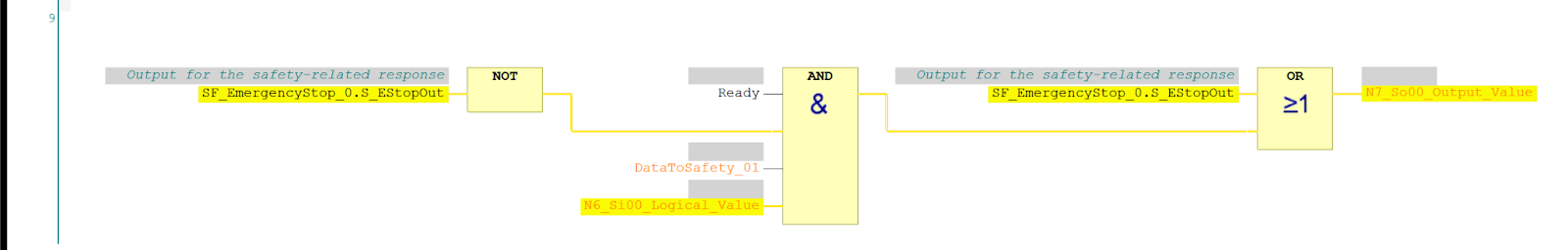
Network9
Network 9 determines whether the lamp output is switched on, flashing or off depending on the status of SF_EmergencyStop.
- Lit: SF_EmergencyStop is in the state that EStopOut is ON, i.e., Ready, and the emergency stop signal is ON and has been reset.
- Flashing: SF_EmergencyStop is in the state that EStopOut is OFF, but SF_EmergencyStop is Ready and the emergency stop signal is ON, that is, waiting for reset.
- OFF; otherwise
Configurare Mapping
After the safety program has been created, the Normal PLC side program is now built.
Open the I/O Map item.
This is the current EtherCAT and Terminal IO definition and confirmation screen. Let’s define variables automatically using the same operation as before.
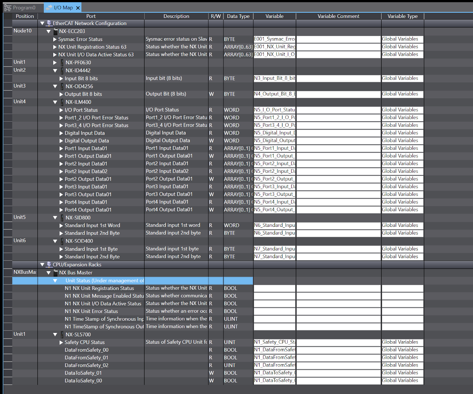
Done!
Program
Data Type
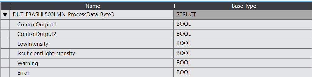
DUT_E3ASHL500LMN_ProcessData_Byte3
This is the structure of OMORN’s IO-LINK distance sensor E3ASHL500LMN Bytes3, which is connected to IML400 this time.
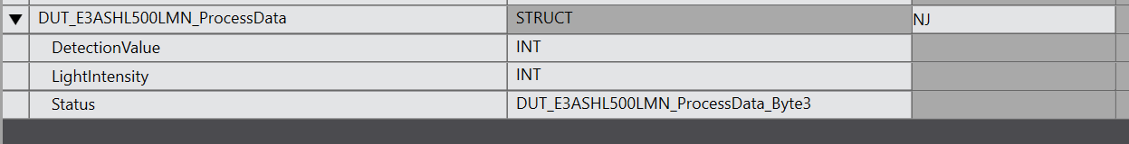
DUT_E3ASHL500LMN_ProcessData
This is a structure that summarizes OMORN’s IO-LINK distance sensor E3ASHL500LMN Bytes0-3, which is connected to IML400 this time.
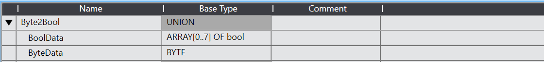
Byte2Bool
This is a community that combines Byte data and Bool array data.
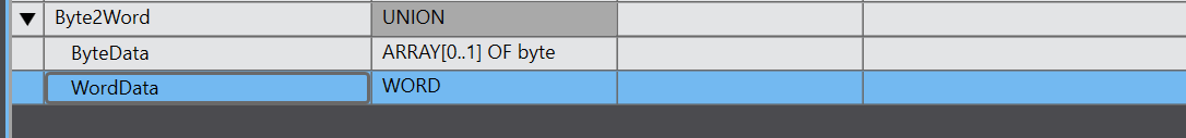
Byte2Word
This is a community of Word data and Byte array data.
Function Block
FB_E3ASHL500MN
This is a Function Block for IO-LINK distance sensor E3ASHL500LMN.
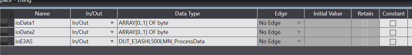
VAR_IN_OUT
These are the input/output variables of the Function Block.
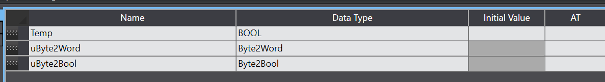
VAR
This is an internal variable of Function Block.
Program
This is the program part of Function Block.
| // Temp:=TRUE; uByte2Word.ByteData[0]:=ioData1[1]; uByte2Word.ByteData[1]:=ioData1[0]; ioE3AS.DetectionValue:=WORD_TO_INT(uByte2Word.WordData); ioE3AS.LightIntensity:=BYTE_TO_INT(ioData2[0]); uByte2Bool.ByteData:=ioData2[1]; ioE3AS.Status.ControlOutput1:=uByte2Bool.BoolData[0]; ioE3AS.Status.ControlOutput2:=uByte2Bool.BoolData[1]; ioE3AS.Status.LowIntensity:=uByte2Bool.BoolData[2]; ioE3AS.Status.IssuficientLightIntensity:=uByte2Bool.BoolData[4]; ioE3AS.Status.Warning:=uByte2Bool.BoolData[6]; ioE3AS.Status.Error:=uByte2Bool.BoolData[7]; |
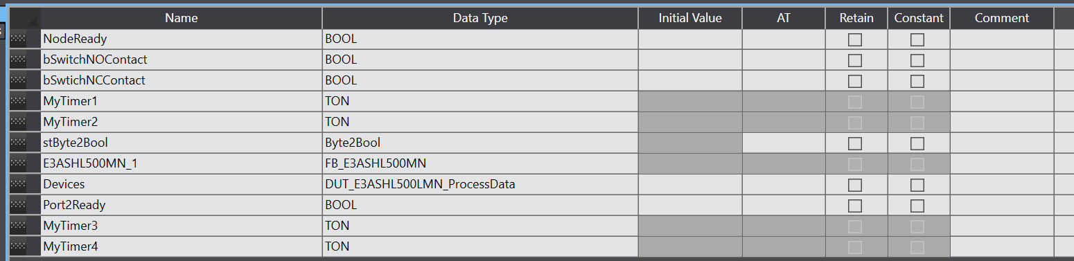
MAIN
This is an internal variable of the MAIN program.
Code
This program accesses each Slave installed in the EtherCAT Coupler and reads and writes data.
| // MyTimer3(In:=not MyTimer4.Q,pt:=T#0.5s); MyTimer4(in:=MyTimer3.Q,PT:=T#0.5s); N1_DataToSafety_01:=MyTimer3.Q; // NodeReady:=_EC_MstrErr=0 and not _EC_CommErrTbl[2]; stByte2Bool.ByteData:=0; stByte2Bool.ByteData:=N3_Input_Bit_8_bits; bSwitchNOContact:=stByte2Bool.BoolData[0]; bSwtichNCContact:=stByte2Bool.BoolData[1]; N1_DataToSafety_00:=stByte2Bool.BoolData[2] AND N1_Program_No_Fault AND N1_Program_Operating AND N6_Si00_Logical_Value ; // stByte2Bool.ByteData:=0; NodeReady:=_EC_MstrErr=0 and not _EC_CommErrTbl[3]; MyTimer1(In:=bSwitchNOContact AND NOT MyTimer2.Q,pt:=T#1s); MyTimer2(in:=MyTimer1.Q,PT:=T#1s); stByte2Bool.BoolData[1]:=bSwtichNCContact OR MyTimer1.Q; N4_Output_Bit_8_bits:=stByte2Bool.ByteData; // Port2Ready:=N5_Port2_IN_Data_Enable AND N5_IO_Pwr_On; NodeReady:=_EC_MstrErr=0 and not _EC_CommErrTbl[4]; E3ASHL500MN_1(ioData1:=N5_Port2_Input_Data01, ioData2:=N5_Port2_Input_Data02, ioE3AS:=Devices); |
Result
You can check EtherCAT and FSoE operation with OMRON NX CPU and SL5700 in this movie.
Download
You can download the project for this article from this link.
https://github.com/soup01Threes/OMRON/blob/main/Project_FSoE_OMRON_NXECC203.smc2