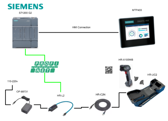
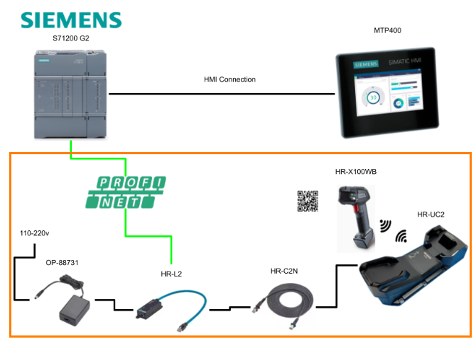
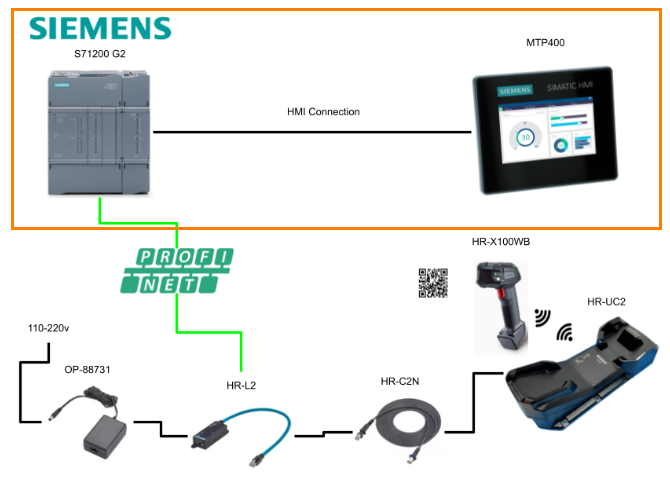
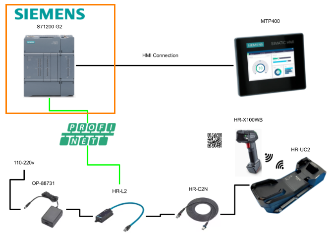
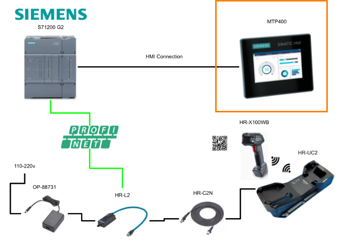
In this article, PROFINET communication is established between SIEMENS S71200 G2 and Keyence HR-X100WB to display data read by QR CODE on the Unified Basic panel MTP400.
Come on, let’s enjoy FA!
Foreword
Thank you from the bottom of my heart for visiting my technical blog and YouTube channel.
We are currently running the “Takahashi Chris” radio show with Full-san (full@桜 八重 (@fulhause) / X) which I deliver every Wednesday night.
Sharing, not hoarding, technical knowledge
We publish technical information related to factory production technology and control systems for free, through blogs and videos.
With the belief that “knowledge should be accessible to everyone,” we share practical know-how and real-world troubleshooting cases from our own field experience.
The reason we keep it all free is simple: to help reduce the number of people who struggle because they simply didn’t know.
If you’ve ever thought:
- “Will this PLC and device combination actually work?”
- “I’m having trouble with EtherCAT communication—can someone test it?”
- “I want to try this remote I/O, but we don’t have the testing environment in-house…”
Feel free to reach out!If lending equipment or sharing your configuration is possible, we’re happy to verify it and share the results through articles and videos.
(We can keep company/product names anonymous if requested.)
How can you support us?
Currently, our activities are nearly all unpaid, but creating articles and videos takes time and a proper testing environment.If you’d like to support us in continuing and expanding this content, your kind help would mean a lot.
Membership (Support our radio show)
This support plan is designed to enhance radio with Mr Full.
https://note.com/fulhause/membership/join
Amazon Gift List (equipment & books for content production)
Lists equipment and books required for content creation.
https://www.amazon.co.jp/hz/wishlist/ls/H7W3RRD7C5QG?ref_=wl_share
Patreon (Support articles & video creation)
Your small monthly support will help to improve the environment for writing and verifying articles.
https://www.patreon.com/user?u=84249391
Paypal
A little help goes a long way.
https://paypal.me/soup01threes?country.x=JP&locale.x=ja_JP
Just trying to share things that could’ve helped someone—if only they’d known.
Your support helps make knowledge sharing more open and sustainable.
Thank you for being with us.
soup01threes*gmail.com
Technical knowledge shouldn’t be kept to ourselves.
Reference Link
PROFINET
PROFINET is an open communication standard defined by PI (PROFIBUS & PROFINET International). Devices compatible with PROFINET can communicate with each other regardless of vendor.

Communication Specifications
Here is the Profinet specification of HR-X100WB used in this article.
- Communication type PROFINET IO
- Communication cycle 8 ms or more
- I/O size 40 to 1400 bytes
- GSDML file version 2.4
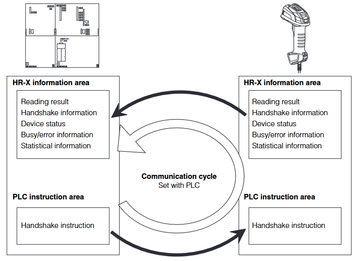
Cyclic Communication
Cyclic communication is a high-speed communication method that periodically sends and receives data at intervals of milliseconds to tens of milliseconds.
Communication settings such as communication cycle and data size are made on the PLC side. If the load is heavy in a network connecting many devices including PROFINET devices, delays and packet losses may occur. Please verify the settings thoroughly before operation.
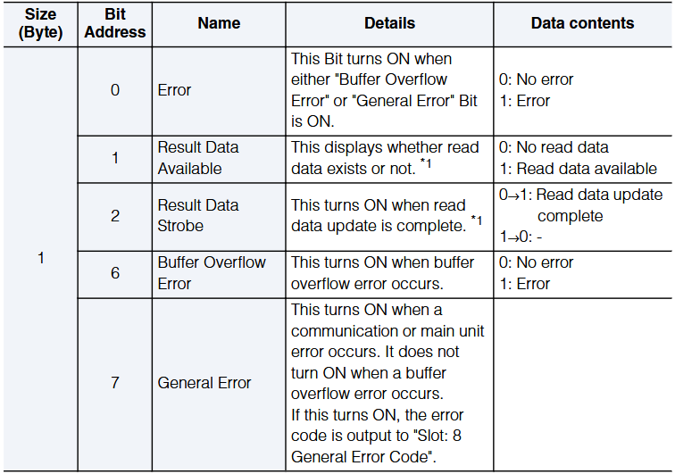
Slot1 Handshake and General Error Status Bits
Here is an overview of HR-X100WB Profinet Slot1.
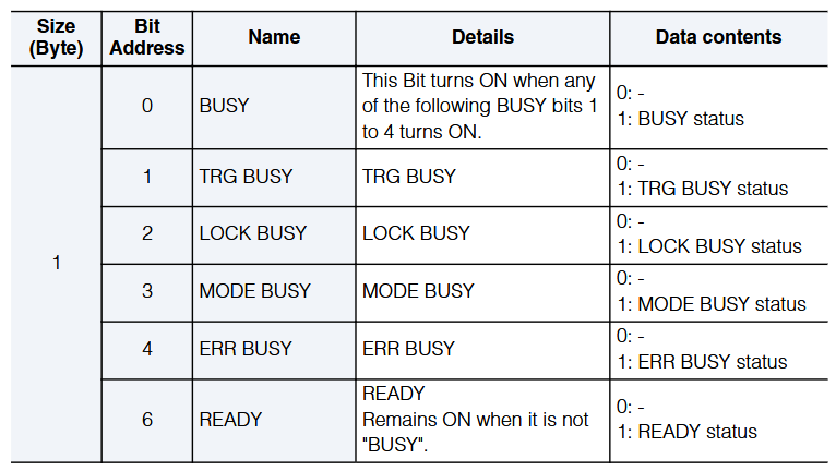
Slot2 BUSY Status Bits
Here is an overview of HR-X100WB Profinet Slot2.
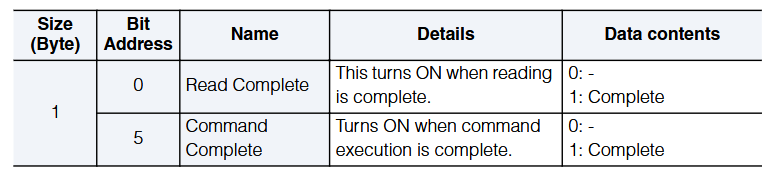
Slot3 Completion Status Bits
Here is an overview of HR-X100WB Profinet Slot3.
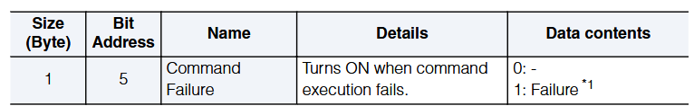
Slot4 Error Status Bits
Here is an overview of HR-X100WB Profinet Slot 4.
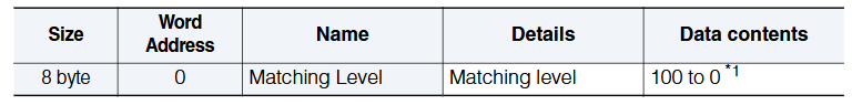
Slot7 Matching Level and General Error Status Bits
Here is an overview of HR-X100WB Profinet Slot7.
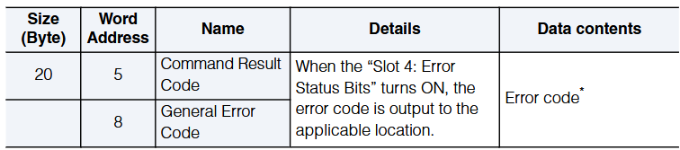
Slot8 Operation Result Status
Here is an overview of HR-X100WB Profinet Slot8.
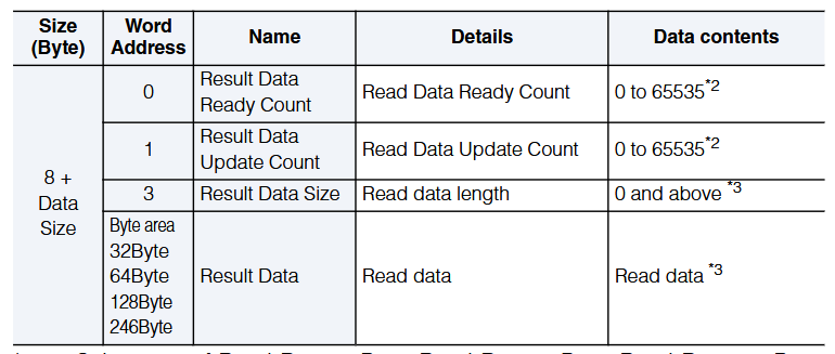
Slot9 Read Data *** Byte
Here is an overview of HR-X100WB Profinet Slot8.
Function
In this article, we will introduce the functions used in the article.
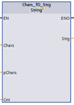
Chars_TO_Strg
The “Chars_TO_Strg” instruction can be used to copy characters from a CHAR or BYTE array to a string of STRING data type, or from a WCHAR or WORD array to a string of WSTRING data type.Note that only ASCII characters are valid for the copy operation.
- Specifies the characters of the (W)CHAR / BYTE / WORD array to be copied into the string with the input parameter CHARS.
- The characters are written to the (W)STRING data type with parameter STRG.
- The number of characters in the string is at least equal to the number of characters copied from the source field.
- If the string is shorter than the number of characters in the source field, characters are written up to the maximum length of the string.
- If the CHAR / BYTE array contains “$00” characters, or if the WCHAR / WORD array contains W#16#0000 characters, the copy operation is performed only up to the corresponding position.
VAR_INPUT
| parameter | data type | Description |
| CHARS | D, L | copy sourceThis is an array of (W)CHAR / BYTE / WORD from which characters are copied. |
| PCHARS | I, Q, M, D, L, P or constant | The position in the (W)CHAR/BYTE/WORD array where the character is copied. |
| CNT | I, Q, M, D, L, P or constant | Number of characters to copy. Use “0” to copy all characters. |
VAR_OUTPUT
| parameter | data type | Description |
| STRG | D, L | Destination of the copy operation.String of (W)STRING data type. Observe the maximum length of the data type:STRING: 254 charactersWSTRING: 254 characters (default) / 16382 characters (maximum) Note that when using WSTRING, any length exceeding 254 characters must be explicitly defined in square brackets (e.g., WSTRING[16382]). |
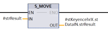
S_MOVE
This instruction can be used to write the contents of the string (W)STRING in parameter IN to the data area specified in parameter OUT.Also, to copy tags of data type ARRAY, use the “MOVE_BLK” and “UMOVE_BLK” instructions.
Implementation
Keyence Side
The first step is to build it from the Keyence side.
Access HR-X100WB Web Server
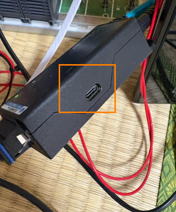
Connect the HR-X100WB main unit to the USB-C type cable.
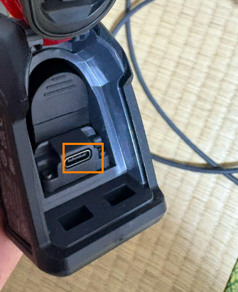
On the PC, the HR-X100WB Drive is found, and inside there is a USB Driver installation FILE.
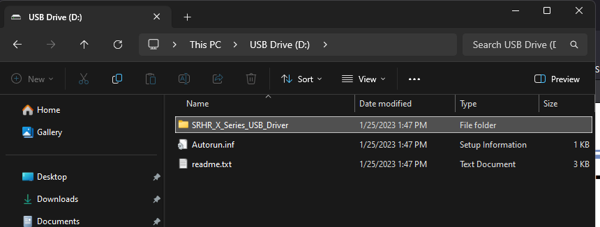
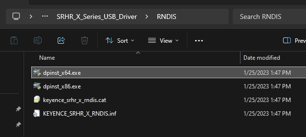
Install the 64Bit or 32Bit USB Driver according to your PC.
The Driver installation screen will appear and proceed with Next>.
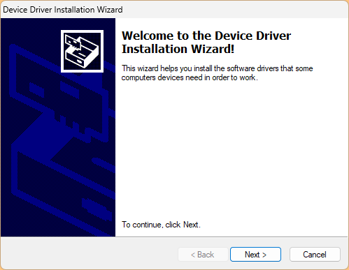
Please wait a moment…
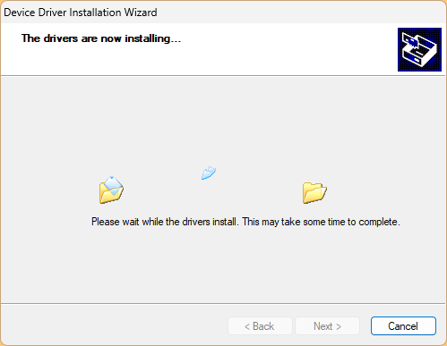
Done!Next, access the following Link.
This is the Web Server for HR-X100WB.
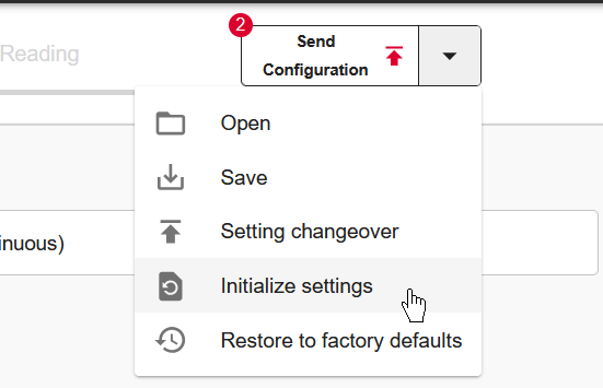
Reset Factory setting
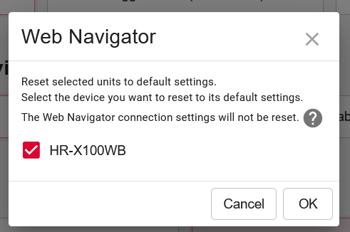
First, to return HR-X100WB to factory settings, click on “Initialize settings” from the Send Configuration drop-list.
OK to proceed.
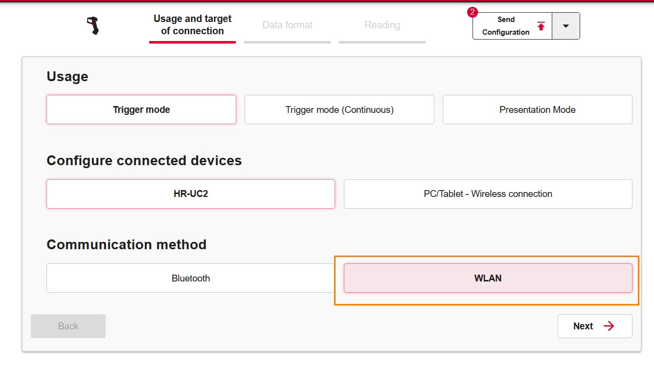
Paring Process
We want to paring HR-UC2 with HR-X100WB, so we set Configure connected devices to HR-UC2.
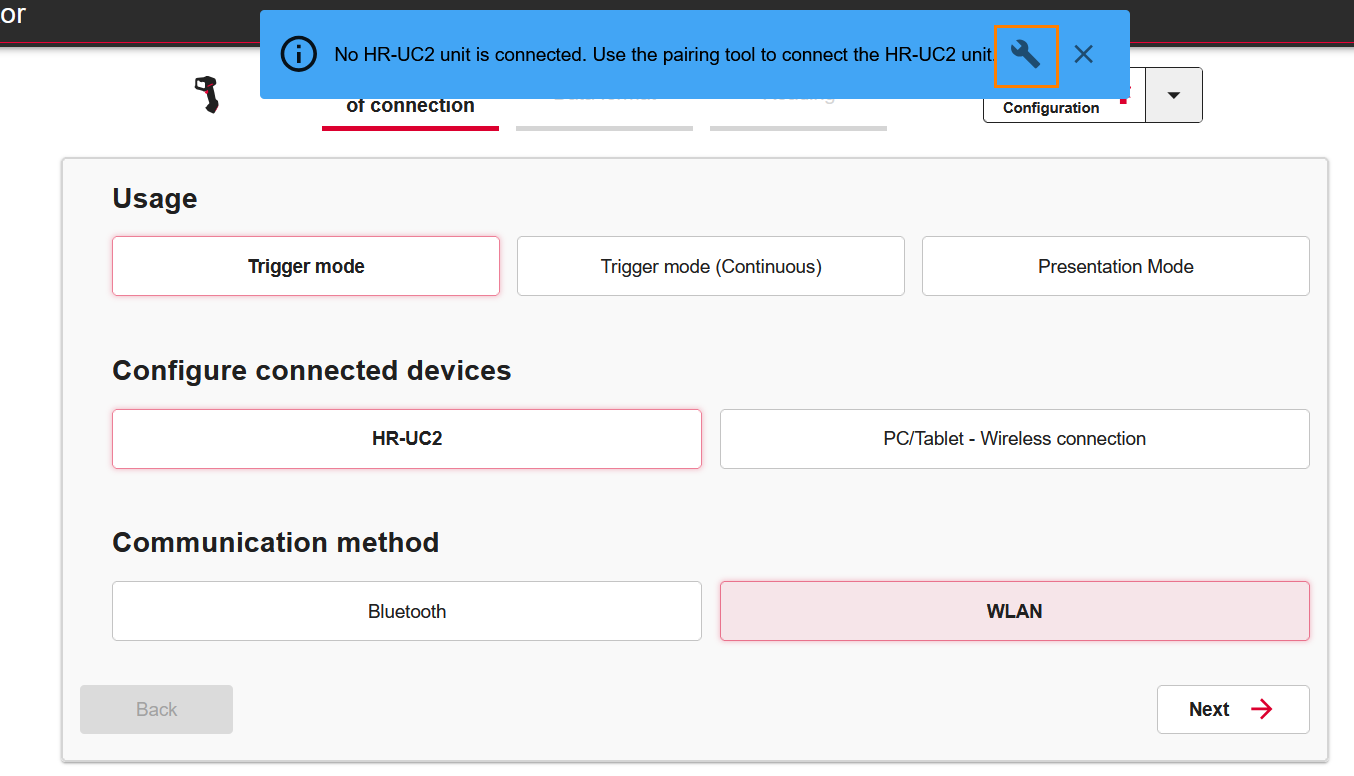
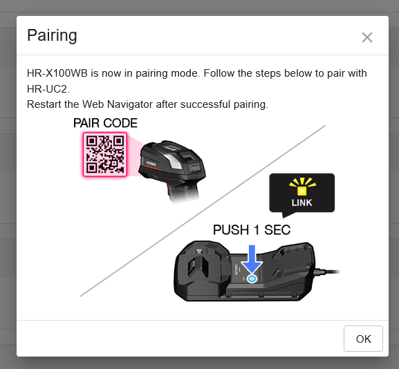
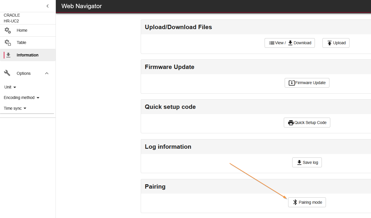
The message “Not Paring with HR-UC2” is displayed from the Web Server, and click ICON in the orange frame below.
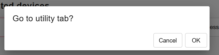
OK to proceed.
Click the Paring Mode button under Paring to change HR-X100WB to Paring mode.
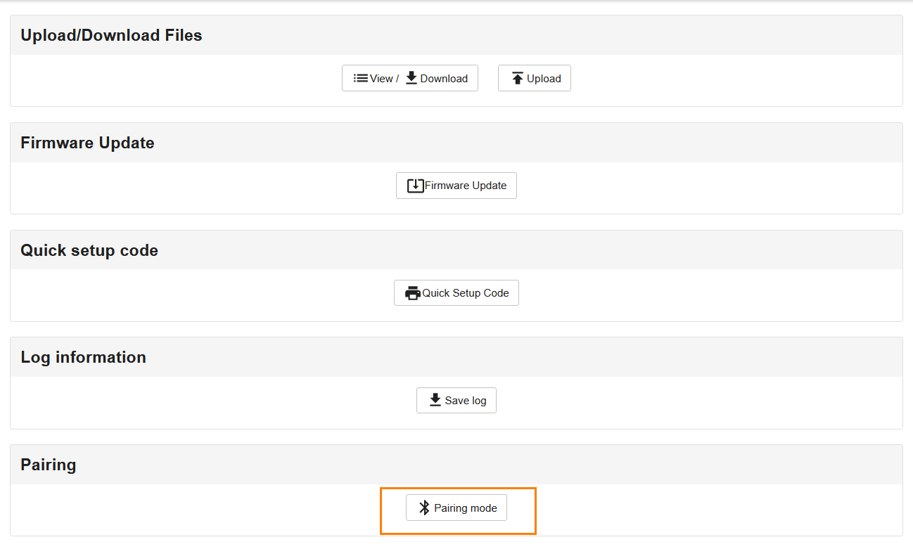
Done!HR-X100WB is now in Pairing Mode.
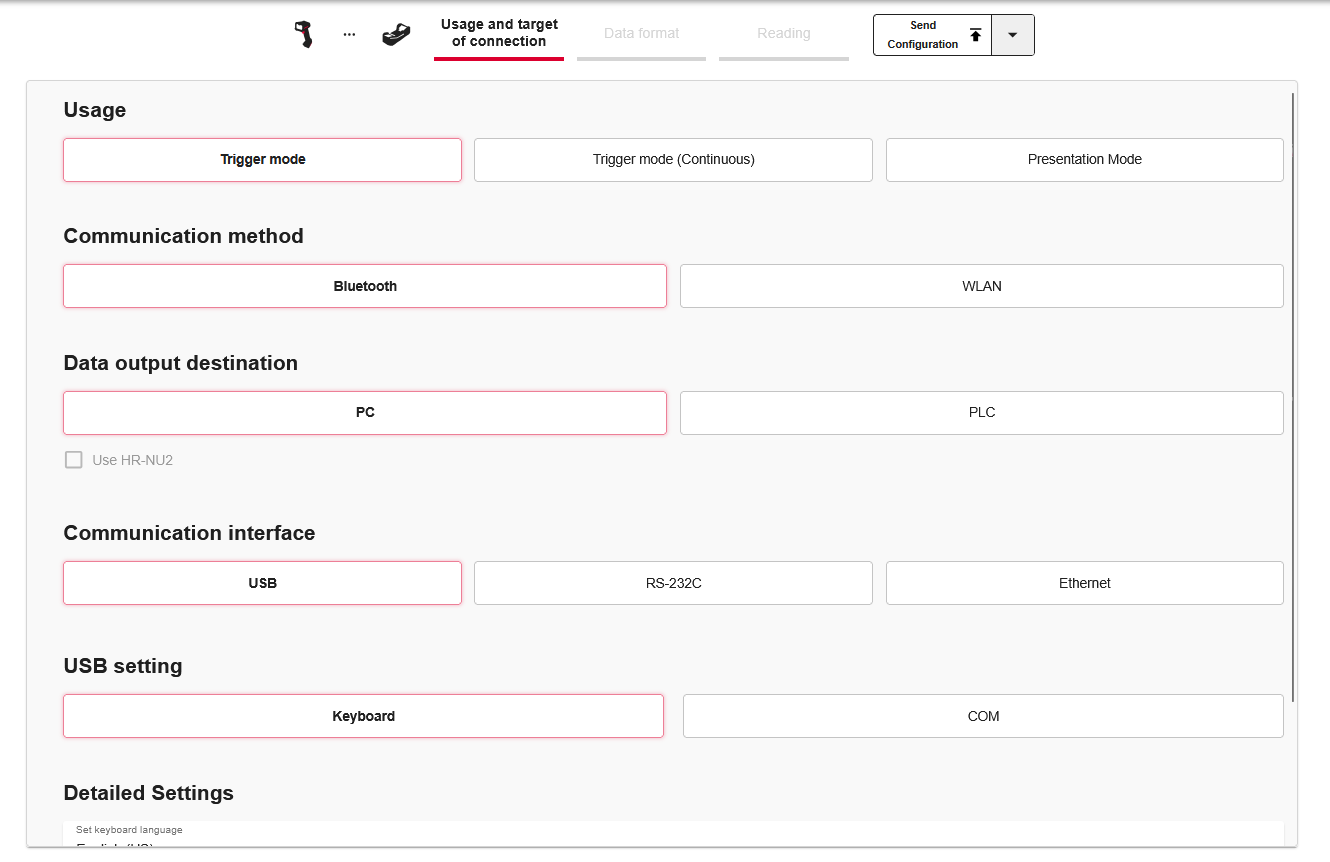
Configure
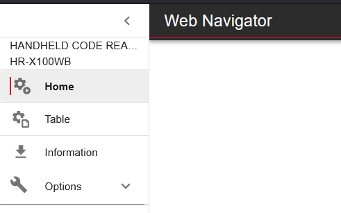
Click the Home button to change the HR-X100WB settings.
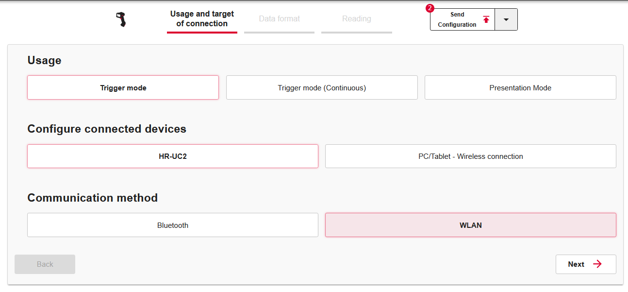
Set communication settings, etc. and proceed with Next.
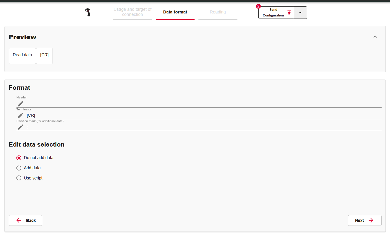
Add Header, etc. to the Data format Tab according to your application.
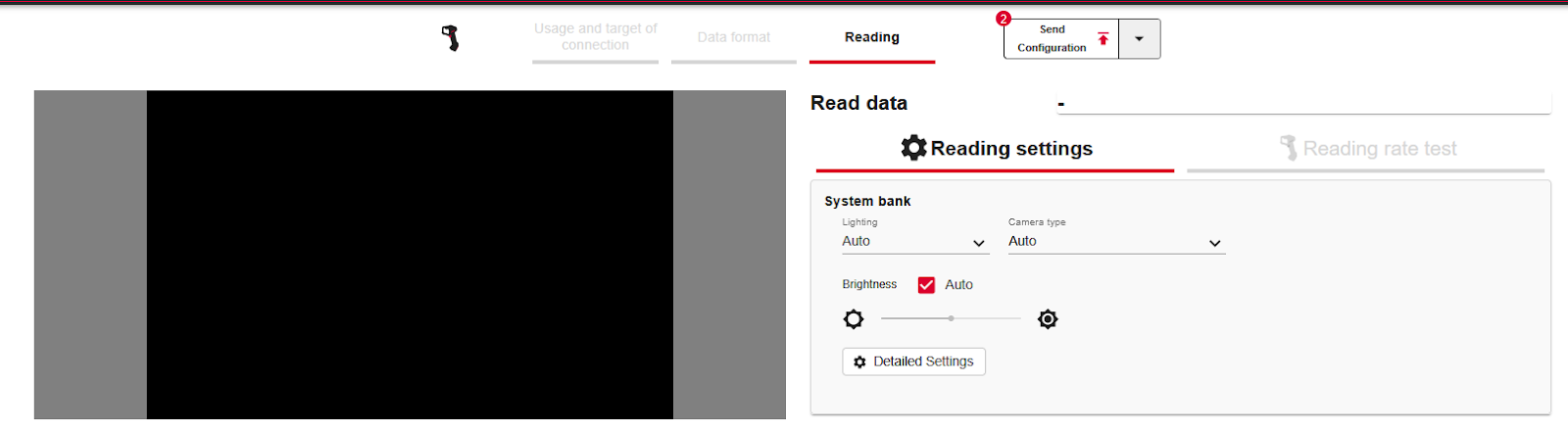
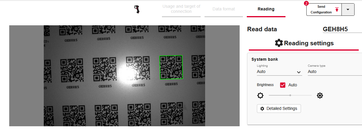
Reading Tab can display photos read by HR-X100WB.
Buzzer Turn OFF
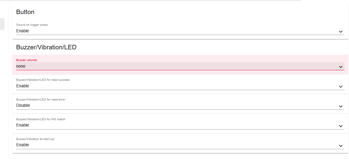
The Buzzer sound of HR-X100WB is quite loud, so we will muffle that Buzzer sound.
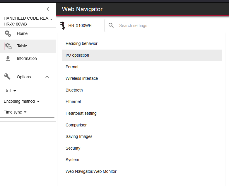
Click Table>I/O Operation.
Set the Buzzer Volume to None on the Buzzer/Vibration/LED.
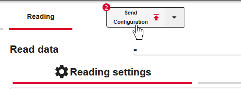
Send Configuration
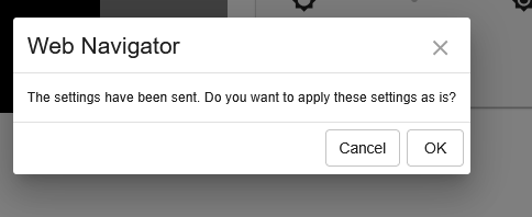
Finally, click Send Configuration to transfer the configuration items to HR-X100WB.
OK to proceed.
Access HR-UC2 Web Server
Now connect the USB-Cke-b to the HR-UC2 and access the following Link.
This is the Web Server screen of HR-UC2.
Pairing Mode
Set HR-UC2 to Pairing Mode so that if both HR-X100WB and HR-UC2 are in Paring Mode, they can pair automatically after 10 seconds.
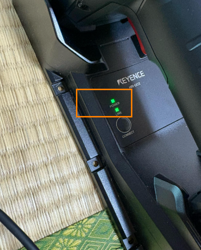
Done!HR-X100WB and HR-UC2 were able to Pairing.
If HR-X100WB and HR-UC2 succeed in Pairing, both POWER and LINK will be lit green.
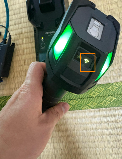
The WIFI ICON on the HR-X100WB main unit will also light up green.
Configuration
The next step is to set up Profinet communication between HR-L2 and the Siemens PLC.
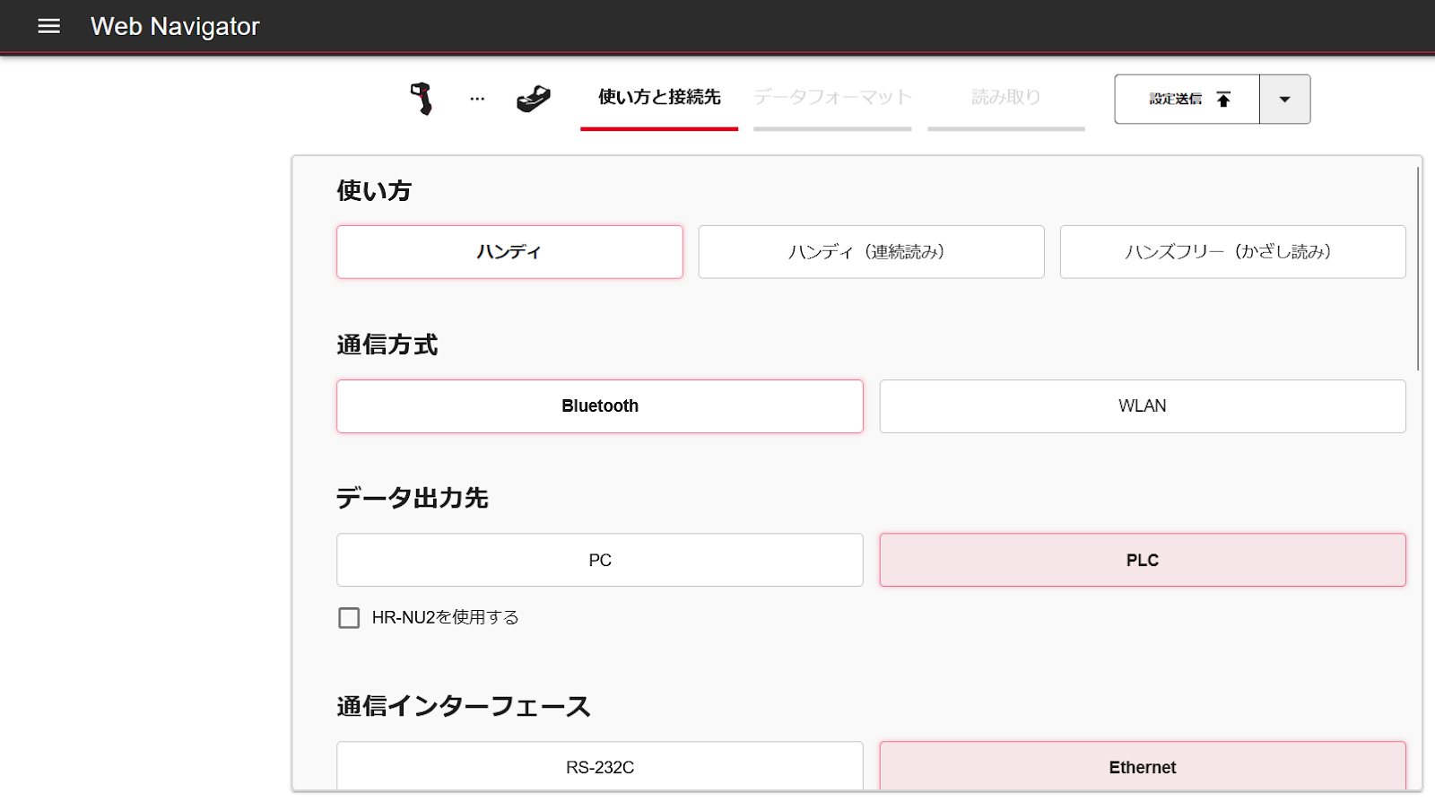
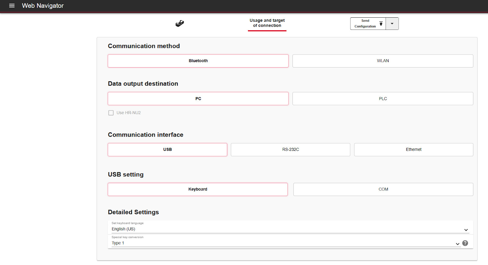
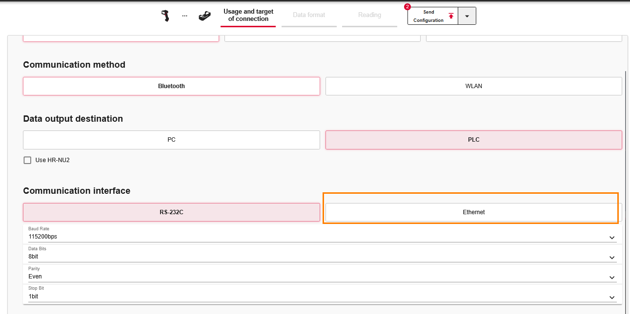
Data out destination
In this case, we will communicate with Siemens S71500 and HR-L2, so we will set Data out destination to PLC.
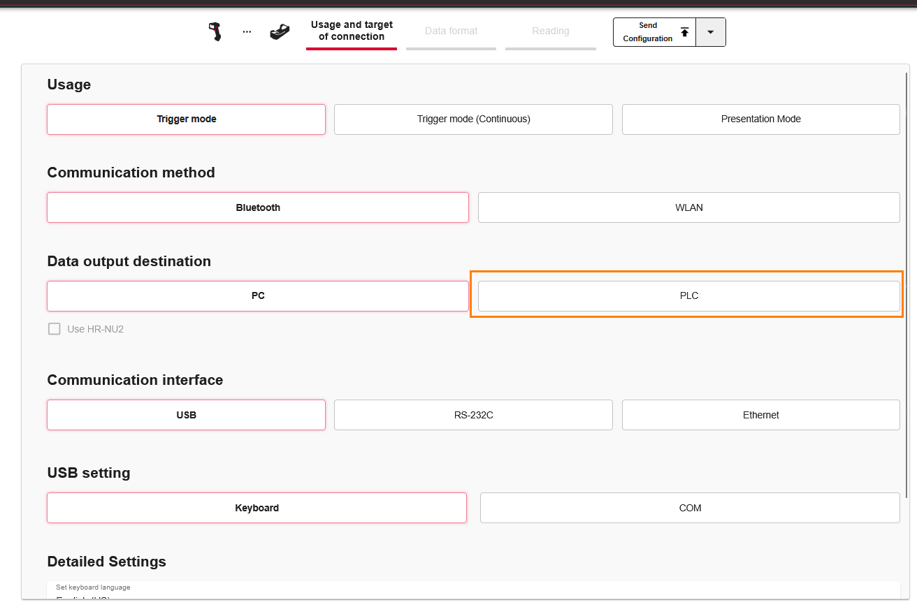
Communication interface
Since Profinet communication with Siemens S71500 is used, set Communication interface to Ethernet.
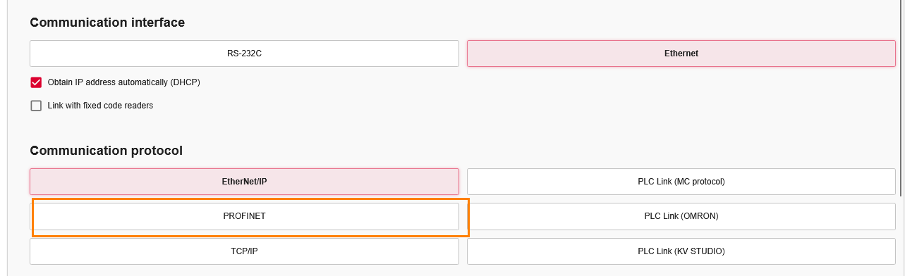
Communication protocol
Set Communication protocol to Profinet.
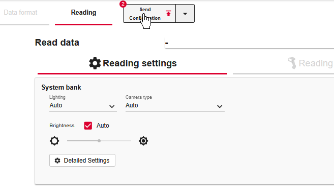
Send Configuration
Finally, click Send Configuration to transfer the parameters.
Siemens Side
The next step is to build the Siemens side.
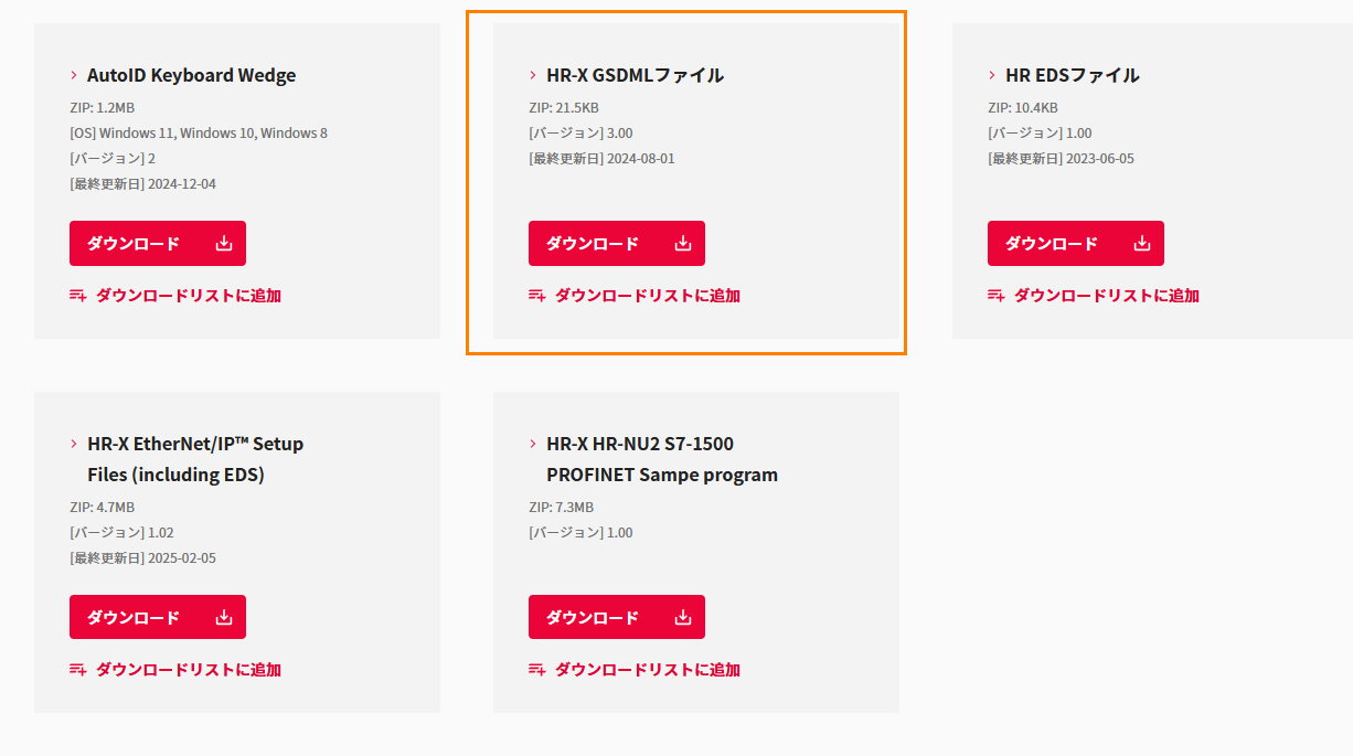
Download GSDML File
Download the Keyence HR-X100WB GSDML File from the link below.
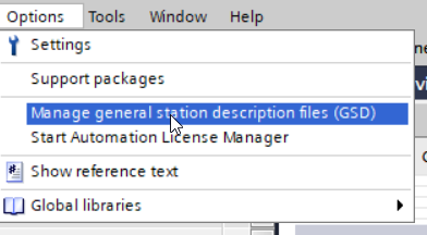
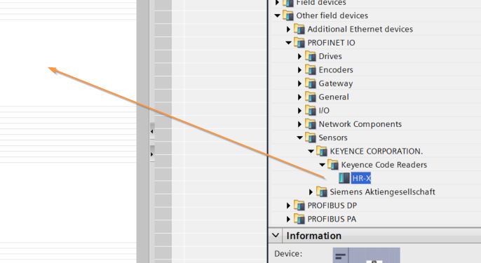
Install GSDML File
Click Options>Manage general station description files (GSD).
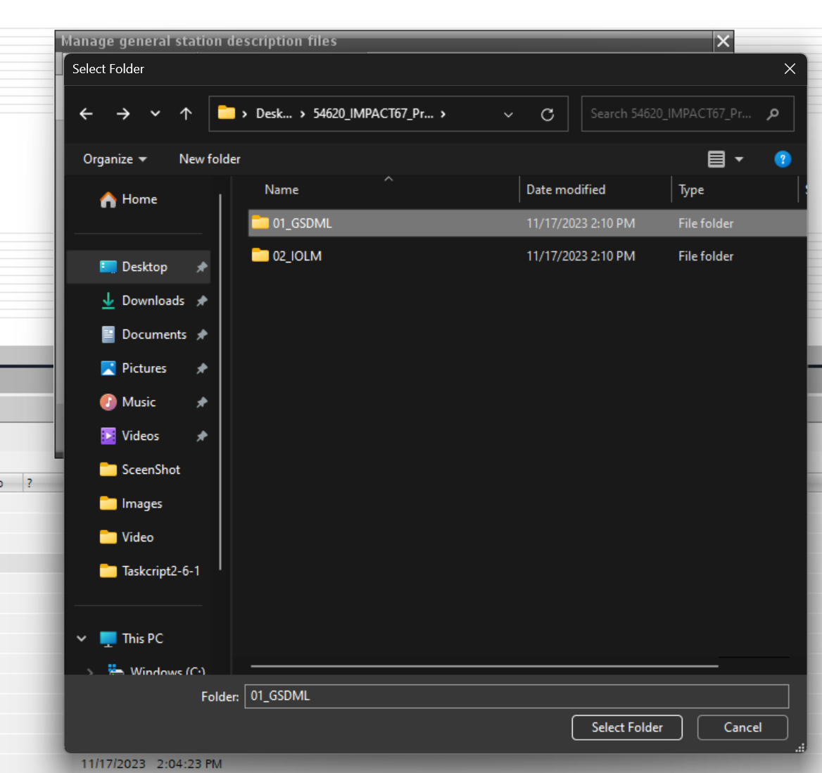
The GSDML administration screen will appear and click on the … button.
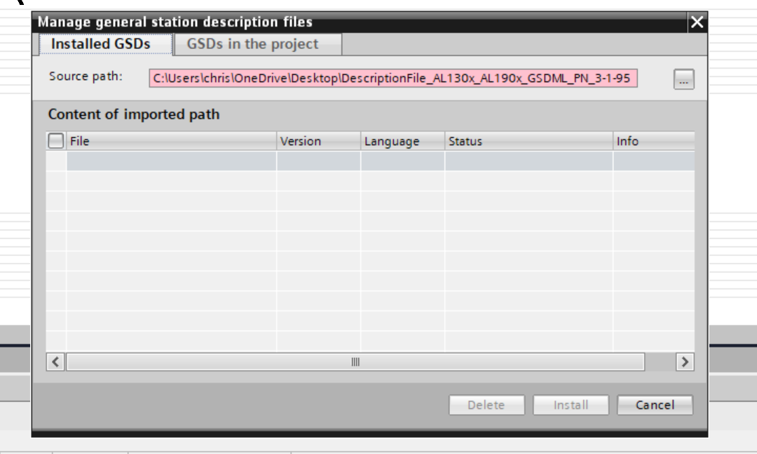
Select the GSDML Folder that was just downloaded.
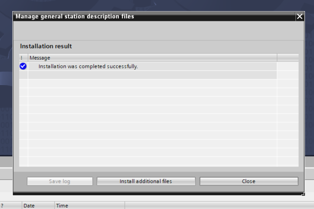
Done!GSDML File is found, install GSDML File with Install.
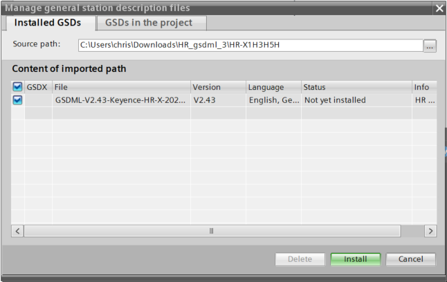
Done!
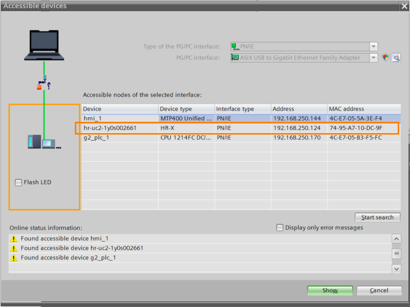
Check Connection
Next, from TIA, CHECK if HR-X100WB is set to PROFINET by clicking the button below.
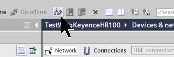
Done!HR-X100WB found.
S7-1200G2 Side
Build the Siemens S7-1200 G2 side.
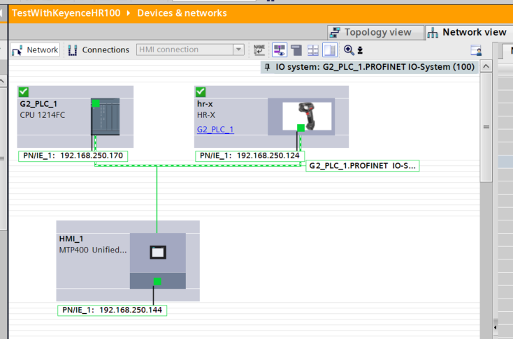
Configuration Profinet Network
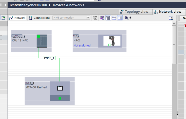
Click on Device & networks to create a Profinet network.
Add the HR-X100WB Profinet device you just added.
Done!
Assign Profinet network
Click Not Assigned to assign HR-X100WB and Siemens S7-1200 G2 to the same Profinet Network.
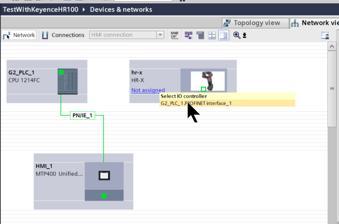
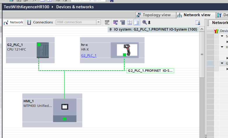
Done!
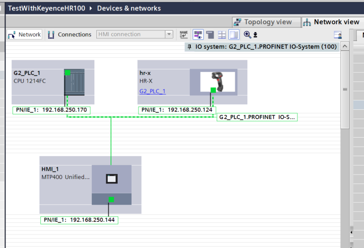
IP Address
Set the IP address of the HR-X100WB to match your application.
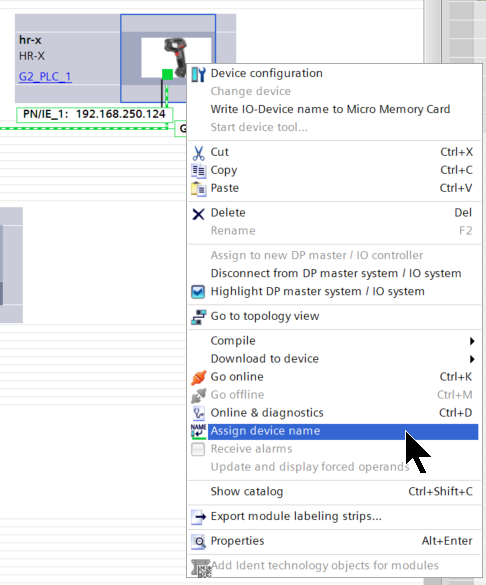
Assign Name
To use Profinet, each Profinet device must also have a Device Name.Right-click the HR-X100WB you just added and select “Assign device name.
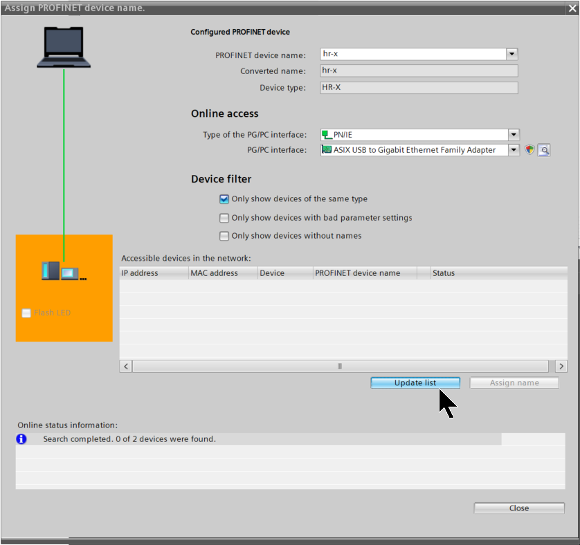
Click Update list.
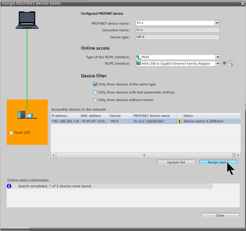
Done!HR-X100WB is found, and a message is also displayed that the Device Name set in the project and the unit are different.Let’s set the device name set in the project in Assign name here.
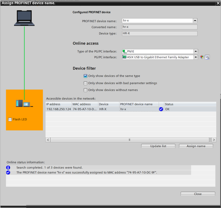
Done!
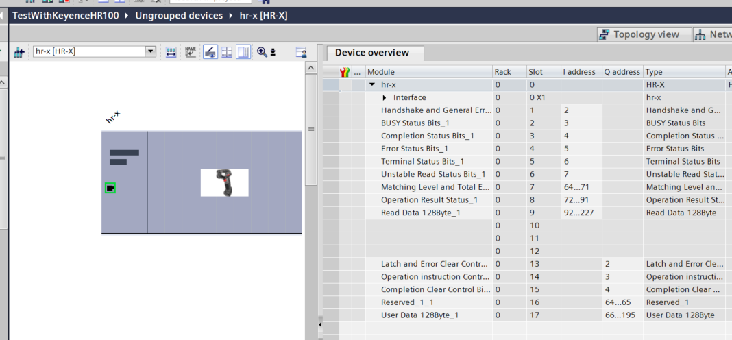
IO Mapping
Now open HR-X100WB and set the IO address for each Slot.
User Data Type
プログラムに使用する構造体を定義します。
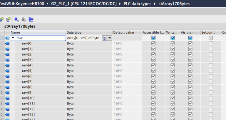
stArray170Bytes
This one defines a 170-byte array structure.
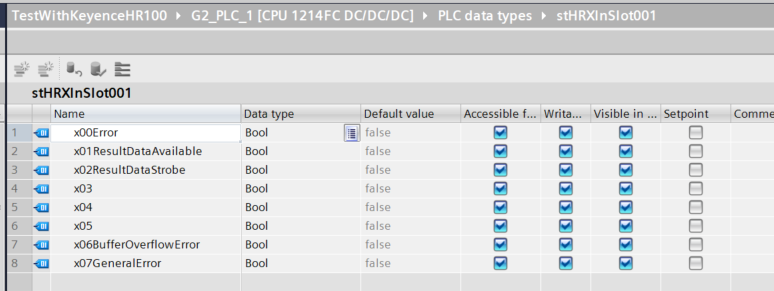
stHRXInSlot001
This one defines the data for Profinet communication Slot1 of Keyence HR-X100WB.
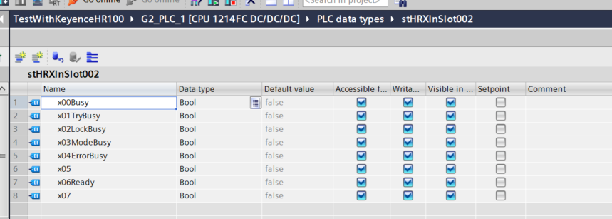
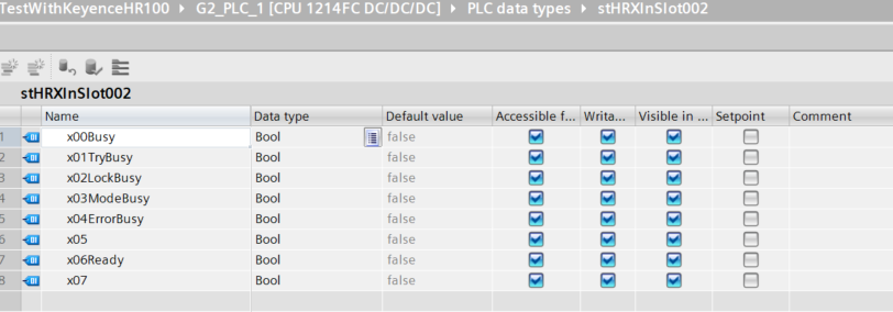
stHRXInSlot002
This one defines the data for Profinet communication Slot2 of Keyence HR-X100WB.
stHRXInSlot003
This one defines the data for Profinet communication Slot3 of Keyence HR-X100WB.
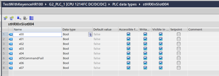
stHRXInSlot004
This one defines the data for Profinet communication Slot4 of Keyence HR-X100WB.
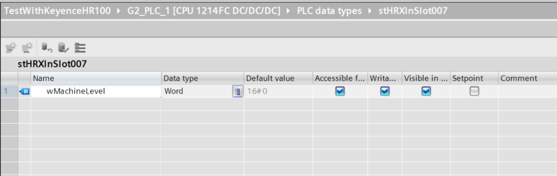
stHRXInSlot007
This one defines the data of Profinet communication Slot7 of Keyence HR-X100WB.
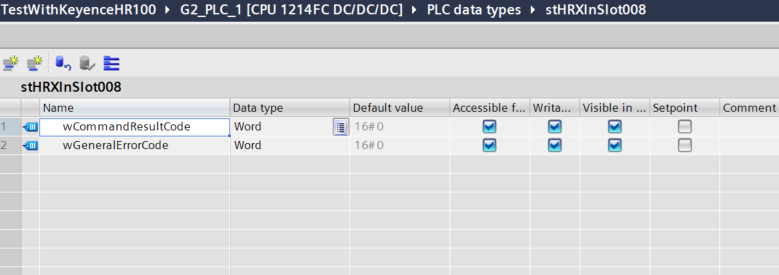
stHRXInSlot008
This one defines the data for Profinet communication Slot8 of Keyence HR-X100WB.
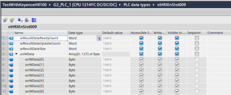
stHRXInSlot009
This one defines the data for Profinet communication Slot 9 of Keyence HR-X100WB.
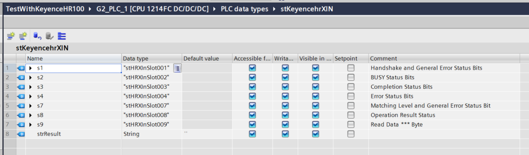
stKeyencehrXIN
This is a structure that summarizes the Slot defined earlier and even defines a variable to store the read data in a string.
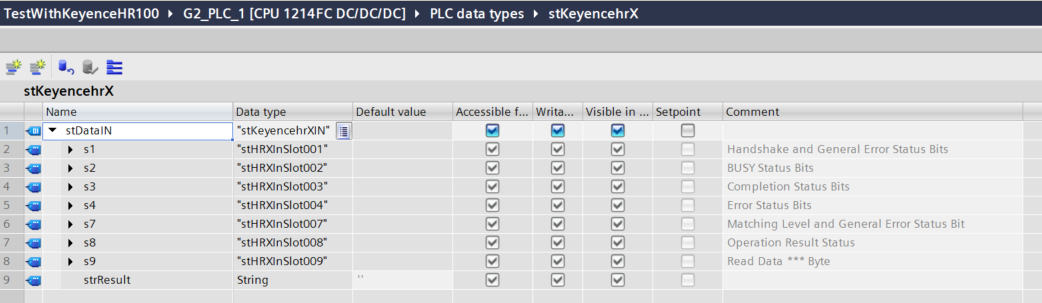
stKeyencehrX
This is a structure that summarizes all the input data for HR-X100WB.
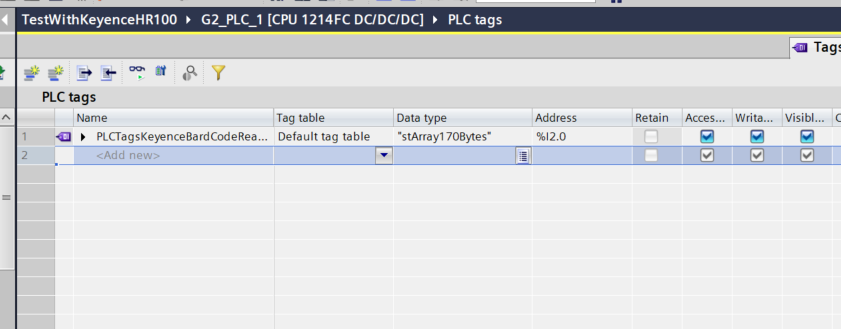
PLC Tags
Define the TAG according to the IO address you defined for HR-X100WB in IO Mapping earlier.
Function
The next step is to define the FUNCTION to be used for the project.
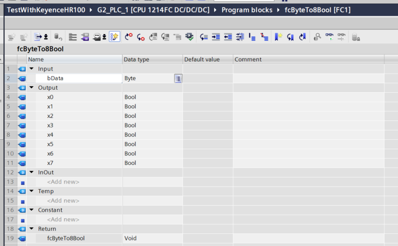
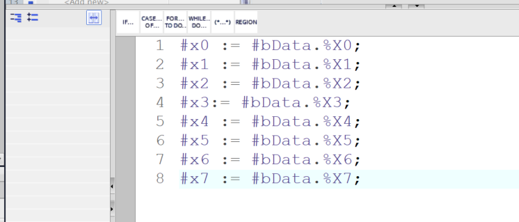
fcByteTo8Bool
This FC implements the function to decompose a Byte into 8 Bools.
Function Block
The next step is to define a dedicated FB for HR-X100WB.
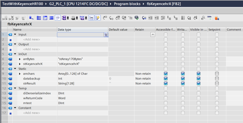
fbKeyencehrX
This is the Interface of FB.
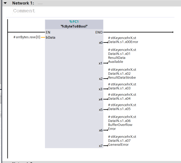
Network1
Network1 uses the fcByteTo8Bool defined earlier to break Slot1 data into structures.
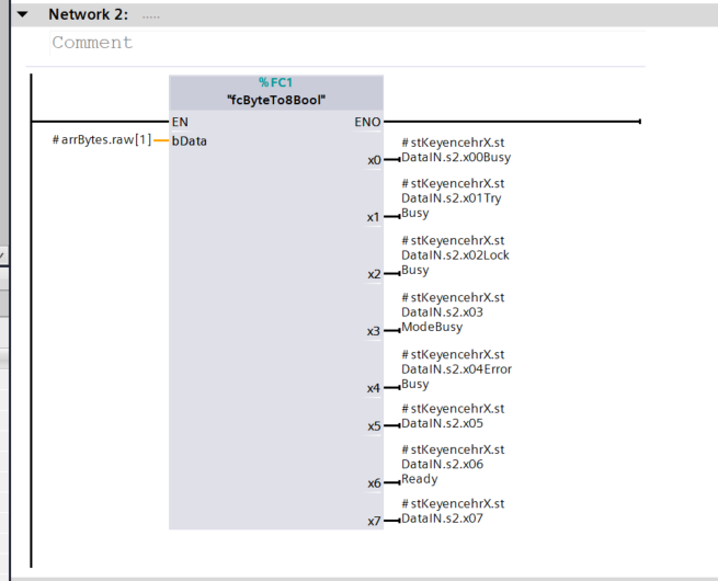
Network2
Network2 uses the fcByteTo8Bool defined earlier to break Slot2 data into structures.
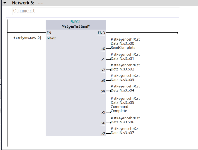
Network3
Network3 uses the fcByteTo8Bool defined earlier to break Slot3 data into structures.
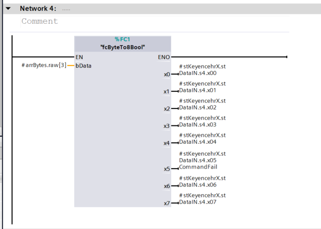
Network4
Network4 uses the fcByteTo8Bool defined earlier to break Slot4 data into structures.
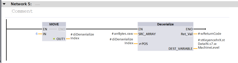
Network5
Network5 uses the Deserialize function to select the Index of the array and obtain the Machine Level value of Slot7.
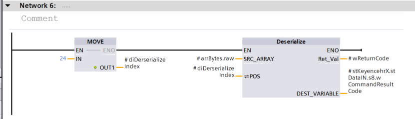
Network6
Network6 uses the Deserialize function to select the Index of the array and obtain the Command Result code value for Slot8.
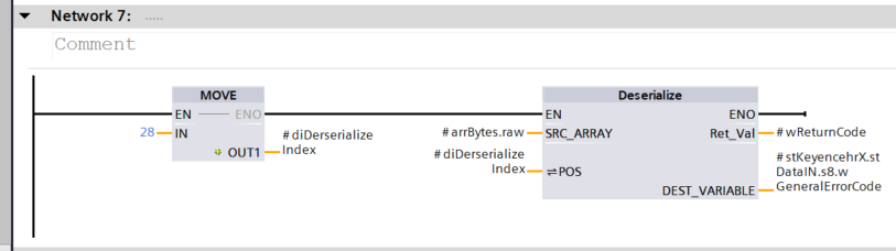
Network7
Network7 uses the Deserialize function to select the Index of the array and obtain the error code value for Slot8.
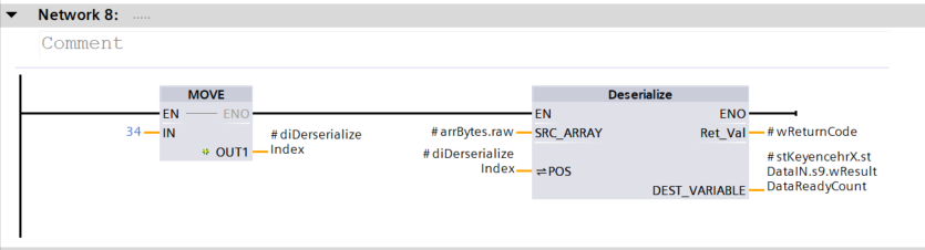
Network8
Network8 uses the Deserialize function to select the Index of the array and obtain the Result Data Ready Count value for Slot9.
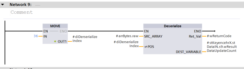
Network9
Network9 uses the Deserialize function to select the Index of the array and obtain the Result Data Update Count value for Slot9.
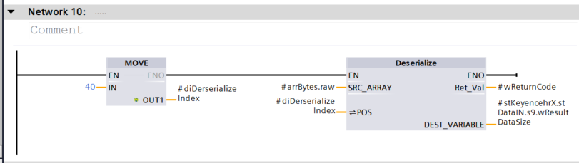
Network10
Network10 uses the Deserialize function to select the Index of the array and obtain the Result Data Size value for Slot9.
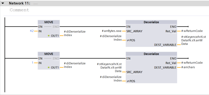
Network11
Network11 uses the Deserialize function to select the Index of the array, retrieve the Result Data value in Slot9, and transfer it again to the character array.
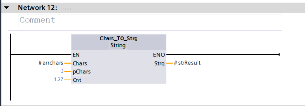
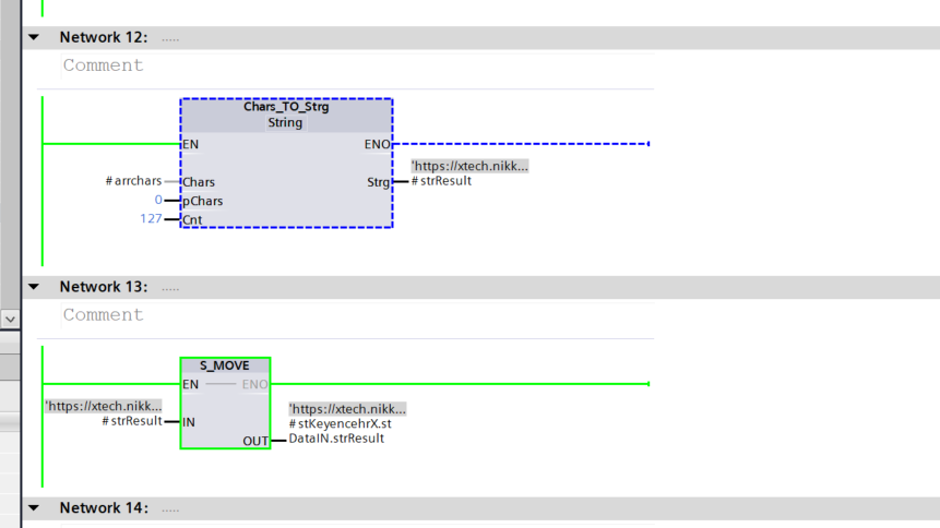
Network12
Network12 uses the Chars_TO_Strg function to transfer the current value of the CHAR array to the STRING variable.
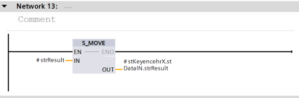
Network13
Network13 uses S_MOVE to transfer strings to variables in the structure.
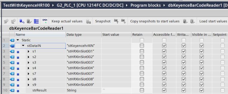
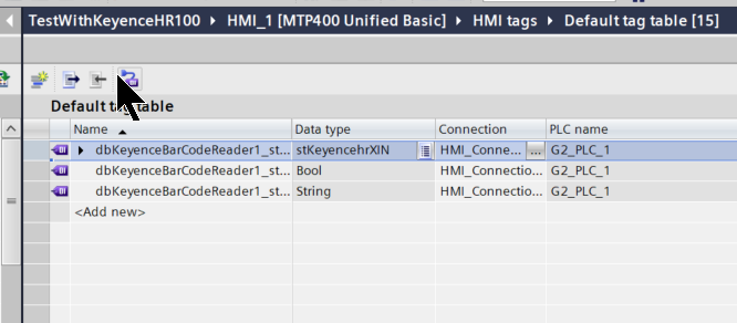
dbKeyenceBarCodeReader1
Define DB and specify the stKeyenceXIN defined earlier.
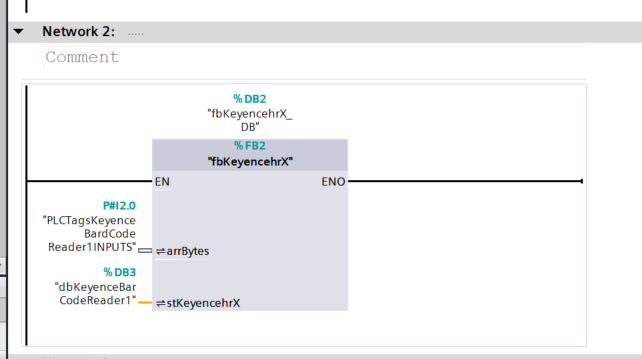
OB1
OB1 calls the FB defined earlier.
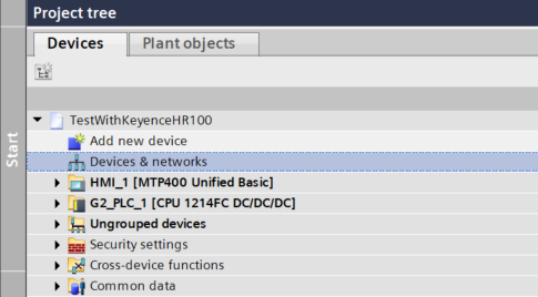
HMI Side
Now we will build the MTP400 Unified Basic panel side.
Connect PLC to HMI
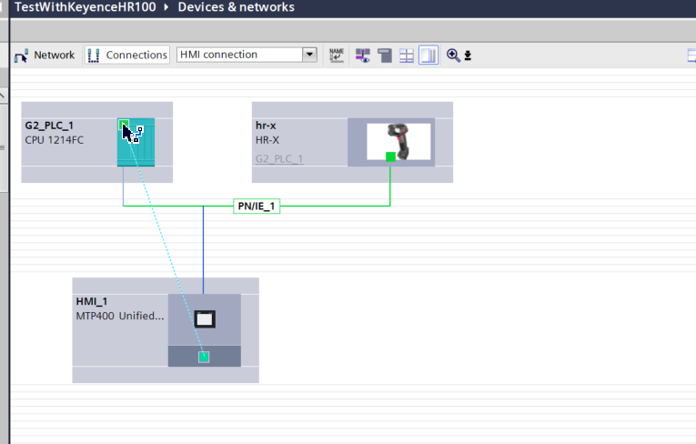
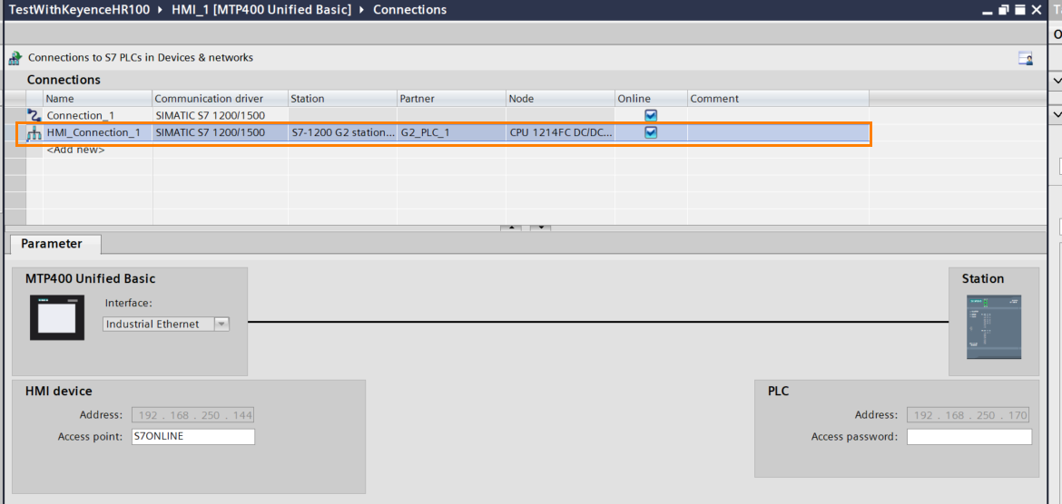
To create an HMI connection between the S71200 G2 and the MTP400 Unified Basic panel, click the Connections button under Devices & networks.
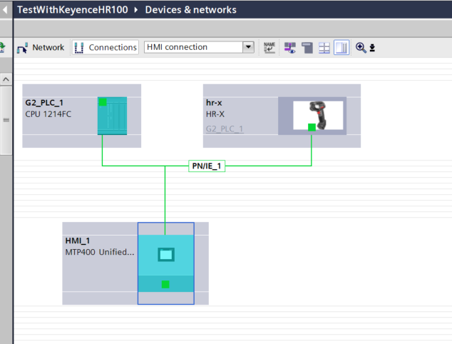
HMI and S71200 G2 are connected via Drop.
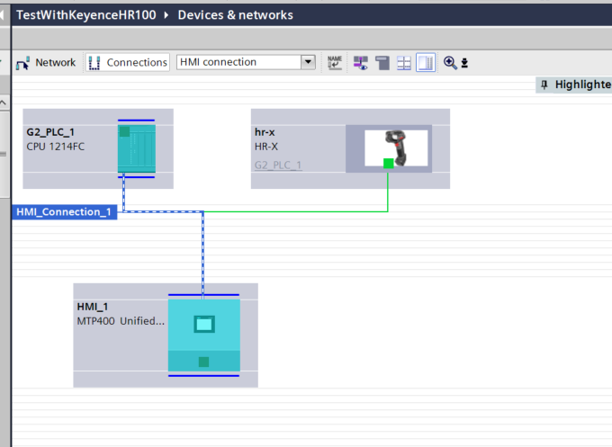
Done!So we have an HMI connection between the S71200 G2 and the MTP400.
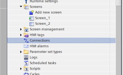
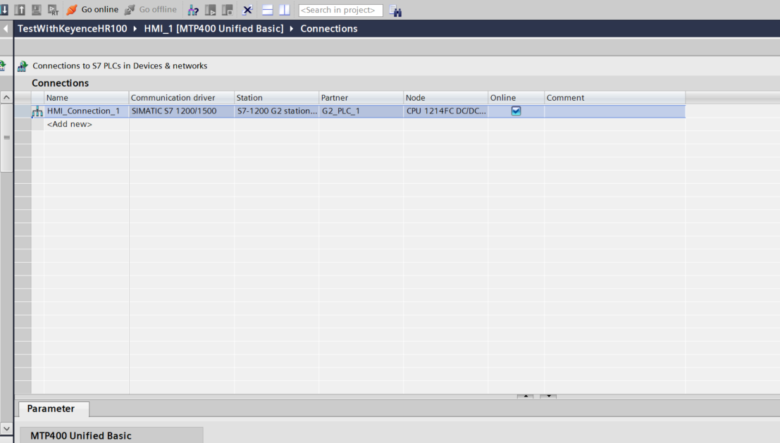
Opening the Connections Tab also confirmed the HMI_Connection defined earlier.
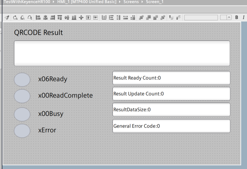
Screen
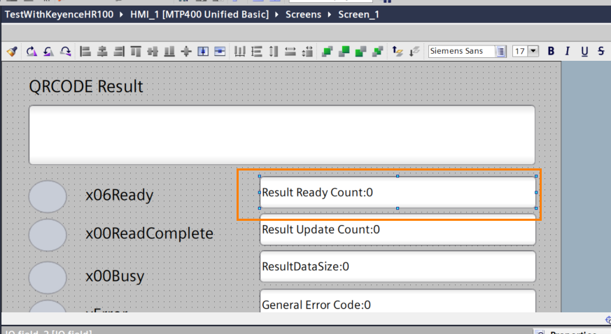
This is the screen we created for this article, which visualizes the result of reading the QR Code and the status of HR-X100WB.
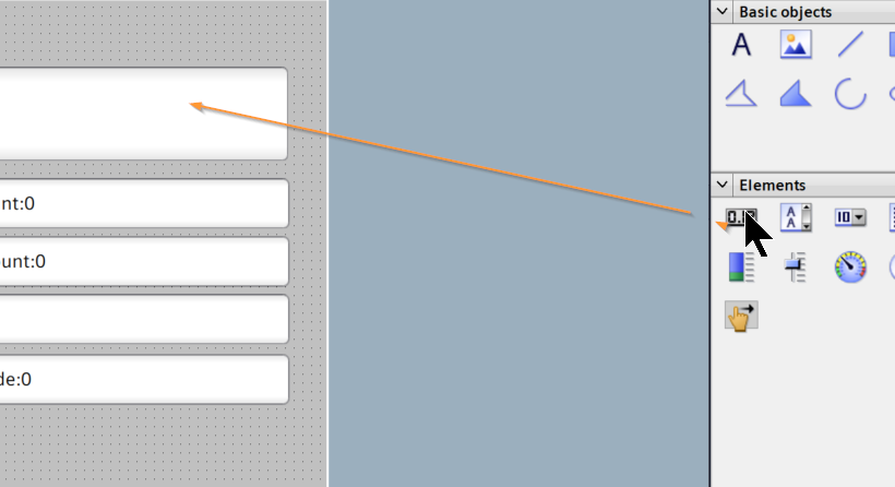
Add I/O Field
Add an I/O Field from Elements to display QR Code results.
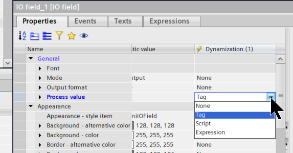
Open Properties of the I/O Field and select Tag for General>Process value>Dynamization(1).This will make the text displayed in the I/O Field the Tag connected to the PLC, etc.
Click on the Tag screen>Process>… button on the right.
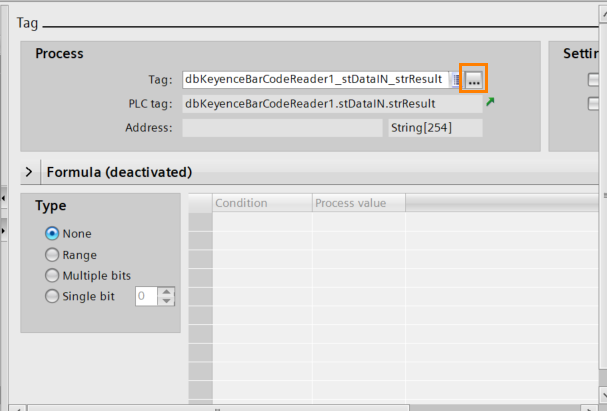
Select the PLC tag to be connected to the corresponding I/O Field.
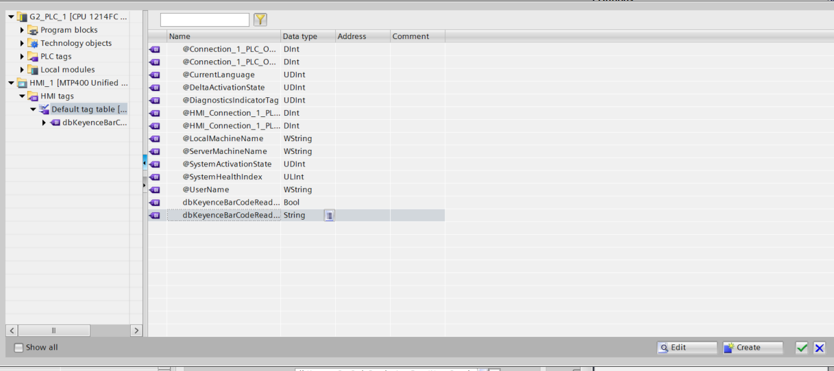
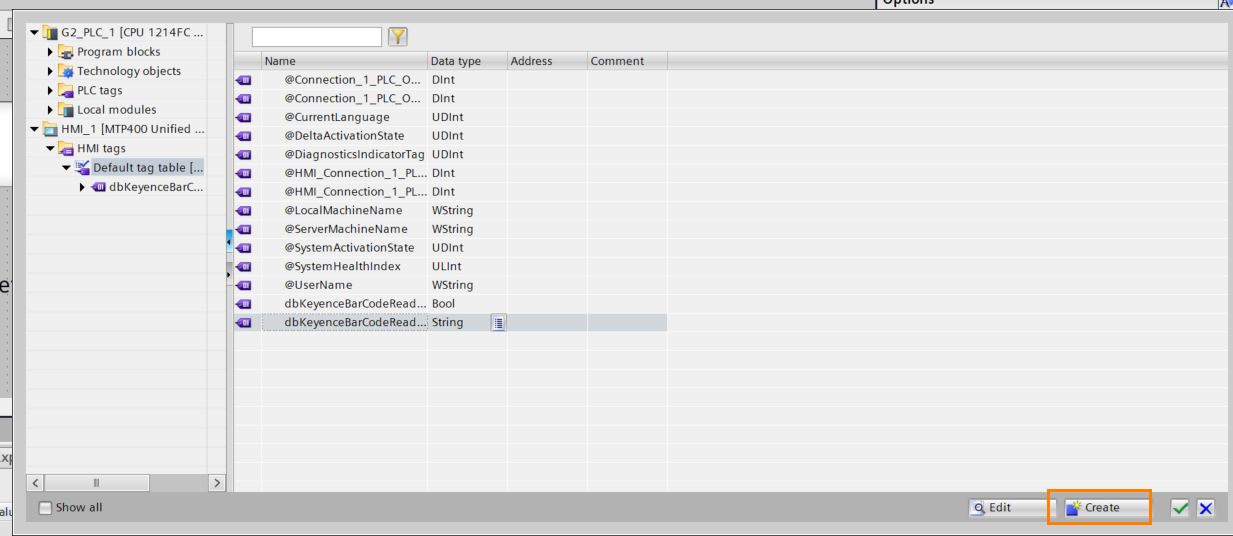
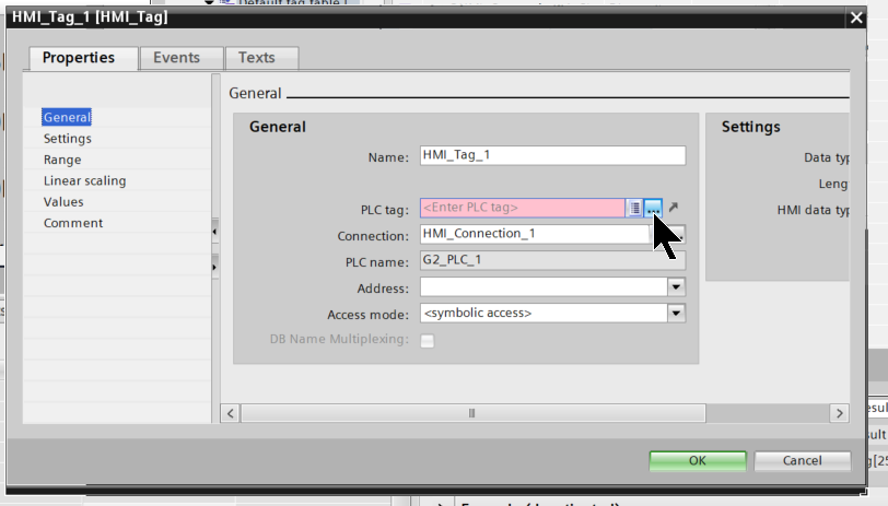
This time, click on the Create button and add a new Tag directly from its Tag Settings screen.
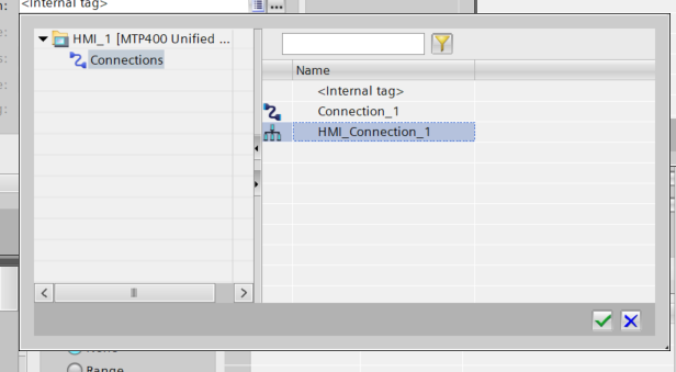
Click the … button in the Connection Field.
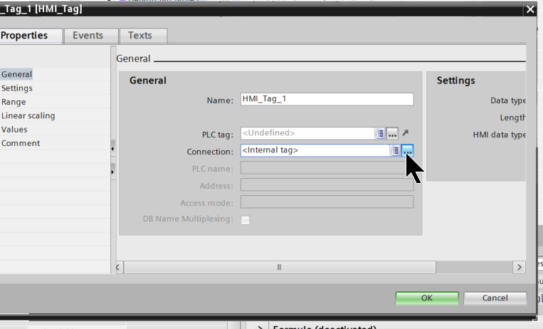
Select the HMI connection you just added.
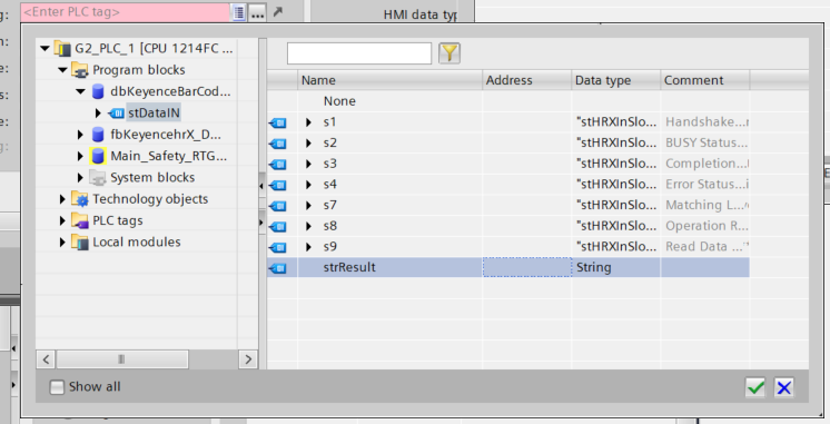
Next, click on the … button in the PLC tag column and select it as the Tag for the S71200 G2.
Here as an example we set the string stResult.
Done!
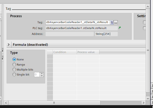
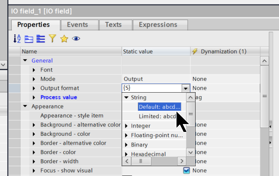
Finally, set String>Default to display a string in the Output format.
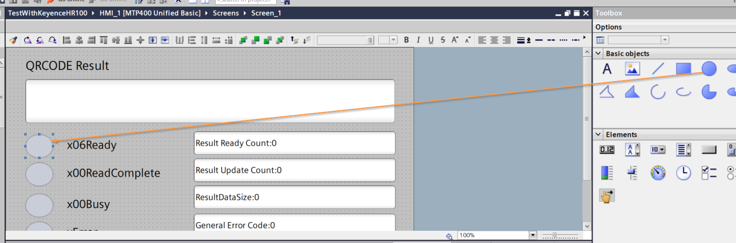
Add Lamp
Next, add Basic elements>Circle to add a lamp on the screen.
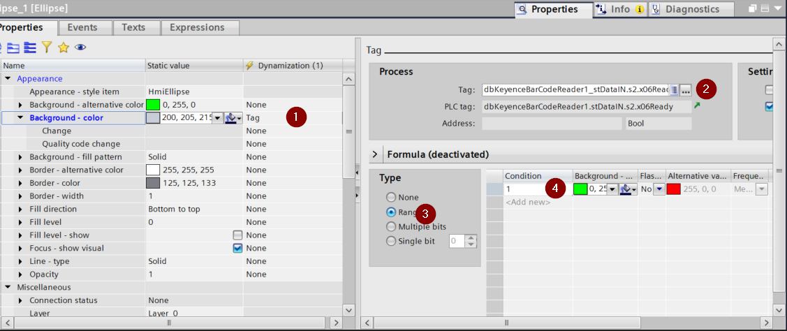
As before, set Dynamic(1) to Tag>Add Tag.Then select Range in the Type field.Finally, set the condition in Condition and change the color.This time, change the color to red for the Circle if the Tag value is 1.
Add text
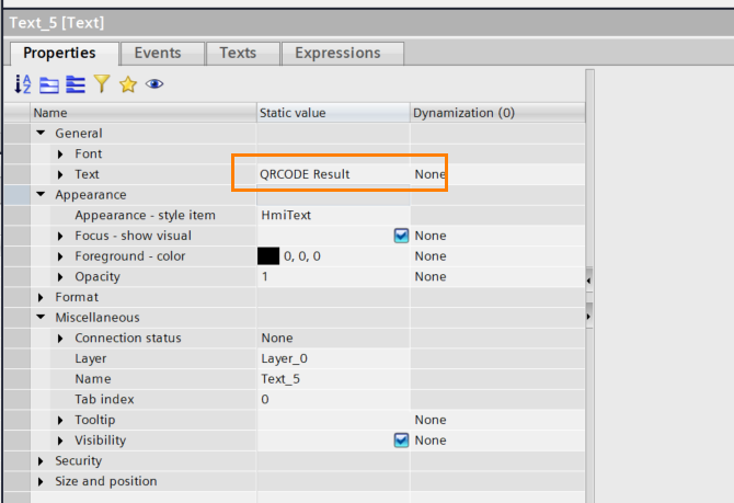
To add a QR Code title, let’s add Text to Basic Object.
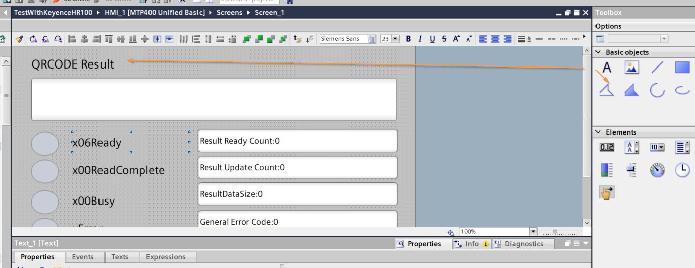
Set the text to be displayed in the Text field.
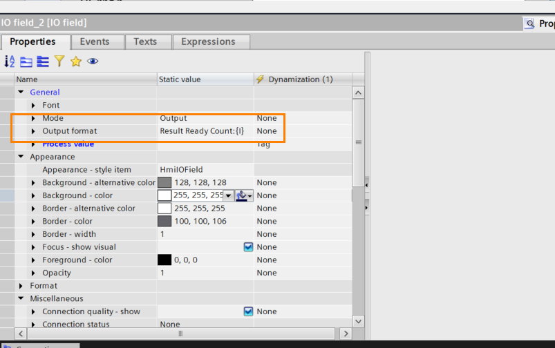
Add Default Text in I/O Field
If there are characters you want to display in the I/O Field by Default, don’t bother adding a Text Object.
Enter the appropriate I/O Field’s Property>Output format> character, and then set it to something like {i}.
Sync Tags
I just added a bunch of PLC Tags, but none of them are set up with proper names.Let’s use the PLC Tags Name Synchronization feature in WinCC then.
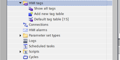
The button is shown below.This feature will cause PLC Tags to synchronize according to the name in the PLC.
Download
Hardware ConfigurationとプログラムをCPUにDownloadしてください。
Result
Done!Profinet communication was possible between S71200 G2 and HR-X100WB.
QR Code read from HR-X100WB was also confirmed on the S71200 G2.
Download the project for this article at this Link.
https://github.com/soup01Threes/Siemens/blob/main/TestWithKeyenceHR100.zap20
You can check the operation in this video.