This is a new series exploring various articles using Schmersal’s PSC1-C-100-FB1 Safety Controller. Episode 6 covers connecting to a Pilz door lock and using Terminal Input/Output.
Let’s enjoy Factory Automation !
Reference Video
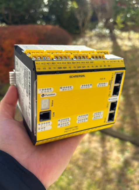
Schmersal.PSC1-C-100-FB1 開封しました!
Reference Link
http://soup01.com/ja/category/schmersal_jp/psc1/
Door Control
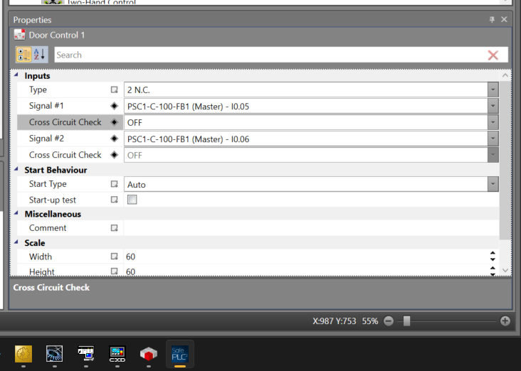
This is the connection type that can be configured for the Door Control component on SafetyPLC2.
Switch type | Connections | Description |
|---|---|---|
1 (2 N.C.) | NCx2 | Safety door monitoring |
2 (2 N.C. TimeMonitored) | NCx2+Time monitoring | Safety door monitoring + Time monitoring |
3 (1 N.O. 1 N.C.) | NOx1+NCx1 | Safety door monitoring |
4 (1 N.O. 1 N.C. Time Monitored) | NOx1+NCx1+Time monitoring | Safety door monitoring + Time monitoring |
5 (2 N.O. 2 N.C.) | NOx2+NCx2 | Safety door monitoring |
6 (2 N.O. 2 N.C. Time Monitored) | NOx2+NCx2+Time monitoring | Safety door monitoring + Time monitoring |
7 (3 N.C.) | NCx3 | Safety door monitoring |
8 (3 N.C. Time Monitored) | NCx3+Time monitoring | Safety door monitoring + Time monitoring |
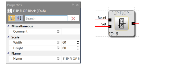
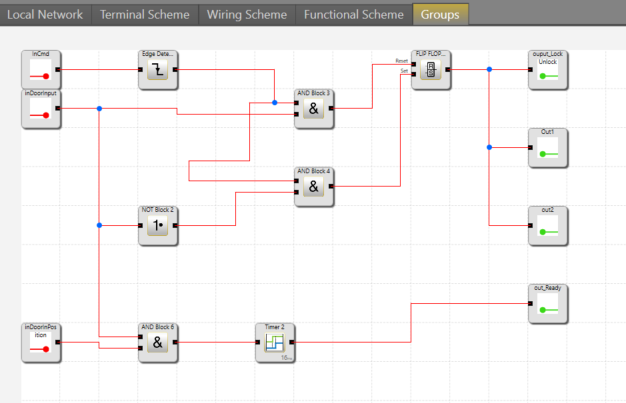
FLIP FLOP Block
The FLIP FLOP Block operates as follows:
- The result of the FLIP FLOP Block at initialization is “0”.
- When the edge of the Set input changes from “0” to “1”, the result becomes “1”.
- Even if the Set input state returns to “0”, the output remains “1”.
- When an edge change from “0” to “1” occurs on the Reset input, the result becomes “0”.
- Setting both inputs to “1” results in “0”.
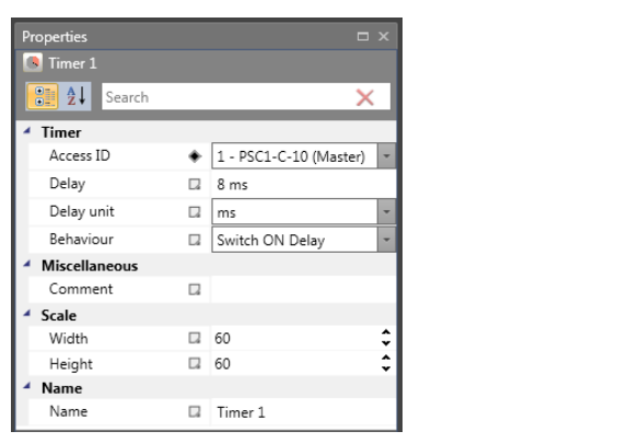
Timer
The Timer Block provides a logic result of “1” or “0” based on the specified time delay setting.
- Access ID: The timer number, which is automatically set when inserted into the program. If all timers are used up, the timer command in the menu becomes invalid.
- Delay: The time for which you want to operate the timer.
This is the timer setting range for the PSC-C-100-FB1:
- T min = Cycle time of PSC-C-100-FB1
- T max = 533 min (31999992 ms)
Note: Since the cycle time of the PSC1-C-10 module is fixed, the timer specifications must be as follows. For the PSC1-C-100, it must be a multiple of 16ms [24ms, 32ms].
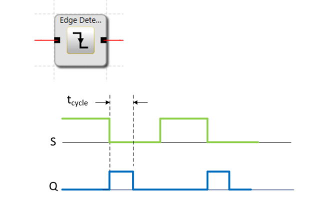
Edge detection
When the Edge detection block is set to detect the rising edge of an input signal, the device outputs a High pulse with a duration of 1 cycle. The falling edge is ignored, and a new High pulse is output only when the input signal changes from Low to High.
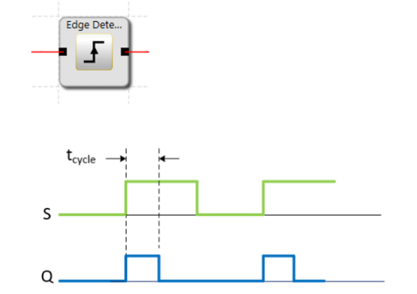
When the Edge detection block is set to detect the falling edge of an input signal, the device outputs a High pulse with a duration of 1 cycle. The rising edge is ignored, and a new High pulse is output only when the input signal changes from High to Low.
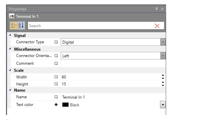
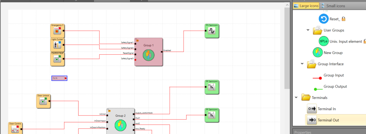
Terminals
Terminals are useful for the clear representation of functional schemes and can also be used to utilize signals on other sheets. You can also configure “Output/Input connection point” elements.
Implementation
This is the configuration for this article.
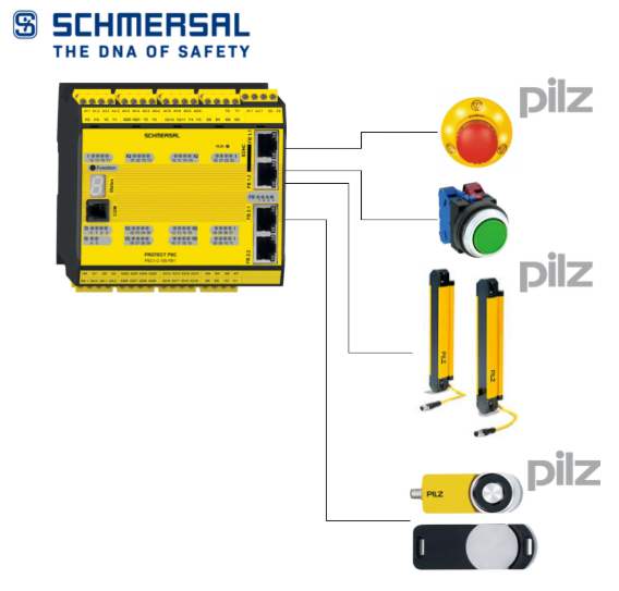
SCHMERSAL Side
This article is a continuation of Part 4.
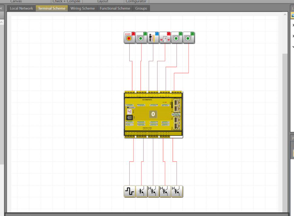
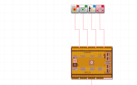
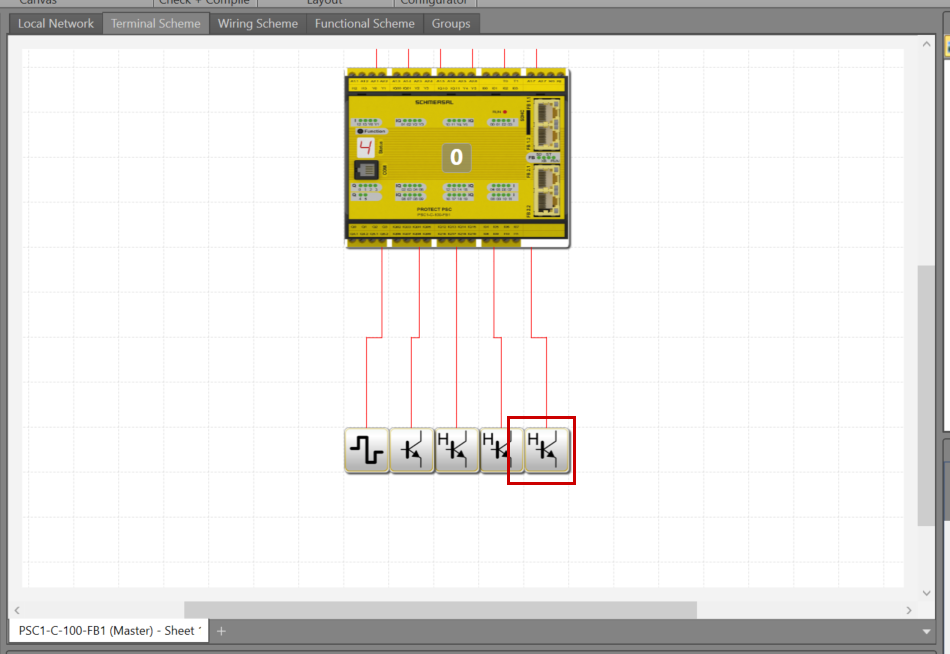
Terminal Scheme
These are the components defined in this article.
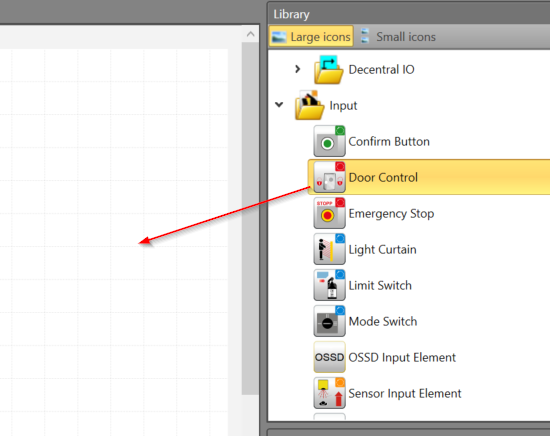
Add Door Control
Library>InputでDoor Control部品を追加します。
Add the Door Control component via Library > Input.
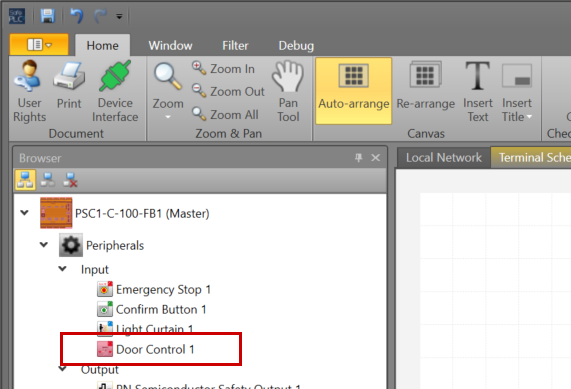
Done!
The Door Control component added previously is also displayed in Peripherals > Input.
Let’s set the appropriate parameters for the Door Control component.
Add Door Lock in position Input
Add an input component to detect that the Pilz door switch is in the closed position.
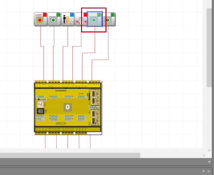
Add Door Unlock Button
Add an operation button to Lock or Unlock the Pilz door switch.
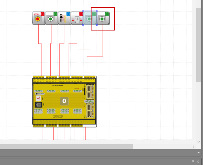
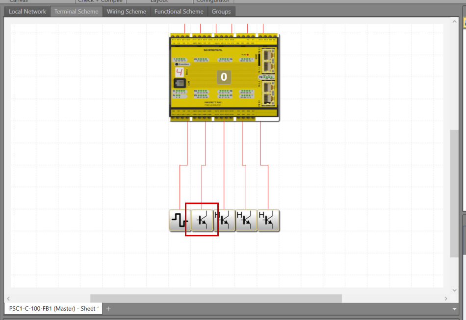
Add Door Safety Output
Add the Safety output for the Pilz door switch.
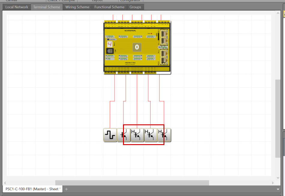
Add Door OK Lamp
This is a NonSafety output that only outputs when the Pilz door switch state is normal.
Add Door Unlock Output
This is the output used to Unlock/Lock the PILZ door switch.
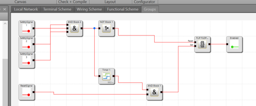
Program
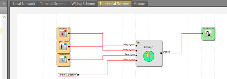
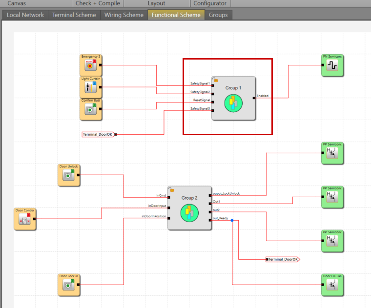
Next, we create the safety program. This time, we will create a separate Group to encapsulate the door lock logic.
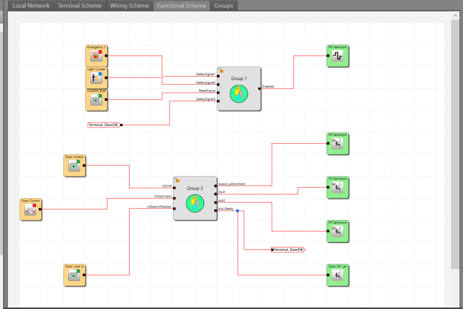
In this article, by using Terminal components, Functional Sheets become clearer.
Configure the signal you want to transfer with Terminal Out, and configure the same signal with Terminal In.
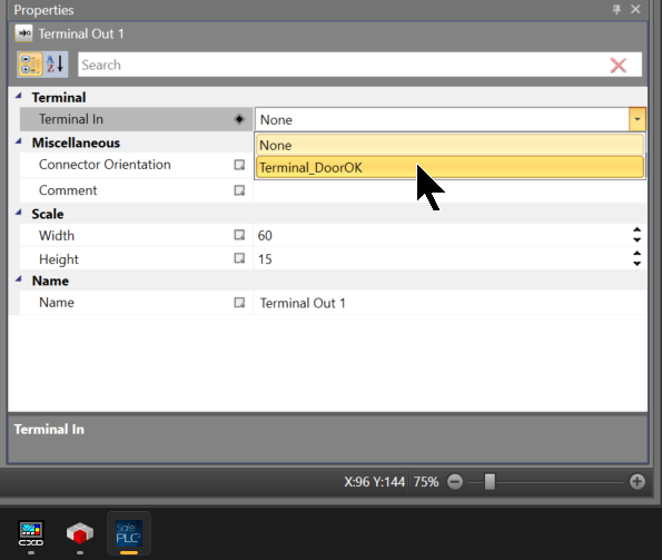
Use Terminal In just like any other component.
Next, let’s look at the door lock logic.
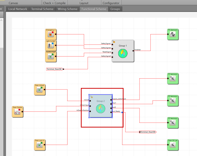
Every time the Unlock/Lock button is pressed, if the original state is Unlocked, it will Lock the door. If the original state is Locked, it will Unlock the door.
And if the door lock status is OK, Out_Ready is set to TRUE.
This time, we will edit the Group logic created in the Part 3 article.
Add another Terminal Input within the Group and connect it to the door lock normal signal.
Connect to the Controller
Connect the COM Port of the PSC1-C-100-FB1 to the PC using the dedicated cable.
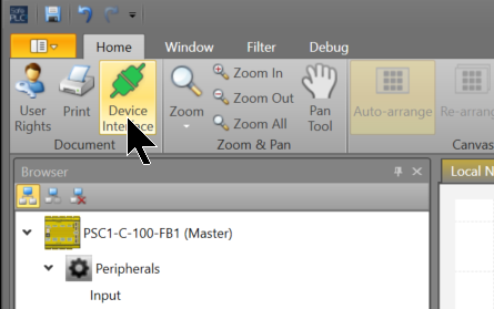
Click SafePLC2 > Home > Device Interface.
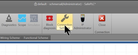
Click Connection Settings.
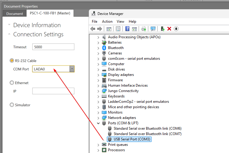
Since we are using an RS-232 cable this time, configure the COM Port to match the Device Manager.
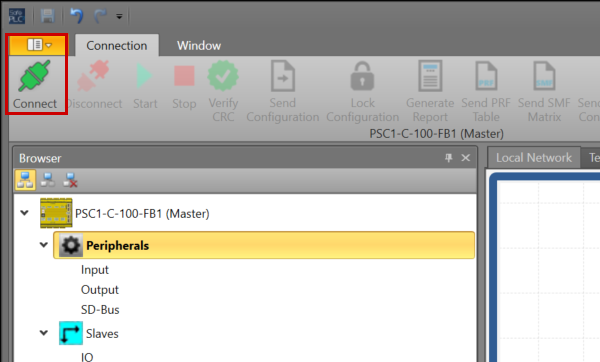
Finally, click the Connect button to connect the CPU and SafePLC2.
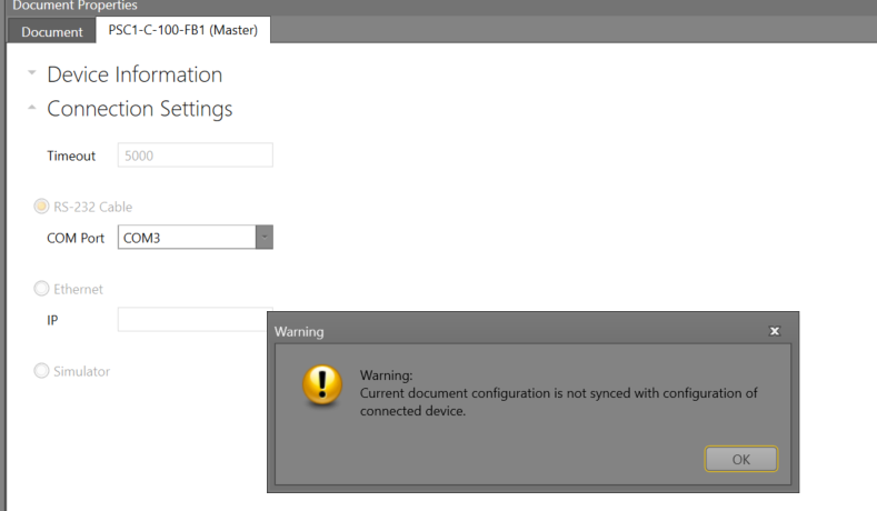
Proceed by clicking OK. With that, we have connected SafePLC2 and the PSC1-C-100-FB1.
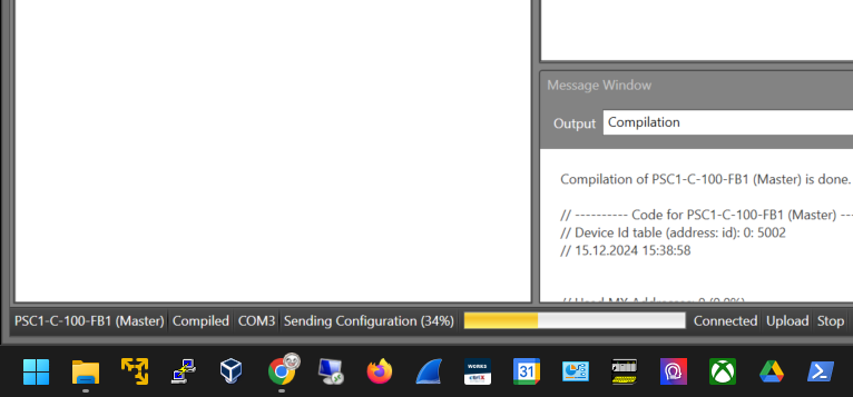
Send Configuration
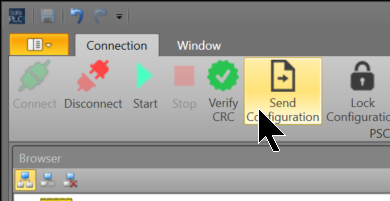
Click Send Configuration to transfer the project to the PSC1-C-100-FB1.
Please wait a moment…
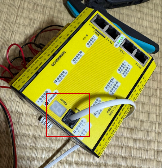
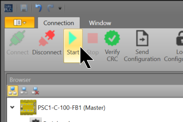
Start
Finally, click the Start button to put the PSC1-C-100-FB1 CPU into RUN MODE.
Result
Please check the operation in this video.