Schmersal PSC1 Safety Controller Part 7: Connecting via TwinCAT3 and EtherCAT
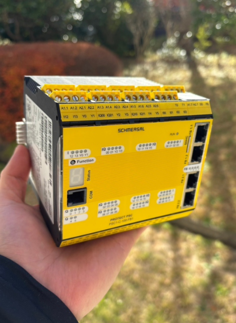
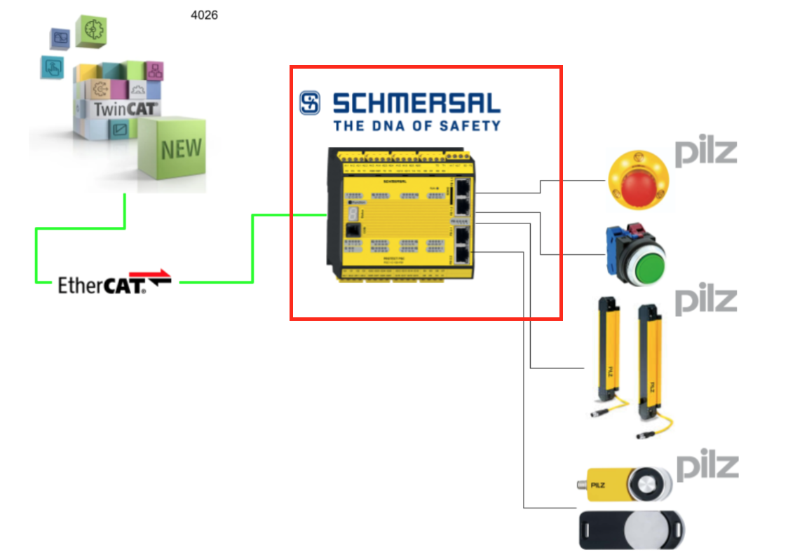
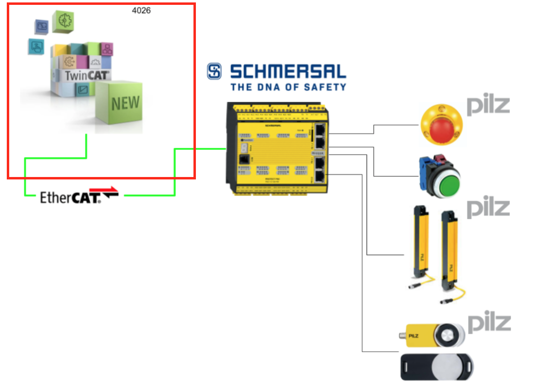
This is a new series exploring various articles using the Schmersal PSC1-C-100-FB1 Safety Controller. In Part 7, we will exchange data with Beckhoff TwinCAT3 via EtherCAT.
Let’s enjoy FA.
Reference Video
Reference Link
http://soup01.com/ja/category/schmersal_jp/psc1/
EtherCAT
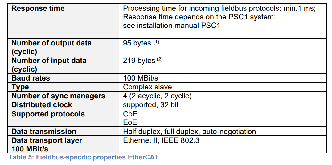
These are the EtherCAT Slave specifications for the Schmersal PSC1-C-100-FB1 Safety Controller.
Implementation
This is the structure of this article.

Schmersal Side
First, let’s configure the Schmersal side.
Configure EtherCAT Slave
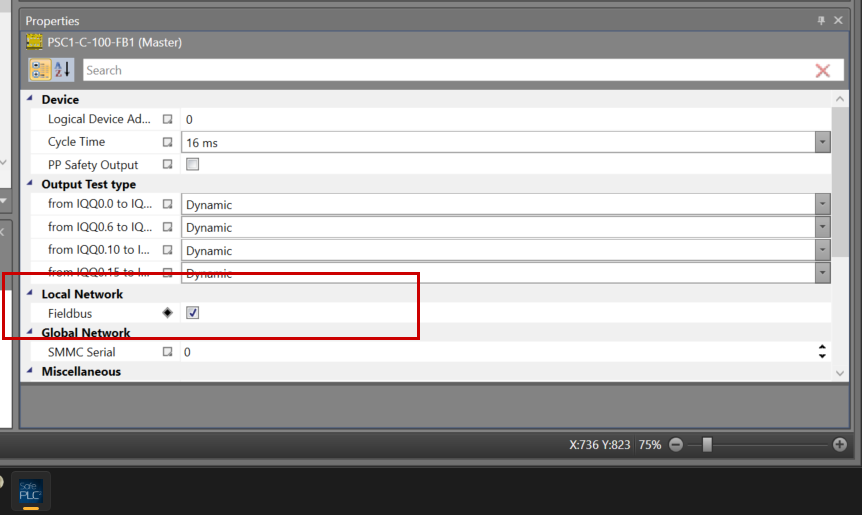
To enable the EtherCAT interface on the PSC1-C-100-FB1 Safety Controller, click on the controller.
In the Properties screen, check the box for Local Network > Fieldbus.
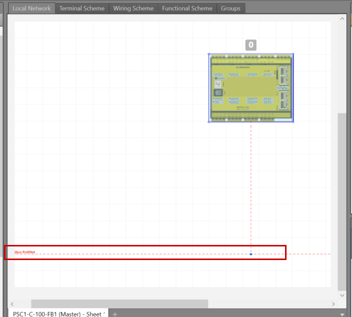
The Fieldbus display will appear in the Local Network tab of the project.
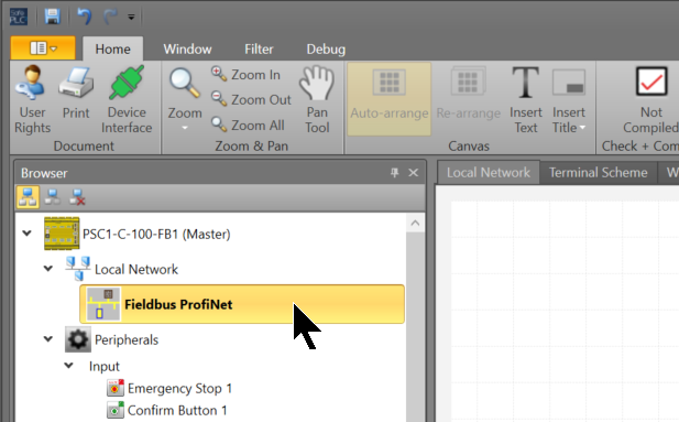
Next, click on Local Network > Fieldbus.
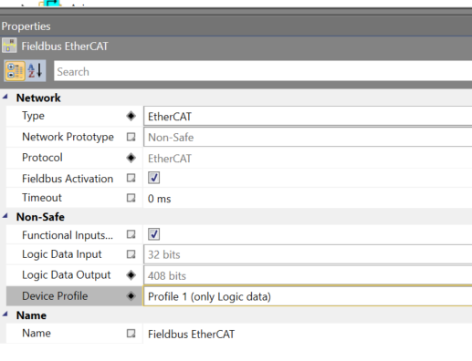
In Properties > Network > Type, set it to EtherCAT.
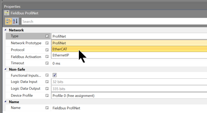
Done!
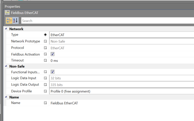
The device profile used in this article is Profile 1 (Only logic data).
Safety Program
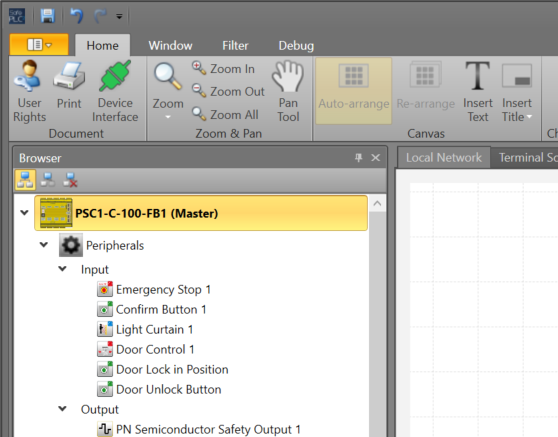
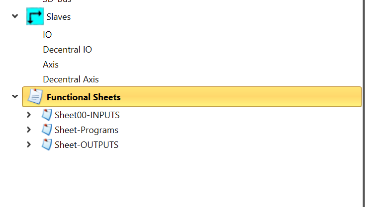
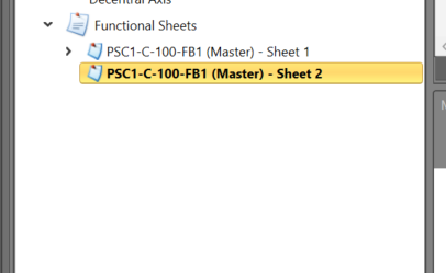
Next, create the safety program. Continuing from Part 6, create “Functional Sheets” for each function to organize the program clearly.
- Sheet00-INPUTS: Sheet to organize input data.
- Sheet-Programs: Sheet containing logic such as Door Lock.
- Sheet-OUTPUTS: Sheet to organize outputs.
To add a sheet, right-click on Functional Sheets > Add New Sheet.
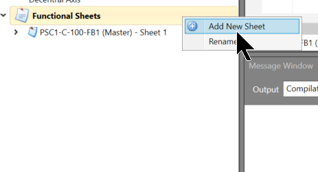
Done!
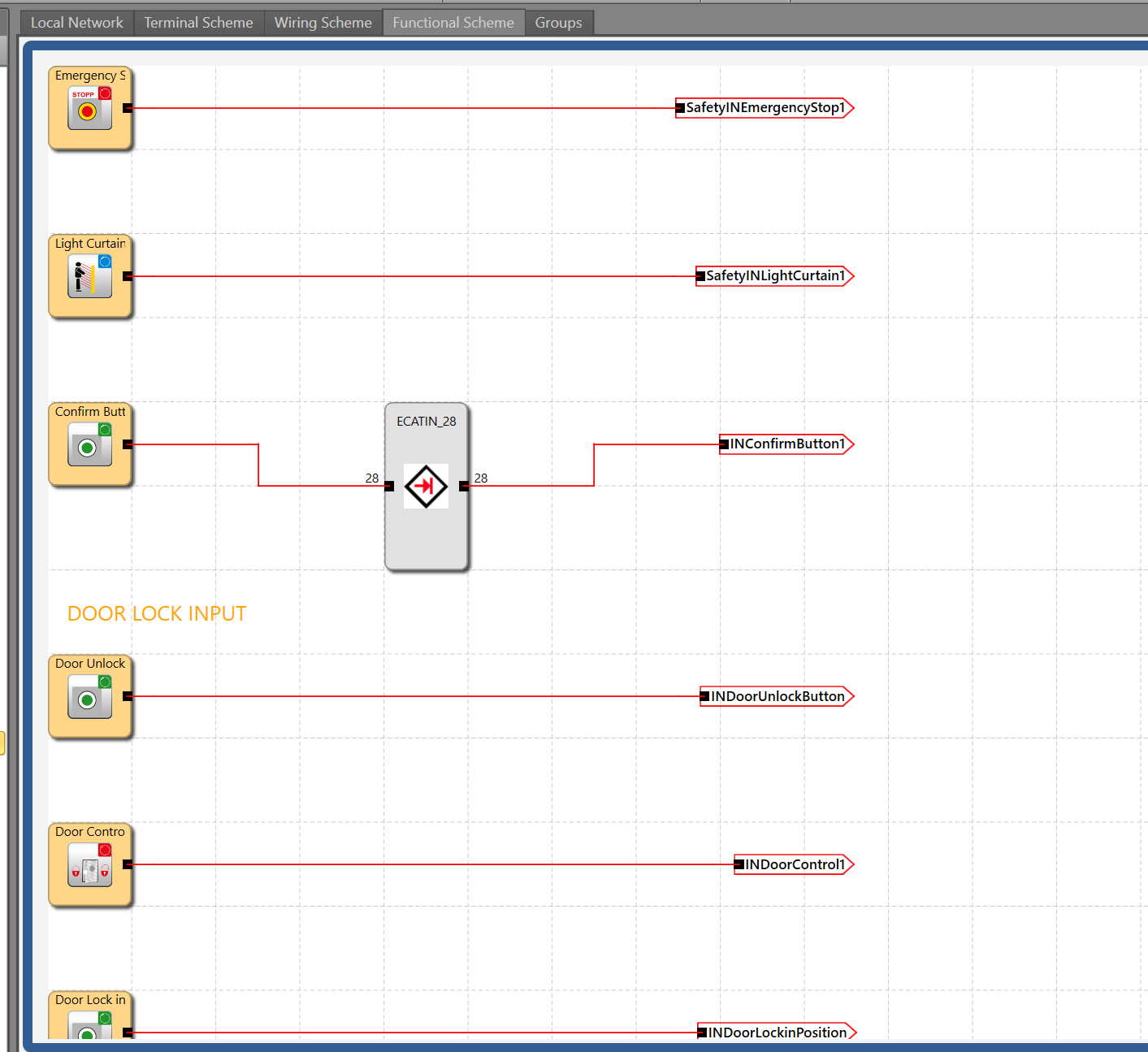
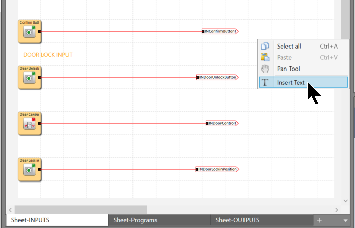
Sheet-INPUTS
Sheet-INPUTS forwards each safety/non-safety input/output and the reset-capable signal received via EtherCAT Fieldbus to different terminals.
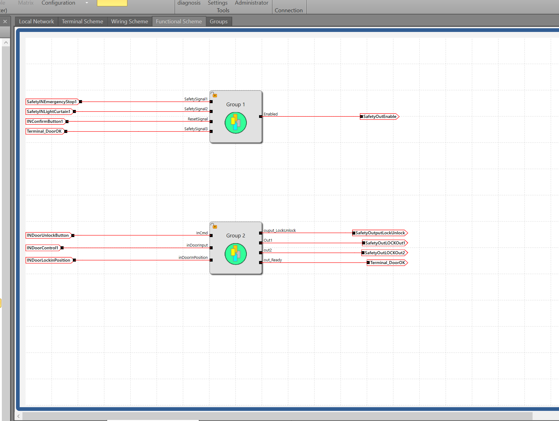
Sheet-Programs
Sheet-Programs uses the terminals forwarded from the safety inputs to execute different safety logic. It also forwards output data to the terminals.
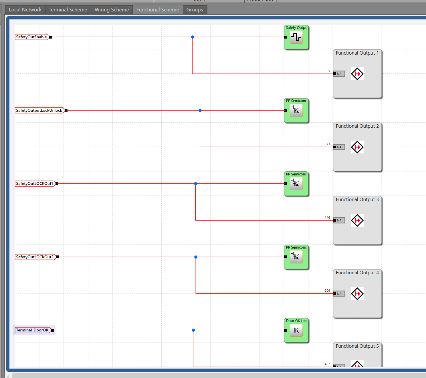
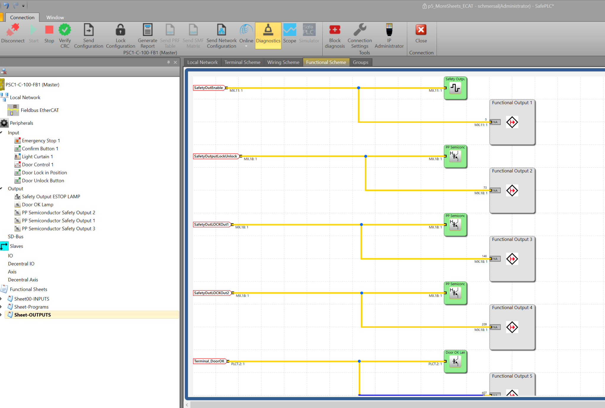
Sheet-Outputs
Sheet-Outputs controls the outputs connected to the safety controller and sends them to the Beckhoff TwinCAT3 via the EtherCAT network.
Add Comments
If you want to add comments to your program in the SafePLC2 tool, right-click in an empty space on the sheet and select “Insert Text.”
Connect to the Controller
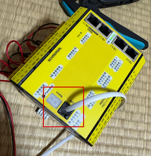
Connect the COM port of the PSC1-C-100-FB1 to your PC using the dedicated cable.
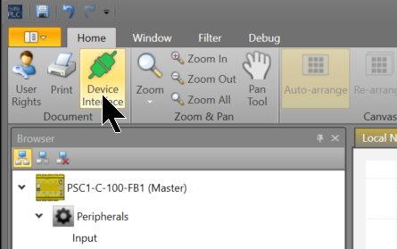
Go to SafePLC2 > Home > Device Interface.
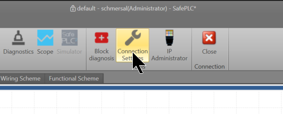
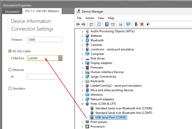
Click “Connection Settings.”
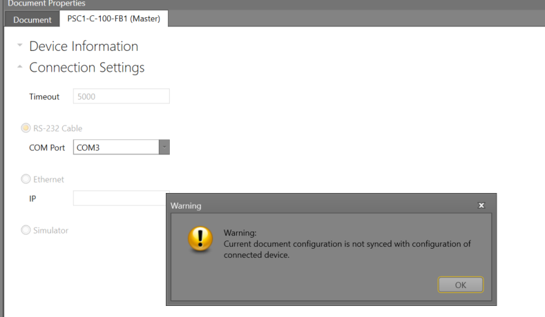
Since we are using an RS-232 cable this time, configure the COM port to match the Device Manager.
Finally, click the “Connect” button to connect the CPU and SafePLC2.
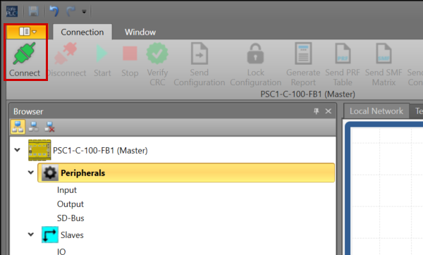
Proceed with OK. You are now connected to the PSC1-C-100-FB1 with SafePLC2.
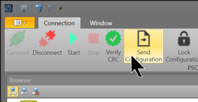
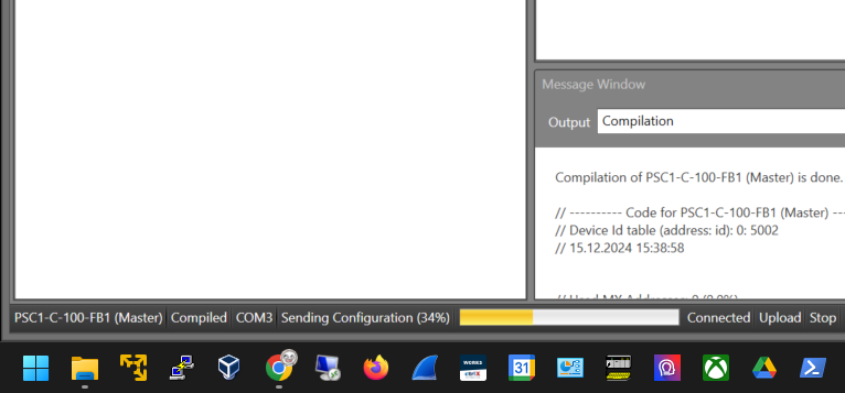
Send Configuration
Click “Send Configuration” to transfer the project to the PSC1-C-100-FB1.
Please wait a moment…
Beckhoff Side
Next, let’s configure the Beckhoff side.
Download ESI File
To build an EtherCAT network, download the ESI (EtherCAT Slave Information) file from the Schmersal website.
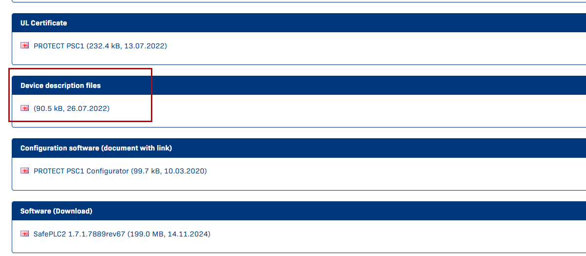
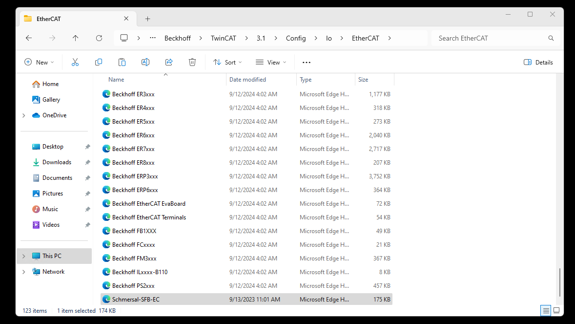
Store the downloaded ESI file in the following directory:
(I am using TwinCAT3 4026)
C:\Program Files (x86)\Beckhoff\TwinCAT\3.1\Config\Io\EtherCAT
Reload ESI File
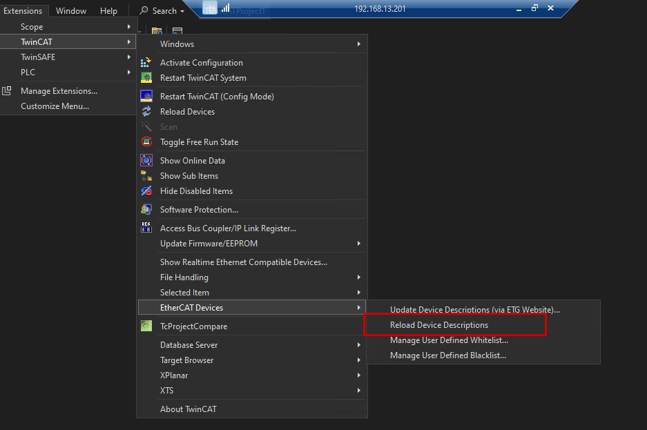
Launch TwinCAT3, and go to Extensions > TwinCAT > EtherCAT Devices > Reload Device Descriptions to reload the ESI file.
Add New Project
Launch TwinCAT 4026 and create a new project via File > New > Project.
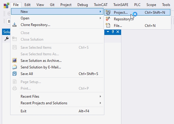
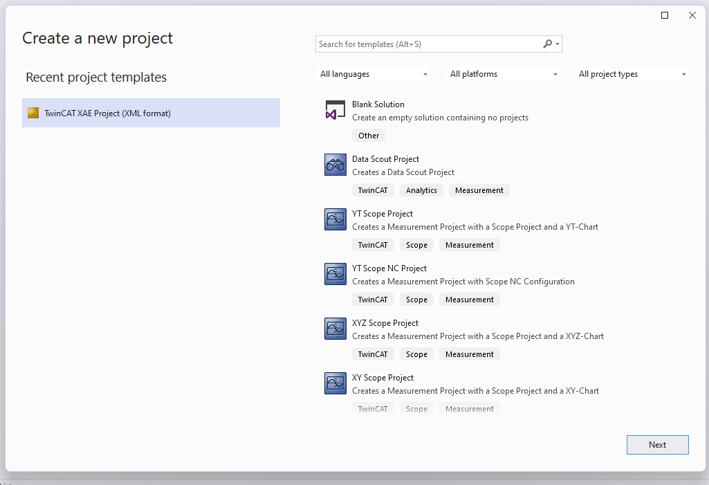
Select “TwinCAT XAE Project” and proceed with “Next.”
Set the project name and proceed with “Create.”
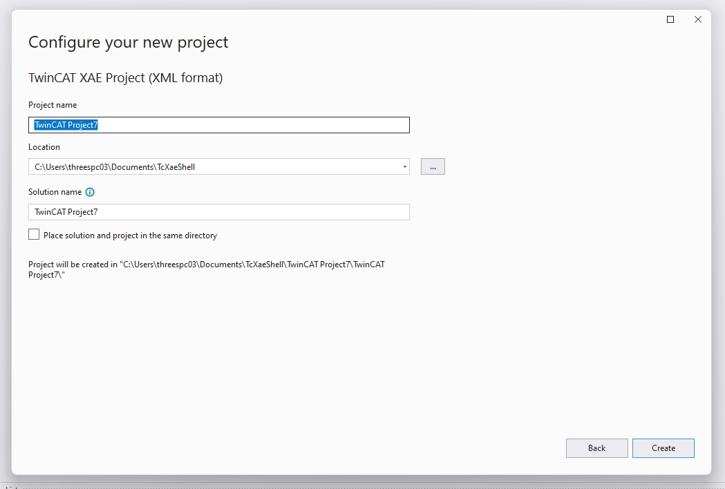
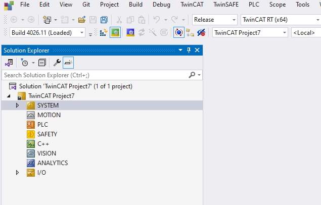
Done! The TwinCAT project has been created.
Add EtherCAT Master
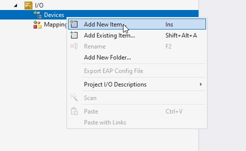
To add an EtherCAT Master, right-click on Device > Add New Item.
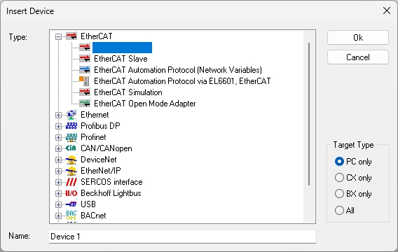
Add EtherCAT > EtherCAT Master.
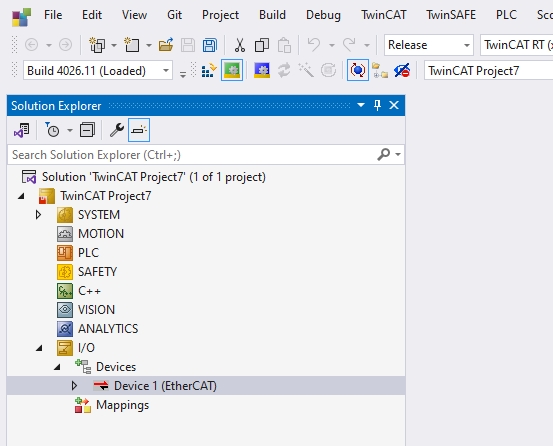
Done! The EtherCAT Master has been added.
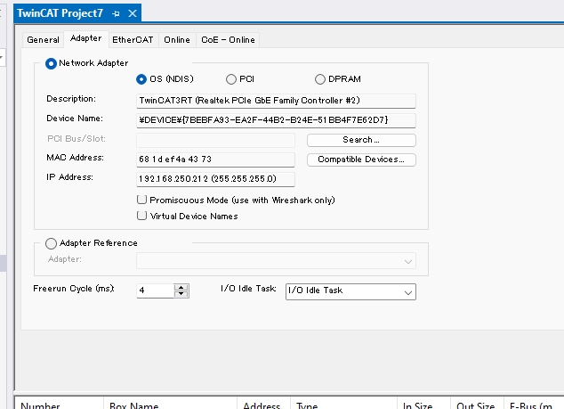
Configure Adapter
Open the Adapter tab to configure the Ethernet adapter to be used as the EtherCAT Master.
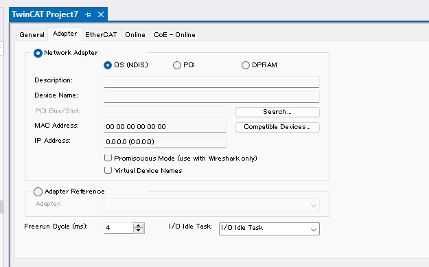
Searchをクリックし、実際に使用するEthernet Adapterを設定しましょう。
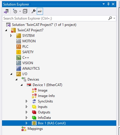
Scan Network
Right-click on the EtherCAT Master > Scan to search for EtherCAT slaves on the network.
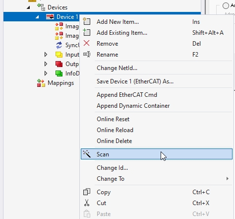
Done! The PSC-C-100-FB1 controller used in this article was found.
Add PLC
Next, right-click on PLC > Add New Item to add a PLC project.
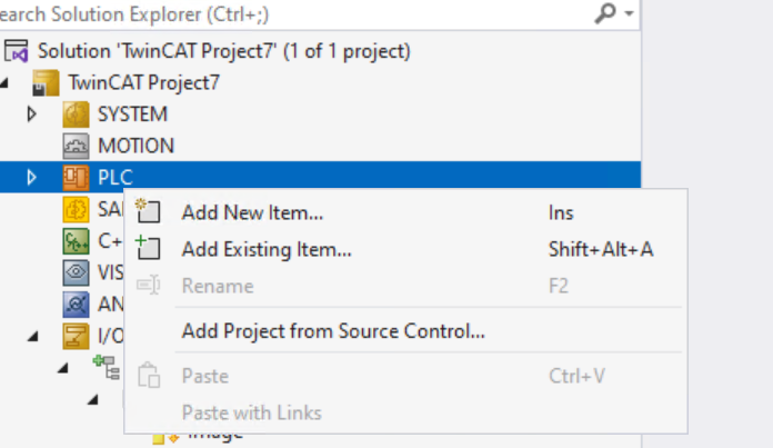
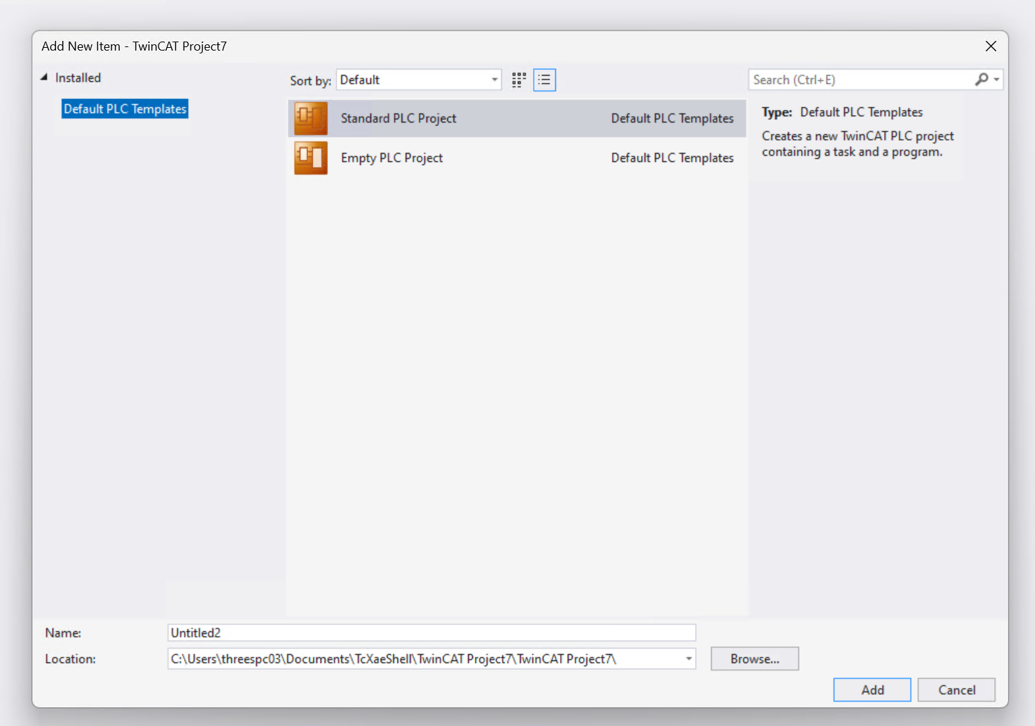
Select “Standard PLC Project” > Add.
DUT
Define a structure (DUT) to organize the PSC1 data.
DUT_PSC1_IN
This is the structure organizing the input data of the Schmersal PSC1 controller.
TYPE DUT_PSC1_IN :
|
|---|
DUT_PSC1_OUT
This is the structure organizing the output data of the Schmersal PSC1 controller.
TYPE DUT_PSC1_OUT :
|
|---|
DUT_PSC1
This is the structure combining the input and output data defined earlier.
TYPE DUT_PSC1 :
|
|---|
GVL
Next, create variables using the structures defined earlier in the Global Variable List (GVL).
{attribute ‘qualified_only’}
|
|---|
FB_PSC
This Function Block can encode the data of the Schmersal PSC-C-100-FB1.
FUNCTION_BLOCK FB_PSC
|
|---|
//AlwaysOn from PSC
|
|---|
MAIN
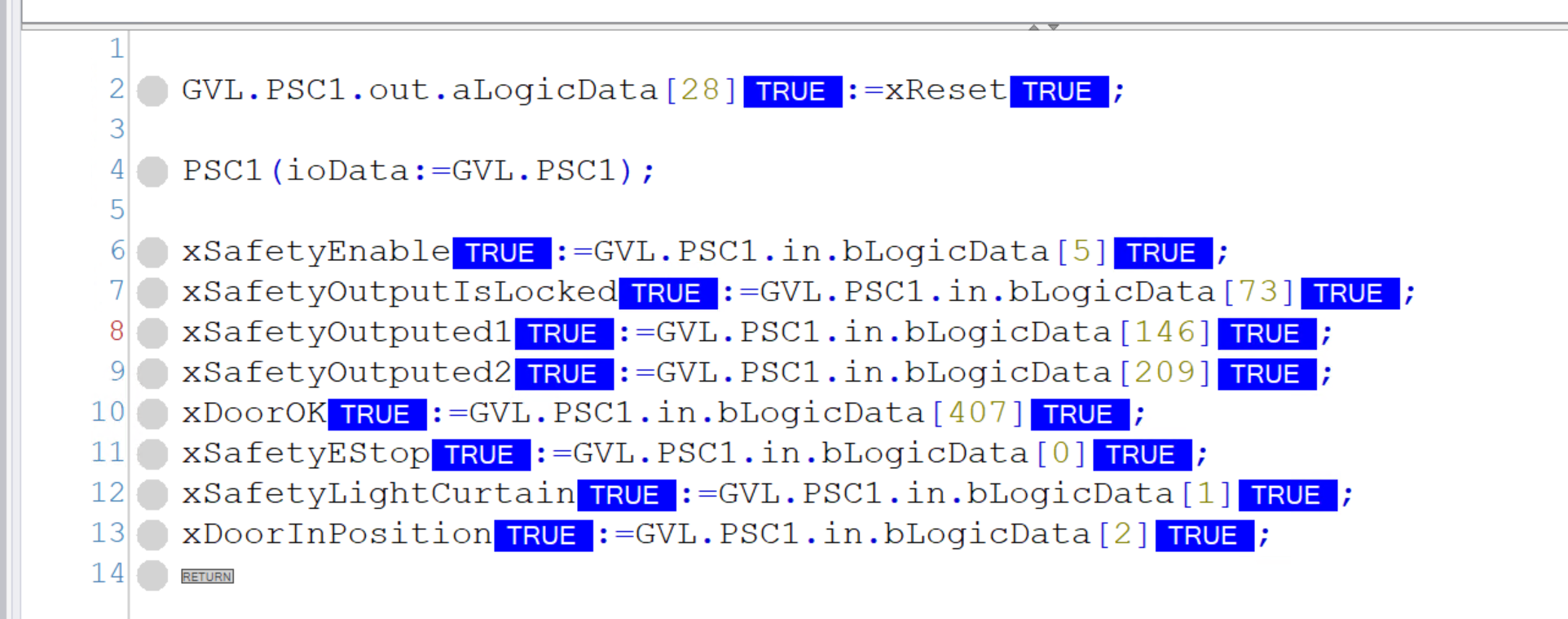
Finally, in the MAIN program, define an instance of FB_PSC to allow sending and receiving status such as emergency stop and reset signals to/from the Schmersal PSC-C-100-FB1.
PROGRAM MAIN
|
|---|
GVL.PSC1.out.aLogicData[28]:=xReset;
|
|---|
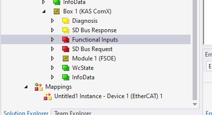
Mapping
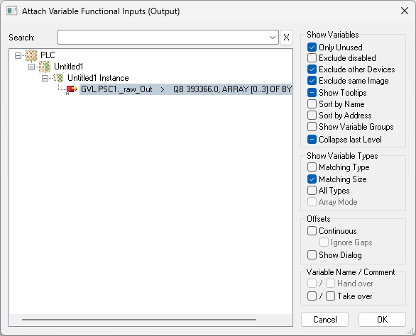
Map the Process IO data between the PSC-C-100-FB1 and TwinCAT3. Functional Inputs are outputs, and Diagnosis is the input. Click on Functional Inputs.
Right-click on Functional Inputs > Change Link.
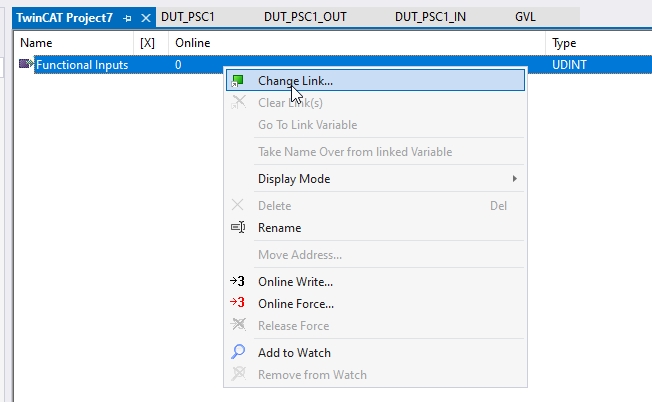
Link it to the variable defined in GVL earlier.
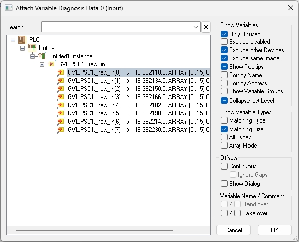
For the input data side, we will only use the first 0-55 bytes this time, so select Diagnosis Data 0 and Diagnosis 1 > Change Link.
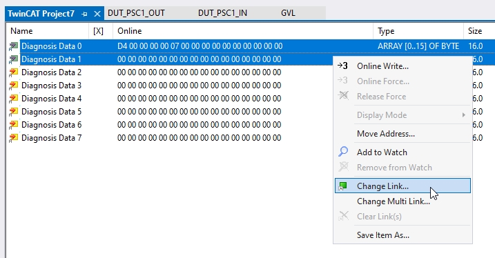
Link it to the variable defined in GVL earlier.
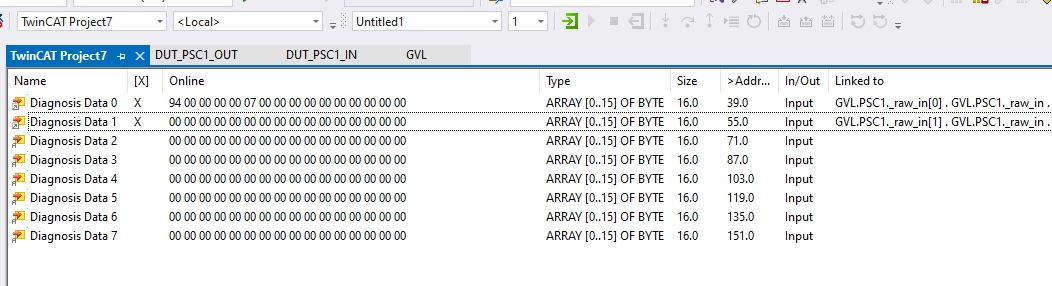
Done!
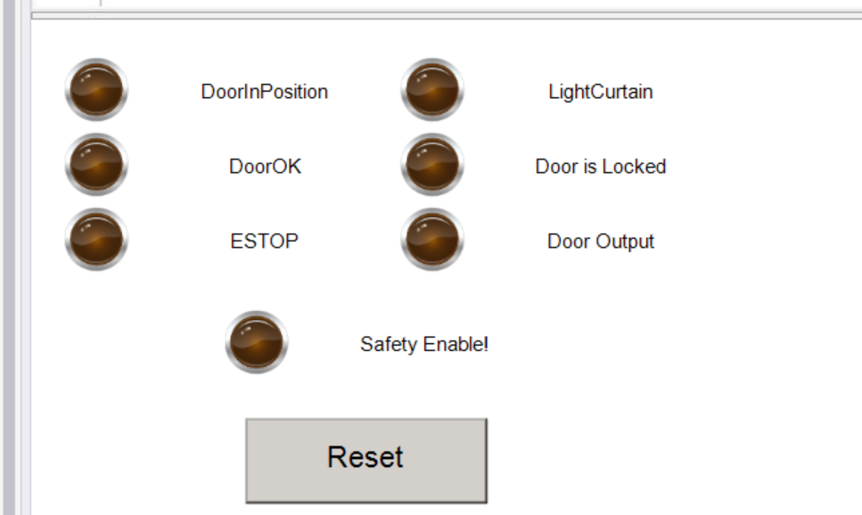
Visualization
Create a simple web screen to check communication with the PSC-C-100-FB1.
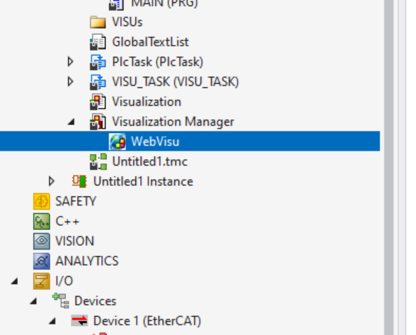
Add Web Visualization
In this article, we will access the Beckhoff TwinCAT3 Web HMI via a browser, so add “WebVisu” under the Visualization Manager.
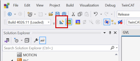
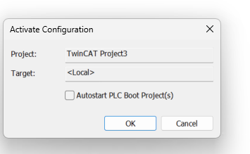
Active Configuration
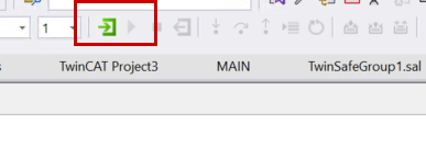
Download the TwinCAT project to the PLC.
Proceed with OK.
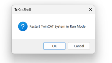
Switch TwinCAT3 to Run Mode.
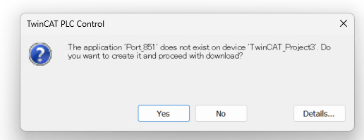
Login
Use “Login” to download the program.
Proceed with Yes.
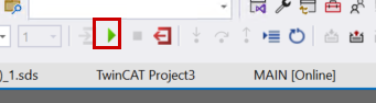
Finally, click the “Play” button to start the PLC program.
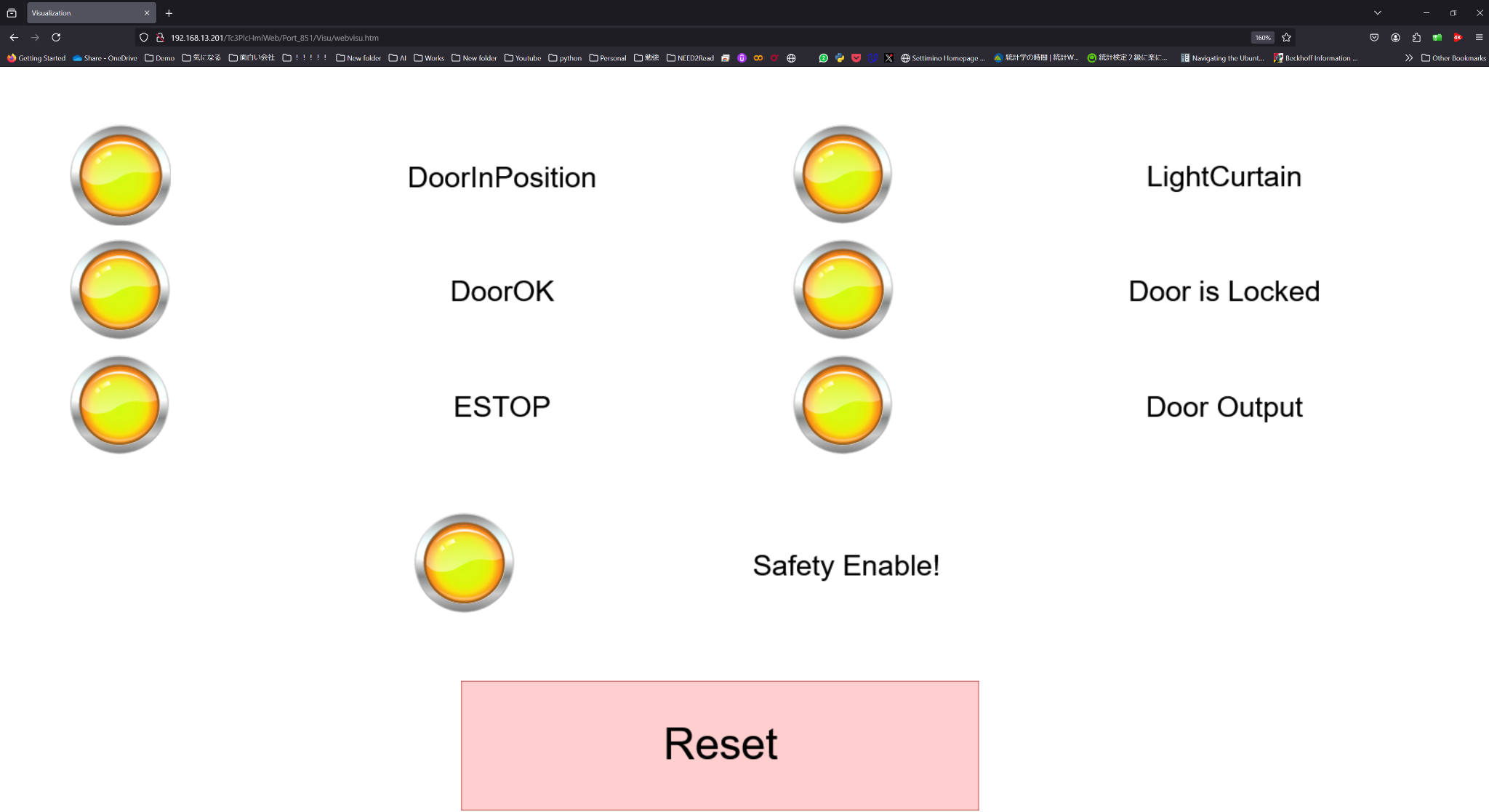
Result
The Schmersal PSC-C-100-FB1 Safety Controller is outputting the status of safety devices such as emergency stops.
The TwinCAT3 side has received those data, and we were also able to send the reset permission signal.
You should be able to access the Beckhoff TwinCAT3 Web HMI from a browser by changing the IP address in the link below to your TwinCAT3 PC’s IP address:
https://TwinCAT3 IP Address/Tc3PlcHmiWeb/Port_851/webvisu.htm
Please check the operation in this video:
Schmersal.PSC1-C-100-FB1 with TwinCAT3 via EtherCAT Communication
You can download the project created in this article via this link:
https://drive.google.com/file/d/1_Ic7vMHdk_tnWtKYgCNFSfBsQIJhiAk4/view?usp=sharing