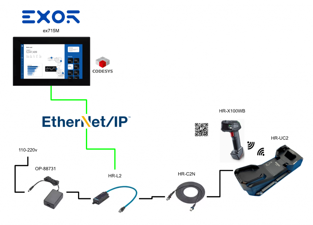
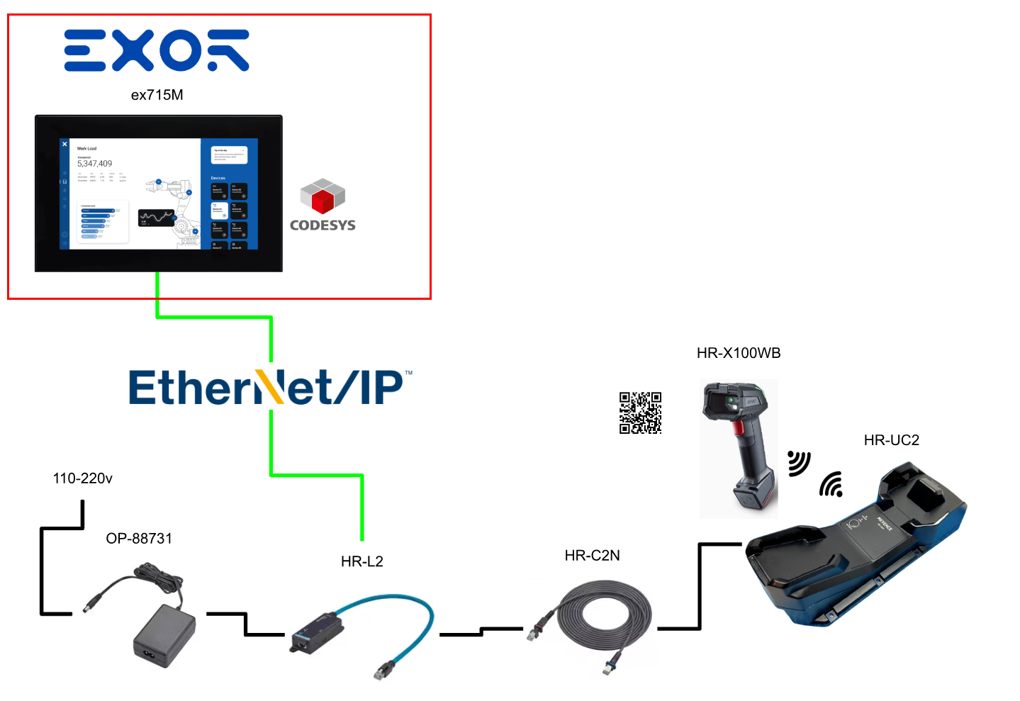
In this article, we will install Codesys on EXOR’s ex715M and communicate with KEYENCE’s HR-X100WB via EtherNet/IP.
Now, let’s enjoy Factory Automation!
Reference Link
EtherNet/IP?
EtherNet/IP is an industrial communication network managed by ODVA (Open DeviceNet Vendor Association, Inc). EtherNet/IP communication can share the network with standard Ethernet communication.

Cyclic and Message Communication
EtherNet/IP includes cyclic communication (implicit messaging) for periodically sending and receiving data, and message communication (explicit messaging) for arbitrarily sending and receiving commands and responses. Network load can be adjusted by setting the Requested Packet Interval (RPI) in order of priority.
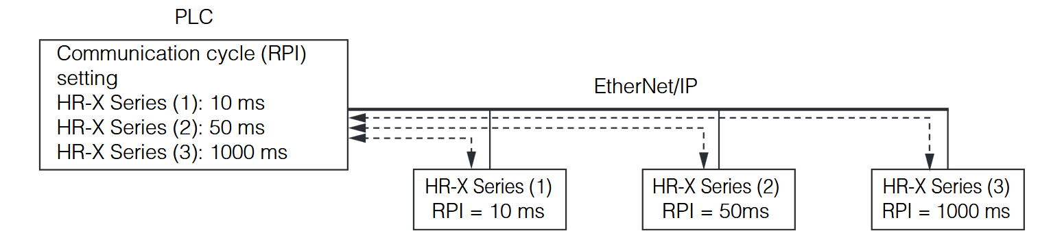
This communication allows checking the communication status by setting bits ON/OFF. Communication settings such as communication cycle and data size are configured on the PLC side. In networks connecting many devices including EtherNet/IP equipment with high load, delays or packet loss may occur. Please conduct sufficient verification before operation.
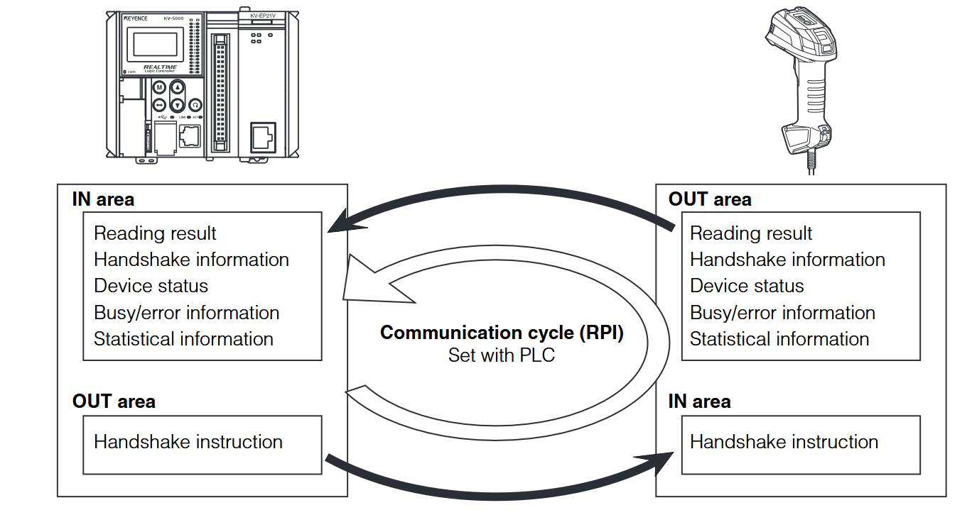
Connection type
During EtherNet/IP cyclic communication, a connection from the PLC to the HR-X series is opened. The available connection types depend on the device. Below are the connections available for the HR-X series.
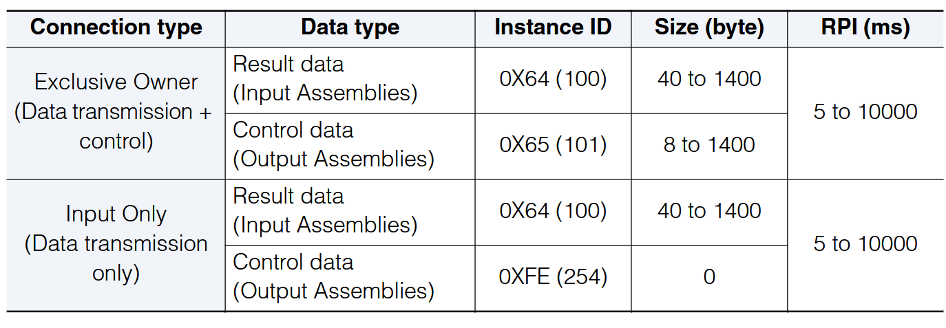
Exclusive Owner
Used for data transmission from the HR-X series as well as sending control commands from the PLC to the HR-X series.
- HR-X series -> PLC: Data transmission
- PLC -> HR-X series: Control commands
- A single HR-X series device cannot accept multiple “Exclusive Owner” connections.
Input Only
Used only for data transmission from the HR-X series. Multiple connections can be used with a single HR-X series device. (Up to 16 connections max)
- HR-X series -> PLC: Data transmission
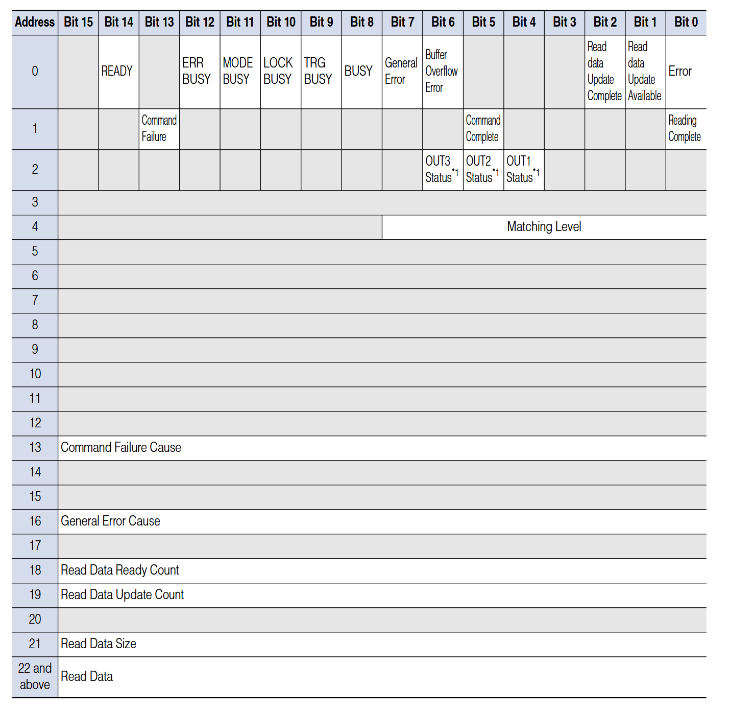
Result data (Input Assemblies)
Input Assemblies write responses from the HR-X series to the PLC. When using this device, the functions of each device are assigned as follows. Device status, result data, etc., are written to the Input Assembly.
The figure below shows the memory map of the Input Assembly (Instance ID: 0x64).
(HR-X -> PLC)
Control data (Output Assemblies)
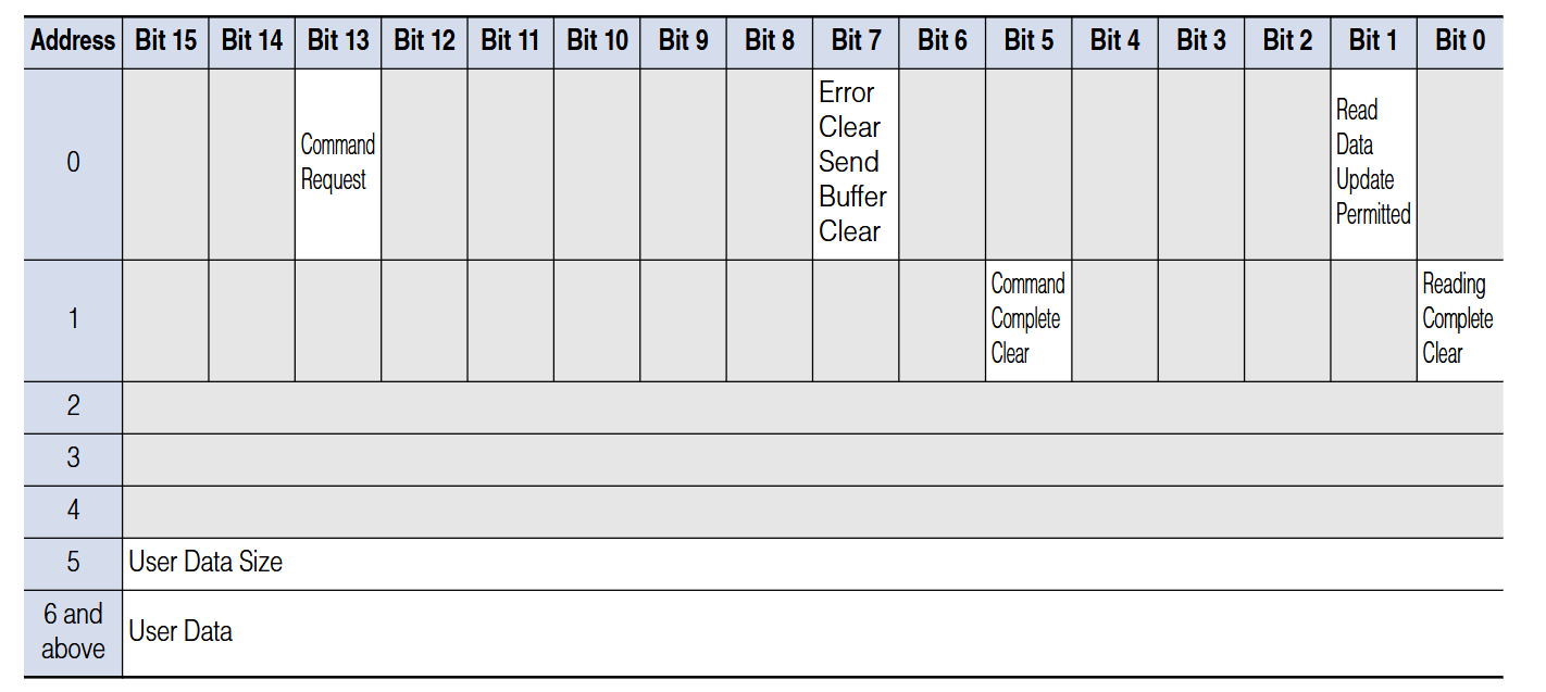
Output Assemblies write commands from the PLC to the HR-X series. When using this device, functions of each device are assigned as follows. Output Assemblies handle device control instructions, error clearing, handshake processing, etc.
The figure below shows the memory map of the Output Assembly (Instance ID: 0x65).
(PLC → HR-X)
Message Communication
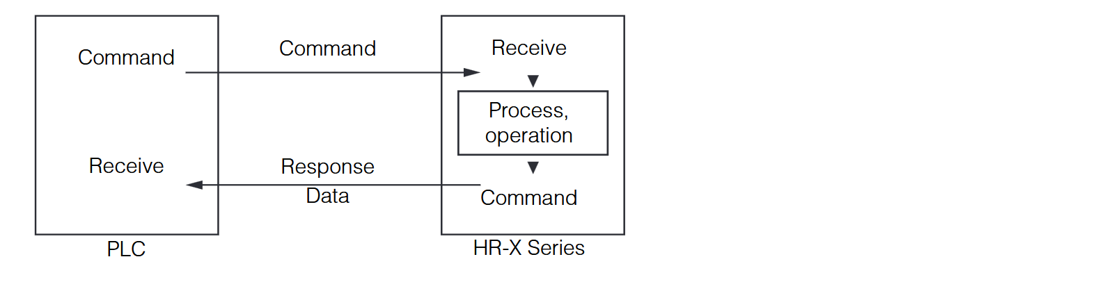
In message communication, commands and responses are exchanged.
Specifications
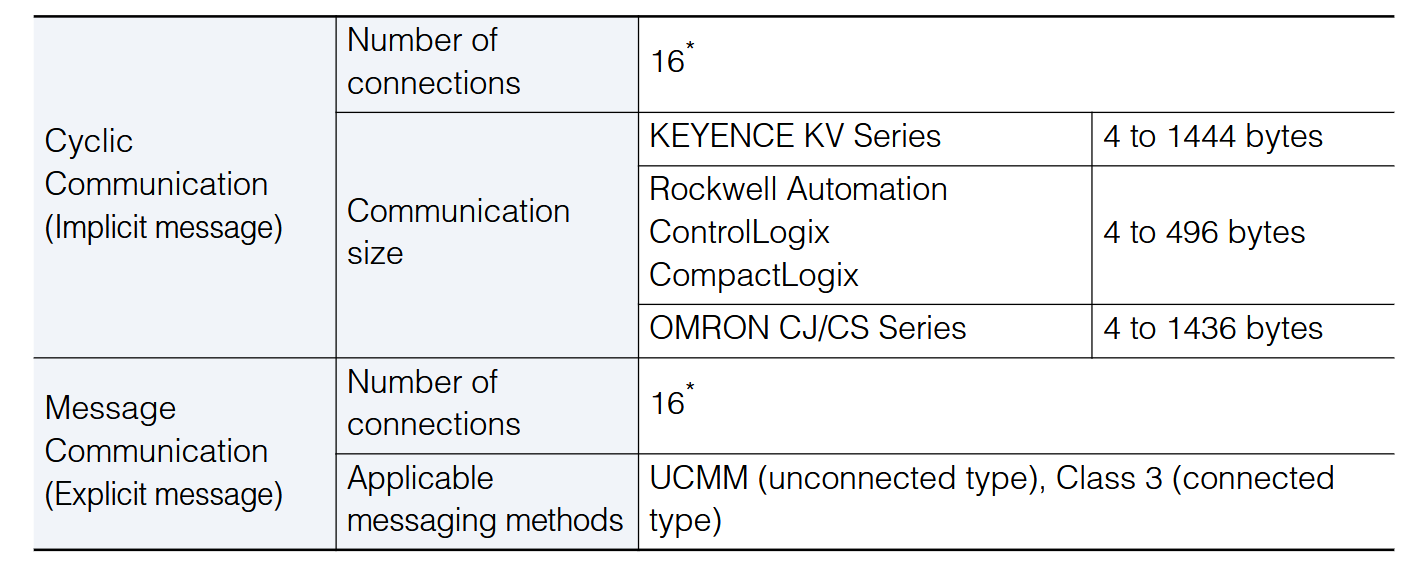
These are the communication specifications for the HR-X100WB. Note that the 16 connections limit includes both cyclic communication and message communication combined.
EXOR?
EXOR International, operating globally from Italy, has designed, developed, and manufactured HMI, control, and Industrial IoT solutions for nearly half a century. EXOR provides customers with easy-to-use tools that embody advanced technologies tailored for Industry 4.0 concepts.
Founded in Verona in 1971, it now has 150 employees across Italy, Germany, the United States, and India.

ex715M?
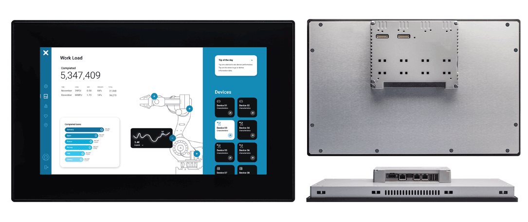
The eX715M touchscreen panel is a complete solution for system integration due to its versatility as an HMI, gateway, and PLC. The basic product concept enables proper and easy implementation of IIoT while complying with Industry 4.0 requirements. Powered by a high-performance 64-bit quad-core CPU, it runs JMobile applications in an optimal environment to deliver maximum performance.
The eX700M features a powerful 64-bit quad-core CPU that executes JMobile applications in an optimal environment for maximum performance.
The power of the eX700M is the best way to utilize the new graphic and security features of JMobile 4.5, in addition to excellent communication capabilities such as OPC UA Client/Server and MQTT.
Furthermore, the eX700M is ideal for IIoT edge applications requiring powerful, high-performance HMIs close to human operators in factories, marine environments, and building automation.
- Multi-touch display with robust glass front
- Wide range of certifications for harsh working environments, marine, and industrial use
- Supports installation of CODESYS PLC runtime software with full selection of network stacks for I/O
- 15.6-inch TFT projected capacitive touchscreen
- Multi-touch operation
- 64-bit quad-core CPU
- Operating temperature: -20°C to +60°C
- Fast system and project startup
- CODESYS V3 with Ethernet I/O stack
- Resistant to scratches, UV rays, and chemicals
- Network isolation capable using up to 3 Ethernet ports
- Networks with different IP addresses
- Plug-in modules for system expansion
Implementation
Keyence Side
First, we configure the KEYENCE HR-X100WB side.
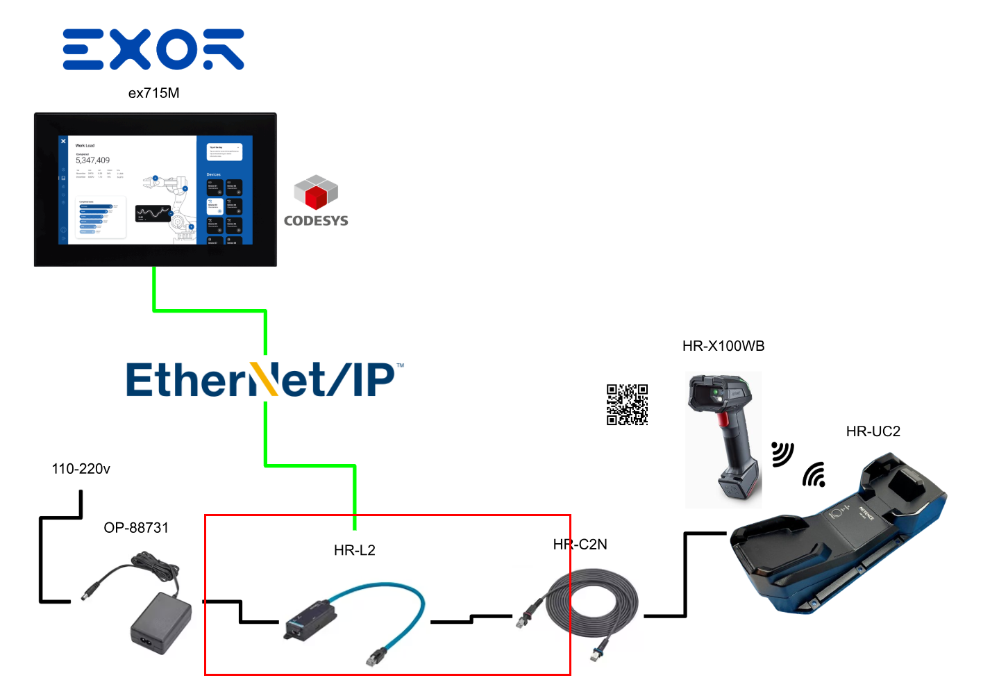
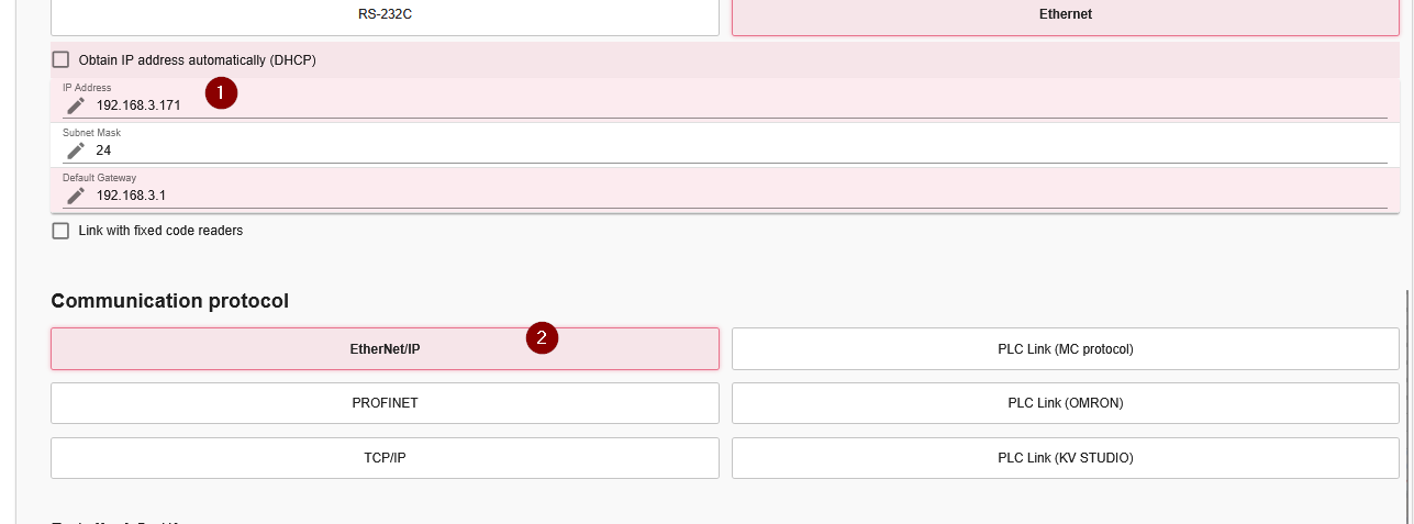
Set an appropriate IP address on the KEYENCE HR-L2 side, and set the Communication protocol to EtherNet/IP.
Codesys Side
Next, configure the Codesys side.
Download EDS File
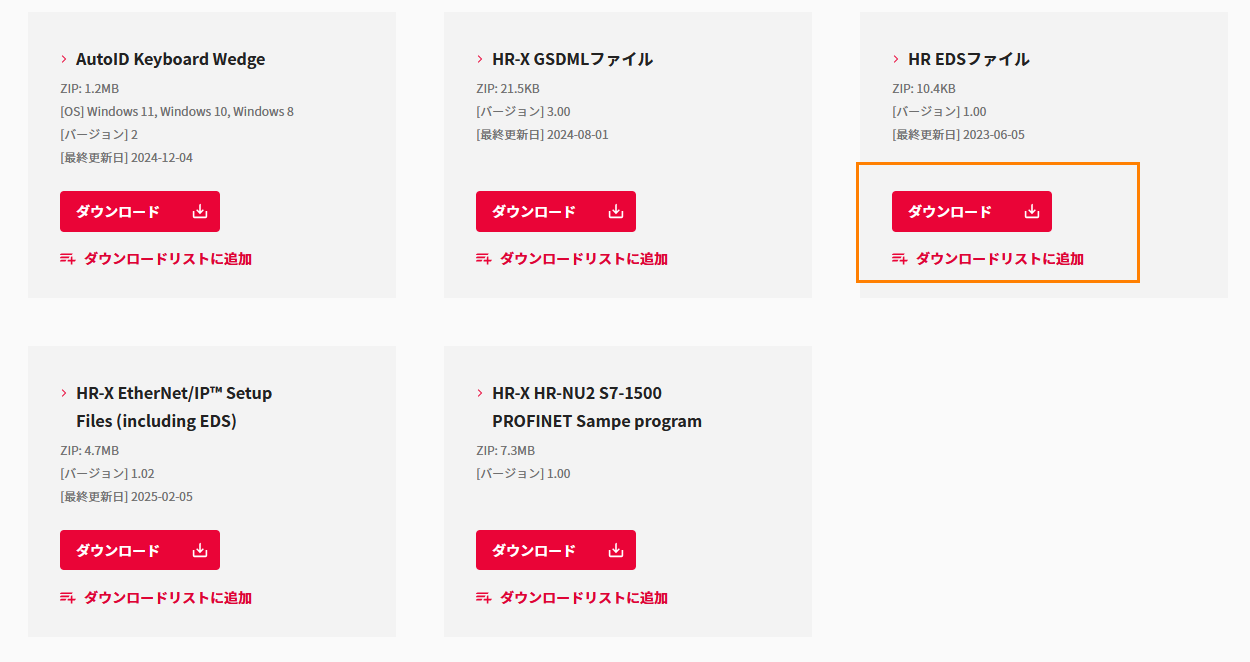
Download the HR-L2 EDS File from KEYENCE’s website.
Install EDS File
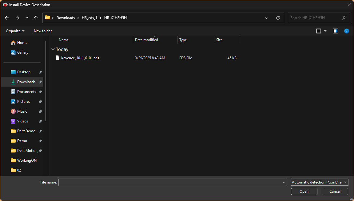
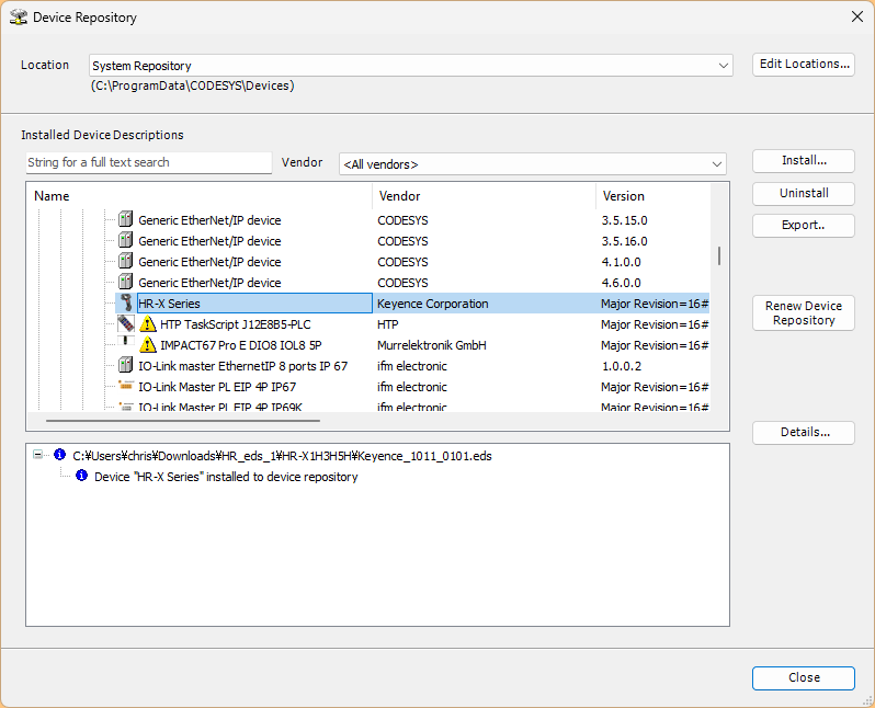
Let’s install the EDS file you just downloaded.
Done!
Configure Ethernet/IP Network
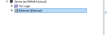
Add the Ethernet Driver.
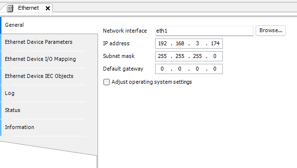
Open the General Tab and click the Browse button to select the appropriate network interface for the Codesys hardware.
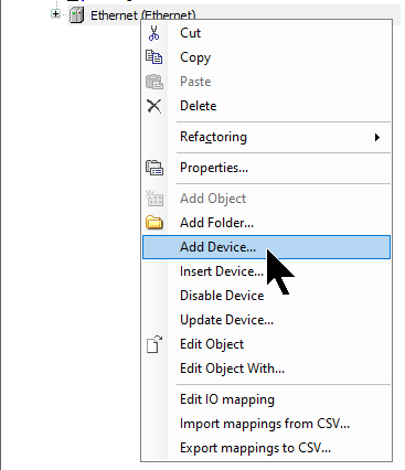
Add Ethernet/IP Scanner
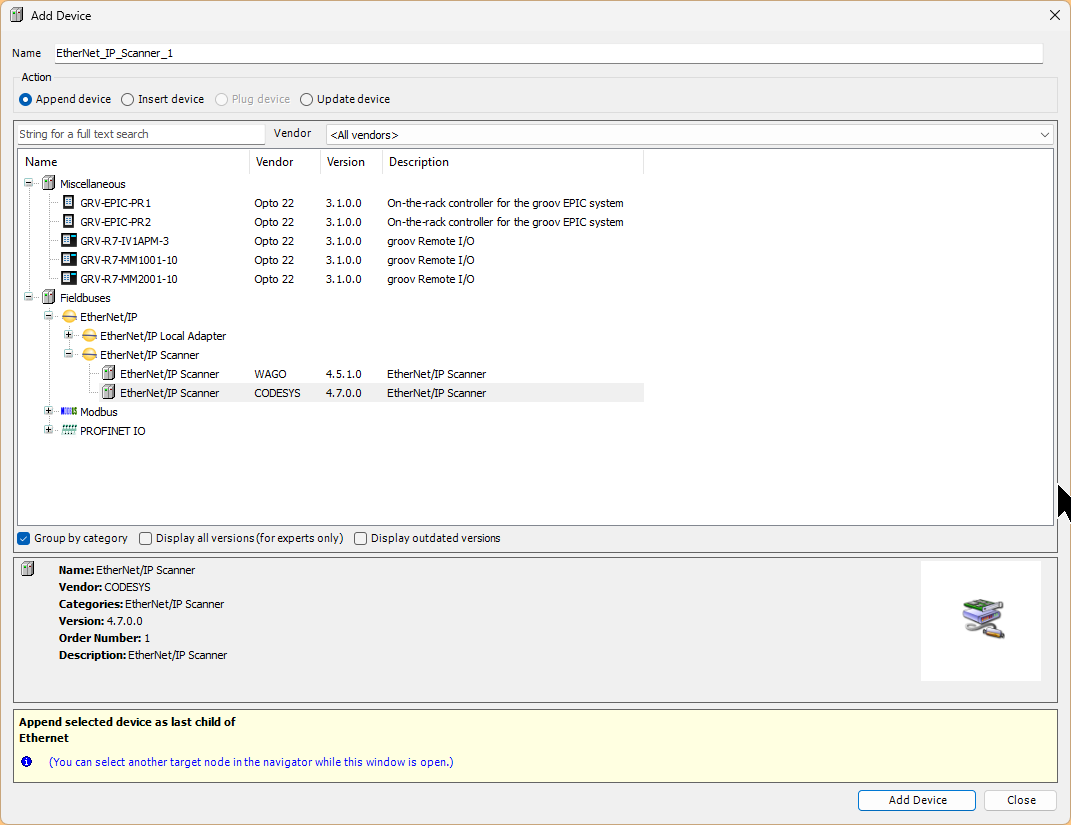
Next, to add the Ethernet Scanner, right-click the Ethernet Driver and select > Add Device.
Select Fieldbus > Ethernet/IP Scanner > Ethernet/IP Scanner, and click Add Device to add it.
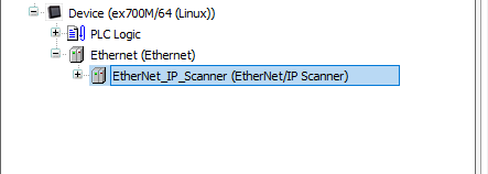
Done!
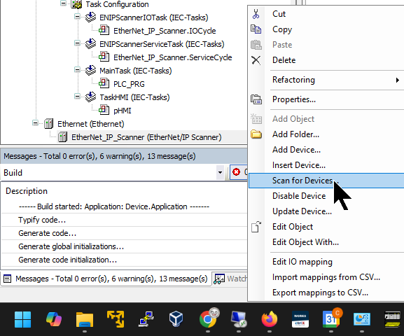
Scan for Devices
There are two ways to add an EtherNet/IP Adapter: auto-scan and manual addition. First, we explain the auto-scan method. Right-click EtherNet/IP Scanner and select > Scan for devices.
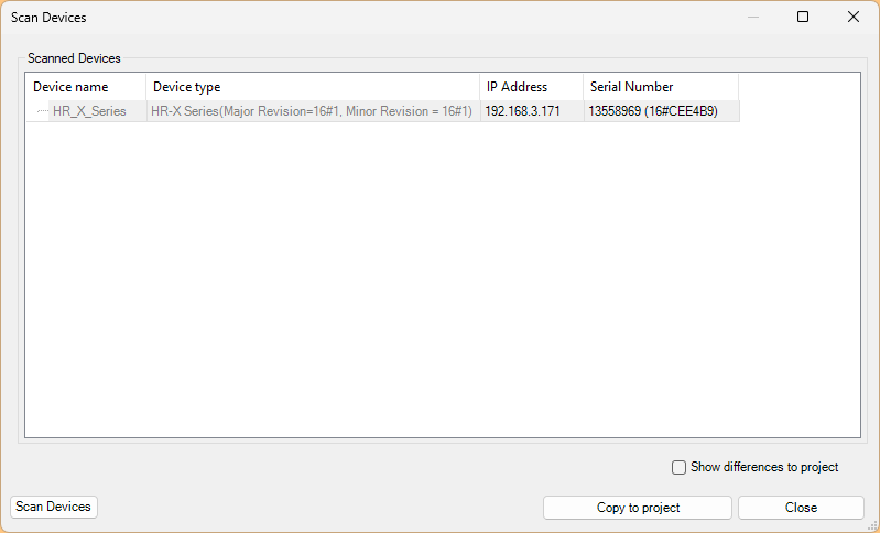
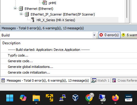
Done! If the HR-X100WB is already connected, the corresponding device will appear in the search results. Click “Copy to project” to add the device to your hardware configuration.
Done!
Manual Add Devices
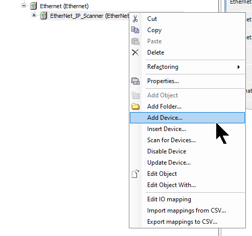
Next, we explain how to manually add an EtherNet/IP Adapter. Right-click EtherNet/IP Scanner > Add Device.
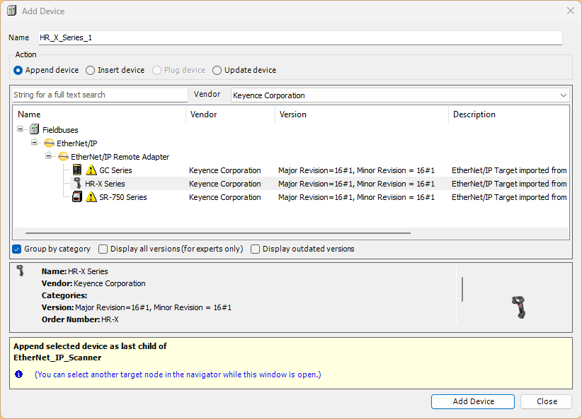
Select EtherNet/IP > EtherNet/IP Remote Adapter > HR-X Series, and click > Add Device to add it.
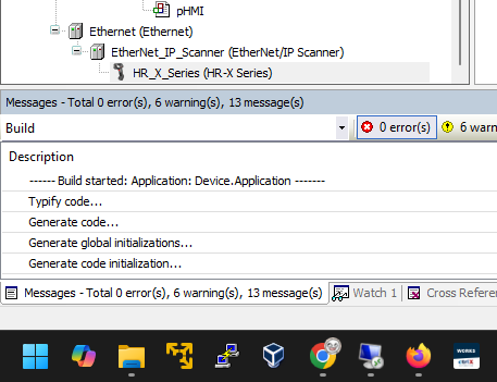
Done!
Configure HR-X100WB
Next, configure the KEYENCE HR-X100WB.
IP Address
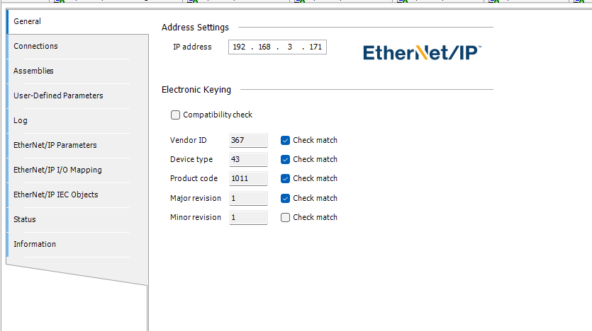
First, open the General Tab and set the IP address of the KEYENCE HR-X100WB.
Connection
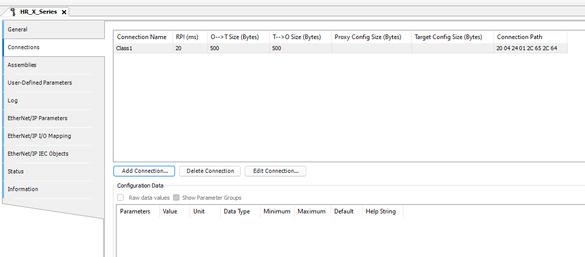
Next, open the Connections screen to configure the EtherNet/IP connection between Codesys and the HR-X100WB. In this article, we set it to a Class 1 connection.
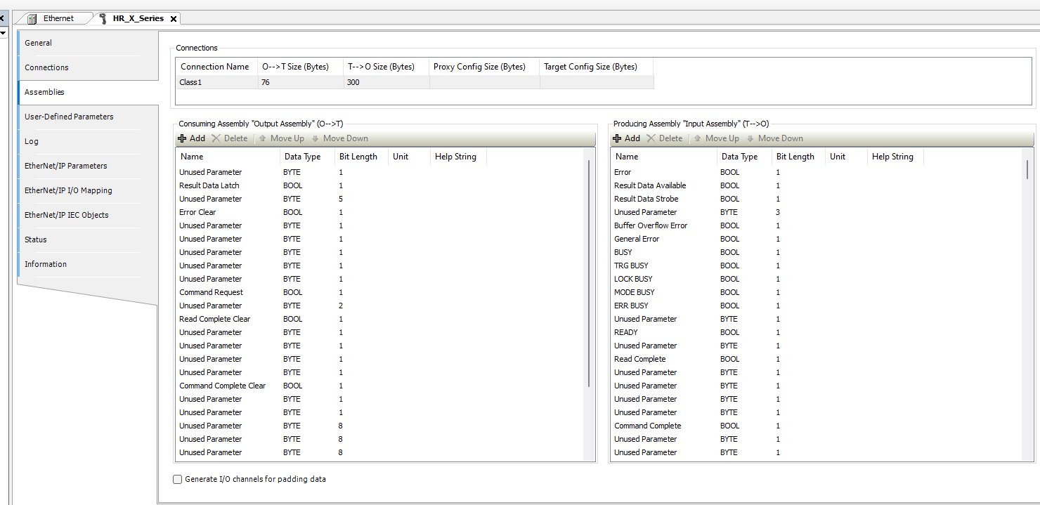
Open the Assemblies Tab to define variables for EtherNet/IP communication with KEYENCE’s HR-X100WB.
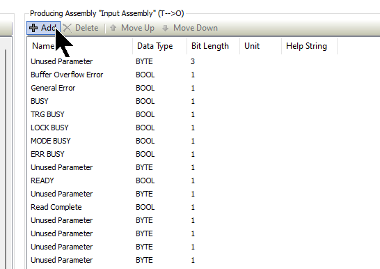
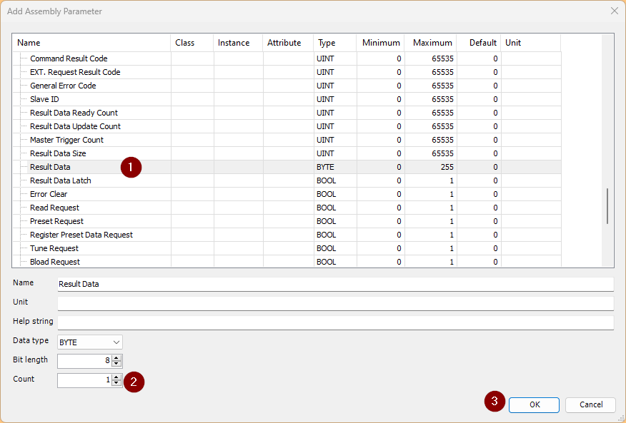
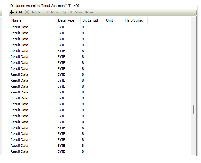
By default, there is only 1 byte for the variable read from the barcode reader, so click +Add to increase the variable size.
The Add Assembly Parameter screen appears. Select Result data and set the Count for additional consecutive bytes. Finally, click OK to confirm the settings.
Done!
Program
Now we create the program.
DUT stKeyenceHRX100WBIn
This is a structure created to match the status parameters of KEYENCE’s HR-X100WB.
TYPE stKeyenceHRX100WBIn :
|
|---|
fbKeyenceHRX100WB
This program parses data read from KEYENCE’s HR-X100WB into structure variables and transfers the read string in bulk.
FUNCTION_BLOCK fbKeyenceHRX100WB
|
|---|
IF iReadDataReadyCountBackup <> iostKeynceHRX100WB.in.iReadDataReadyCount THEN
|
|---|
POU
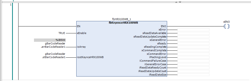
Finally, call the FB in the MAIN program.
Mapping
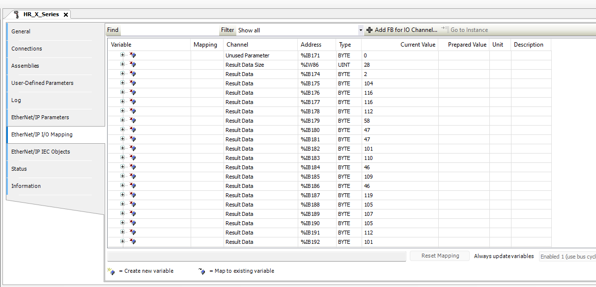
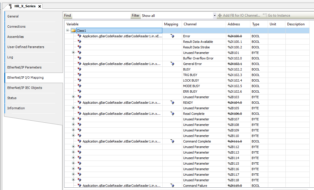
Map the variables along with the structure in EtherNet/IP I/O Mapping.
Download
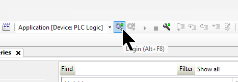
Download the project to the Codesys Runtime.
Result
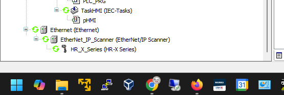
Done! EIP communication between Codesys Runtime and HR-X100WB is established.
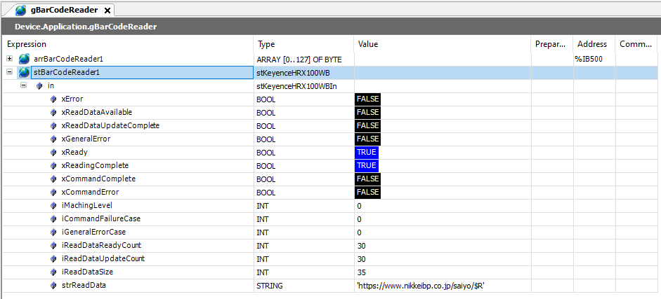
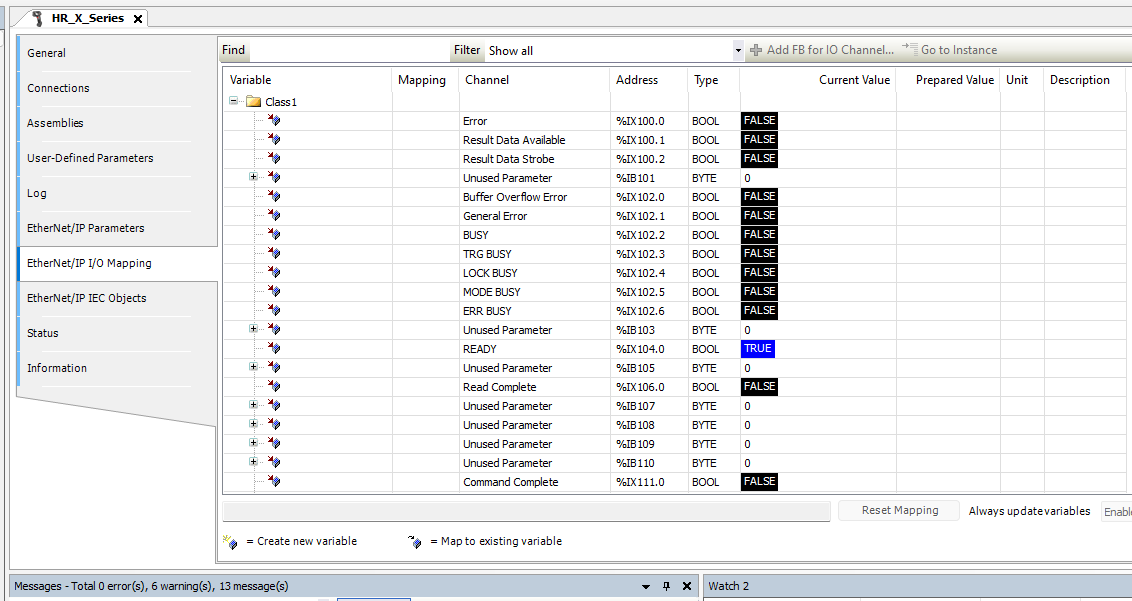
The READY signal was successfully received from HR-X100WB.
The result when KEYENCE’s HR-X100WB scanned a QR code was also verified.