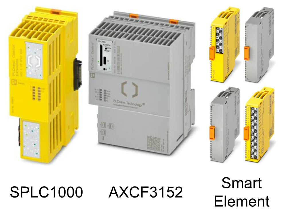
This is the second episode of using Phoenxic Contact PLCNEXT and Safety ControllerSPLC1000. This time, we will build Safety inputs and outputs for SPLC1000, AXCF3152, and Smart Element, and communicate with Profisafe.
Let’s start!
Reference Link
Thanks!
The EPC1522 Edge PC used in this article was loaned by Phoenix Contact Japan. Thank you very much.
Founded in Germany in 1923, Phoenix Contact is a global company with 20,300 employees in 55 locations worldwide.
With the concept of “All Electric Society”, the company aims to provide comprehensive solutions for the realization of electrification, networking, and automation in all industrial sectors. Phoenix Contact’s products are used in a variety of applications such as industrial production facilities, infrastructure, energy, and electronics connections.
Phoenix Contact Japan was established in Yokohama in December 1987 as the first local subsidiary in Asia, and currently operates through 10 sales offices in Japan.
Click here to visit their website.
https://www.phoenixcontact.com/ja-jp/

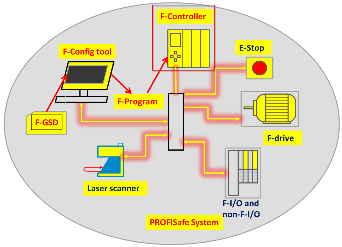
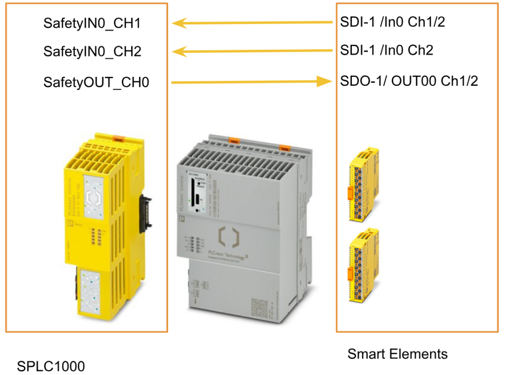
SPLC1000 with PROFisafe
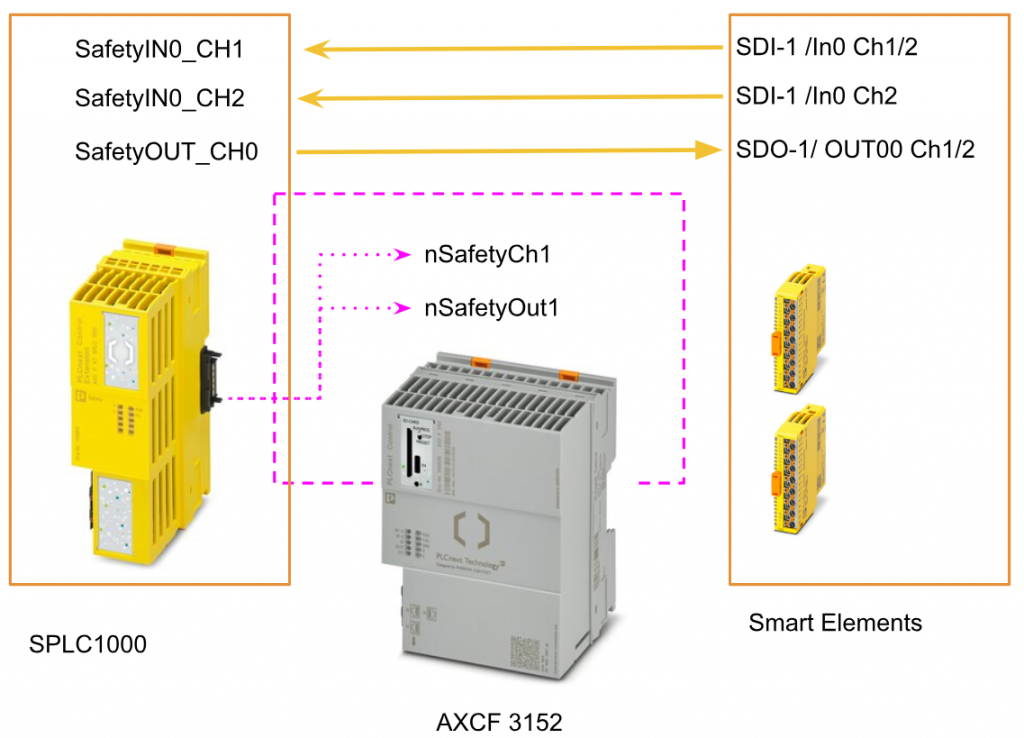
Here is a schematic of the PROFISafe system.

As the F-Host in PROFIsafe
The SPLC 1000 is a powerful 2-channel safety-related controller for PROFIsafe: The PROFIsafe protocol is transmitted via the PLCnext Control device and the PROFINET network. The safety functions are programmed in the PLCnext Engineer software and the SPLC 1000 monitors and controls the safety functions of the PROFIsafe system.
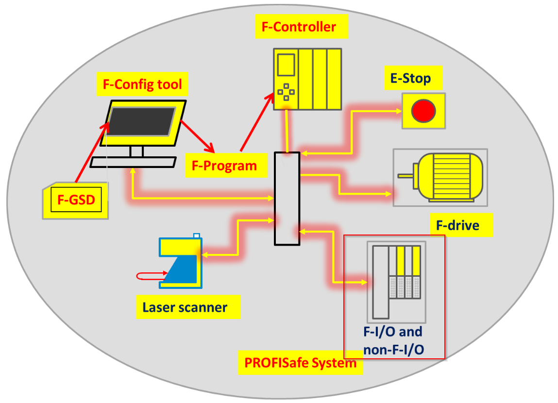
As the F-Device in PROFIsafe
SPLC 1000 can be operated as an F-Device on a Safety Controller such as RFC 4072S/Siemens FCPU.
In the event of an error / Safe state (Failure State)
The integrated diagnostics of the SPLC1000 can detect all serious errors, errors that lead to the loss of the programmed safety function or errors that occur that could have various or adverse effects. When this happens, the device switches to the failure state (Failure State) and the F device safety outputs are set to zero (FALSE).
The safety state is also indicated by the FS (Failure State) LED lighting up red.
If an error occurs, information about the error can also be checked from PLCnext Engineer by connecting PLCnext Engineer and the CPU.
Passivation and reintegration
If the communication between the SPLC 1000 and the F-Device is interrupted due to a communication error, the F-Device is “passivated”. The passivation state is a mechanism to prevent the F-Device from waking up from an interrupted communication state.
The passivation state of the F-device is handled by the PLCnext Engineer as a Bool variable.
It can also be generated automatically for each F-Device by PLCnext Engineer and passivated or reintegrated from the application program using these variables.
If there is an Operator acknowledge request for an F-Device in the Passivation state, a PROFIsafe-specific acknowledgement is used. It is also possible to use non-safety related signals
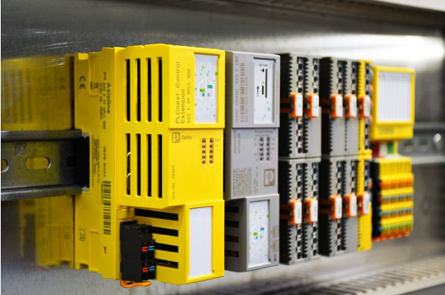
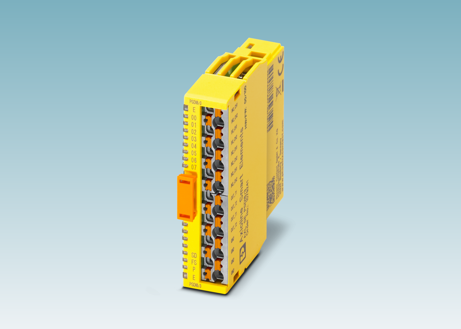
Smart Element
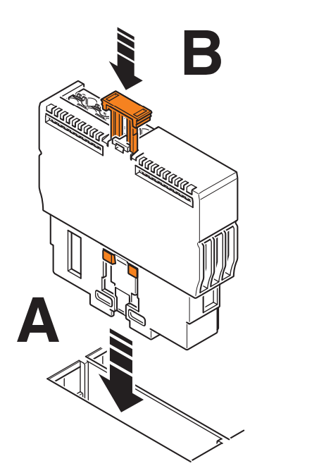
Installation
The Smart Element and its slots are mechanically designed to allow insertion in only one direction. Here are the steps to Install.
- Insert the Smart Element vertically into slot (A).
- Push the release mechanism all the way to the back of the guide (B).
Remove
Here is the procedure to Uninstall.
- Disconnect any inserted cables before removing the Smart Element.
- To remove the Smart Element from the slot, pull the release mechanism vertically upward (A).
- Pull the Smart Element out of slot (B).

AXL SE PSDO4/2 2A
The AXL SE PSDO4/2 2 A Smart Element is designed for use with PROFIsafe systems, and the Smart Element is integrated into the Axioline F system via the Axioline F backplane.
The AXL SE PSDO4/2 2 A is designed for connection of 1- or 2-channel actuators. In addition, the following safety features can be implemented.
- Safety output
- Safe transmission of I/O signals
AXL SE PSDO4/2 2 A can be used to achieve the following safety integrity.
- Up to SIL 3 in accordance with IEC 61508
- Up to SILCL 3 according to EN 62061
- 4/PL e in accordance with max. Cat. EN ISO 13849-1

Structure
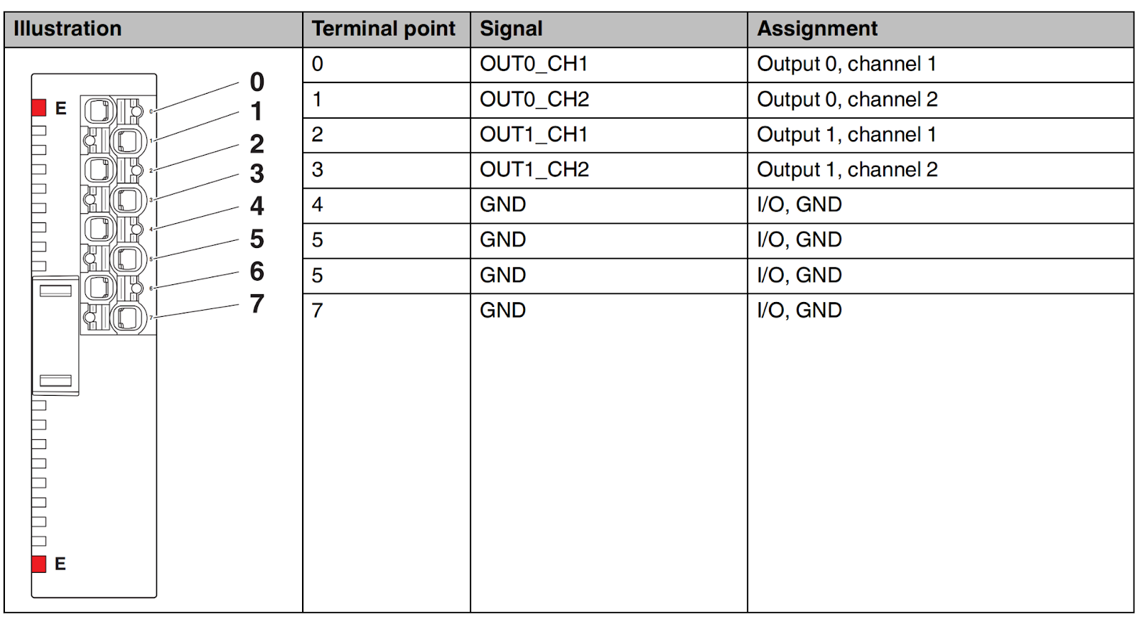
Terminal
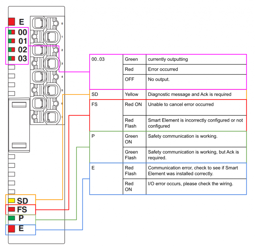
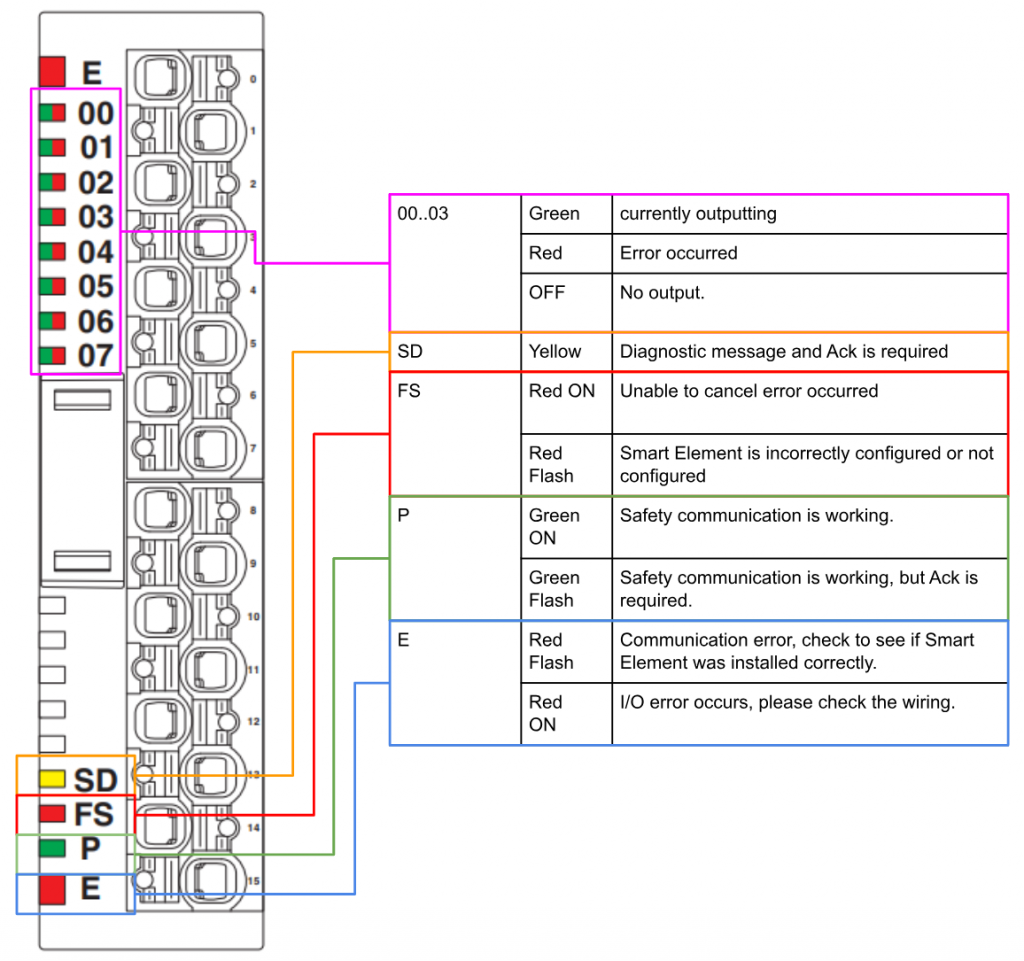
LED
Please refer to the Manual for details.
Process data words
Here is the Process Data for AXL SE PSDO4/2 2A.

In fact, once Smart Elements is added to the project, the data is automatically generated.

AXL SE PSDI8/3
The AXL SE PSDI8/3 Smart Element is designed for use with PROFIsafe systems, and the Smart Element is integrated into the Axioline F system via the Axioline F backplane.
The AXL SE PSDI8/3 is designed for connection of 1- or 2-channel sensors. In addition, the following safety features can be implemented
- Safety Inputs
- Safety transmission of I/O signals
AXL SE PSDO4/2 2 A can be used to achieve the following safety integrity
- Up to SIL 3 according to IEC 61508
- Up to SILCL 3 according to EN 62061
- Up to Cat. 4/PL e according to EN ISO 13849-1
Structure
Terminal

LED
Please refer to the Manual for details.
Process data words
Here is the Process Data for AXL SE PSDI8/3.
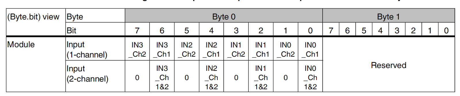
Internal bus
The internal bus in the Axioline F station is configured left-aligned and the internal runtime Cycle time of the SPLC 1000 for the internal bus value corresponds to 1 Cycle of the SPLC 1000 (TZSPLC).
The SPLC 1000 cycle time can be set by the PLCnext Engineer from 5 ms to 15 ms. (Default TZSPLC = 5 ms).

Implemenation
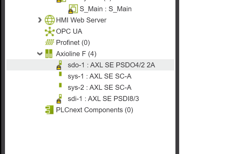
In this case, we will build Safety inputs and outputs for the SPLC1000/AXCF3152 and Smart Element to communicate Profisafe in this tutorial. 32 F-Devices can be connected to the SPLC1000 at maximum.
Configuration
The total maximum address space available for IO variables in PLCNEXT is as follows
- The total standard input data (NSI, input exchange area) is a maximum of 128 bytes (data direction “I”: SPLC 1000 standard controller).
- The total standard output data (NSQ, output exchange area) is 128 bytes (data direction “Q”: SPLC 1000 standard controller) maximum.
Module1
Configure the AXL SE PSDO4/2 Set 2A safety output.
The Safety Parameters setting screen appears.

F_Source_Address
F_Source_Address is a parameter set to identify the F-Host (Profisafe Controller). Its F_Source_Address is assigned to the Safety Controller and is used for all communication relationships assigned to this Safety Controller. The value of F_Source_Address must be between 0dec and 65534dec and must match across the network.
In PLCNEXT Engineering, F_Source_Address Default is 1024, so keep it at the Default value if not needed.

F_Dest_Add
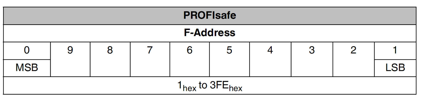
In PROFIsafe, an F-Device is identified by an F-Address.
The F-Address must be uniquely assigned to each safety device.
F_Dest_Add (F_Destination_Address) is used to uniquely identify a safety device.
This address is defined on the F-Device via a DIP switch and is checked immediately after it is entered into the PLCnext Engineer software. PLCnext Engineer checks that the entered address is unique within the configured network and that the range is correct.
Valid setting range: 0dec to 65534dec, cannot overlap with other devices.
In this article, this Module is set to F_Dest_Add=1.

Assignment can be configured in detail, such as setting whether the output is one-to-one or one-to-two. For this article, we will set Used.1-channel both.

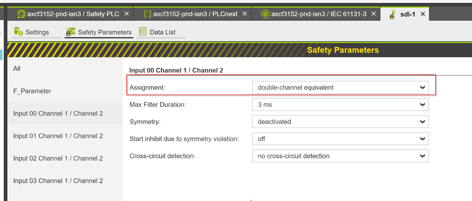
Module4
Set F_Dest_Add to 3.

Now we can configure the Input00 Sets input parameters for Channel 1/Channel 2.By setting Assignment to “Double-channel equivalent”, Input0 becomes a 1:2 input setting
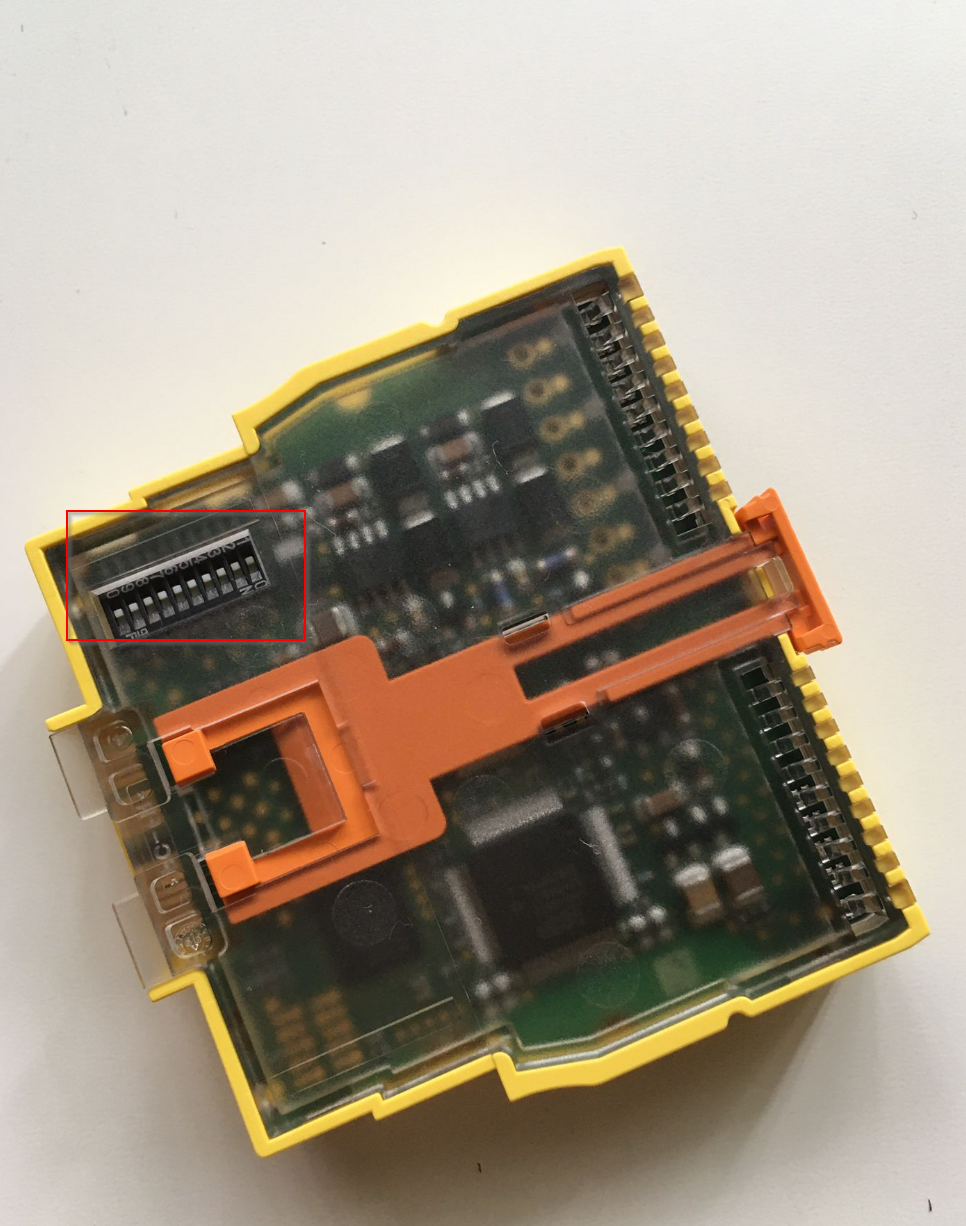
DIP Switch
I set F_Dest_Add from F_Parameters, but the Smart Element DIP switches must also match that setting (some devices, like the Siemens ET200SP, allow Assign Safety Address to be set directly from the engineering tool).

The F-Address setting range is 1-3FE.
This is the actual location of the Safety Smart Elements DIP switch.
Safety PLC Variables
The SPLC 1000 supports monitoring and control of the device’s internal F-Host communication relationships and can be configured with the necessary monitoring and control data from the PLCnext Engineer software.
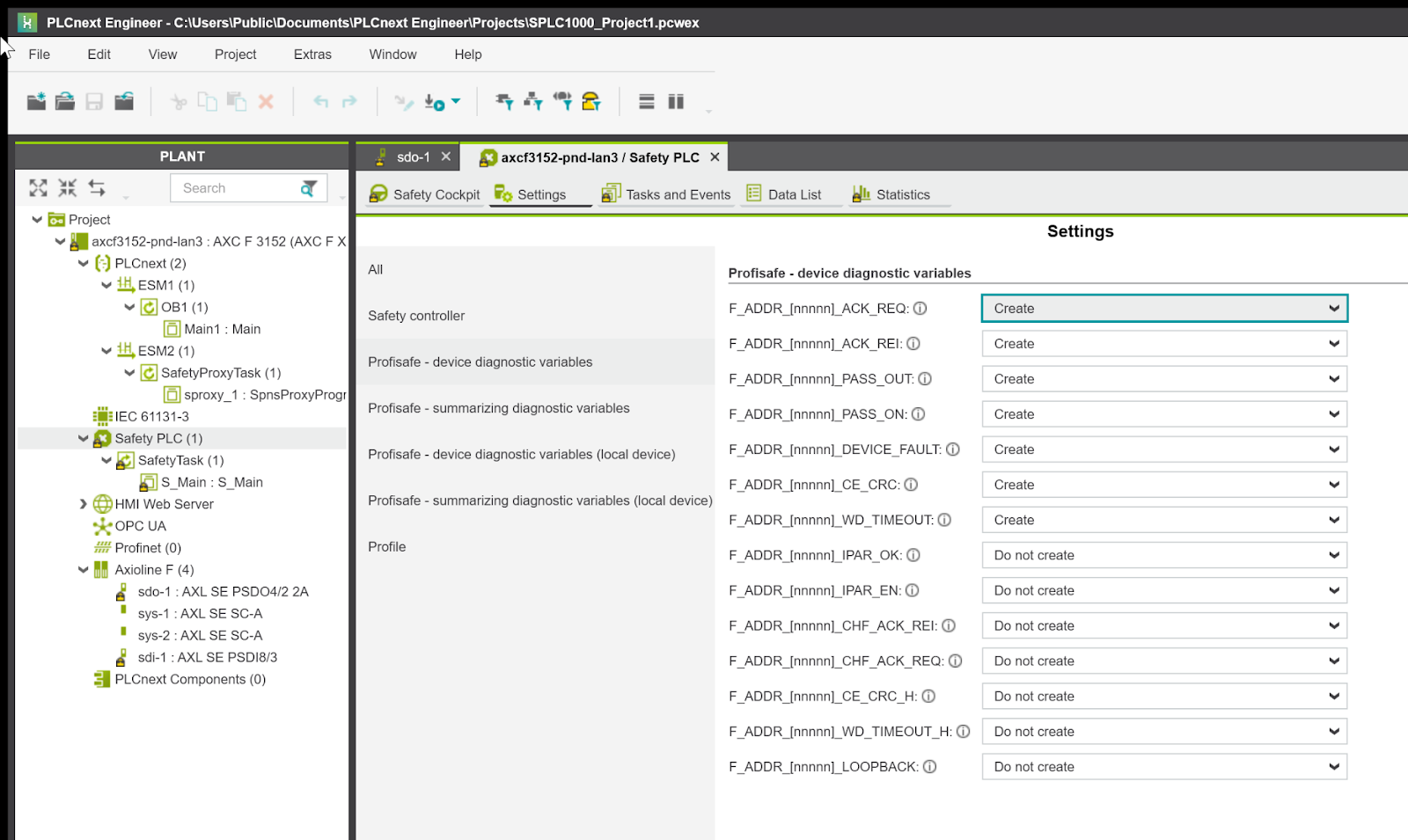
In PLCnext Engineer Default, seven non-safety related management/diagnostic variables can be created for each F-Device in the safety-related controller data list. If required by the application, they can be enabled/disabled via Create/Do not create from PLCnext Engineer.
PLCnext Engineer でこれらの変数を標準コントローラの安全関連以外の交換変数にリンク
With PLCnext Engineer these variables can be linked to non-safety-related exchange variables of standard controllers. So, the user needs to define the non-safety-related interchange variables in software. Don’t worry, we will explain the procedure and the Safety PLC Variables used in this article.
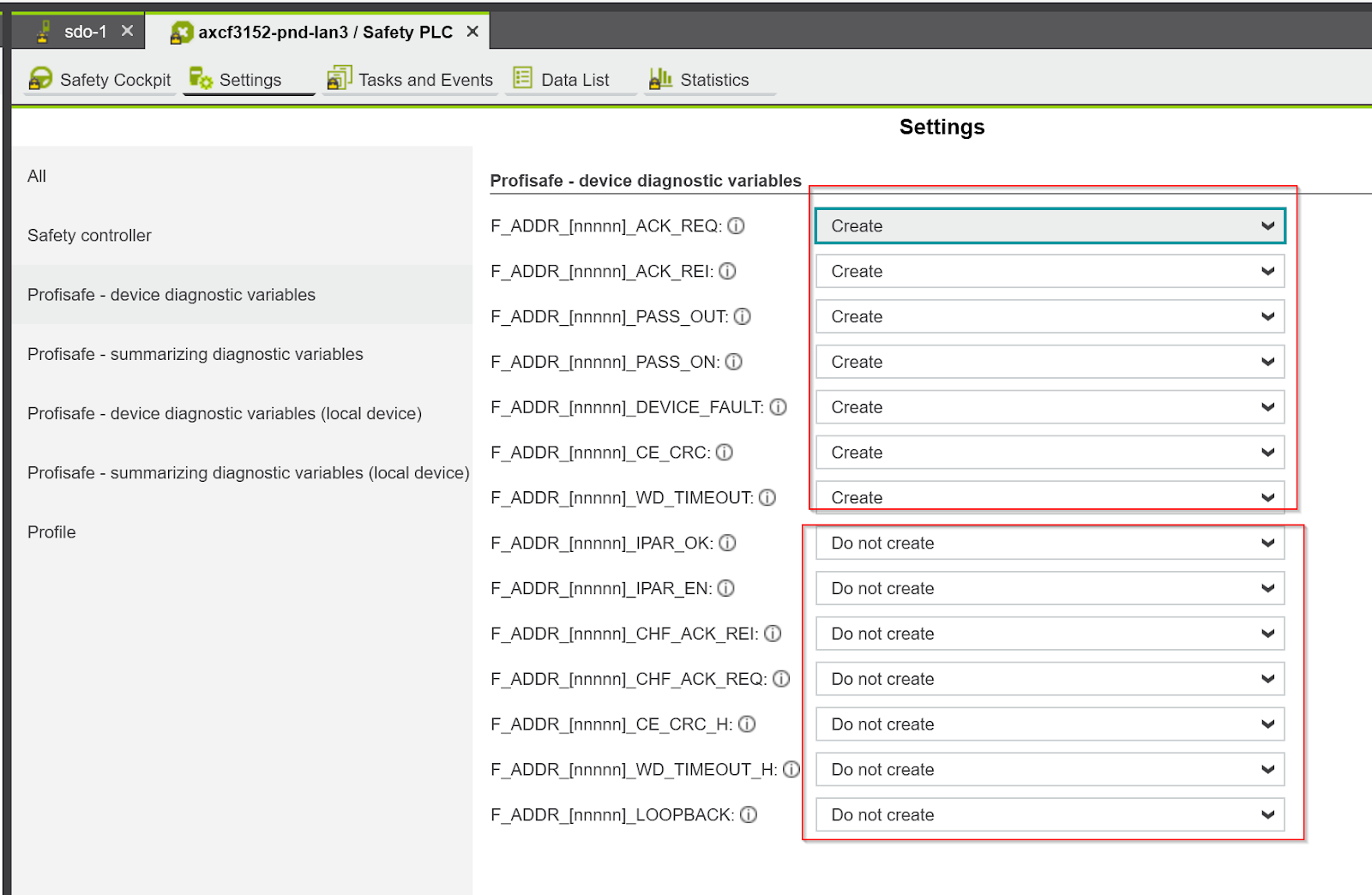
The F_ADDR_XXXX_XXXX variable was created as shown below.
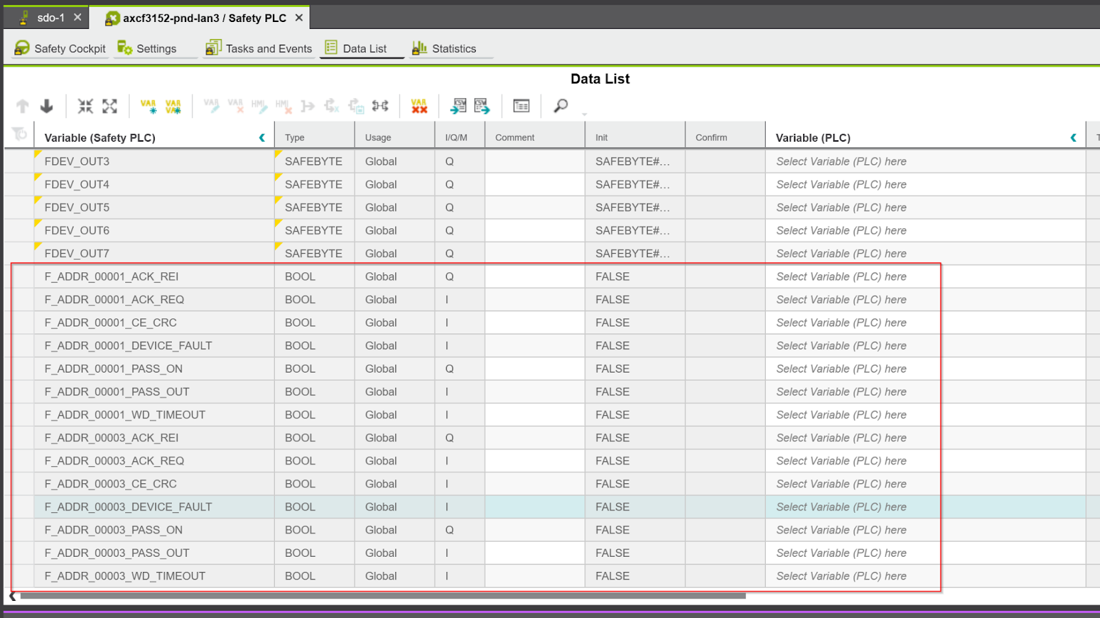
F_ADDR_XXXXX_
PLC Engineering generates variable Mapping for each F-Devices with rules such as F_ADDR_XXXX_VariablesName. For example, if F-Devices is F_Dest_Add=1, the variable name for F-Devices1 is F_ADDR_0001_XXXX. This rule is the same as for Siemens Safety PLC.
F_ADDR_XXXXX_ACK
F_ADDR_XXXXX_ACK_REI :BOOL
If F-Device XXXXX requires an acknowledgement request by the operator (F_ADDR_XXXX_ACK_REQ=True), it is Ok if the variable F_ADDR_XXXX_ACK_REI is changed from False>True.
F_ADDR_XXXXX_ACK_REQ :BOOL
F-Device XXXXX is a signal requesting operator confirmation after clearing an error.
True=Requesting operator confirmation.
Reason for F_ADDR_XXXXX_ACK_REQ=True:
- Communication error (CRC, F_WD_TIME_OUT)
- F Device Error
F_ADDR_XXXXX_PASS
F_ADDR_XXXXX_PASS_ON :BOOL
True=puts the corresponding F-Devices into the passive state.
Note that resetting this variable to FALSE will cause safe input/output data to be sent immediately; be careful not to put the system/machine in an unsafe state when resetting the passive state of an F-Device.
F_ADDR_XXXXX_PASS_OUT * :BOOL
True=F-Device XXXXX is passivated.
Reason for passivation:
- Program passivation system variable by F_ADDR_XXXXXX_PASS_ON
- Communication Errors
- Device Error
- Parameter setting error
F_ADDR_XXXXX_DEVICE_FAULT : BOOL
F Indicates the error status of the device. If this variable is set to TRUE, you must first remove the cause of the error and perform an acknowledgment. To perform an acknowledgment, set the following devices to TRUE
- F_ADDR_XXXXX_ACK_REI
- ACK_REI_GLOBAL
If the cause of the error is removed, the F_ADDR_XXXXX_DEVICE FAULT variable will again be FALSE.
F_ADDR_XXXXX_CE_CRC :BOOL
Indicates the Communication error (F_CE_CRC) status of the F device.
This parameter is True if at least one of the following reasons applies
- Mismatch in parameter settings between F-Host and F-Device
- Communication error between F-Host and F-Device
For example, when an F-Device detects a communication error caused by an incorrect CRC checksum during operation, it must first remove the cause of the error and then perform an acknowledgment.
Please set the following devices to True to get an acknowledgment:
- F_ADDR_XXXXX_ACK_REI
- ACK_REI_GLOBAL
If the cause of the error is removed, the F_ADDR_XXXXX_CE_CRC variable will again be FALSE.
F_ADDR_XXXXX_WD_TIME_OUT : BOOL
Indicates the Communication error (F_WD_TIME_OUT) status of the F device.
This variable is set when a communication error is detected when the parameter F_WD_Time of the F device is exceeded. If this variable becomes TRUE during operation, the cause of the error must first be removed and an acknowledgment must be performed.
Please set the following devices to True to get an acknowledgment:
- F_ADDR_XXXXX_ACK_REI
- ACK_REI_GLOBAL
If the cause of the error is removed, the F_ADDR_XXXXX_WD_TIME_OUT variable will again be FALSE.
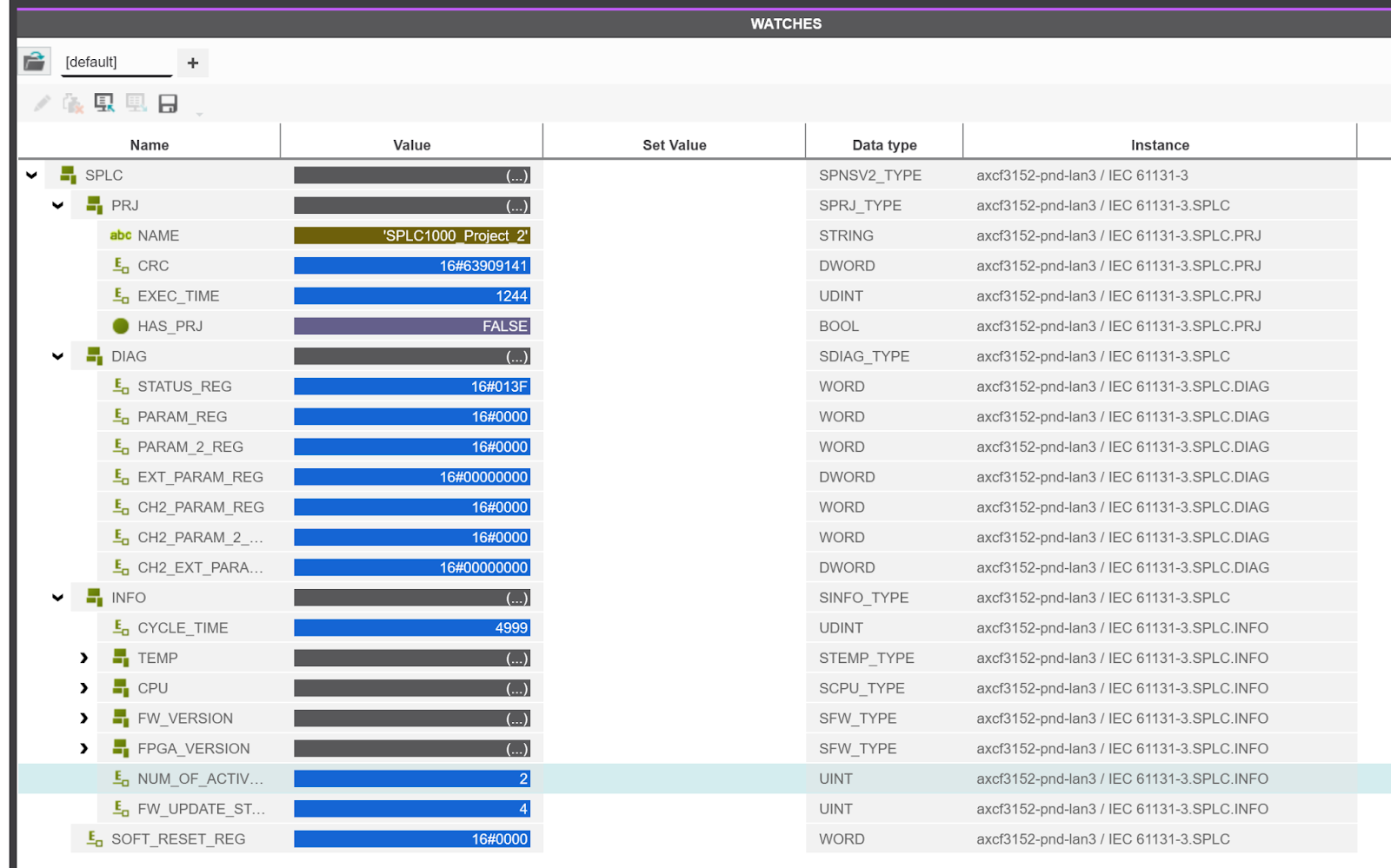
SPLC
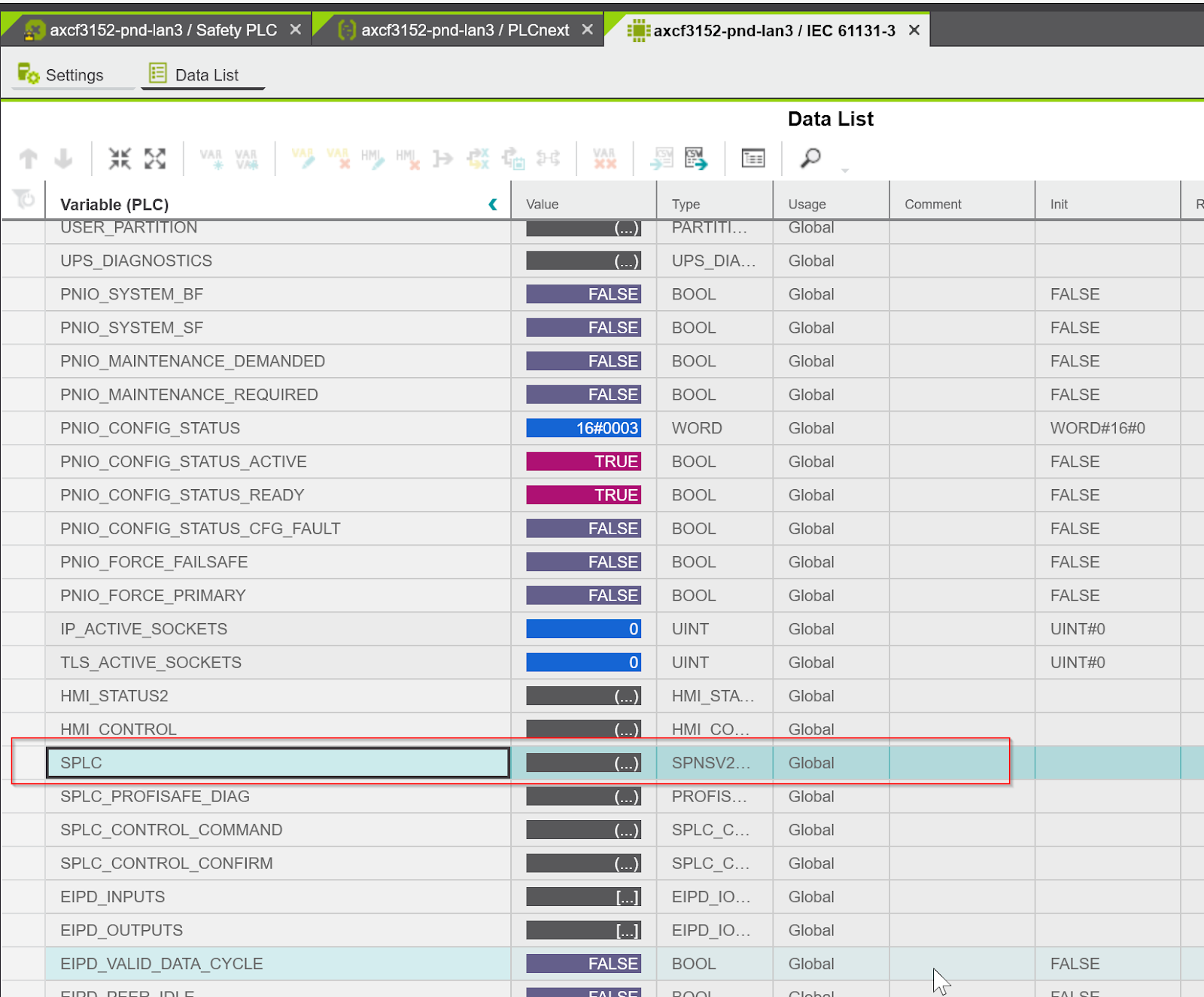
Besides Safety device variables such as F_ADDR_XXXX, the internal state of the SPLC1000 can be accessed from a structure variable called SPLC.
Open Safety PLC>SafetyTask(1)>S_Main.
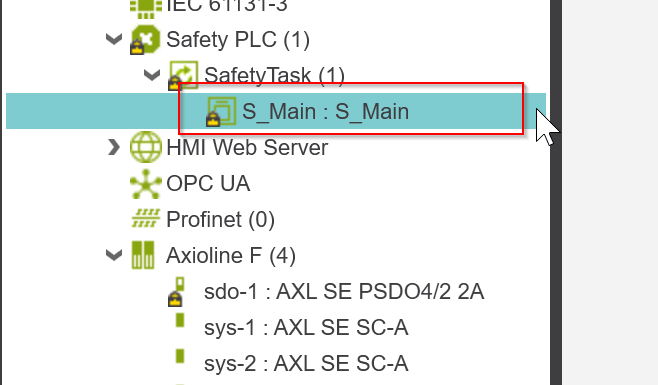
The Data List has a variable called SPLC.
Select SPLC>right click>Add to WATCHES.
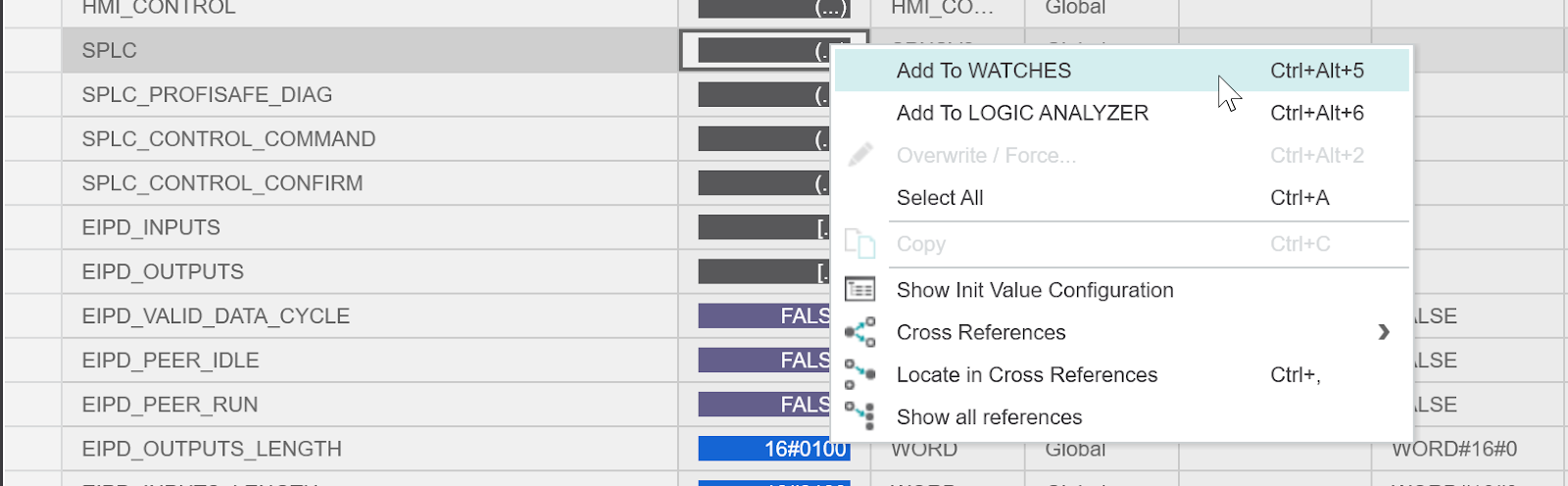
Select the top SPLC variable and confirm with >Ok.

Now you can check SPLC1000 and each LAN Port status, etc.
Mapping
The next step is Mapping between SPLC and AXCF 3152.
Smart Element <‐‐‐>SPLC1000
Initially, the Process I/O of each Safety Smart Element is mapped to the SPLC1000.
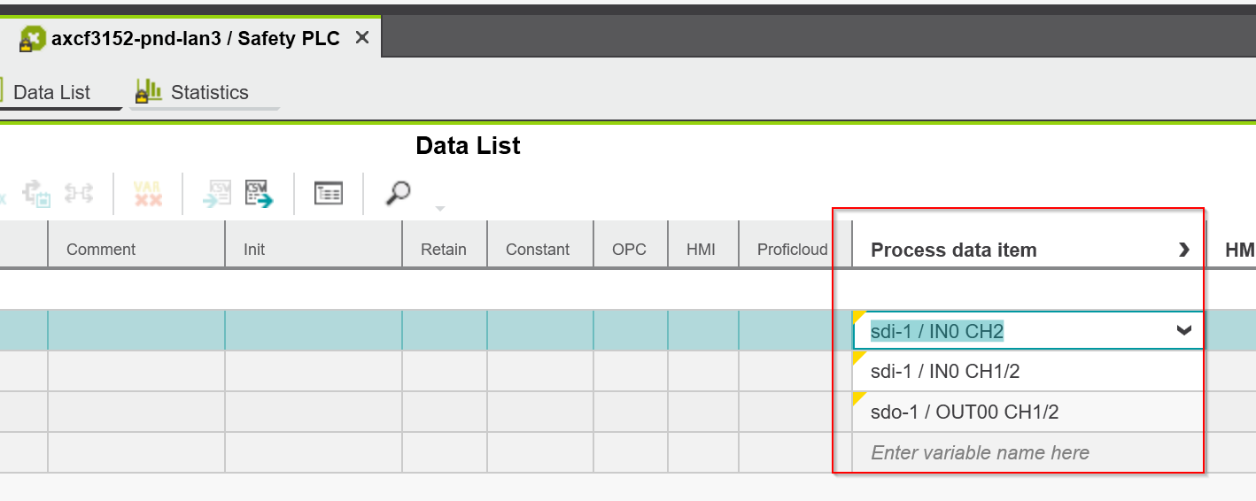
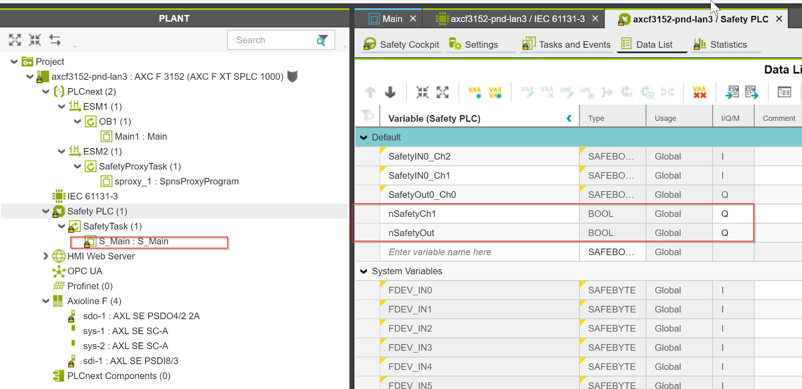
Open Safety PLC>Data List and define the safety input and safety output variables. Note that Type should be SAFEBOOL and set I and Q for the I/Q/M fields.
(I=INPUT,Q=OUTPUT)
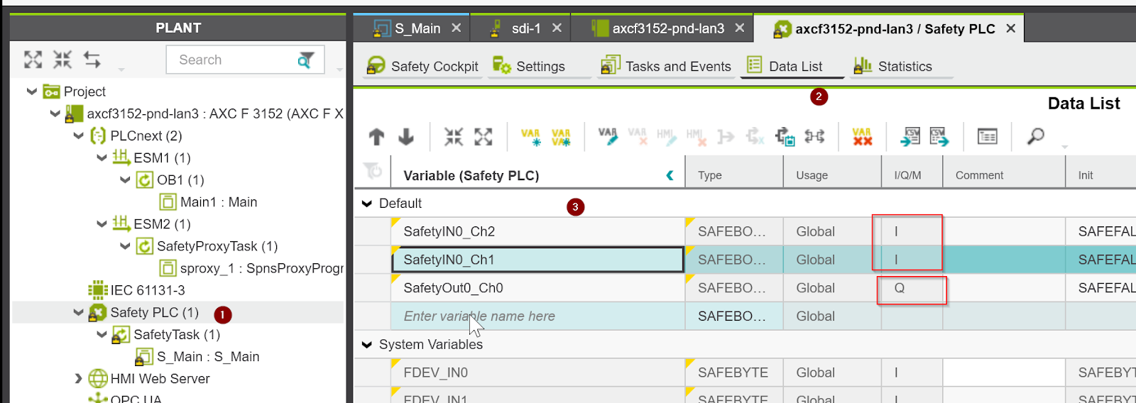
Set I to Process Data for safety input and O to Process Data for safety output.
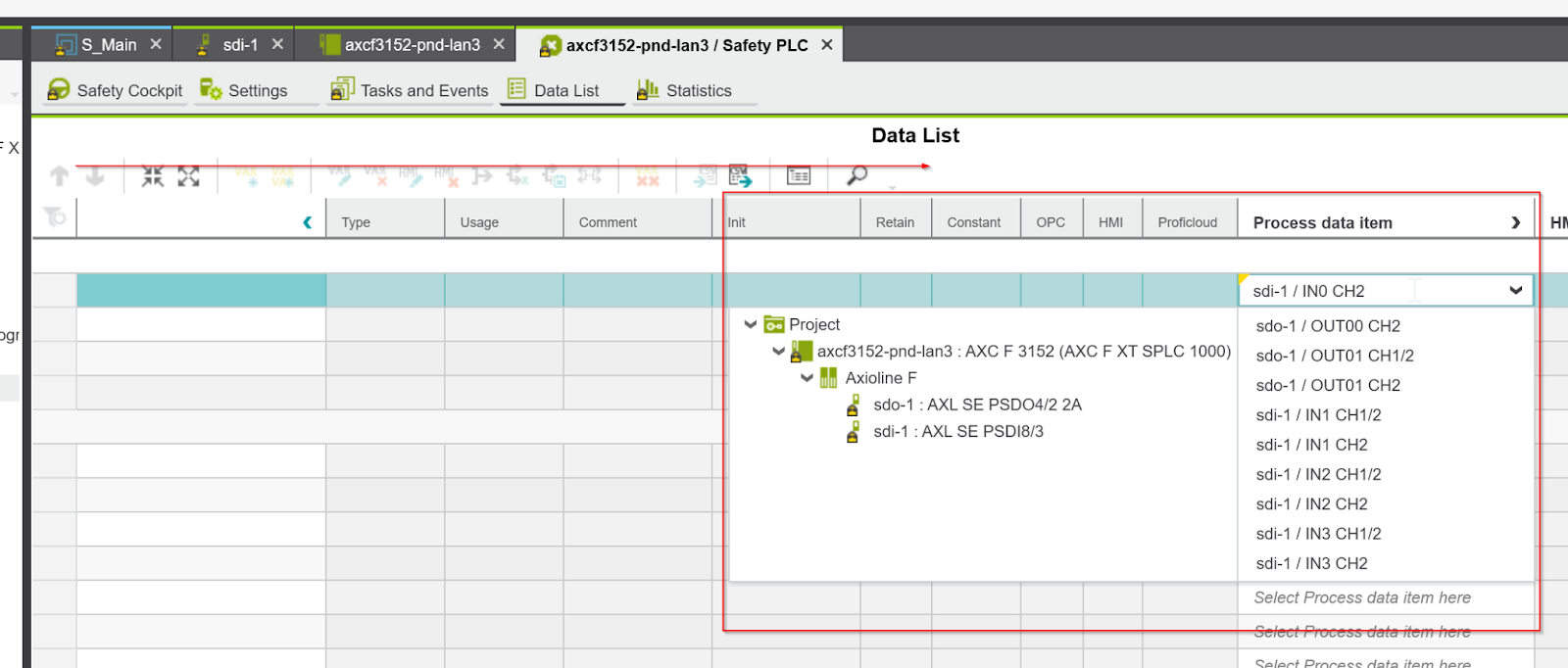
Done!
AXCF3152 <‐‐‐>SPLC1000
After mapping the variables between the SPLC1000 and the Smart Element, the next step is to link the data between the AXCF3152 and the SPLC1000.
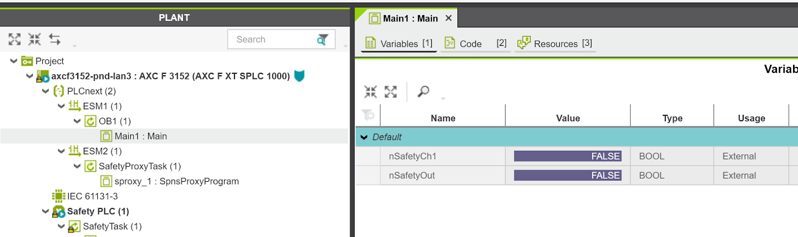
Open the AXCF3152 executable program and define two External variables from >Variables.
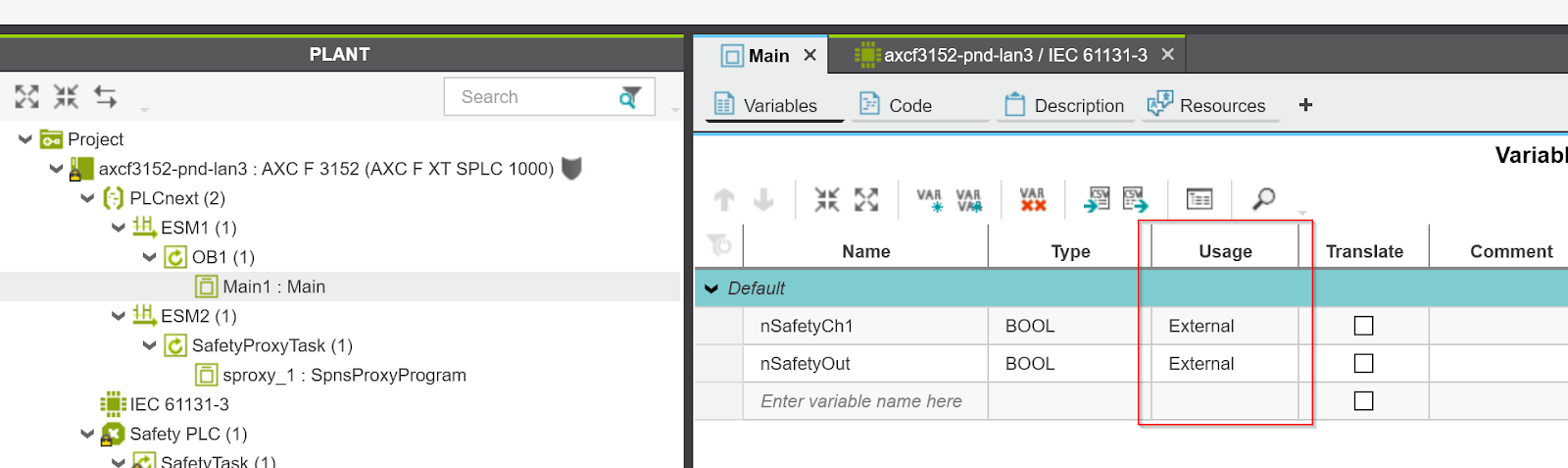
Click IEC61131-3 Field to display the variables you have just defined.
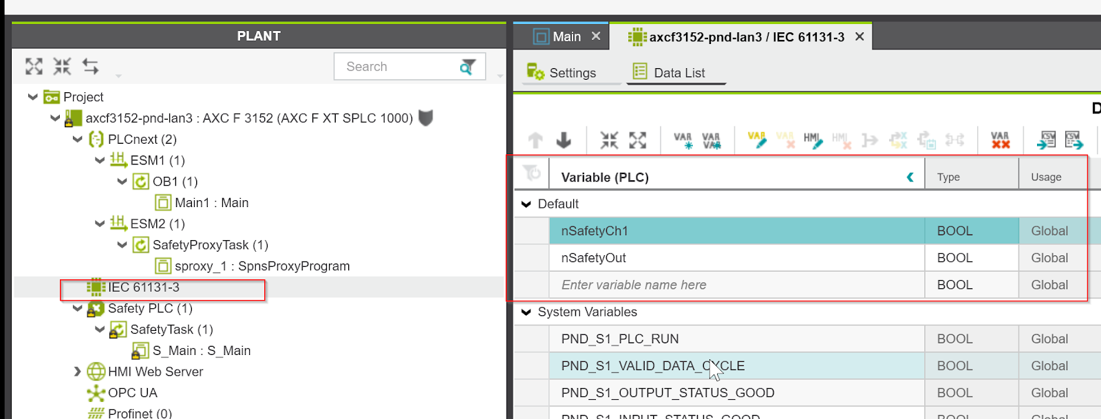
Right click on nSafetyCh1 nSafetyOut>Add Variable(Safety PLC) to add a safety variable.

Done!We now have a safety variable Mapping tied to AXCF3152.

After opening S_Main, nSafetyCh1 and nSafetyOut are also available.
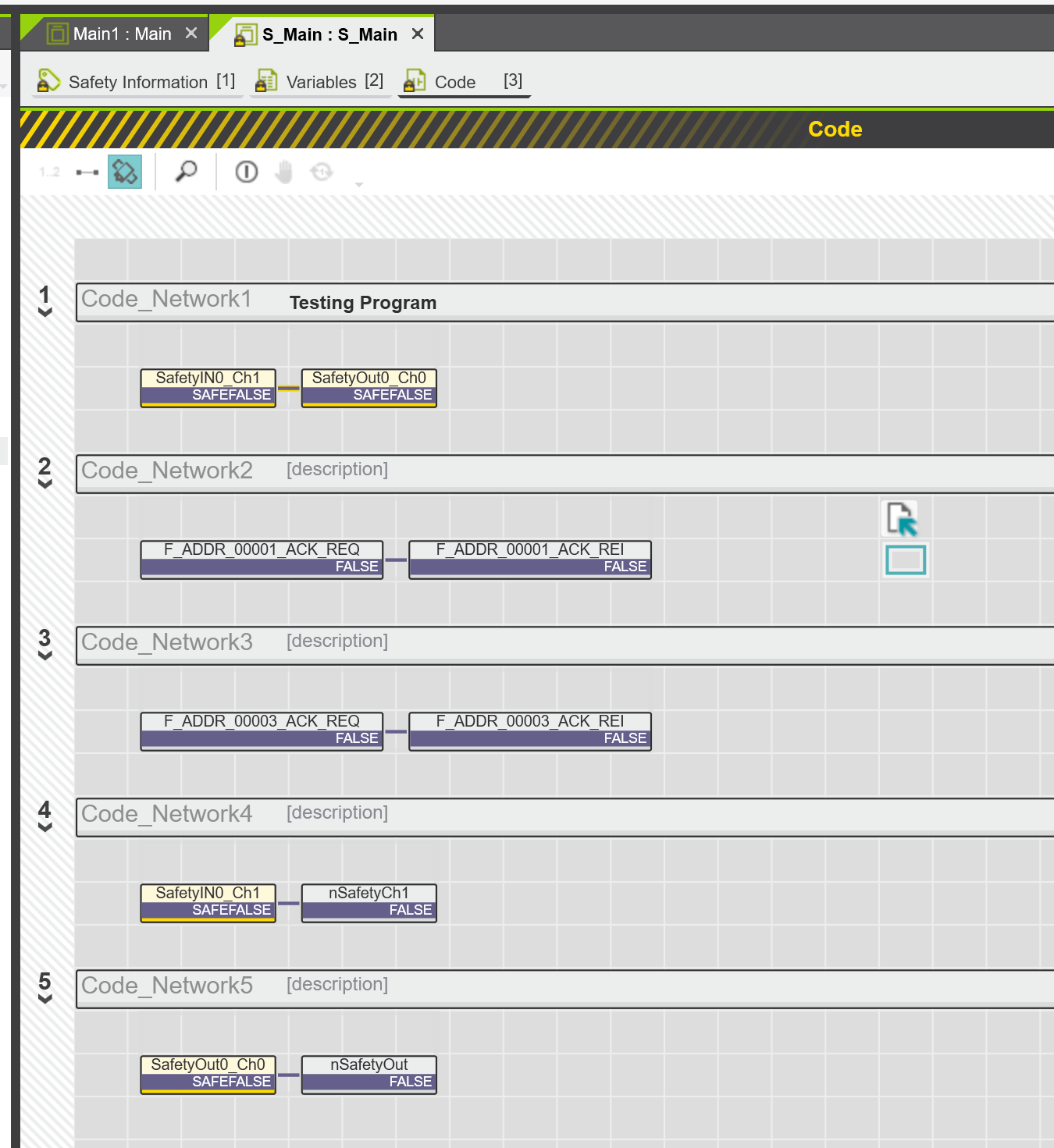
Program
The final step is to create a simple Safety program.
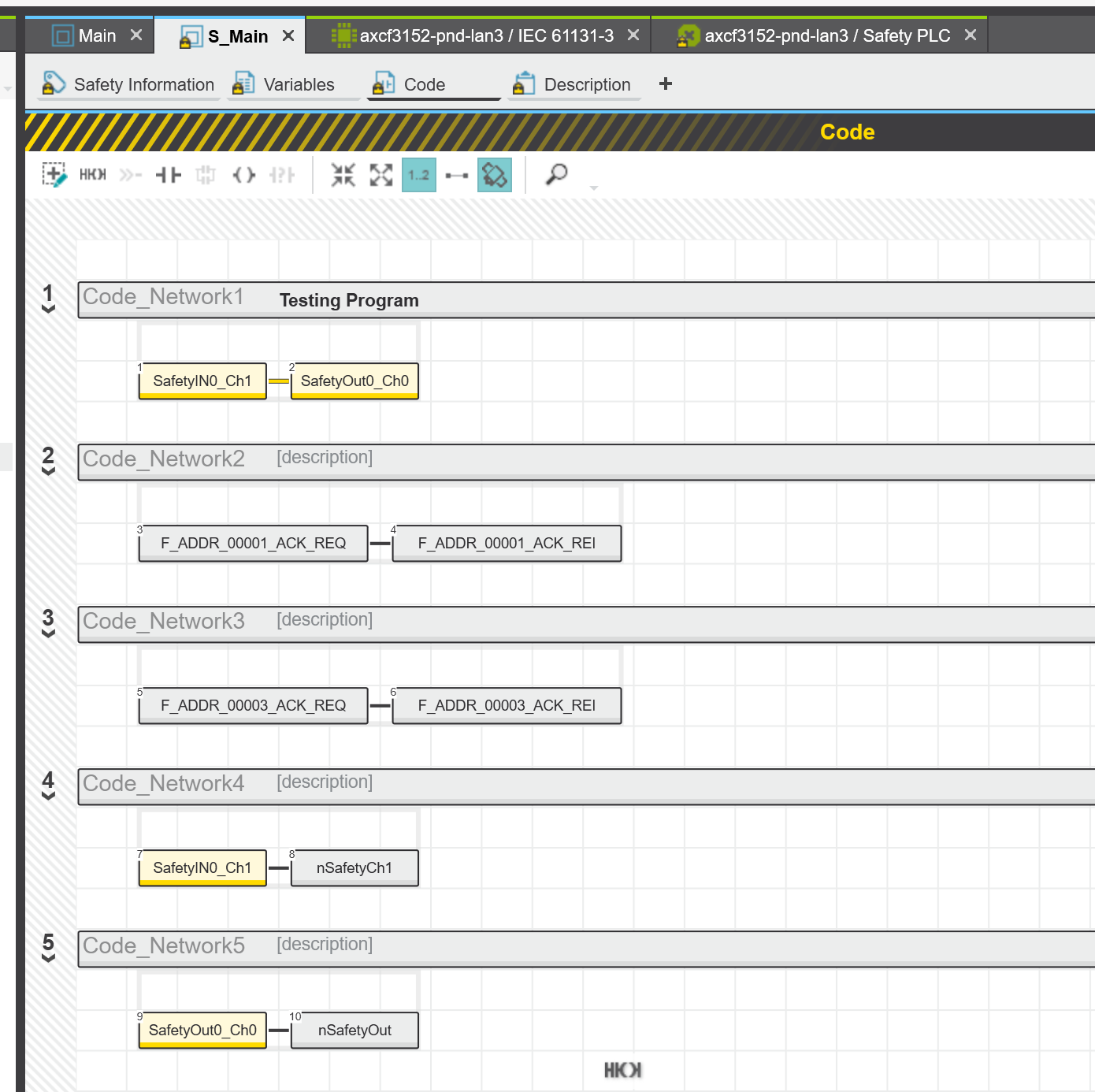
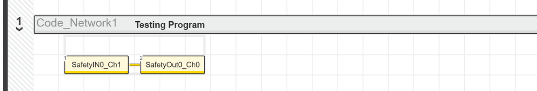
Network1
The Smart Element safety inputs are set to 1-to-2, so Ch1=True indicates that both Ch1 and Ch2 of IN0 have signals. And when both are ON, the Smart Element safety output module outputs OUT0.
Network2
Automatically (ACK_REI) reset if F Device0001 requires ACK (ACK_REQ).

Network3
Automatically resets (ACK_REI) when F Device0003 requires ACK (ACK_REQ).

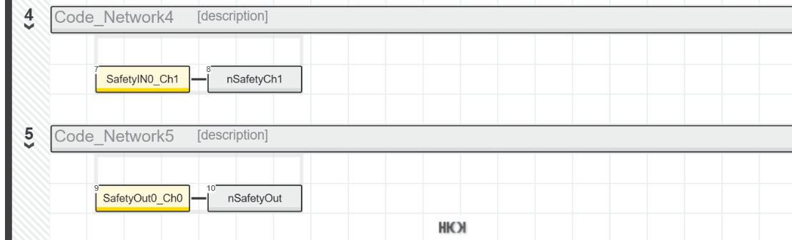
Network4,5
two safety I/O data are transferred to the AXCF3152 variable.
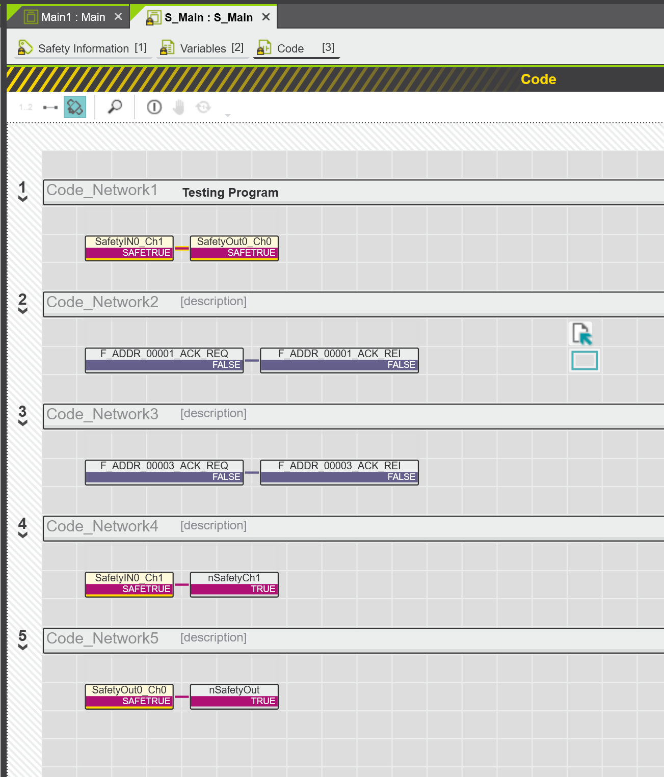
Result
When nSafetyCh1 becomes True, nSafetyOut also becomes True and outputs.

When nSafetyCh1 is False, nSafetyOut is also False and outputs.
Actual program state. (Safety input is False).
Actual program status. (Safety input is True)
You can see the actual operation from this video.