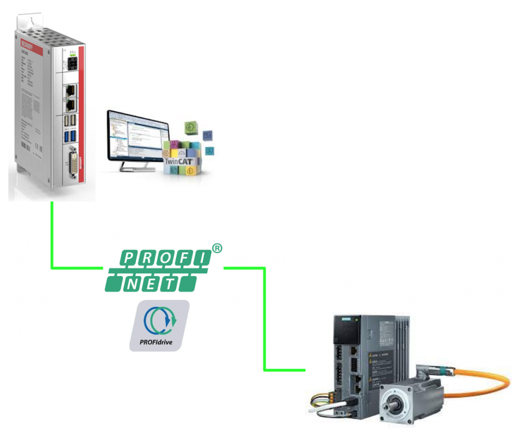
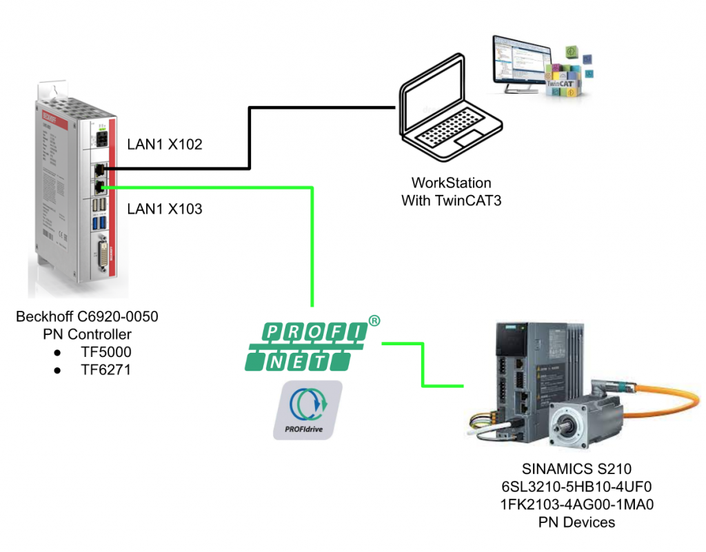
In this tutorial I will show you how to use twincat3 to control the Siemens drive s210 in profinet.I will cover the basic configuration of drive and twincat3 in the part1.
Let’s start !
Thanks!
Because of Beckhoff Japan and mana Design works that lend the devices to me – I can create this post.
Beckhoff Japan
IPC6920-005 was lent by Beckhoff Japan, a Japanese subsidiary of Beckhoff. Founded in 1980, Beckhoff Automation is a German company at the forefront of the introduction of open automation systems based on PC-based control technology.
Beckhoff Japan Corporation Beckhoff Automation Co., Ltd. established its head office in Yokohama in 2011 and the Nagoya office in 2017.

Here is the Home page of Beckhoff Japan.
https://www.beckhoff.com/ja-jp/
Mana Design Works
Siemens SINAMICS S210 was lent by Mana Design Works.
Mana Design Works is an official solution partner of Siemens ,headquartered in Osaka, and always make optimal proposals with Siemens CPUs, HMIs, Drives, Motion Controllers, and SCADA.

Here is the homepage of Mana Design works.
PROFIdrive
PROFIdrive profile complements Profinet/Profibus by allowing drive information to be accessed in a uniform environment and technology for device data, thus decreasing engineering costs when building and designing equipment.
Furthermore, even different manufacturers can control Open-loop and Closed-loop from the same function, which greatly reduces the time and debugging required when designing drive control programs.
Finally, from the drive manufacturer’s point of view, the development course can be reduced because of standard Profile definition.

Base Model
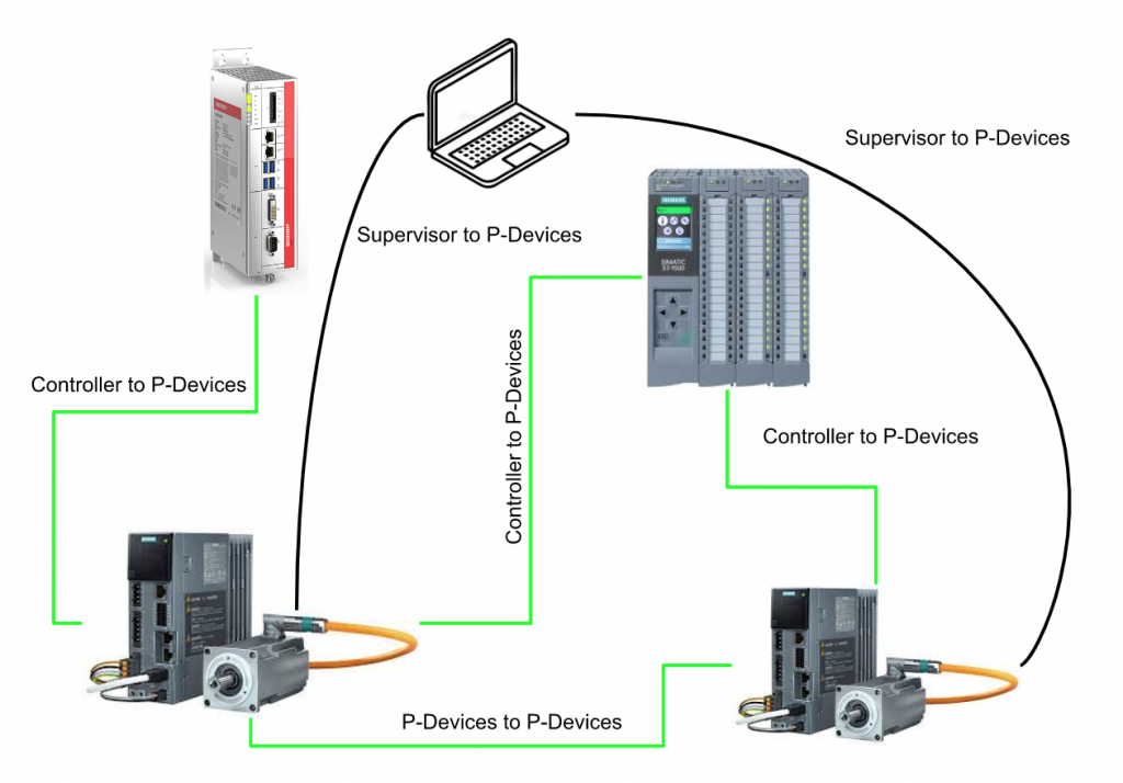
PROFIdrive has 3 classes of basic elements.
Controller
Controller is a device for controlling the drive. From the point of view in the automatic system, the controller is a PLC or a motion controller.
P-Device
P-Device (peripheral device) is the drive’s host device (Closed-loop control, Inverter). The P-Devices are connected to the Controller by Profinet.
Supervisor
Supervisor is an engineering tool that manages P-Devices parameters and Configurations. we can images that Starter/TIA in siemens, TwinCAT3 in Beckhoff, and Somachine in Schneider.
Communication network
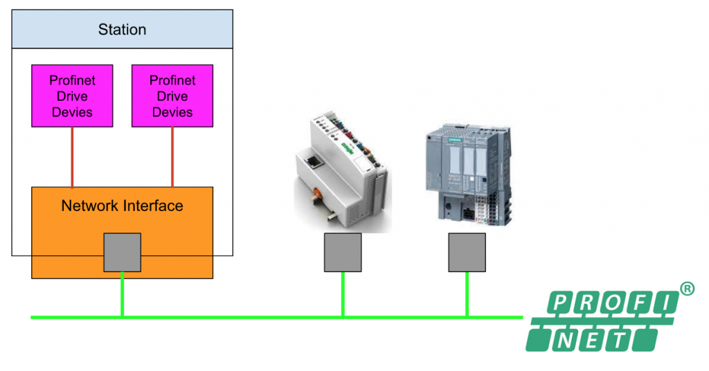
The PROFIdrive device is just one of the Station’s components in the device. Each Station has a Network interface Connector, which physically connects the corresponding Station with the Network and provides Communication services to the device.
Functional Object
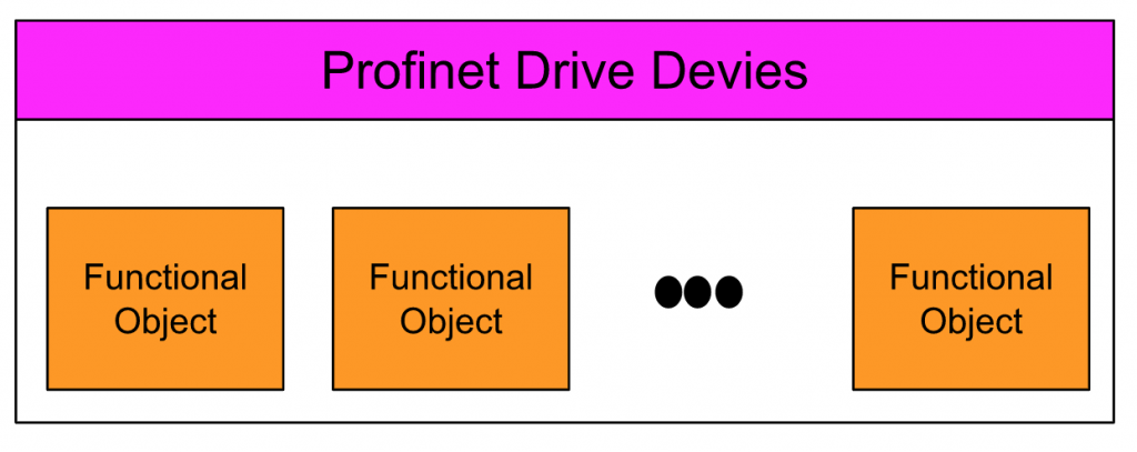
A PROFIdrive Device contains one or more Functional Objects, which are represented in the automation system as logical Objects with special functions.
For example, multiple Functional Objects are constructed by PROFIdrive Device as shown below. If the device is a P-Device, then P-Devices>Drive Object contains Function Objects (Motor, Inverter, Closed loop Current, Speed Control, Input/Output).
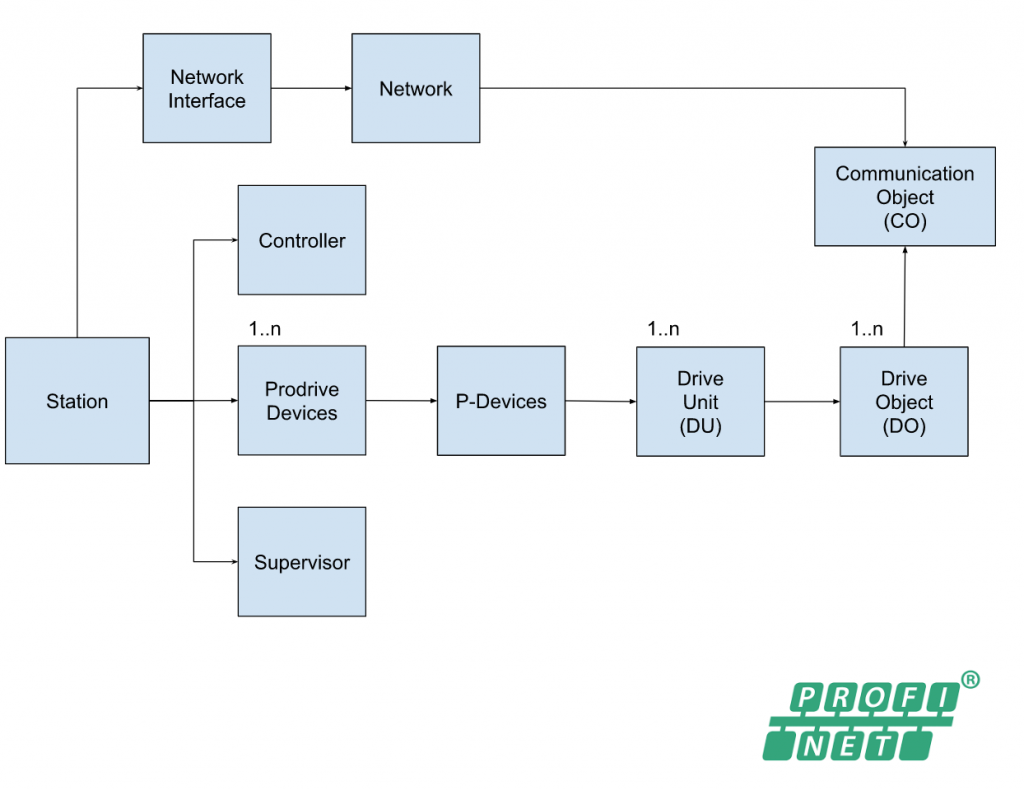
Object Model
The figure below is the Object Model diagram of PROFIdrive. Each station contains a network interface and one or more devices. Its Network Interface connects to other devices in the Profinet network.
As I said earlier, devices are divided into Controller, P-Device and Supervisor.
If the corresponding Station is a P-Device, the P-Device has one or more Drive Units (DU) > And one or more Drive Objects (DO) has one or more Drive Units (DU).
The Communication Object (CO) communicates with the Host Controller over the Network interface and associates with the Function Object.
Layer Model
There are two layers in the PROFIdrive – communication layer and application layer.
As you can see below, the application layer is related to drive object and the communication layer is related to the communication.
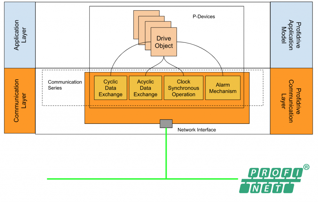
Communication services
In the PROFIdrive base model , these communication services are defined and provided from device function objects.
The format of data is big-endian format.
Cyclic Data Exchange
Cyclic communication is a communication service that transfers the Io data in a fixed time slot.These Io data may be control word, status word , setpoint,actual value,etc.And there are Controller →P-Devices and P-Devices →controllers,two connection relationships inside.
Acyclic Data Exchange
On the other hand, Acyclically communication is used for parameters or firmware download – the task that fixed the time slot is not required. There are also two connections inside – Controller—– P-Device” and “Supervisor – P-Device”.
Alarm Mechanism
Alarm Mechanism service is used to provide the alarm information from device to controller.
And it is a demand -base communication, the updated information is kept in the controller side.
Clock Synchronous Operation
Clock Synchronous Operation service is a feature that grants the task in different devices or function objects that can be executed in the same time (min jitter), but also sends the data correctly in the communication cycle.
In the drive technology, clock cycle synchronous is very base , it is not just for his system , but also for the algorithm inside the drive(for example closed loop speed control), sync between the high level controller and the controller inside the drive
Siemens S210 Servo Drive
SINAMICS S210 servo drives is a one phase servo system that with SIMOTICS S-1FK2 servo motor,connecting by OCC technology (One cable connection)
The power supply of the servo drive is 200..240 1 AC,and the rated power input of the servo motor is from 0.05 … 0.75 kW.
For the fieldbus system , profinet communication interface is provided.
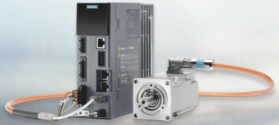
OCC Cable
OCC cable is a technology that integrate the power supply , encoder signal and brake signal into one cable.

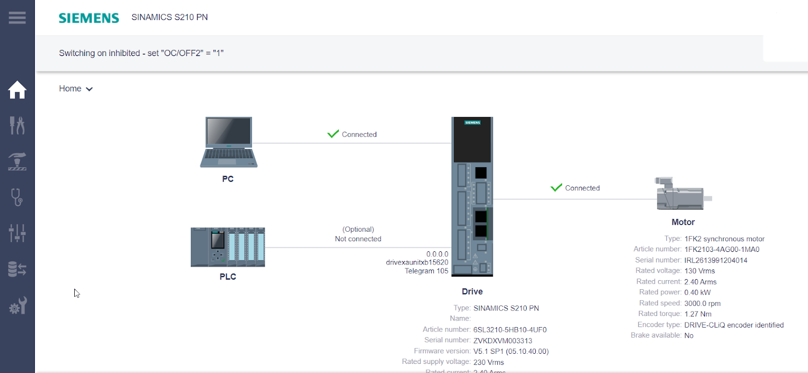
Web Server
Parameter assignment from the drive’s web server becomes easier.It enables functional commissioning of the drive and can be put into operation with just a few clicks.
In addition, the System automatically detects the encoder by reading out the electronic nameplate of the SIMOTICS S-1FK2 servomotor, minimizing operator interaction, e.g. automatic controller optimization with one-button tuning.
- The web server can also be accessed directly from the controller via PROFINET, allowing easy commissioning even in hard-to-reach locations.
- Provides diagnostic capabilities without additional software
- Commissioning and diagnostics can also be performed without cables from a laptop PC, smartphone or tablet.
Diagnose
The diagnosis of s219 can be checked on the Led display on the drive or web server .
Safety Integrated
Thanks to the built-in safety features, the S210 provides application-specific protection for man and machine. Safety features can be used via the fail-safe digital input of the drive (STO and SS1 only) or via PROFINET with PROFIsafe.
Safety Integrated Basic functions
- Safe Torque Off (STO)
- Safe Brake Control (SBC)
- Safe Stop 1 (SS1)
Safety Integrated Extended functions1)
- Safe Stop 2 (SS2)
- Safe Operating Stop (SOS)
- Safely-Limited Speed (SLS)
- Safe Speed Monitor (SSM)
- Safe Direction (SDI)
Profinet
SINAMICS S210 servo drives are equipped with a PROFINET communication interface for connection to the control system, from standardized profiles for connection to higher-level controllers on RT and IRT are supported.
- PROFIdrive profiles
- PROFIsafe profiles with Shared Device
- PROFIenergy
Configuration
Siemens S210 Side
Login to Web Server
X127 is used to connect to the web server from your laptop.
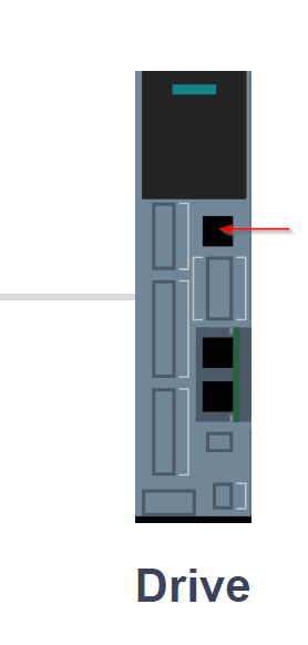
The ip address is 169.254.11.22 .

You can also check the Io address by using Wireshark and capture the LLDP packages.

The login screen is shown.
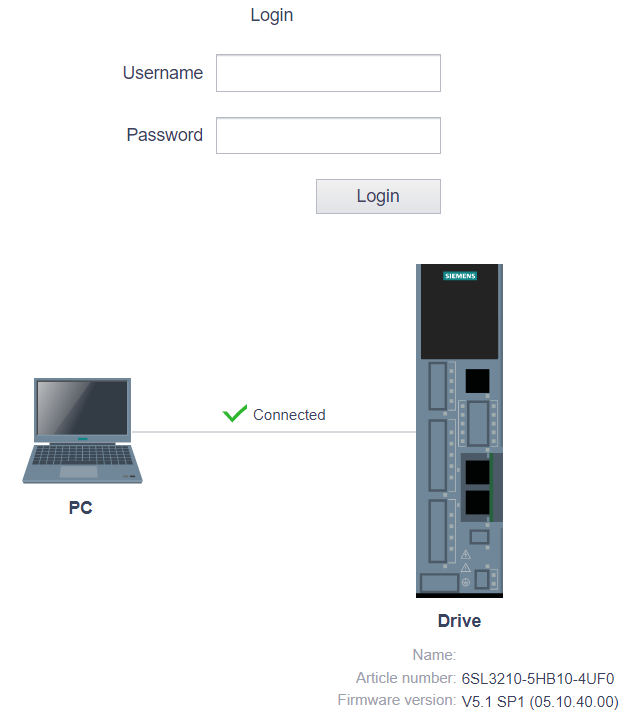
Enter your user name and password to login.

The screen as below is shown while the login is scuessed.
Control Panel
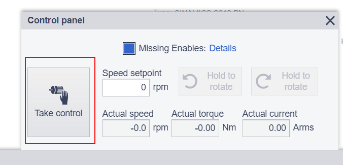
Before we configure the communication with twincat , let ‘s directly control the drive with the control panel in the web server.
Click the control panel in the right corner.

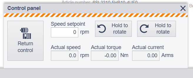
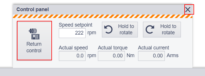
Control panel is displayed and we can take control from our web server.(if profinet network is avatived , take control from web server is not allowed and you need to interrupt the profinet network first).
Click confirm .

The color of the control panel is changed to orange and we can control our drive in the web server now !
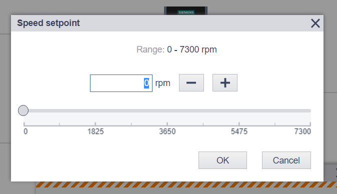
Click the Speed setpoint Field.

Enter the speed setpoint and OK.
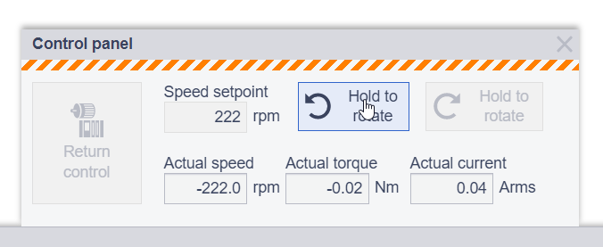
The drive can be rotated if the Hold to Rotate button is pressed.
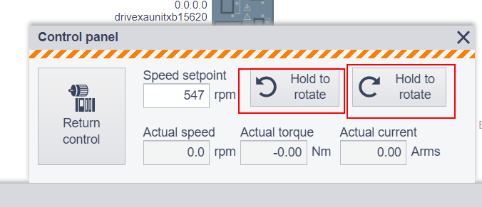
Done! The Motor is rotating!
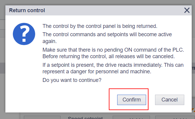
Finally we can press the “Return control” button or “X” button to return the control rights.
Press the confirm button to give back the control rights.
DiagnosticsMessage


Auto Tuning
We can operate the Auto tuning from the S210 web server.
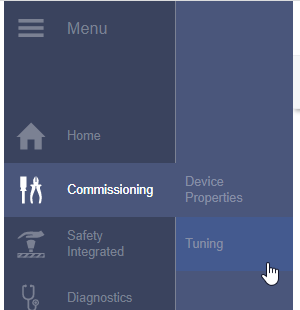
Go to the Commissioning > Tuning.
Press the Take Control button to get the operation right.
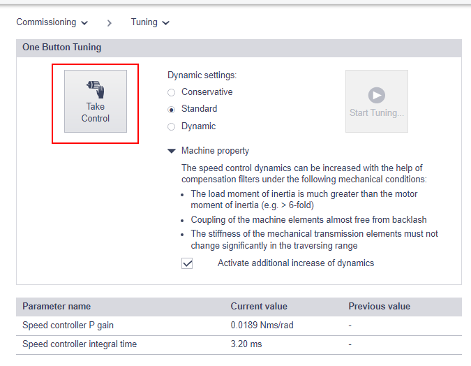
Confirm.

Press the Start tuning button to start the auto tuning.
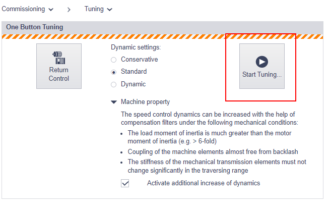
Enter the Rotation limit in the Auto Tuning process>OK.

The auto tuning is like this:
The auto tuning is done if the One Button Tuning successful message is shown.

Press save changes to save your auto-tuning result.
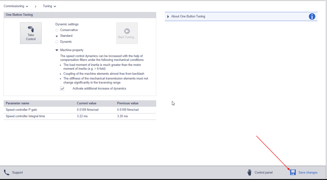
Save.

Done!
TwinCAT3 Side
Downlaod GSDML
Please access this link to download the latest version of the GSDML file.
Add Profinet Controller
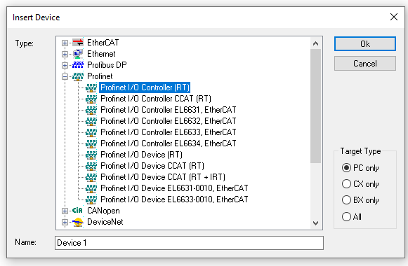
Go to I/O>Devices>Right click>Add New Item.

Choose Profinet I/O Controller(RT)>Ok.
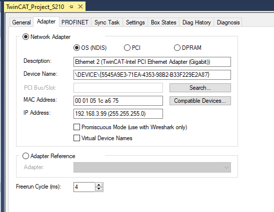
Select the interface that is connected into your profinet network.
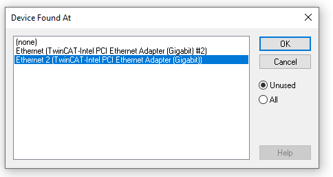
Done.
Configure the PN Controller
Click the Sync Task Tab> select the Special Sync Task option and click the “Create new I/O Task” button.

Create a new task for the PNIO and set the Sync task that is based on 2(1,2,4,8,16..)

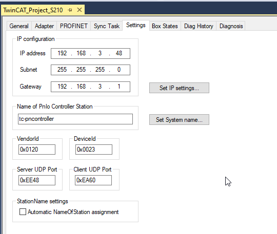
Go to the Settings Tab and Change your Controller IP address > press the Set Ip Setting to confirm.
Add Siemens S210 Drives
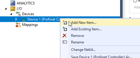
Go to I/O Devices>Right click>Devices>Devices1 and Add new item.
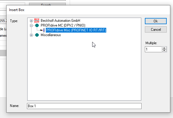
In the last tutorial regarding to the Profinet, we imported the GSDML files from tMiscellaneous option.In this time, we will import the GSDML file fromPROFIdrive MC(DPV2/PNIO)>PROFIdrive Msic[PROFIENT IO RT/IRT].
Import the GSDML file that you downloaded from Siemens website.
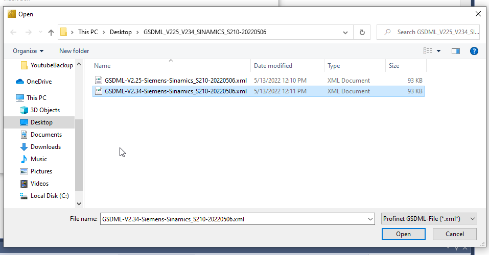
In this GSDML file, we can choose SINAMICS S210 PN V5.1 or SINAMICS S210 PN V5.2 as your configuration.please match to your Drive’s firmware.
In this tutorial, V5.1 is used.

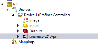
Siemens Sinamics s210 is created.
Configure the S210
Double click the Sinamics-s210-pn object.
Go to General>name to change your Device Name.

Enter the IP address of your S210 drives in the Devices Tab.

Download
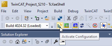
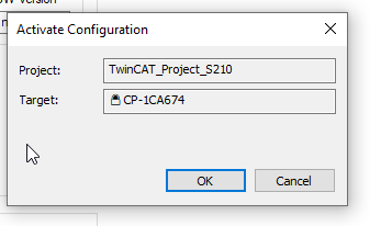
Press Activate Configuration to download your hardware configuration.
OK.
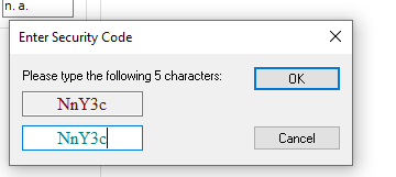
Press yes to shift to the Trial license enter screen.

Enter the magic code to activate your license.
Reset the TwinCAT System.
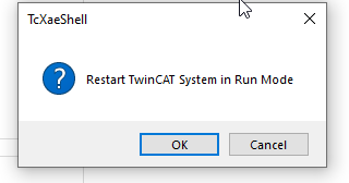
Done.
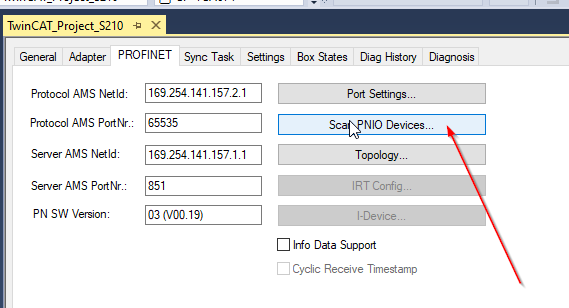
Scan PNIO Devices
Now we can assign the station name.Open the Profinet Controller>PROFINET and click the “Scan PNIO Devices” button.
TwinCAT will search all PN Devices that are inside the profinet network, and you can find your Siemens s210 drives.
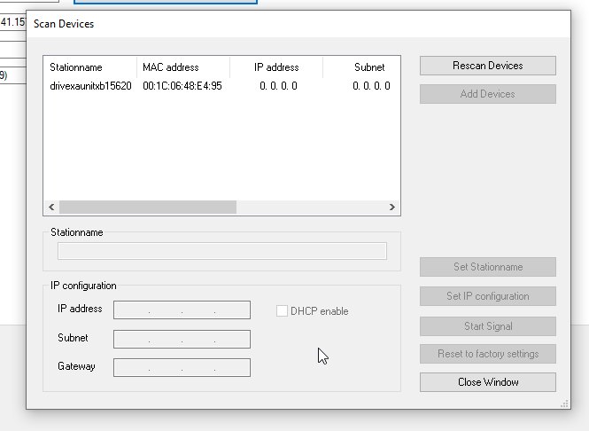
Enter the Station name that you set in the hardware configure and press the “Set Stationname” button to assign the Station name.

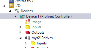
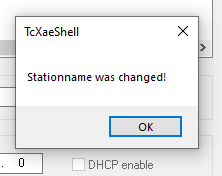
The station name was changed.
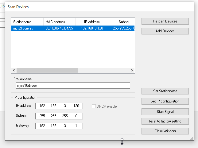
The station name of S210 is changed to mys210drives and twincat assigned the ip address to this PN device.
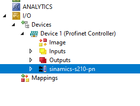
Open the Box States tab ,If “No Error” is displayed in the Box States and “Communication established” is displayed in the BoxDiag – It means the communication is OK!

Add Axis In your Project
Go to Motion>Right Click>Add New Item.
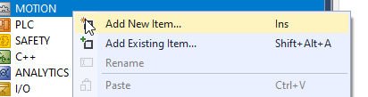
Choose NC/PTP NCI Configuration and OK.
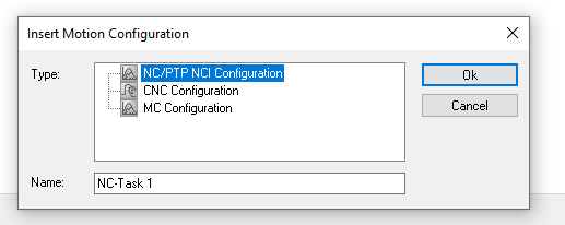
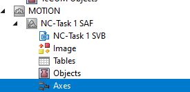
Axes are inserted into your project.
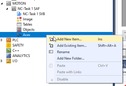
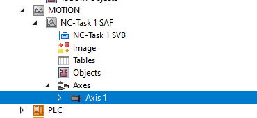
Add NC Axis
Right Click the Axes>Add New Item.
Enter your Axes name and click OK.

Axis is inserted in your project.
Mapping
Open the Settings Tab and link the PROFIdrive IO to the Axis Object.
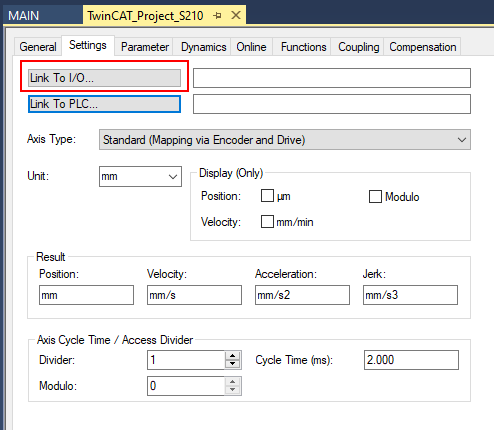
Choose ProfiDrive>OK.
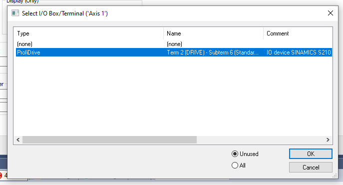
Now the PROFIdrive IO is linked to your axis object.

Parameters
Now is the time to configure the Axis.
Drive
Double click the Drive and set up the drive parameter.

Invert Motor Polarity
We can use this parameter to invert the Feedback value direction of the motor.
FALSE: The feedback value of the encoder will be increased if the motor is in CW.
TRUE:The feedback value of the encoder will be decreased if the motor is in CW.
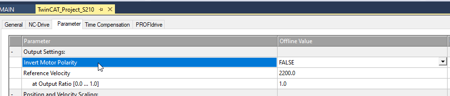
Reference Velocity
Reference to the motor data sheet and set the rated speed.
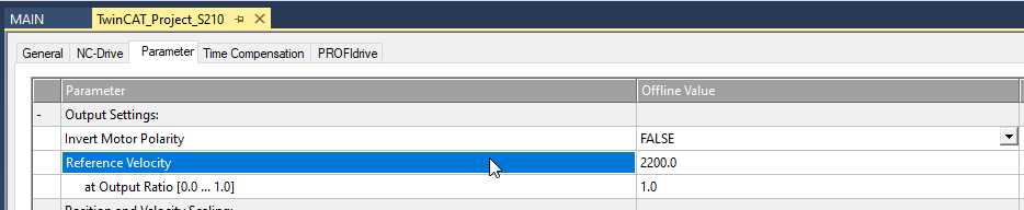
at Output Ratio[0.0..1.0]
It is a very useful parameter when the machine is still in starting up.it can limit the final output percentages.

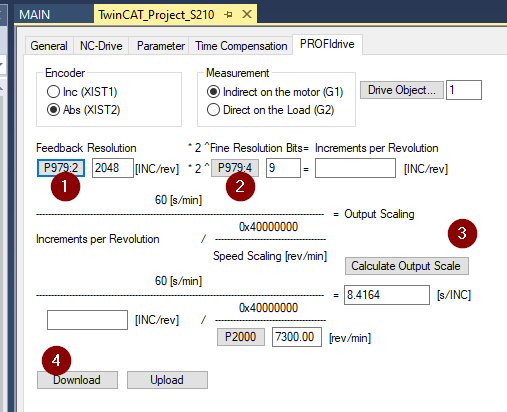
PROFIdrive
Open the PROFIdrive TabのChange to Abs.
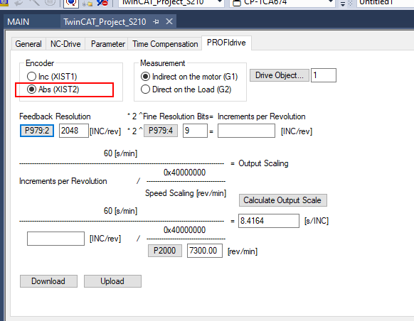
Because the encoder is an absolute type,please choose Abs.
Read the Parameters from P979.2,P979.4,P2000 and click the calculated output scale>download to runtime.
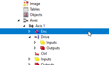
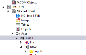
Enc
Double Click the Enc to open the Encoder setting.
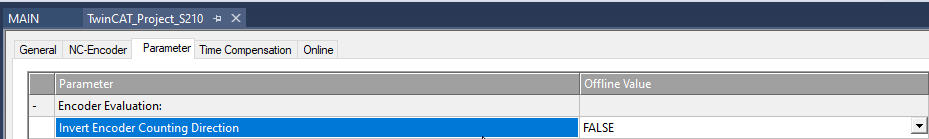
Invert Encoder Counting Direction
FALSE: The direction of Motor rotation and Encoder Count are the same.
TRUE:The direction of Motor rotation and Encoder Count are opposite.
Scaling Factor Numerator and Scaling Factor Denominator (default: 1.0)
The scaling Factor Numerator and Scaling Factor Denominator is the combination
to convert from the Encoder Count to your User unit.
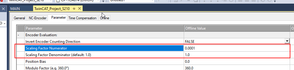
360mm=1rev and 22 bit Encoder is used in this tutorial, So 360 and 41944304.0 are entered here.
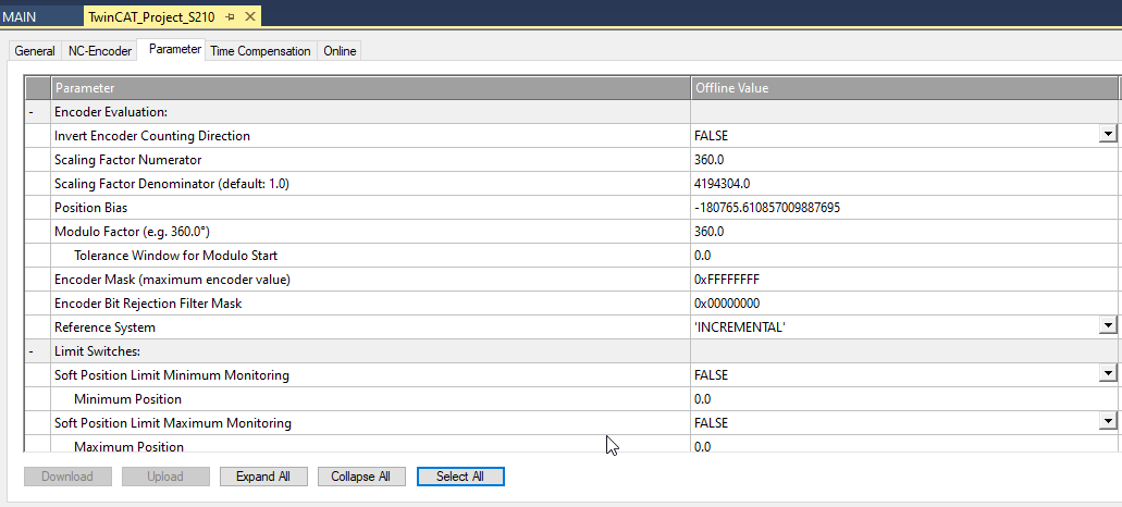
Limit Switches
Please set up the Software Limit that depends on your application.

Axis
Double Click the Axis object to change the parameter of your axis.
Cycle Time(ms)
Go to the Settings Table and you can change the update cycle time.

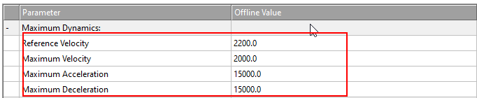
Maximum Velocity
Here is the max speed setting.
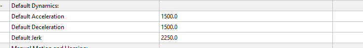
Default Dynamics
Here are the parameters that are used while the Default parameter is passed into MC_XX Function Block.
Manual Motion and Homg
Here are the parameters that are used in the Control Panel.
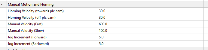
This is the Control Panel.

Position Lag/Position Range/Target Position Monitoring
This Position Lag detection will be a frequency trigger while you are starting up the machine.
And you can change it to false to disable it first.

Position Lag Monitoring
Position Lag is a feature that compares the difference between Setpoint and Actual Value, and an error occurs if Limit is exceeded.
Please adjust Max and Min little by little.
- TRUE: Position Lag Monitoring is enabled
- FALSE: Position Lag Monitoring is disabled
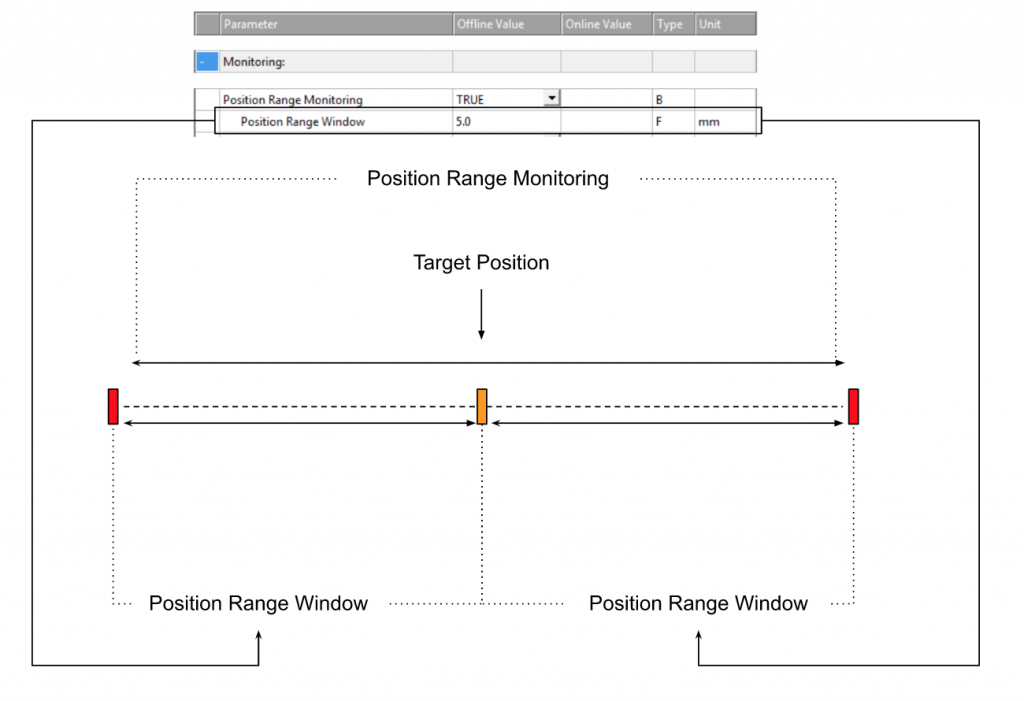
Position Range Monitioring
Variable Axis.Status.InPositionArea:
If the parameter “Position Range Monitoring” is set on TRUE,
variable Axis.Status.InPositionArea will be true while the gap of target position and actual position are in the range of Position Range Monitoring parameters.
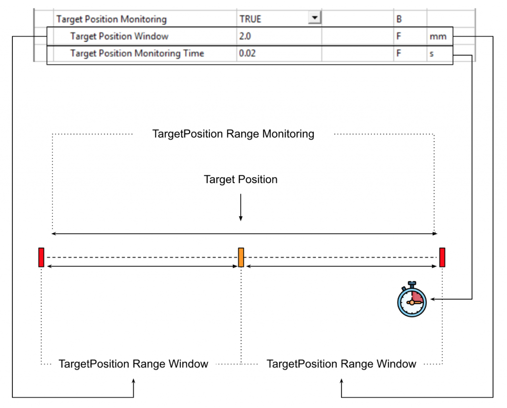
Target Position Monitoring
Target position:
If the parameter “Target Position Monitoring” is set on TRUE,
variable Axis.Status.InTargetPosition will be true while the gap of target position and actual position are in the range of Target Range Monitoring parameter,
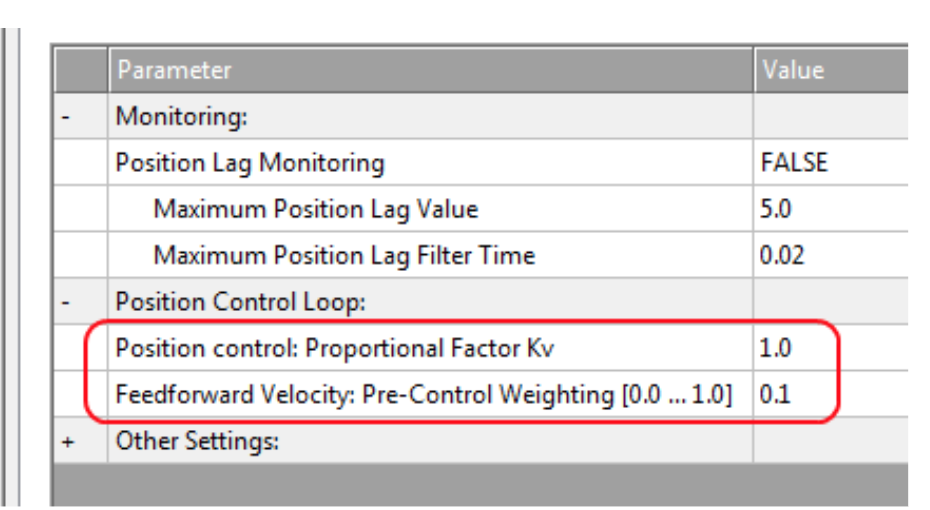
Controller Kv-Factor
Kv Factor is an important variable incorporated into Loop Gain of Position Control. So the variable is to adjust the speed so that the Target position and the Position Error of the current position are 0.
The higher the Kv, the faster the system will adjust, but if it is too large, it may become unstable.
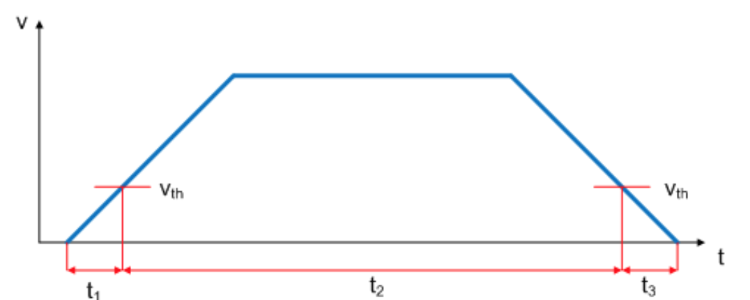
There are two constants P in the parameters, as shown below, which define the standstill range and movement range. Those values can give the Drive starting torque and Braking torque apart from the torque in motion. Kv Factor and Velocity thresholds can be set from 0.0 (0%) to 1.0 (100%).
As shown in the figure below, Velocity’s ramp is limited to a threshold value of 50%. It is OK if the Kv Factor of t1 and t3 is different from the Kv Factor of t2.
And also we can directly adjust the Kv-Factor in the TwinCAT Control Panel.

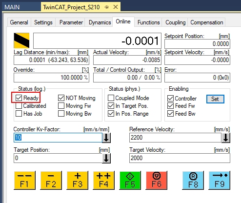
Control Panel
We can open the Control Panel from the Online Tab.

Reset
The F8 Blue button is for the reset operation.

Enable Axis
Press the “Set” Button to enable the Axis.

Controller Checkbox:Enable the axis
Feed Fw Checkbox:Enable the FW direction
Feed Bw Checkbox:Enable the BW direction

StatusがReadyのCheckがあれば、AxisがEnableされた状態です。
Jog+/-
F2 and F3 Button can operate the drive in jog mode at slow speed.

このようです。
Jog++/–
F1 and F4 Button can operate the drive in jog mode at High speed.

The operation is like this.
Go to Target Postiion
Enter your Target Position and Target Velocity >Press F5 to execute the positioning task.

The operation is like this.
Stop
You can also press F6 Stop to stop the task.
