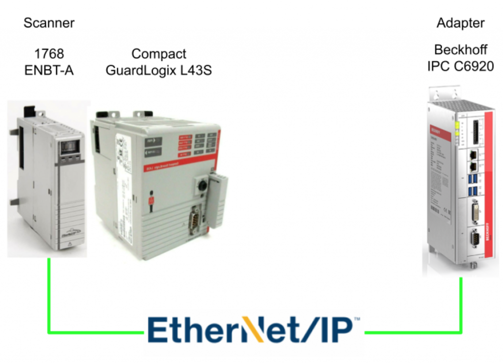
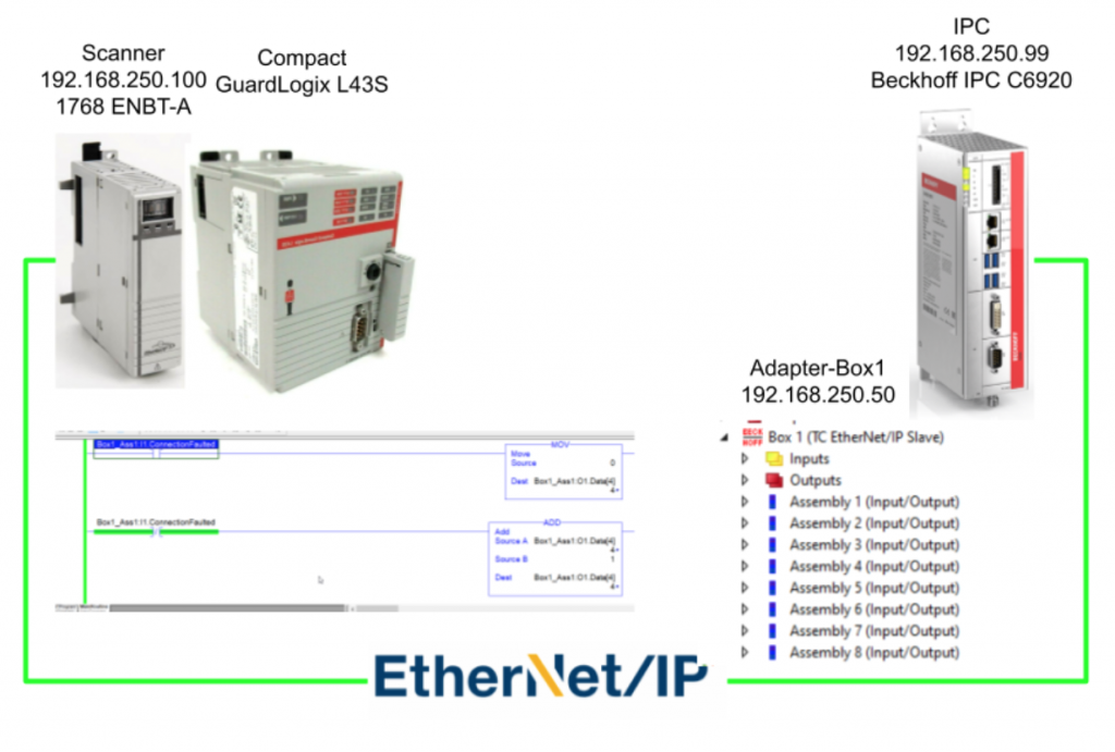
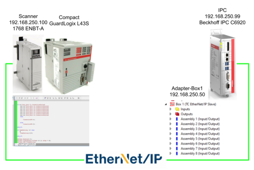
In this Tutorial, I will show you how to configure 8 Assemblies of one Ethernet/IP Adapter in TwinCAT, and Rockwell Compact GuardLogix L43S + 1768 ENBAT-A is used in the scanner side.It is a good practice to create multiple assemblies in TwinCAT – It will allow different scanner to exchange data between in only “ONE” IP address, and you can configure the first Assembly is for Area1 status,the second Assembly is for Area2 Status..etc.(But not more than 8 connections). And I created a program to check the IO consistency in the Rockwell Side(Structured Text is used).
Let’s start!
Thanks!
Because of Beckhoff Japan that lend the devices to me – I can create this post.
Beckhoff Japan
IPC6920-005 was lent by Beckhoff Japan, a Japanese subsidiary of Beckhoff. Founded in 1980, Beckhoff Automation is a German company at the forefront of the introduction of open automation systems based on PC-based control technology.
Beckhoff Japan Corporation Beckhoff Automation Co., Ltd. established its head office in Yokohama in 2011 and the Nagoya office in 2017.

Here is the Home page of Beckhoff Japan.
https://www.beckhoff.com/ja-jp/
Implementation-1
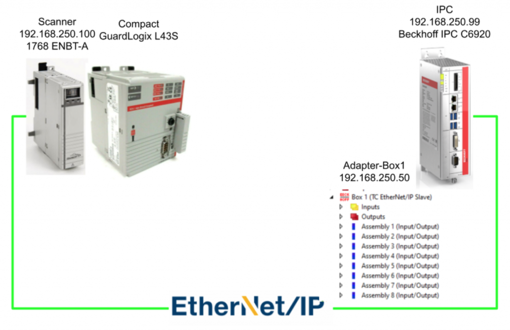
In the first Implementation, I will show you how to configure 8 Assemblies in 1 Adapter – And Each Assembly had 64 bytes.
TwinCAT Side
Let’s configure the TwinCAT Side First.
Choose Target
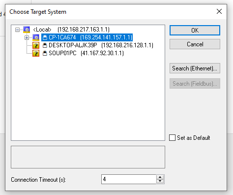
Go to Your project>Choose Target.

Make sure you are connected with the correct IPC.
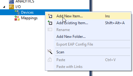
Add Ethernet/IP Adapter
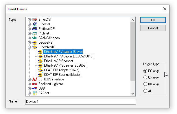
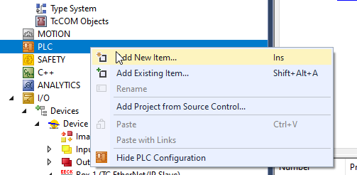
I/O>Devices>Add New Item.
Expand EtherNet/IP>Ethernet/IP Adapter Status>Ok.
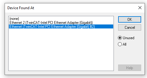
A Device Found AT Popup is shown and please select the Ethernet interface that is connected in the Ethernet/IP Network,
Open the Adapter Tab to Double Check if the Adapter Configuration is correct or not.

Sync Task
Open the Sync Task tab>Select the Special Sync Task to Create new I/O Task.

Enter your Task name.

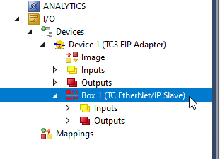
A Task for Ethernet/IP Adapter is configured.

Configure The box
Now we can configure the Ethernet/IP Adapter Connection.
IP
Open the Settings Tab and Enter the IP address and Network Mask.
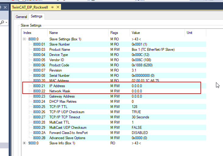
Enter the IP address and Network Mask in item 8000:21 and 8000:22.

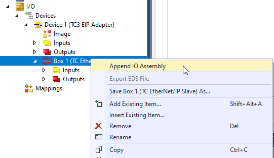
Append IO Assembly
Right Click the Box>Append IO Assembly to insert a new Assembly.
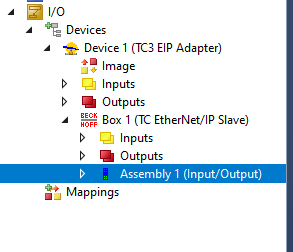
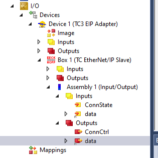
“Assembly 1(Input/Output)” is inserted.
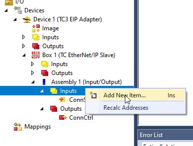
Add New Item-INPUT
By Default, Twincat will not create any input and output data and we can create any sizes of data.Right Click the Inputs>Add New Item.
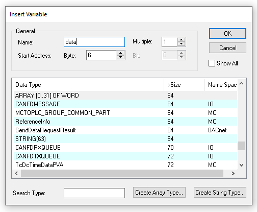
Enter the variable Name>choose Word as the Data Type>Create Array Type.

32 words are configured in here.

Add New Item-OUTPUT
Just do the same operation with the output variables.Right click the output field>Add New Item.

Enter the Data name>choose Array[0..31]of WORD>OK.
Output Variable is created also.
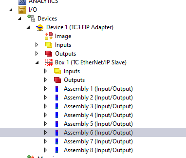
Add More Assembly!
Now we only need to copy the first Assembly and paste it again and again – Be careful that only 8 connections of Assembly can be established at the same time.
Export EDS
Right Click the Box1>Export EDS File to export the EDS File.
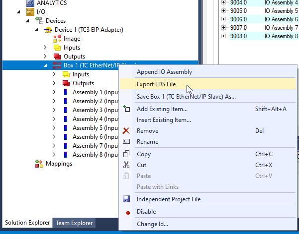
Choose Yes.

Select your Export Path.
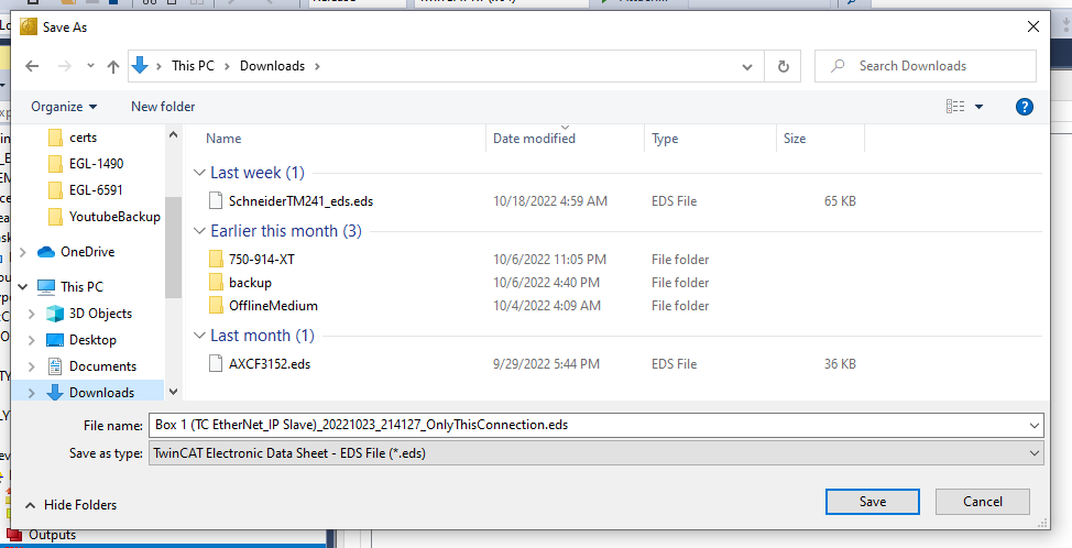
Done!

Add PLC
PLC>Add New Item.
Choose Standard PLC Project and Add a new PLC Object.
ADD DUT
Because there are 8 Assemblies configured in my project, It is better to create a DUT to save our time.Right Click>Add>DUT.
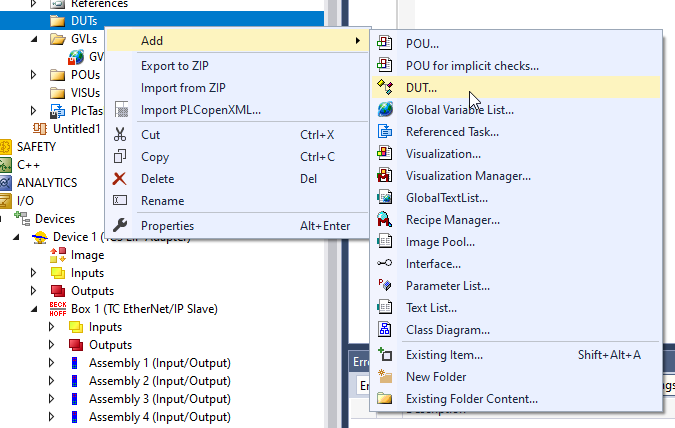
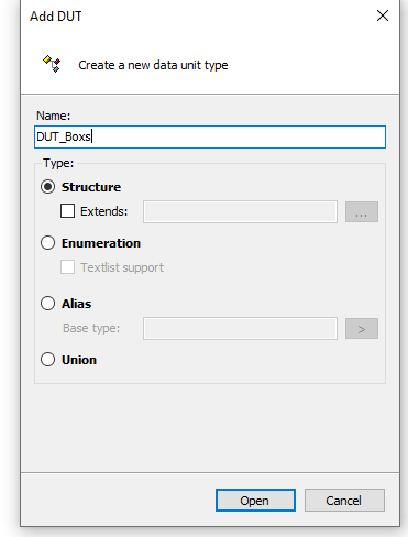
Enter the DUT Name>Select Structure>Open.
Inside the DUT, array[0..31]of Process Input and Output data are defined , and a process input variable of UDINT is also created – it is used to link the Connection status variable of the Assembly.
| TYPE DUT_Boxes : STRUCT InData AT %I* :ARRAY[0..31]OF WORD; OutData AT %Q* :ARRAY[0..31]OF WORD; ConnState AT %I* :UDINT; END_STRUCT END_TYPE |
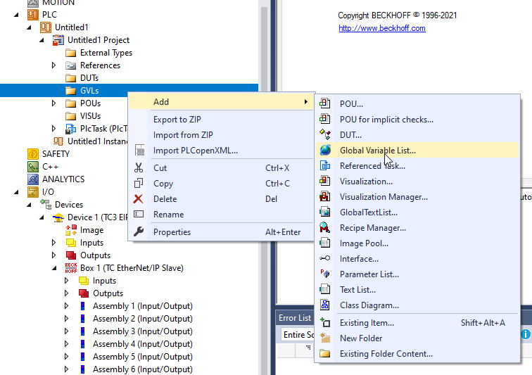
ADD GVL
Now we can create the Global Variable List(GVL) to define the variable.
| {attribute ‘qualified_only’} VAR_GLOBAL Boxes :ARRAY[1..8]OF DUT_Boxes; END_VAR |
PROGRAM
Inside the Main program, we only need to return all the input data back to output data – just like a loop back. The IO verification program will be taken care of by Rockwell at this time.
| PROGRAM MAIN VAR i,j :DINT; END_VAR FOR i:=1 TO 8 DO FOR j:=0 TO 31 DO GVL.Boxes[i].OutData[j]:=GVL.Boxes[i].InData[j]; END_FOR; END_FOR |
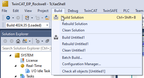
Build
Build>Build Solution to compile your project.
Link Variables
Finally we can Link these variables to Process Input/Output.
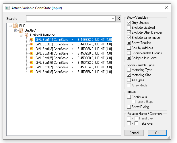
Inputs-ConnState
The first time is the ConnState variable – it will indicate the connection status of the following Assembly.
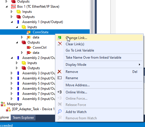
Choose the first element if you can trying to link the First Assembly.
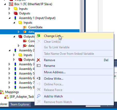
Inputs-data
Then we can Link the input data – because the variable that I created in the GVL is 100% the same as Process Input data, we can directly map it.
Outputs-data
Finally we can Link the Output data – because the variable that I created in the GVL is 100% the same as Process Input data, we can directly map it.

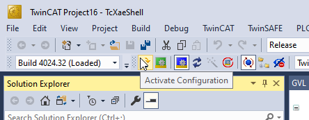
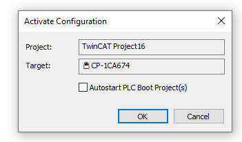
Activate Configuration
Press Activate Configuration to download the Hardware Configuration to TwinCAT Runtime.
OK.
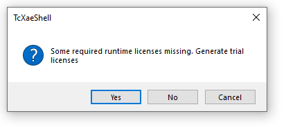
Press yes if some runtime licenses are missing.
Enter the magic Code.
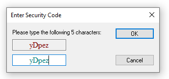
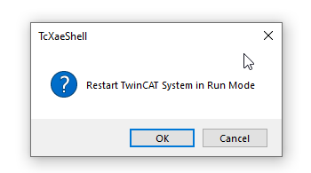
Press Ok to restart the Runtime.
Login
Press Login to download the user program.
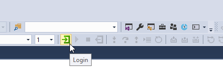
Yes.

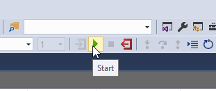
Start
Finally we can press the start button to switch the Program to Run Mode.
Rockwell Side
Now is the time to configure the Rockwell Side.
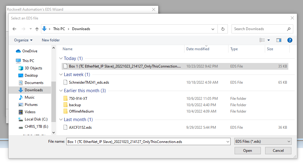
Import EDS File
Please follow this tutorial to import the EDS File.
Choose the EDS file that was exported in the previous step.
Add TwinCAT Adapter
Now we can insert the beckhoff twincat Ethernet ip adapter in the hardware Configuration.RIght click the 1768-ENBT/A>Press New Module.

Search Beckhoff .
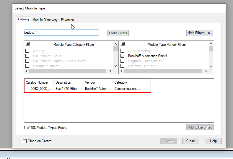
Choose this Adapter>Create.

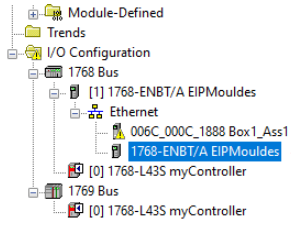
Box1 is inserted in your network.
Configure IP Address
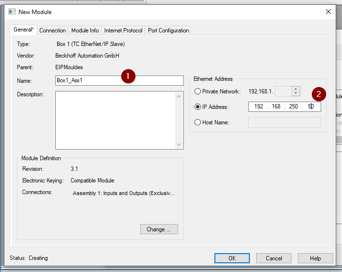
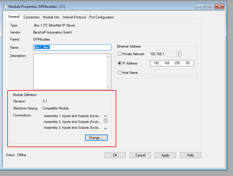
Double Click the Adapter that you inserted in the previous step.
Enter the Adapter Name and Configure the IP address.
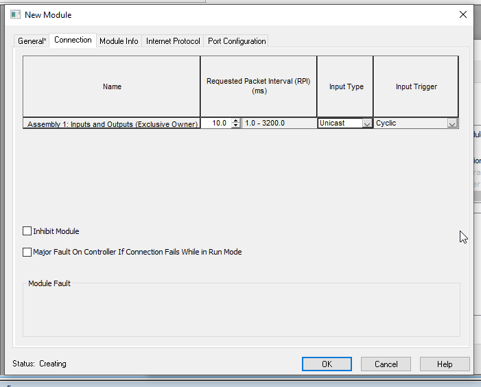
Open the Connection Tab – and you can see the connection of Assembly 1 is configured as Exclusive owner.
Configure Connections
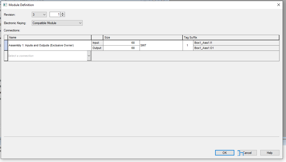
Go back to the General Tab and press the change button to modify the connection.

The Connection modification screen is shown.
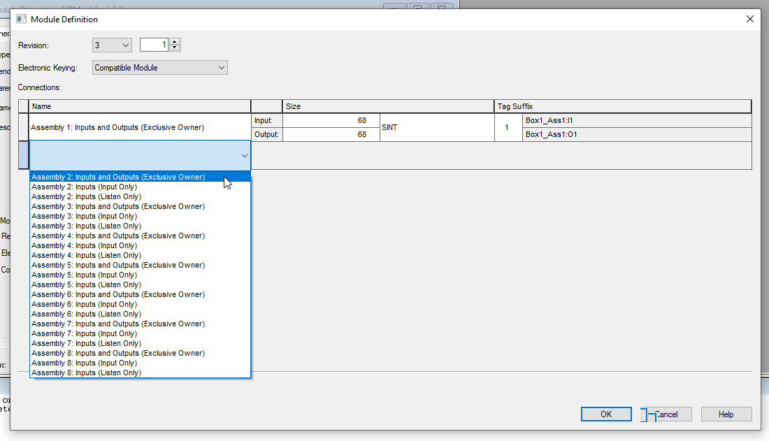
Select the Drop down List > Choose Assembly 2 Inputs and Outputs(Exclusive Owner) as the second connection.
Done!A new connection is created.
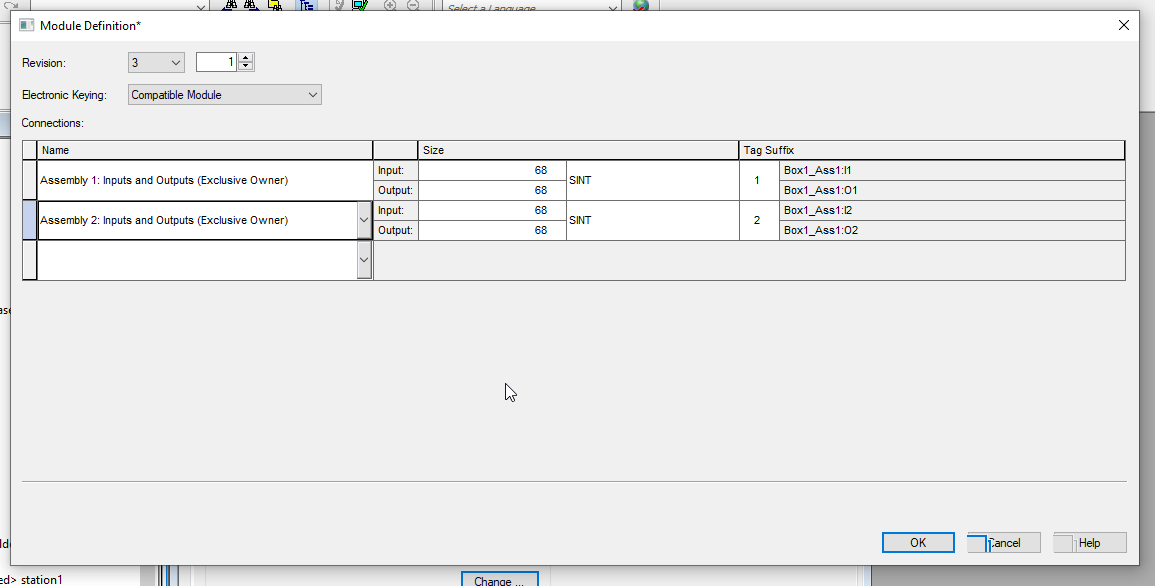
Just do the same step for the other 6 connections.
Go back to the General Tab , and you can see all the connections are configured.
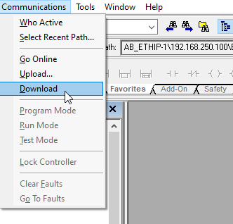
Download
Go to Communications >Download to Download the project to CPU.
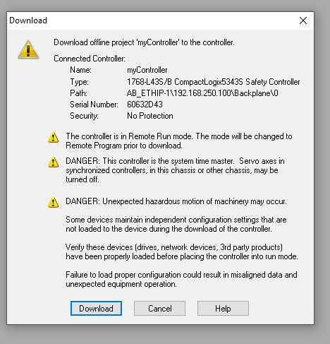
Press Download button.
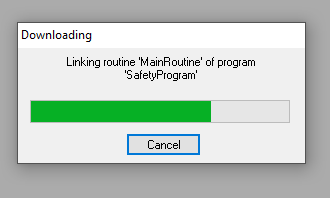
Please wait a second..
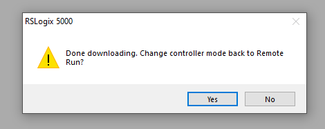
Done!Now we can remote change back the system to run mode.
Result
As you see the I/O OK LED is Green! The connection between Rockwell PLC and TwinCAT is established.

Implementation-2
In the second Implementation, I will make a sample Ladder program to check the connection status and send some data from Rockwell CPU to Beckhoff IPC.
Rockwell Side
Controller Tags
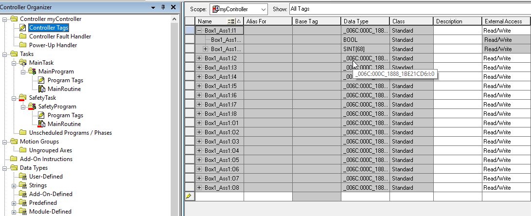
In the Controller Tags , variables of Box1 are automatically created by RSLogic5000.
Program
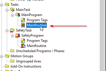
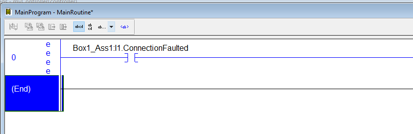
Now we can create some Ladder Program. Open the MainRoutine.
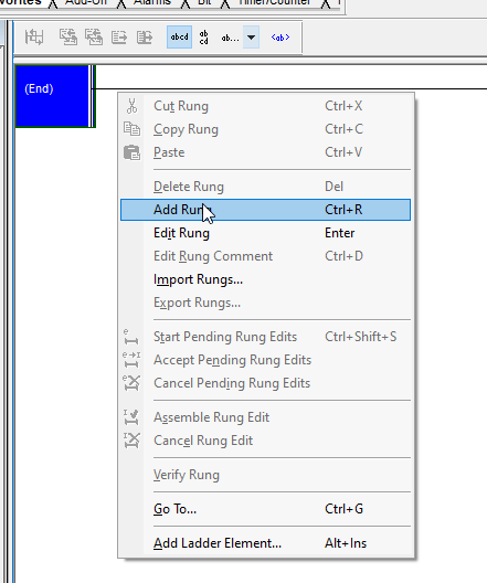
Right Click the End Line>Add Run to create a new Rung.
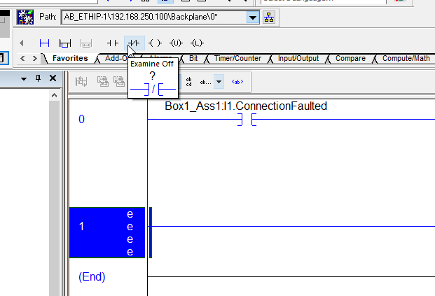
Drop the NO Contact to Rung0.

A NO Contact is inserted in Rung0.

And we can Enter the ConnectionFaulted variable in here – This variable will be true while the connection had some problems.
And I would like to reset the output data while the connection between TwinCAT is fail.
Select “Move/Logical”>Drop the MOV instruction to Rung0.

a move block is inserted in the end of Rung0.
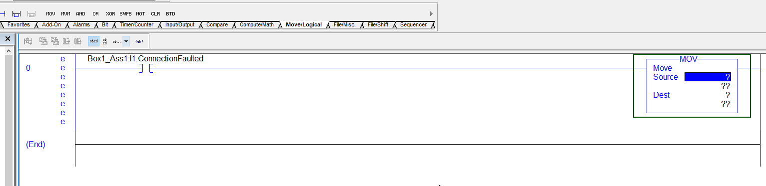
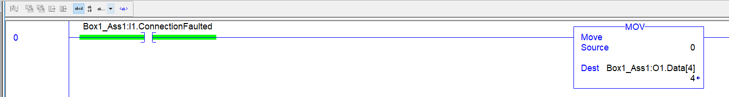
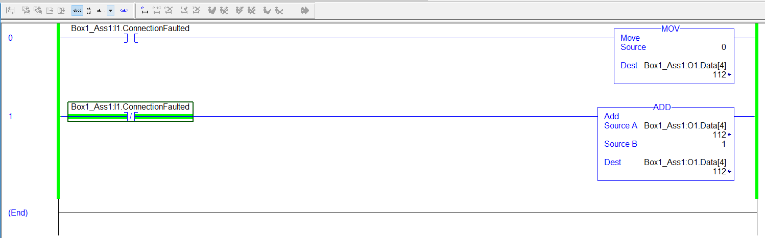
Enter “0” in the Source parameter and Box1_Ass1:O1:Data[4] in the Dest parameter.
Let’s create one more Rung for the condition with ConnectionFaulted=False.
Right Click the End Rung>Add Rung to create a new Rung.
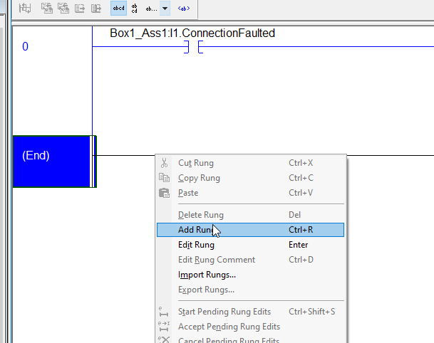
Rung1 is inserted!
Let’s drop a NC Contact into Rung1.

Assign ConnectionFaulted variables for this device.

I would like to increase the output cyclically while the connection is established.
Select the “Compute/Math”> Drop the Add instruction.

ADD block is inserted – Assign Box1_ASS1:O1 as the Source A, Constant 1 as the Source B, and Assign Assign Box1_ASS1:1 as the Dest. The Value will plus 1 itself.

Result
Download the project and check the result – as you see the Output value is increased while the connection is established.
Switch back to the TwinCAT Side, The current value of InData[0] is updated in every Cycle.

Implementation-3
Here is our last Implementation – I will create a Verification program to check the consistency of the IO Data.
Rockwell Side
Instruction Memo
Here are the Instructions that were used in this project – and I will memo how to use it.
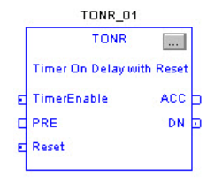
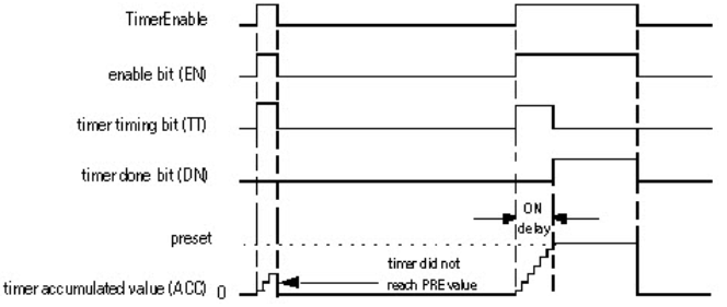
TONR
TONR is a Resettable Delay ON Timer.
Input Parameters
| Name | Data Type | Description |
| EnableIn | BOOL | Function Block:If cleared, the instruction does not execute and outputs are not updated. If set, the instruction executes.Default is set. Structured Text:No effect. The instruction executes. |
| TimerEnable | BOOL | If set, this enables the timer to run and accumulate time.Default is cleared. |
| PRE | DINT | Timer preset value. This is the value in 1 msec units that ACC must reach before timing is finished. If invalid, the instruction sets the appropriate bit in Status and the timer does not execute.Valid = 0 to maximum positive integer |
| Reset | BOOL | Request to reset the timer. When set, the timer resets.Default is cleared. |
Output Parameters
| Name | Data Type | Description |
| EnableOut | BOOL | The instruction produced a valid result. |
| ACC | BOOL | Accumulated time in milliseconds. |
| EN | DINT | Timer enabled output. Indicates the timer instruction is enabled. |
| TT | BOOL | Timer timing output. When set, a timing operation is in progress. |
| DN | BOOL | Timing done output. Indicates when accumulated time is greater than or equal to preset. |
| Status | DINT | Status of the function block.Status.01:The instruction detected one of the following execution errors. This is not a minor or major controller error. Check the remaining status bits to determine what occurred. Status.02:The preset value is invalid. |
Flow
Example
| TONR_01.Preset := 500; TONR_O1.Reset := reset; TONR_01.TimerEnable := limit_switch1; TONR(TONR_01) timer_state := TONR_01.DN; |
COP
The COP copies the value(s) in the Source to the values in the Destination. The Source remains unchanged.

Parameters
| Name | Data Type | Description |
| Source | SINT/INT/DINT/REAL/structure | initial element to copyImportant: the Source and Destination operands should be the same data type, or unexpected results may occur |
| Destination | SINT/INT/DINT/REAL/structure | initial element to be overwritten by the SourceImportant: the Source and Destination operands should be the same data type, or unexpected results may occur |
| Length | DINT | number of Destination elements to copy |
Example
| COP(array_4[0],array_5[0],10); COP(timer_1,array_timer[5],1); |
Add New Routine
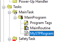
Structure Text is used for this program.Right Click the MainProgram>New Routine.

Enter the Routine Name and Choose Structured Text as the type>OK.

A new routine is created.
Change Routine
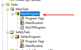
Then we need to change the call configuration.
Right Click the MainProgram>Properties.
The Assigned Routine is “MainRoutine” and we need to change it to “MySTPRogram”.

Select the Drop List from Main>Choose MySTProgram.
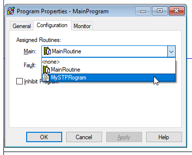
Done!

MySTProgram
Now we can configure the Program.
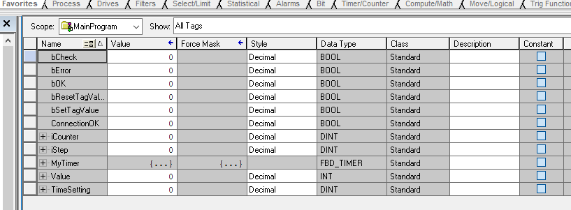
Program Tags
Here are the variables that are used in this program.
- bCheck:Trigger the Check program
- bError:Output Data and Input Data are not consistence
- bOK:Output Data and Input Data are consistence
- bResetTagValue:Reset the Output Data
- bSetTagValue:Set the Output Data Value
- iCounter:using in for loop
- iStep:the Case step Control
- MyTimer:The Timer before IO Verification
- Value:The base value that write to output
- TimeSetting:The Time before IO Verification
PROGRAM
Check the IO Connection Status>Reset all Flags>Write some value to Output>Wait Delay Timer ON>check the IN/OUT Data consistency>Loop Back.
if not Box1_Ass1:I1.ConnectionFaulted and not Box1_Ass1:I2.ConnectionFaulted and not Box1_Ass1:I3.ConnectionFaulted and not Box1_Ass1:I4.ConnectionFaulted and not Box1_Ass1:I5.ConnectionFaulted and not Box1_Ass1:I6.ConnectionFaulted and not Box1_Ass1:I7.ConnectionFaulted and not Box1_Ass1:I8.ConnectionFaulted then ConnectionOK:=1; else ConnectionOK:=0; end_if; if TimeSetting <=0 then TimeSetting:=100; end_if; MyTimer.EnableIn:=1;MyTimer.TimerEnable:=iStep= 30 or iStep = 65;MyTimer.PRE:=TimeSetting; TONR(MyTimer); case iStep of 0: if ConnectionOK and not bError then iStep:=10; end_if; 10: bOK:=0; bSetTagValue:=1; iStep:=20; 20: if not bSetTagValue then iStep:=30; end_if; 30: if MyTimer.Dn then iStep:=40; end_if; 40: bCheck:=1; if bOK then iStep:=50; bCheck:=0; end_if; if bError then iStep:=999; end_if; 50: bResetTagValue:=1; iStep:=60; 60: if not bResetTagValue then iStep:=65; end_if; 65: if MyTimer.Dn then iStep:=70; bOK:=0; end_if; 70: bCheck:=1; if bOK then iStep:=10; bCheck:=0; end_if; if bError then iStep:=999; end_if; 999: bCheck:=0; bOK:=0; iStep:=0;end_Case; if bCheck and not bError then for iCounter:=4 to 67 do if Box1_Ass1:O1.Data[iCounter] <> Box1_Ass1:I1.Data[iCounter]then bError:=1; elsif Box1_Ass1:O2.Data[iCounter] <> Box1_Ass1:I2.Data[iCounter] then bError:=1; elsif Box1_Ass1:O3.Data[iCounter] <> Box1_Ass1:I3.Data[iCounter] then bError:=1; elsif Box1_Ass1:O4.Data[iCounter] <> Box1_Ass1:I4.Data[iCounter] then bError:=1; elsif Box1_Ass1:O5.Data[iCounter] <> Box1_Ass1:I5.Data[iCounter] then bError:=1; elsif Box1_Ass1:O6.Data[iCounter] <> Box1_Ass1:I6.Data[iCounter] then bError:=1; elsif Box1_Ass1:O7.Data[iCounter] <> Box1_Ass1:I7.Data[iCounter] then bError:=1; elsif Box1_Ass1:O8.Data[iCounter] <> Box1_Ass1:I8.Data[iCounter] then bError:=1; end_If; end_for; if not bError then bOK:=1; end_if; end_if; if bSetTagValue or bResetTagValue then for iCounter:=4 to 67 by 2 do if bSetTagValue then COP(iCounter,Box1_Ass1:O1.Data[iCounter],2); Value:=iCounter*10; COP(Value,Box1_Ass1:O2.Data[iCounter],2); Value:=iCounter*20; COP(Value,Box1_Ass1:O3.Data[iCounter],2); Value:=iCounter*30; COP(Value,Box1_Ass1:O4.Data[iCounter],2); Value:=iCounter*40; COP(Value,Box1_Ass1:O5.Data[iCounter],2); Value:=iCounter*50; COP(Value,Box1_Ass1:O6.Data[iCounter],2); Value:=iCounter*60; COP(Value,Box1_Ass1:O7.Data[iCounter],2); Value:=iCounter*70; COP(Value,Box1_Ass1:O8.Data[iCounter],2); end_if; if bResetTagValue then Value:=0; COP(iCounter,Box1_Ass1:O1.Data[iCounter],2); COP(iCounter,Box1_Ass1:O2.Data[iCounter],2); COP(iCounter,Box1_Ass1:O3.Data[iCounter],2); COP(iCounter,Box1_Ass1:O4.Data[iCounter],2); COP(iCounter,Box1_Ass1:O5.Data[iCounter],2); COP(iCounter,Box1_Ass1:O6.Data[iCounter],2); COP(iCounter,Box1_Ass1:O7.Data[iCounter],2); COP(iCounter,Box1_Ass1:O8.Data[iCounter],2); end_if; end_for; bSetTagValue:=0; bResetTagValue:=0;end_if; |
Result
TwinCAT3 Side
Here is the Result in TwinCAT Side.You can see the ConnState Variable=0,It means that the connection is OK , and some values are written in the Process Input.
Rockwell Side
As you see ,Values are refreshed when there is no error.

If Error..
if the input data is not equal to the output data, bError=True and the step will be 0.

Source Project
Please download the source project from this link:
https://github.com/soup01Threes/TwinCAT3/blob/main/TwinCAT_EIP_Rockwell.tnzip