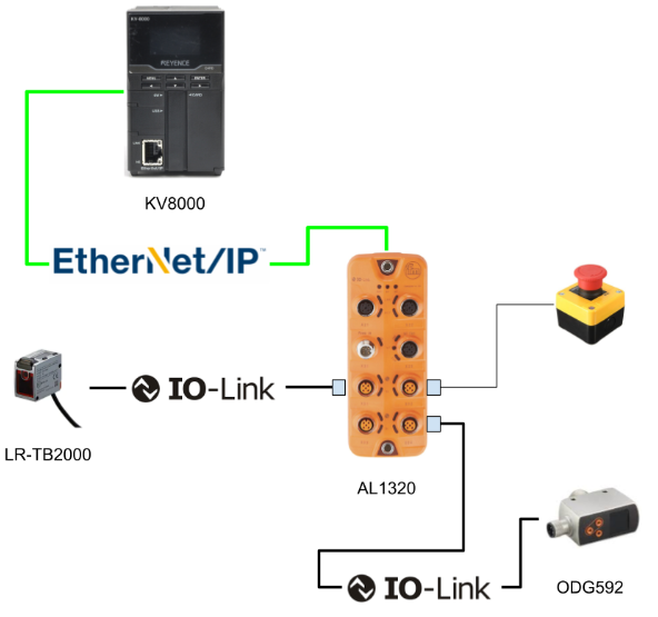
In this article, an Ethernet/ip Scanner will be set up from a Keyence KV8000 and connected to an IFM AL1320, Port 1 and Port 4 will be connected to a Keyence LR-TB2000 IOLINK sensor and an IFM ODG592 IOLINK sensor, Port 2 will be built to provide digital input and Port 3 will be built to provide digital output.
Let’s start!
Thanks!
This article was made possible thanks to the loan of equipment from ifm efector co. ltd. Thank you very much.
ifm efector co. ltd.
ifm was founded in Germany in 1969 as a sensor specialist with the company philosophy “ifm-Close to you”. Today ifm is a large company with more than 7,000 employees in over 95 countries and is widely recognised worldwide as a pioneer in IO-Link, the key to the IoT.

This is the homepage of IFM.
Reference Link
Implementation
IFM Side
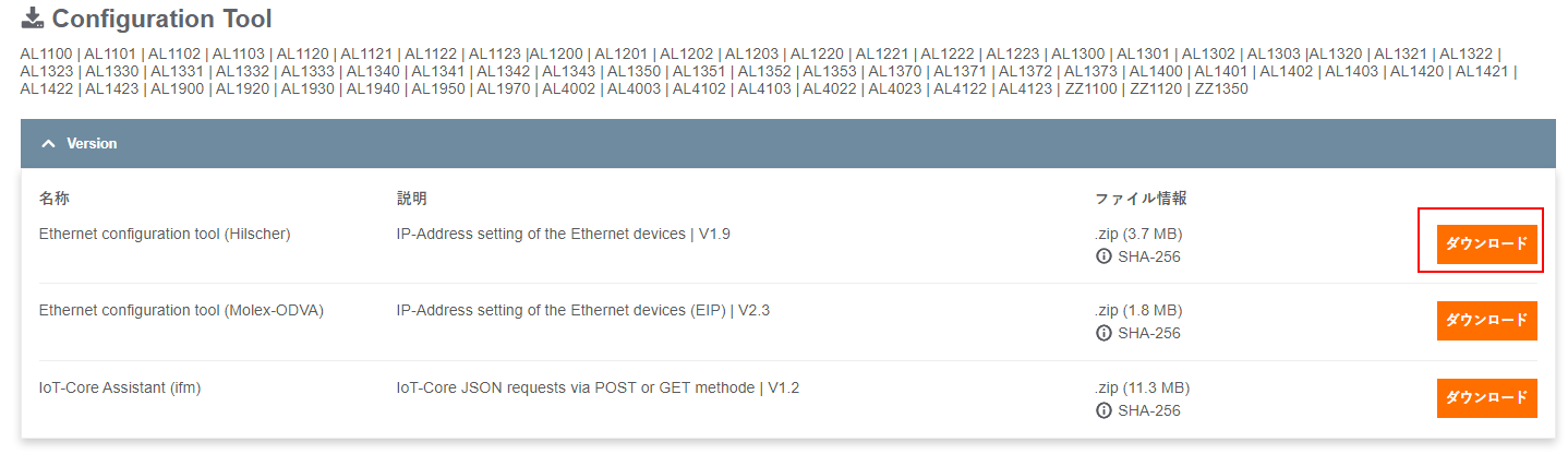
Download Configuration Tools
Download the Configuration Tools from the IFM Homepage.
https://www.ifm.com/jp/ja/product/AL1320?tab=documents
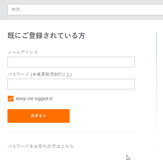
If you don’t have an Account, please register first (it’s free).
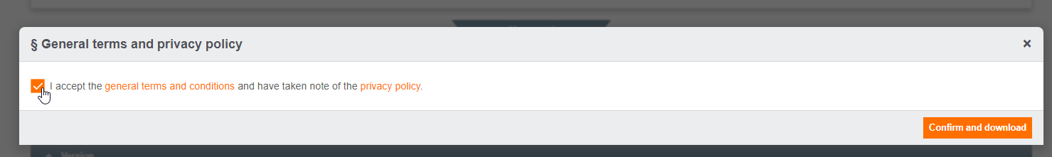
Agree to Policy and Download Tools.
Configuration Tools has been Downloaded.
Installation
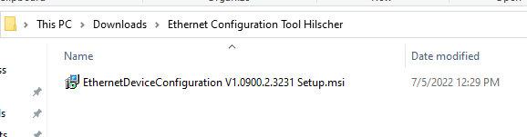
Unzip the ZIP and click on Setup.msi to install the tool.
Next.
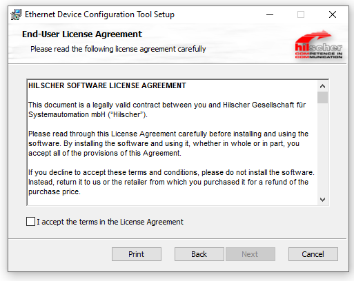
License Agreed and Next.
Install.
Wait for a while and it is ready!
Config IP
Set the IP Address of the IFM AL1320. Start the Ethernet Device Configuration Tools that you have just installed.
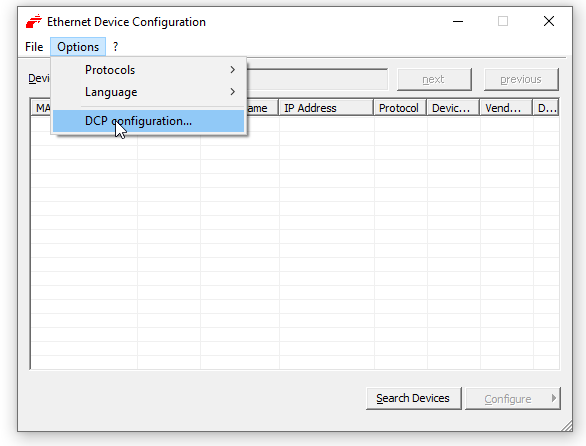
Ethernet Device Configuration Tools has been started.
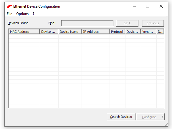
Click Options>DCP Configuration.
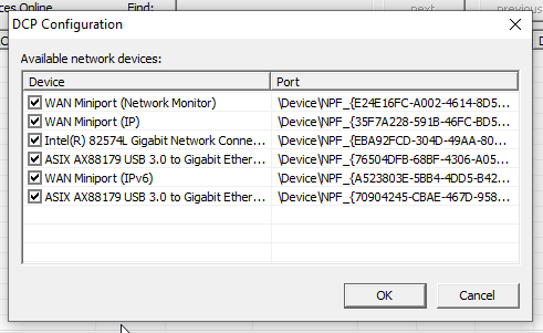
Select the Ethernet Interface connected to the AL1320 > OK.
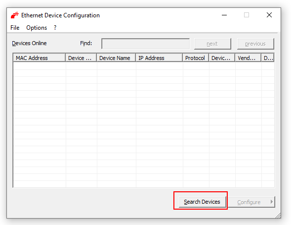
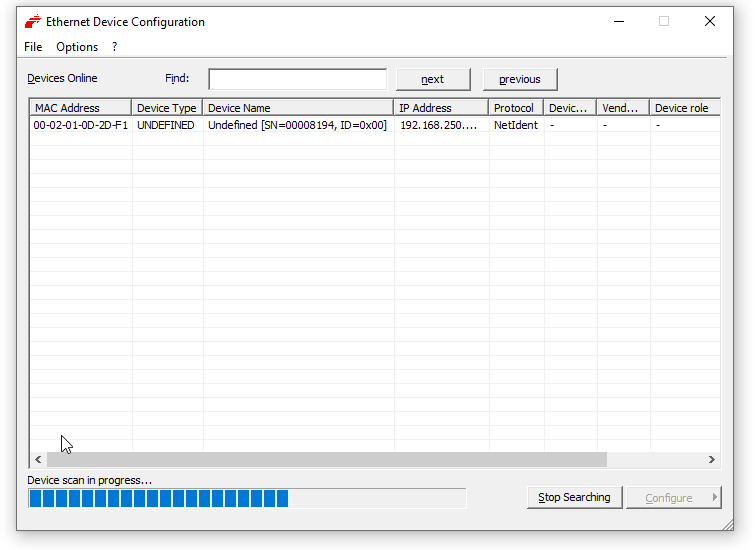
Click Search Devices to start scanning for devices.
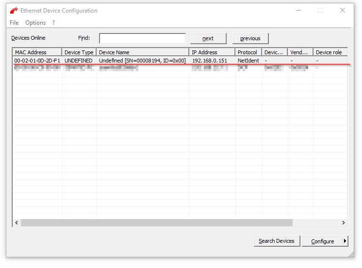
Found. The IP now is 192.168.0.151.
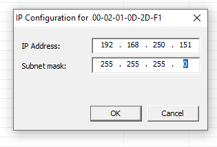
Right-click > Set IP Address.
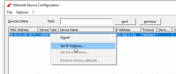
192.168.250.151 for this configuration.
Scan again to check if the IP has changed.
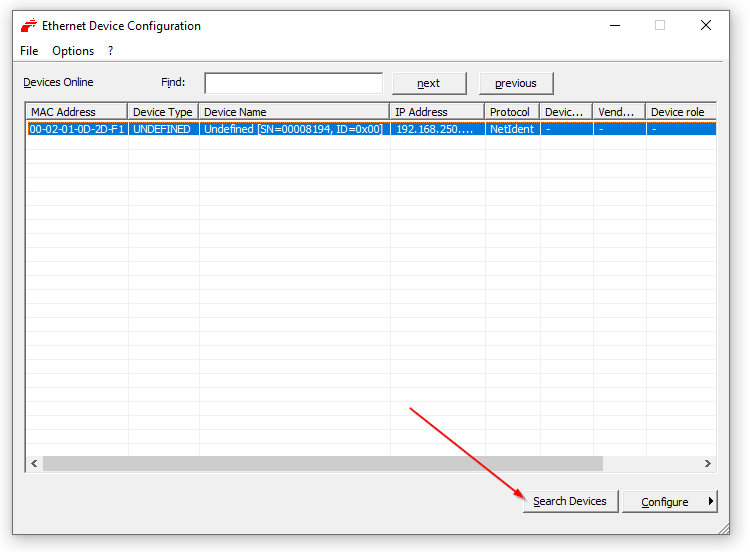
Good, there seems to be no problem.
Download EDS
Next, download the EDS File from the IFM HP.
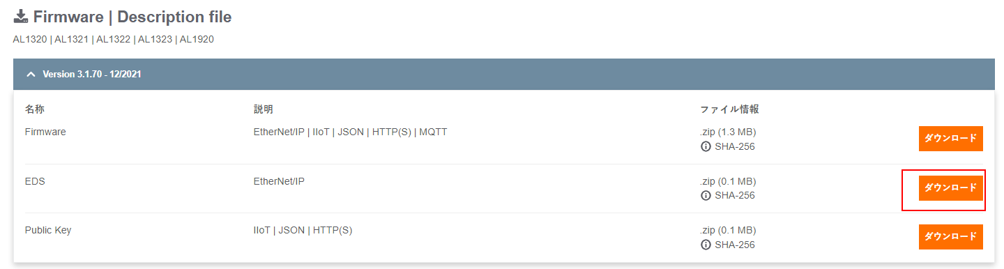
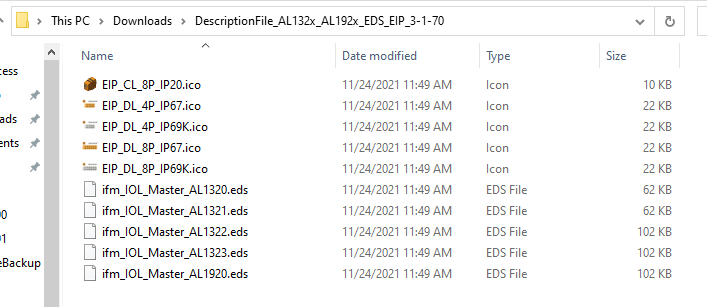
Just unzip the Downloaded File and you are good to go. These EDS Files are used on the Keyence side.
Keyence Side
IP Configuration
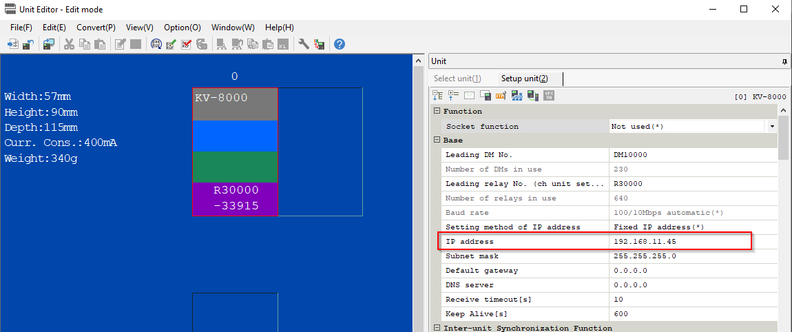
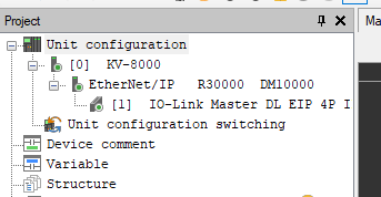
Set the IP address of the Keyence CPU: click Unit Configuration>KV-8000>Ethernet/IP.
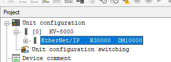
Set the IP address to 192.168.11.45 for this article.
Ethernet/IP Configuration
The next step is to configure the Ethernet/IP settings: right-click on the KV-8000>Ethernet/IP Setting.
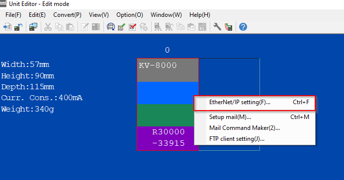
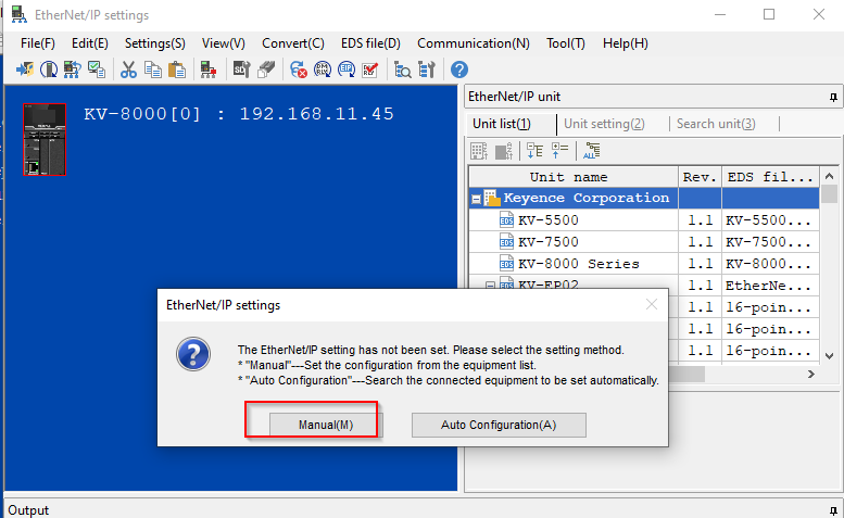
We will build the network manually, so proceed in Manual.
Install EDS File
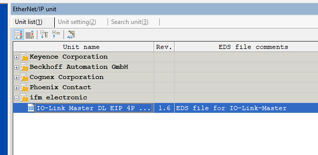
Register the EDS File from the Ethernet/IP Unit on the right by right-clicking>Register EDS File.
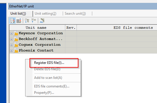
Select the EDS File you have just downloaded from the IFM HP and import it.
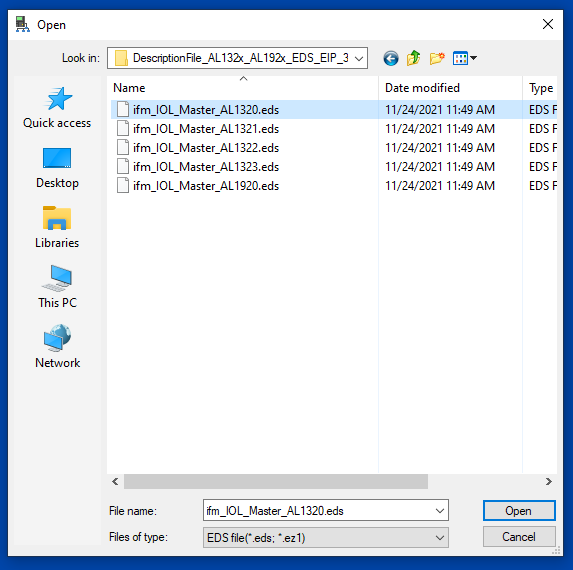
IO-LINK master AL1320 Registered.
Insert IFM AL1320
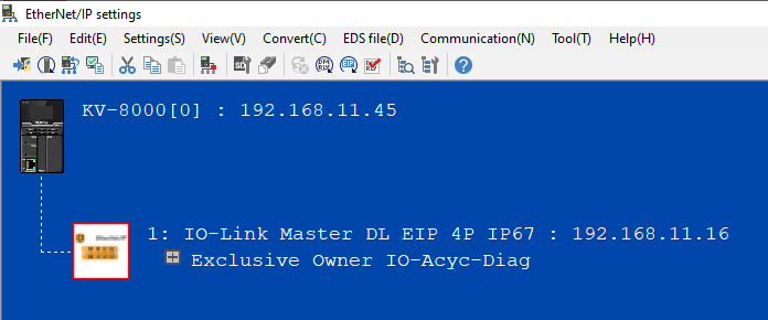
Select AL1320 and go straight to KV8000.
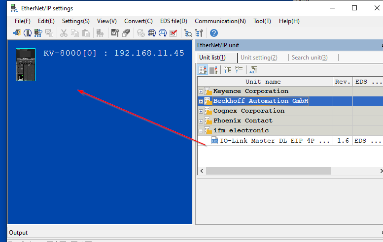
Done!The AL1320 Adapter has been added to the Ethernet/IP network.
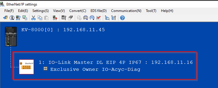
Configure the Adapter
Click Exclusive Ower on AL1320 to configure Adapter.
Setup Parameters
Basic parameters such as RPI can be set, as well as detailed settings such as each Port.Click Setup parameter.
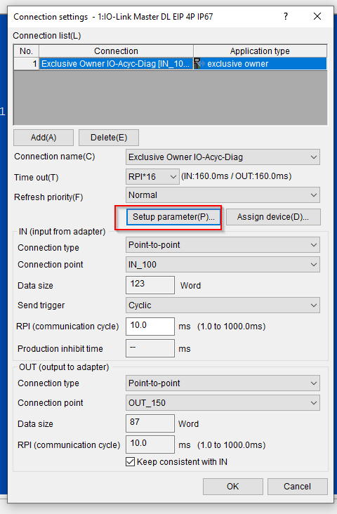
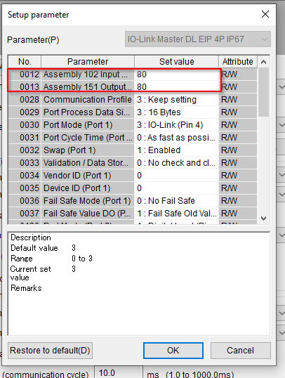
Assembly Input/Output Size(Bytes)
Fix the Input/Output data to 80 Bytes (40 Words) at 0012 and 0013.
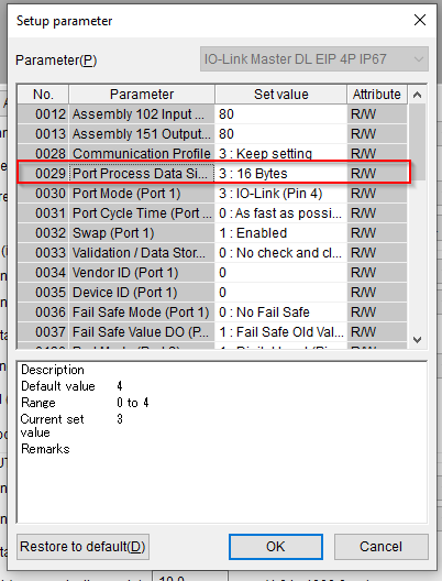
Port Process Data Size
At 0029, each Port occupies 16 Bytes.
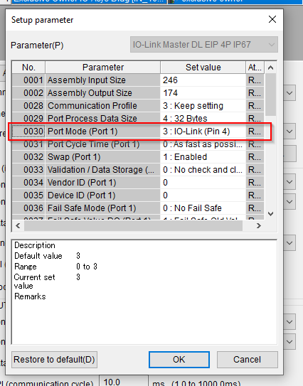
Port1
0030 to set Port Mode of Port1 to IO-Link.
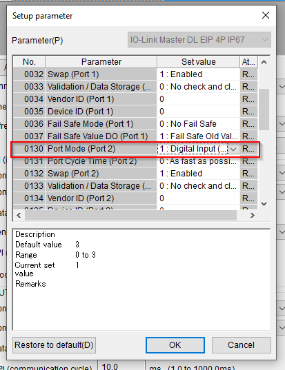
Port2
Set Port Mode of Port2 to I Digital Input at 0130.
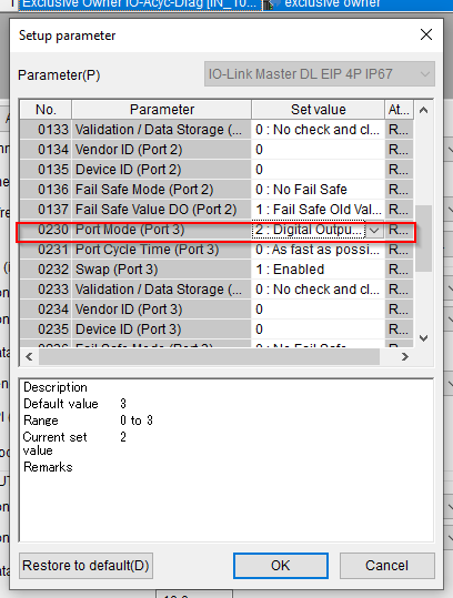
Port3
Set Port Mode of Port 3 to Digital Output at 230.
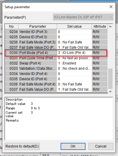
Port4
Set Port Mode of Port4 to IO-Link.
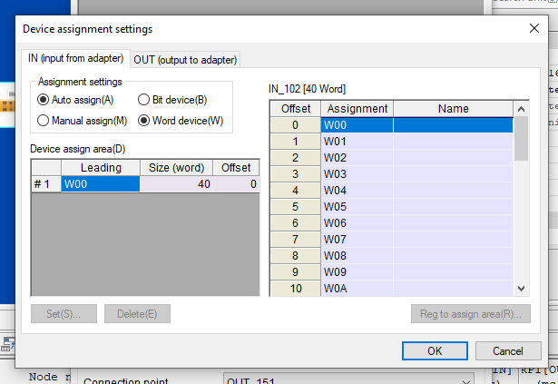
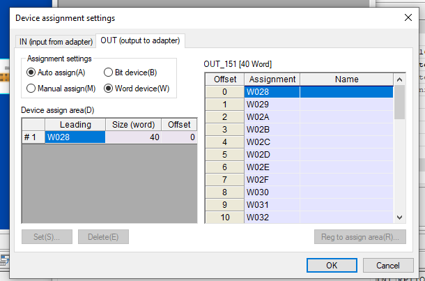
Assign Device
Assign Device sets the device allocation inside the CPU of the AL1320 Adapter.
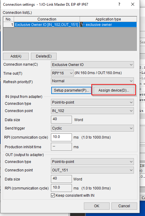
The input data is used from W00 , with 40Word.
The output data is used from W28 , with 40Word.
Program
The next step is to create a programme.
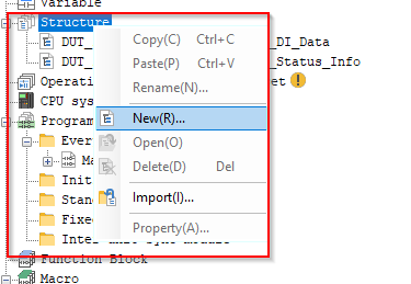
Structure
For keyence, a new structure can be created by Structure>Right-click>New.
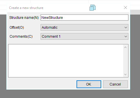
Enter the name of the structure in Structure Name>Ok.
You can then add variables in the structure.
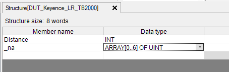
DUT_Keyence_LR_TB2000
This is a Keyence IOLINK distance sensor structure.
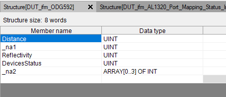
DUT_ifm_ODG592
This is the structure of IFM’s distance sensor ODG592.
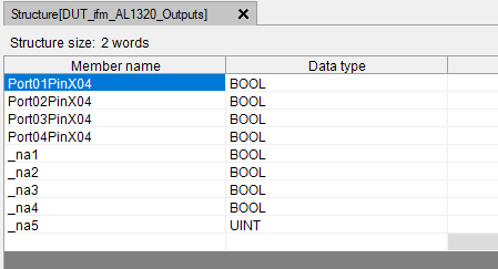
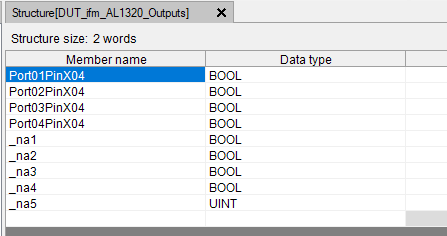
DUT_ifm_AL1320_Outputs
This is a structure that controls each Port output of IFM’s Ethernet/IP IO Link Master AL1320.
DUT_ifm_AL1320_Port_Mapping_DI_Data
This is the structure of each Port input of IFM’s Ethernet/IP IO Link Master AL1320.
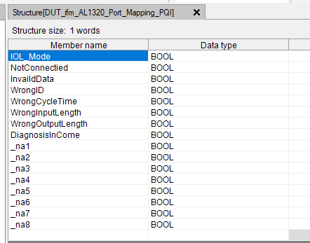
DUT_ifm_AL1320_Port_Mapping_PQI
This is the structure for each Port error information of IFM’s Ethernet/IP IO Link Master AL1320.
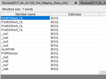
DUT_ifm_AL1320_Port_Mapping_Status_Info
This is also the structure for each Port error information of IFM’s Ethernet/IP IO Link Master AL1320.
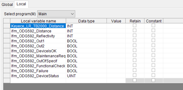
Variables
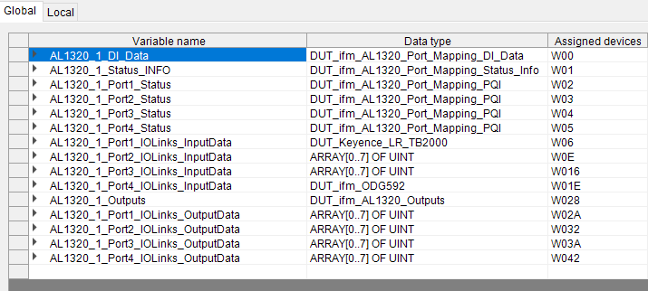
Once the structure definition is finished, the next step is to declare variables.
Global
Local
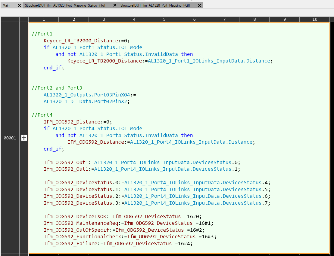
MAIN
The main program is used to acquire information from the IO LINK Sensor, determine error status, etc.
Download
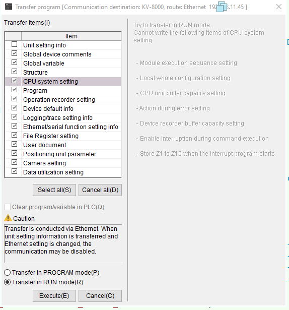
The last step is to Download the project to the CPU.
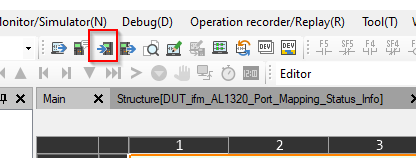
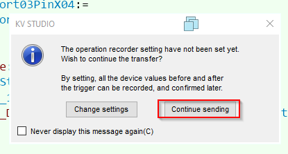
Continue sending to proceed.
Execute with Execute.
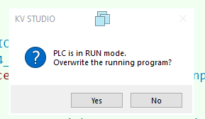
Yes。
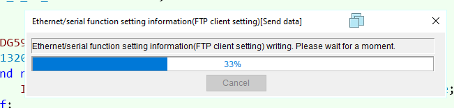
Just a second..
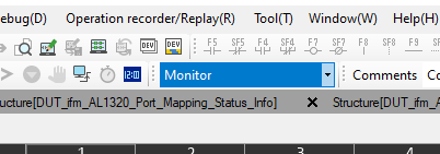
Monitor
Switch KV Studio to Monitor Mode and check the results.
Result
First of all, there is a small green ICON next to the IO-LINK Master, which indicates that it is already connected.
プログラムがしっかり動いていますね。
OK Status
https://youtube.com/shorts/GeklW__Kf3E
Error Status
https://youtube.com/shorts/TXKTt9z3CyE
Operation
Soruce Project
You can download the project from this Link.
https://github.com/soup01Threes/Keyence/blob/main/IFM_ConnectionTest.kpz