In this article I will show you a new Factory Automation from CDP Studio, created by CDP Technologies, a software company from Norway. CDP Studio’s FB is based on IEC61499.
Let’s get started!
Reference Link
CDP Studio?
CDP Technologies is a Norwegian independent software company whose primary goal has always been to simplify control system development and enable any company to create the next generation of industrial solutions.
With this in mind, they developed the Control Design Platform (CDP) and these products, CDP Studio, is a field-proven, state-of-the-art low-code software platform. This tool is based on IEC61499 and is one of the best solutions for distributed control from now on.
Of course, not all the features can be identified in that article alone, so you can refer to CDP’s website for more detailed information.
Who can use?
Who should use CDP Studio?
Software Developer
CDP Studio provides a platform for writing code in C++, integrating Python, Java, and JavaScript, running applications on IPC, Linux controllers, and industrial RPi, and integrating industrial IO and sensors. CDP Studio allows you to create your own functionality freely code, integrate open source and third-party libraries, and use a wide variety of hardware. The future is truly an open and flexible system with no vendor restrictions.
Automation Engineer
For automation engineers who are familiar with ladder and graphical PLC programming, CDP Studio is a tool for you to quickly become accustomed to. CDP Studio has a low-code, graphical programming mode similar to graphical PLC programming.
COMPATIBILITY
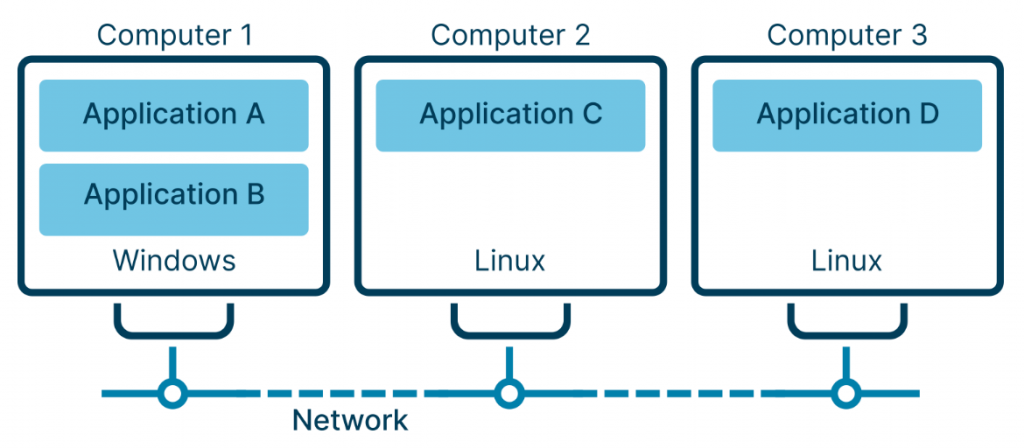
CDP Studio is independent of hardware vendor and device type. It can operate systems in a multi-vendor environment combining IPCs, industrial controllers, and routers, allowing applications and functions to be distributed across multiple controllers, independent of hardware type or operating system.
It then decouples application logic from specific hardware dependencies. The control system can be easily ported to a new hardware platform, even if the hardware is from a different vendor. This allows the control system to adapt and expand as your needs and external technological developments change.
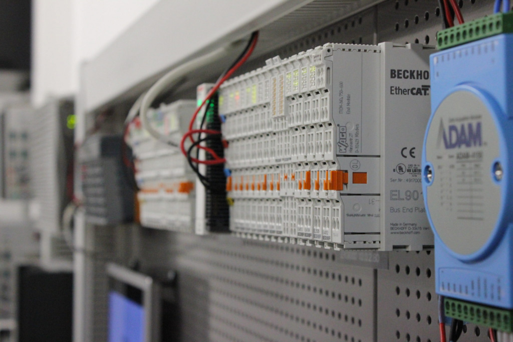
I/O MODULES
CDP Studio has built-in support for IO modules from a variety of industrial I/O vendors.And you can of course create your own hardware support or add your own preconfiguration.
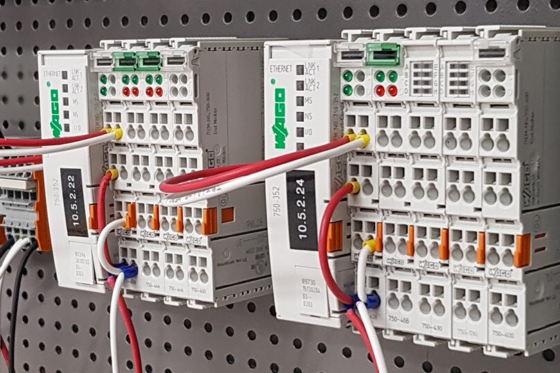
Hardware that can be supported:(from CDP Studio’s HP)
- Wago
- Phoenix Contact
- Weidmuller
- Beckhoff
- B&R
- Insys icom
- Revolution Pi
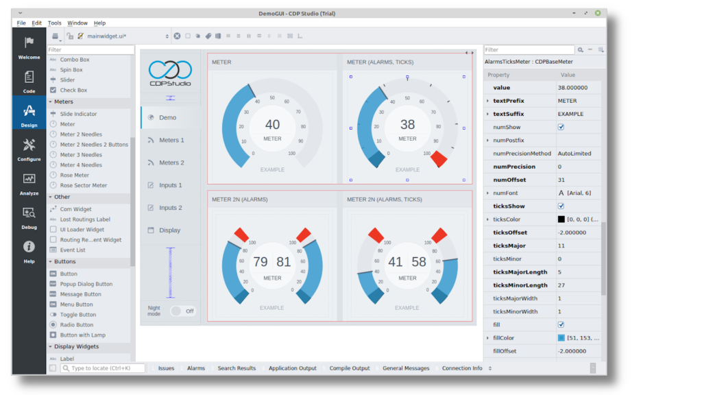
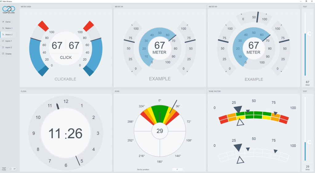
CDP Studio UI Designer
CDP Studio UI designer allows engineers to create screens that can be easily manipulated with drag and drop. The CDP Studio UI designer is fully integrated into the IDE, making it easy to connect to the signals, parameters, and properties needed for UI screens. signals, parameters, and properties needed for UI screens.
No-code Web HMI!
You can also easily create web HMIs using CDP Studio UI Designer with no coding required. You can create excellent web HMIs from a drag-and-drop editor without the knowledge of html5 or other languages.
develop
The CDP Framework provides reusable libraries and functions. The framework ensures high-performance execution of real-time and distributed systems and includes a variety of functions such as API, Protocol, State Machine, Signal Processing, Event Processing, Messaging, and Parameterization.
One System,More Application
A control system in CDP Studio consists of one or more applications. You can create separate applications dedicated to specific tasks, which together constitute a complete control system; you can separate the HMI and the control program into separate applications. Applications can contain functional blocks that execute with different HZs and priorities, run on the same controller or on separate controllers independent of operating system or hardware type.
TOOLBOX
The CDP Framework includes a comprehensive set of features used in control and automation. The toolbox currently supports the following protocols
- OPC UA
- MQTT
- Modbus
- CANopen
- SNMP
- NMEA
- UDP
- GPIO
- I2C
Of course, you can also develop and add your own protocols.
Download
Download CDP Studio from the link below.
https://cdpstudio.com/download/
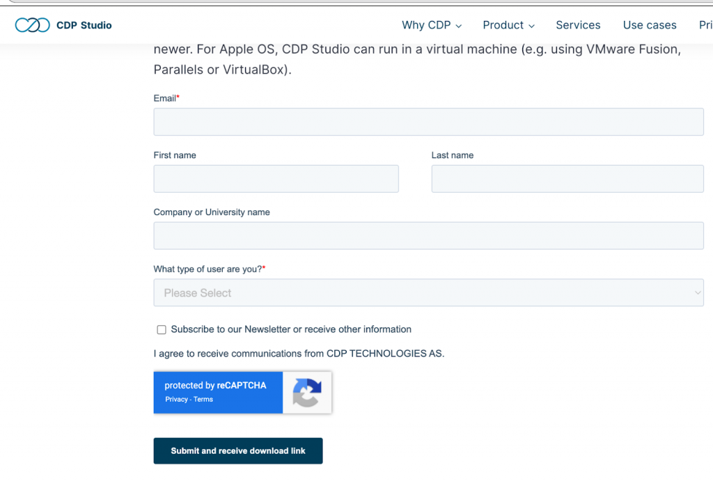
After entering your personal information, you can download the software.
Windows and Linux versions are available, but I recommend Linux. (I wrote this article in the Linux version.)
Installation
Copy the Linux Version Setup File downloaded from your PC to VMware.
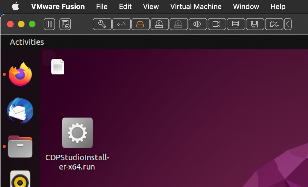
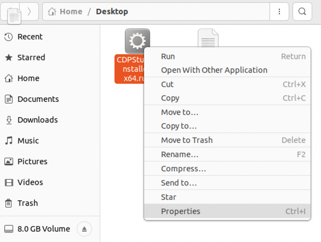
Right click>Properties.
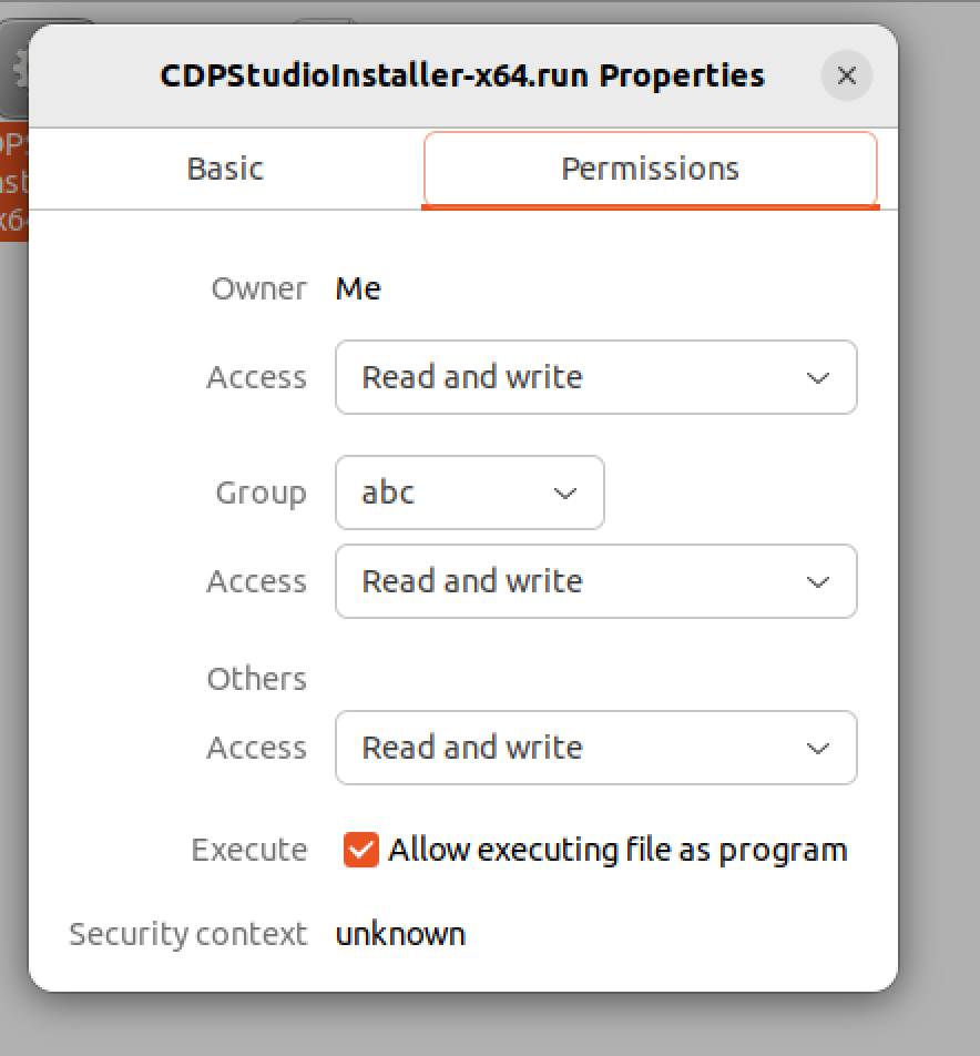
Put the CheckBox for Execute in the Permissions section.
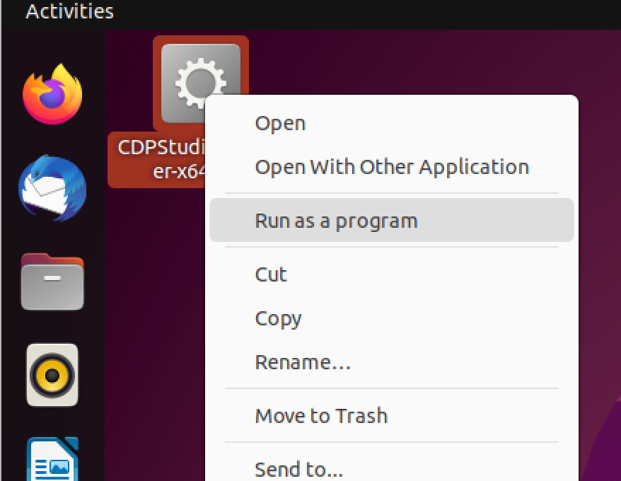
Next, right click>Run as a program.
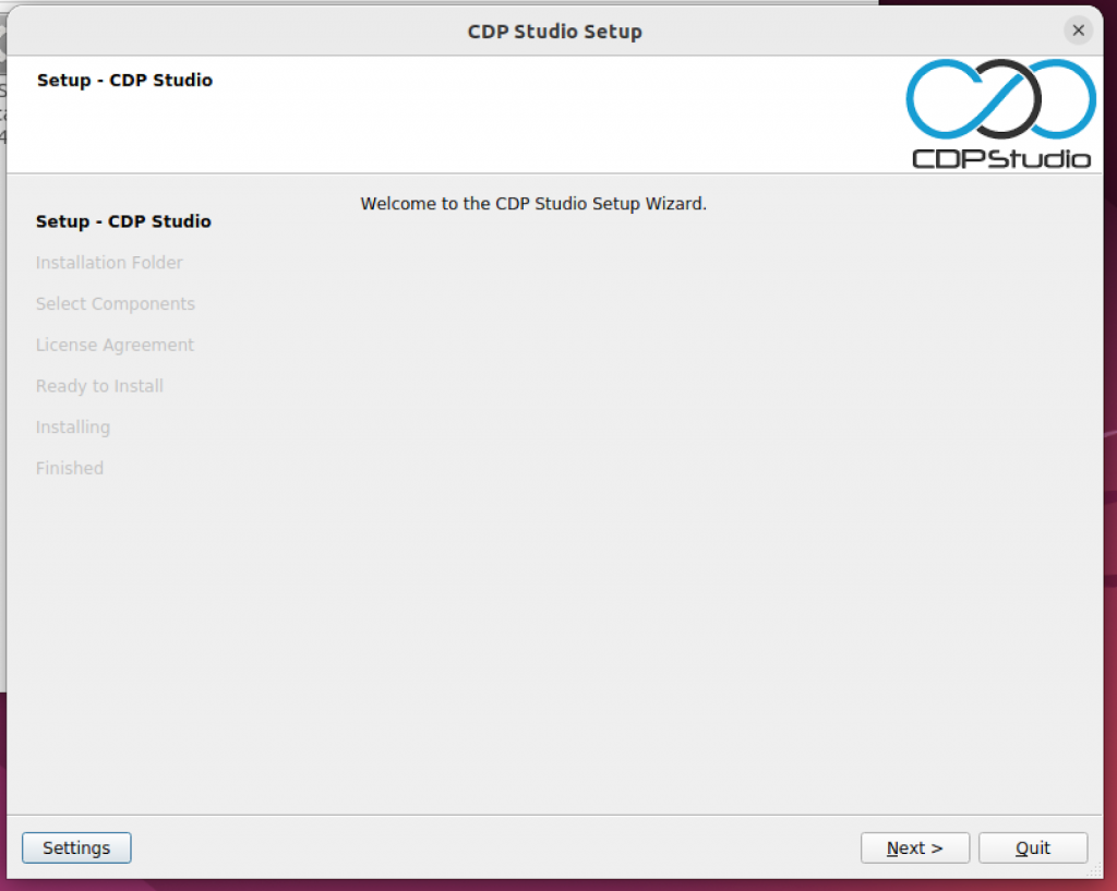
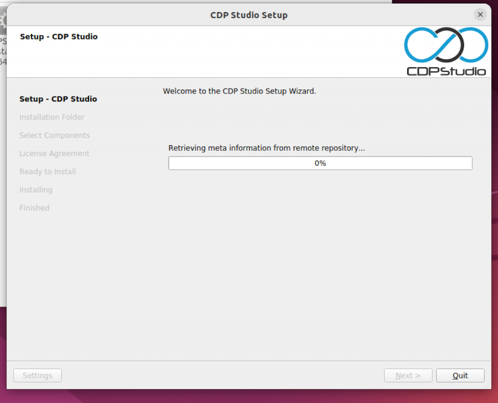
Next>.
just a second..
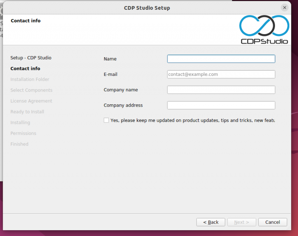
Enter your information and Next>.
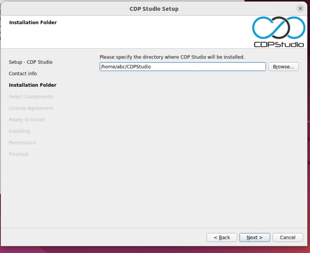
Configure your installation Path and Next>.
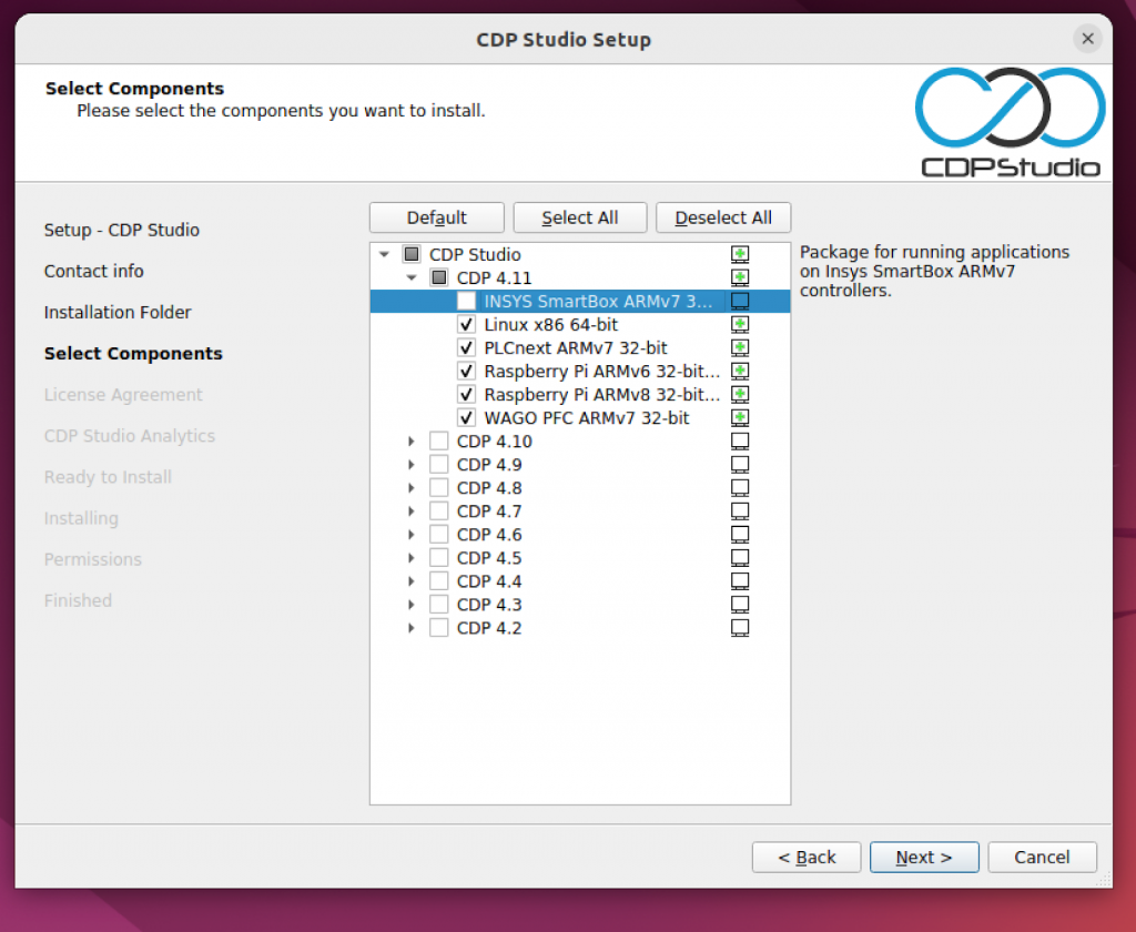
Now you can select which components that would like to install inside your pc.
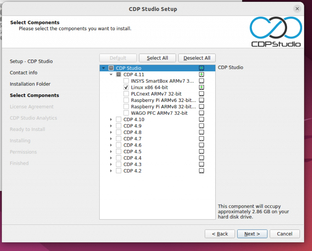
Put the Checkboxes for all parts in the latest 4.11 and proceed with Next>.
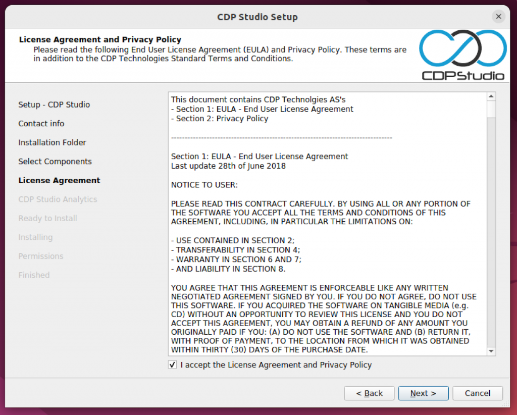
Agree the license and Next>.
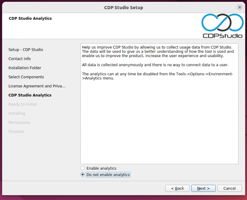
Next>.
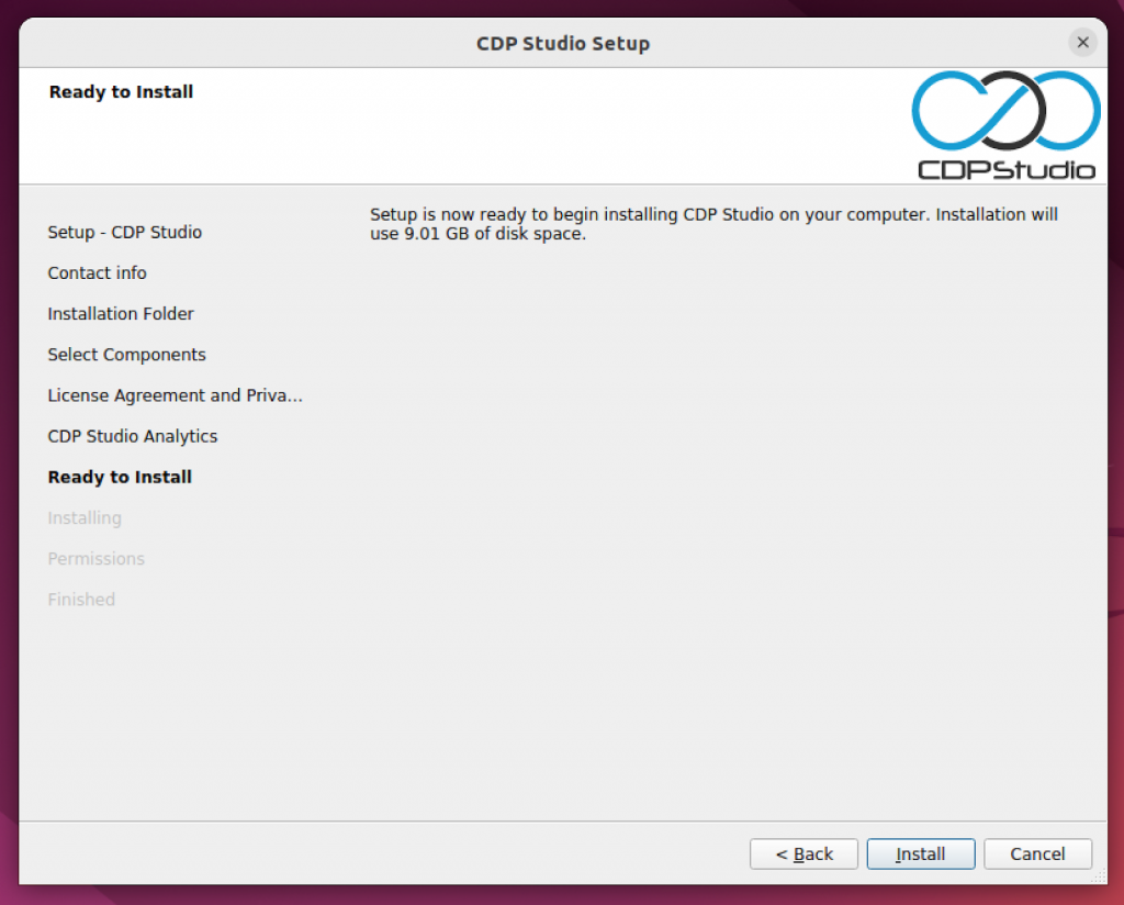
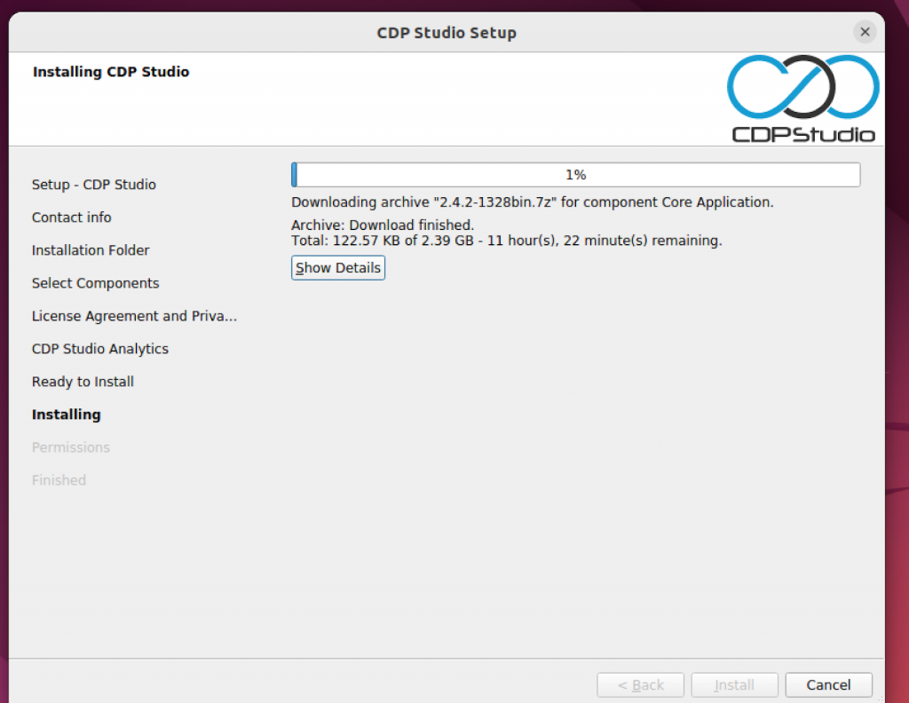
Install it!
just a second..
Done!Press Next> to continue.
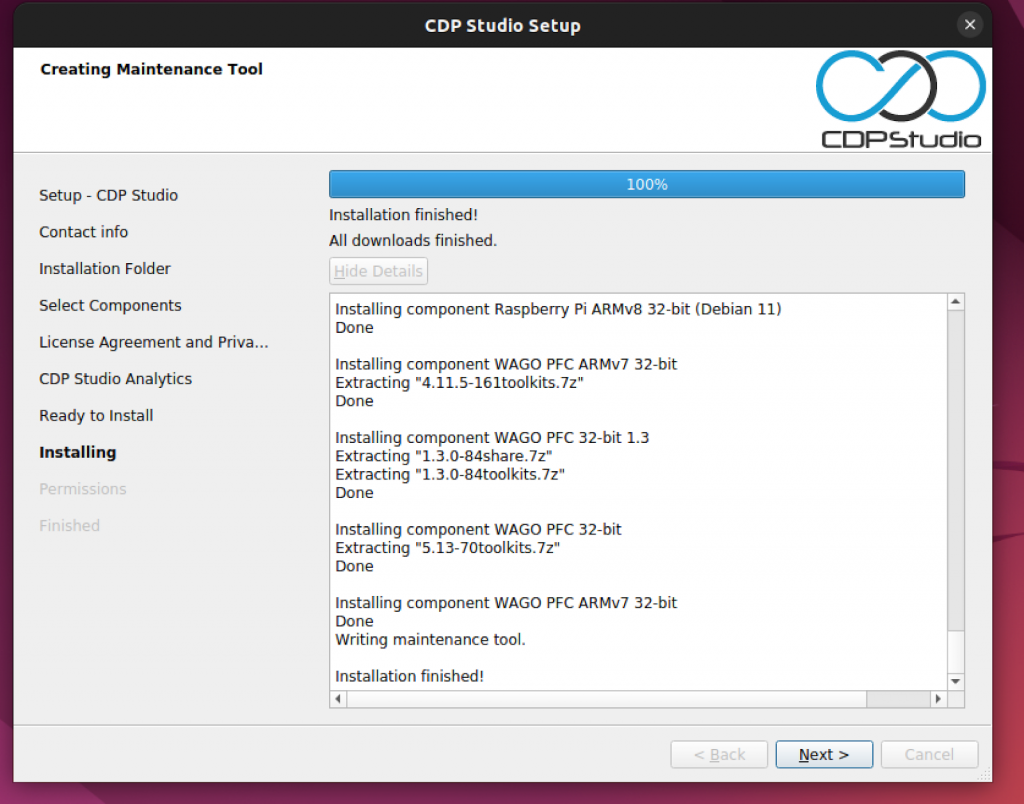
Next>.
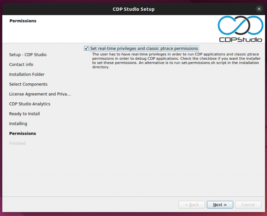
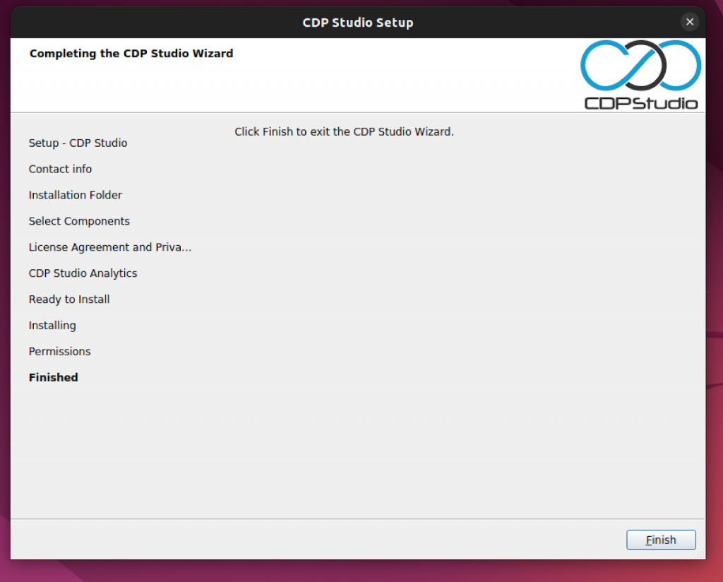
Done!
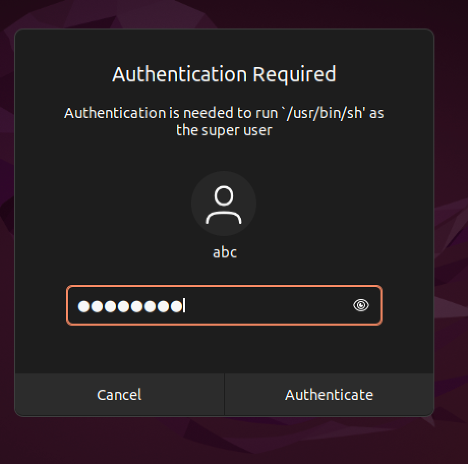
You will be prompted for User password, enter your Password. This is the end of the process.
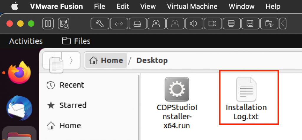
If there are any problems with the installation, please check this file.
Start
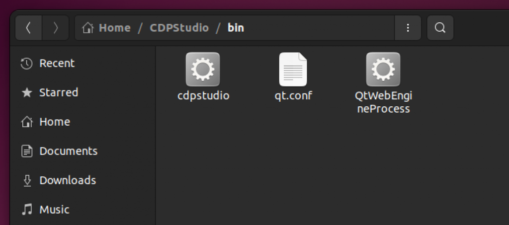
The installation data should be stored in Home/CDPStudio/bin.
Run “cdpstudio”.
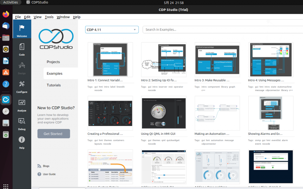
Done! CDP Studio has been started.
New Project
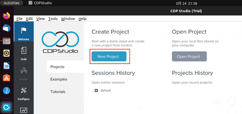
Create a new project at Welcome>New Project.
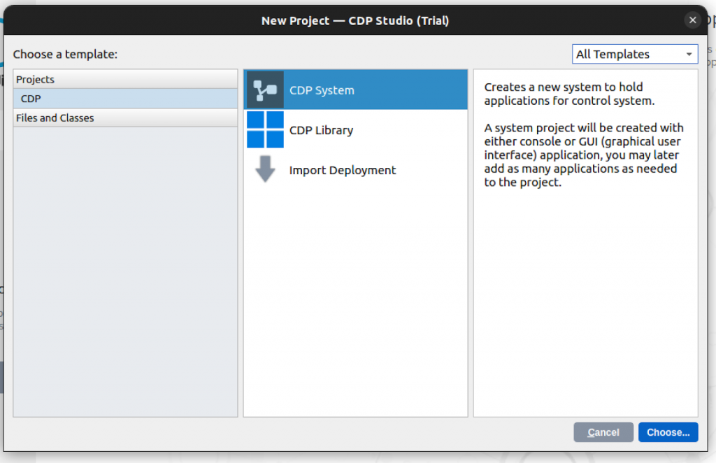
Since this is the first episode, we do not intend to do anything complicated, so we select CDP System and proceed with >Choose.
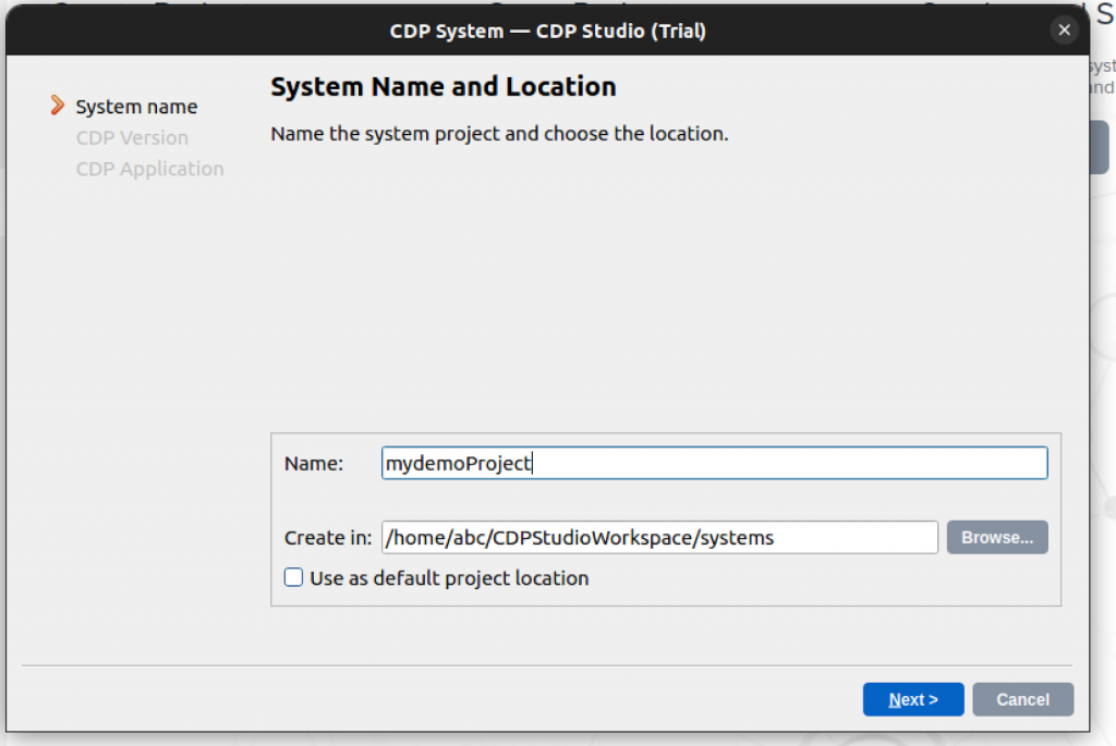
Enter the project and press Next> to proceed.
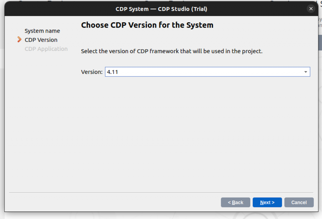
Multiple versions can coexist, but for this article, only the latest 4.11 is included, so we will use 4.11 and Next>.
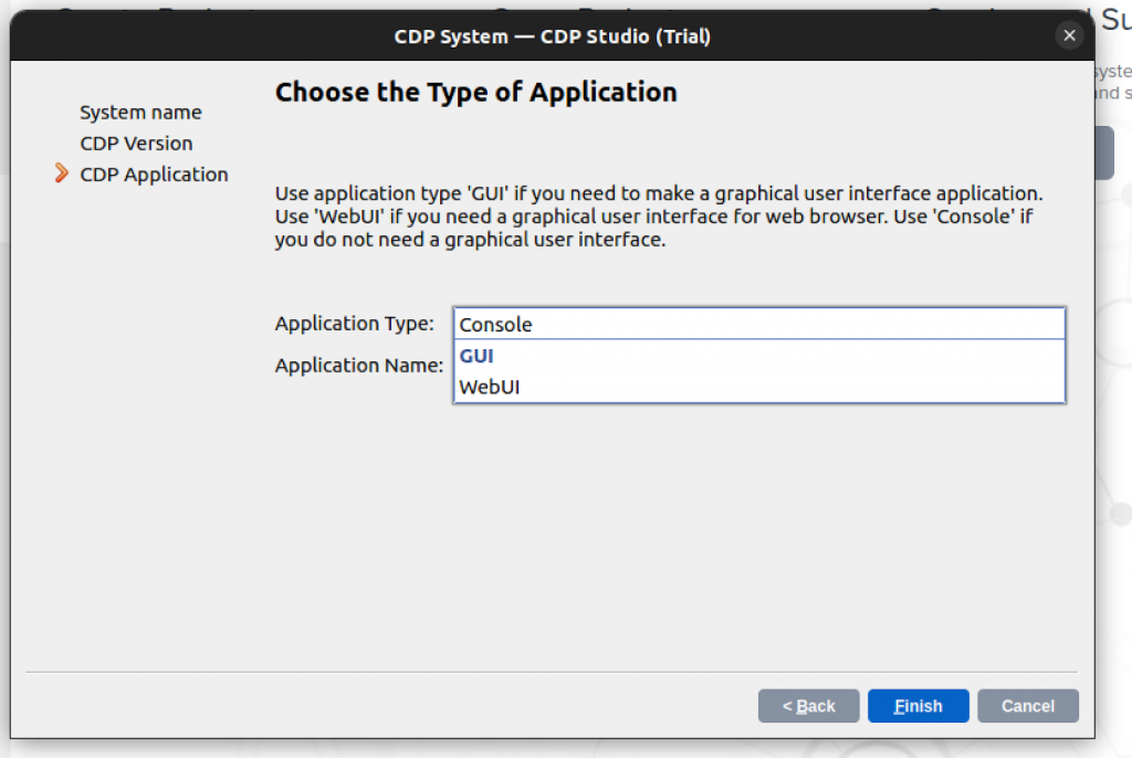
The Application Type selection screen will appear.
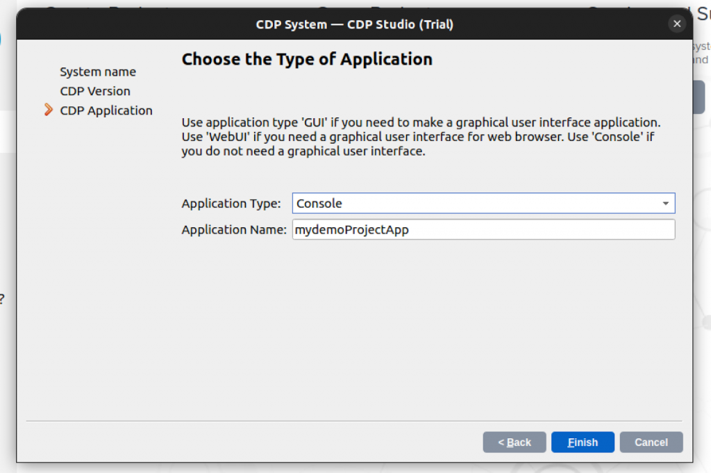
Console, GUI, and WebUI can be selected for the Application Type, and this time the Console project will be used.
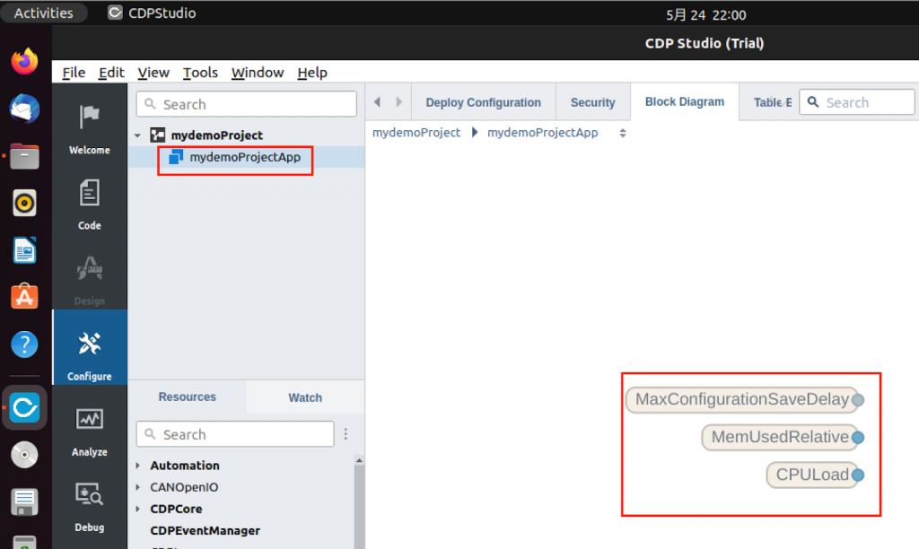
Done! A new project has been created.
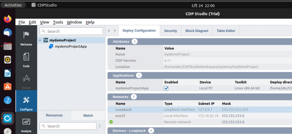
If you open Configure>mydemoProjectApp, you will see the data (CPU load, memory load, etc.) generated by Project Default.
Sequencer?
Sequencer is an AddON developed by CDP Studio that allows the development of sequential control tasks, such as control and step control tasks that have been commonly used in FA production lines.
Sequencer’s default behavior is derived from the event-based control standard defined in IEC 61499. With its modern open architecture, Sequencer allows developers to build distributed software blocks that can be used standalone or as part of a larger system.
In other words, Sequencer should be understood as a modeling language similar to the traditional IEC61131-3 Function Block. The language also separates the control flow from the data flow in a straightforward manner, making it easier to design and understand.
Types of Sequencer Blocks
Sequencer Basic Block allows you to create new sequencer blocks with no code. The technique can also be used to build cyclic state machines using control branch basic blocks and conditional execution.
IEC 61499 defines three types of blocks that can be used when developing applications.
- Basic Function Block(BFB)
- BFB allows you to define a state machine using an Execution Control Chart (ECC), which determines which operations to perform based on its state and input events.
- Composite Function Block (CFB)
- It is a set of multiple BFBs and SFBs.
- Service Function Block(SFB)
- SFBs are sequencer blocks that can be used to implement access to specific hardware, services, and protocols in C++.
Sequencer Block Interface
The Sequencer Block encapsulates an existing CDP Operator (i.e., CDP Studio’s own Block) for data processing.
As with traditional blocks, inputs are on the left and outputs on the right, but the interface distinguishes between Events and Data; the red arrows at the top of the block indicate Event input and output, and the blue areas at the bottom indicate Data input and output.
Components
Now we will describe each component of Sequencer.
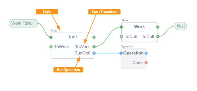
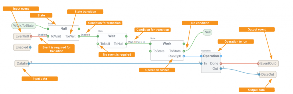
StateTransition
A State block State Block in the Basic Block Execution Control Chart (ECC) can have a StateTransition to another state.
A StateTransition, i.e., a transition to another state, must be triggered from an inputEvent. In this case, the EventIn input is connected to the StateTransition.
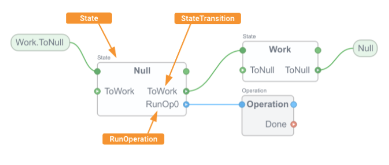
Sequencer – State
Basic Block Execution Control Chart ECC) consists of a State Block that can have transitions to other states. As mentioned earlier, transitions require a True trigger of an input event.
Sequencer-EventIn
EventIn is the parameter through which the Basic Block receives events; when EventIn receives a message or event, the Data input is updated at the same time.
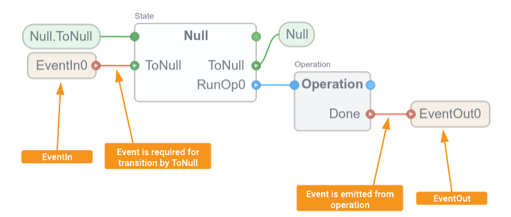
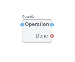
Sequencer-Operation
You can think of Operation as a box with a Done output, and the Done output is sent to Message each time when the Block completes processing.
Sequencer – EventOut
The EventOut is used by the Basic Block to send Event Messages; each time the EventOut sends an Event Message, the Data output is updated together.

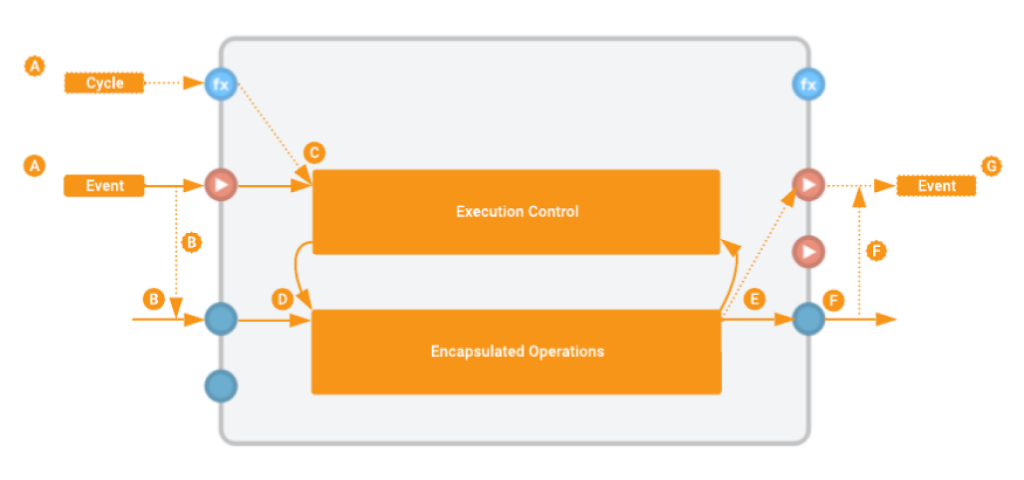
Internal Sequence
The following is the sequence of events from the time the Sequencer block is triggered until the function is executed.
When a block triggers either Cycle (A) or Event (A), the Data Input is updated (B), the state transitions (C) and internal logic is executed (D). Finally, the Event is output (E→G) and Data is also output (F) to complete the process.
Execution Control Chart (ECC)
The behavior of the block is controlled by the states that make up the Execution Control Chart (ECC). Transitions between states determine whether input events and transition conditions are Ture.
Basic Block is processed when an input Event is received in Default. Sequencer Input Events are consumed when they are needed for transitions, and only one such transition can be triggered during process execution.
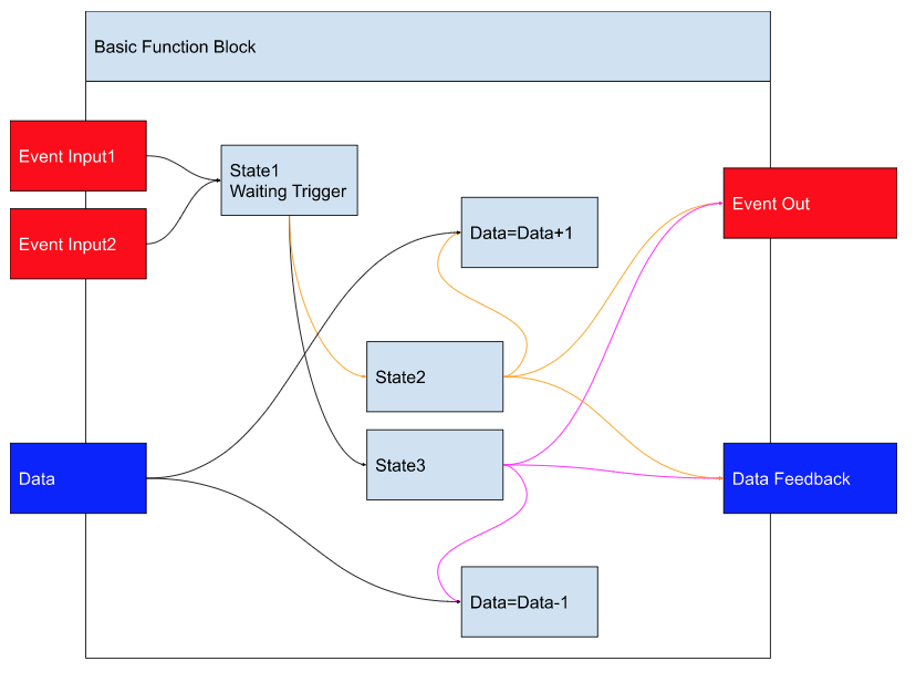
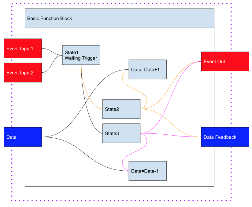
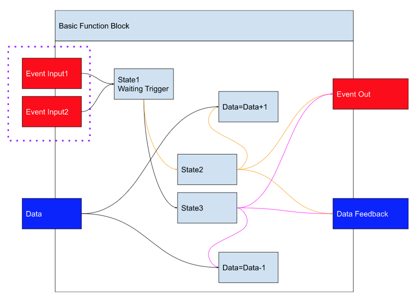
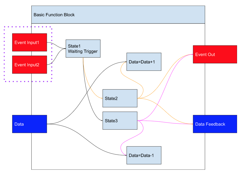
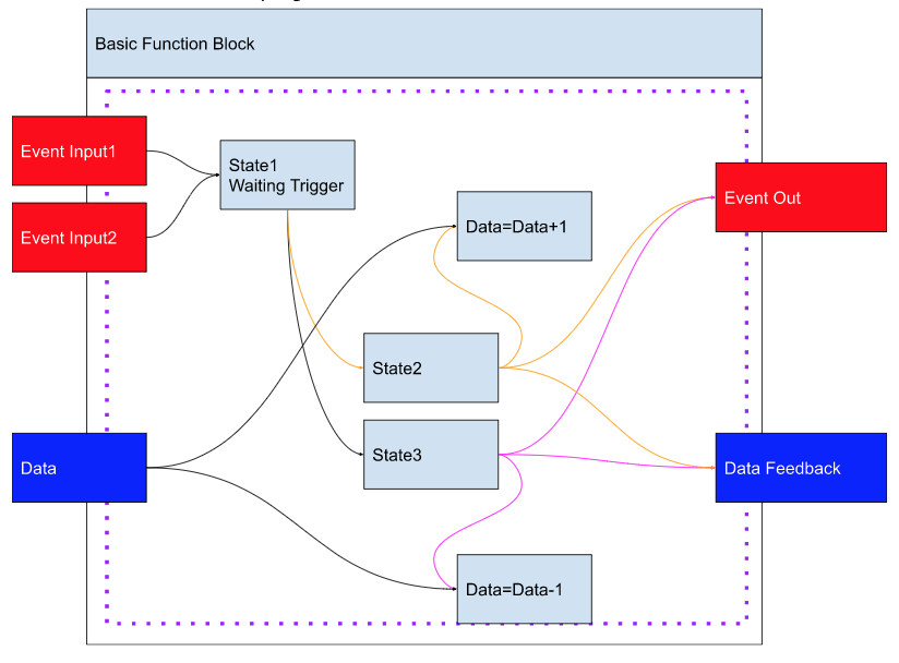
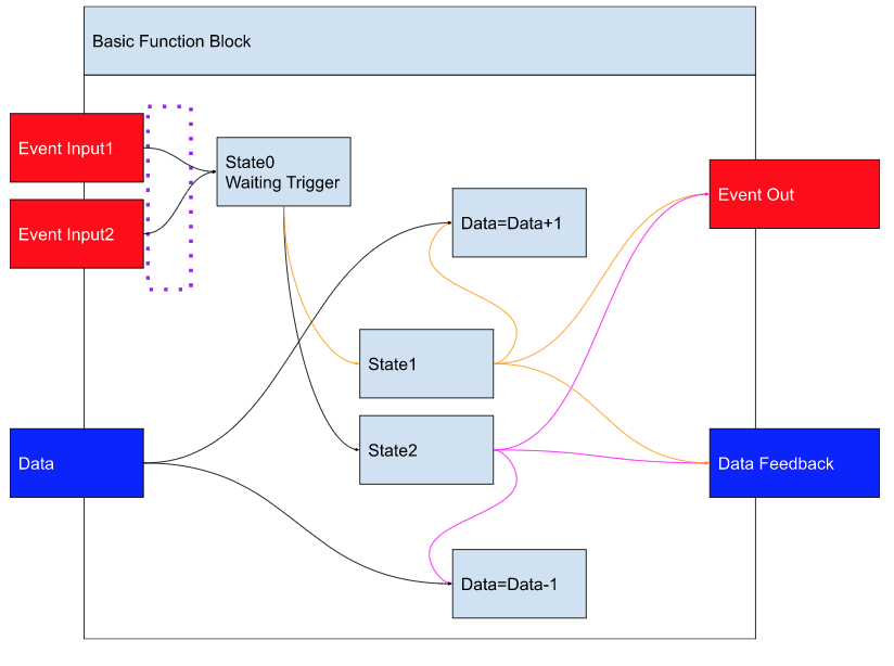
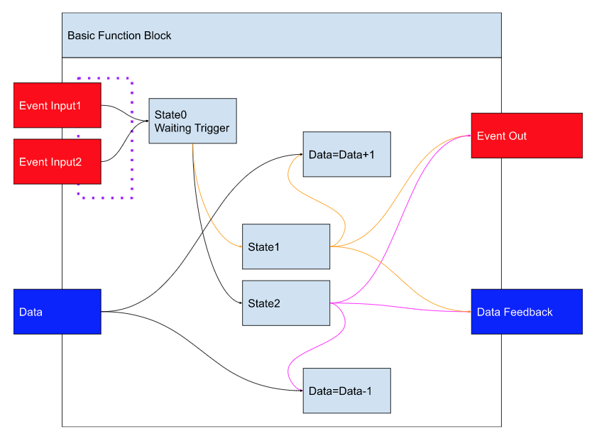
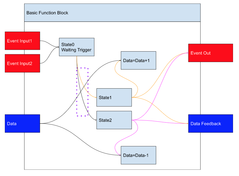
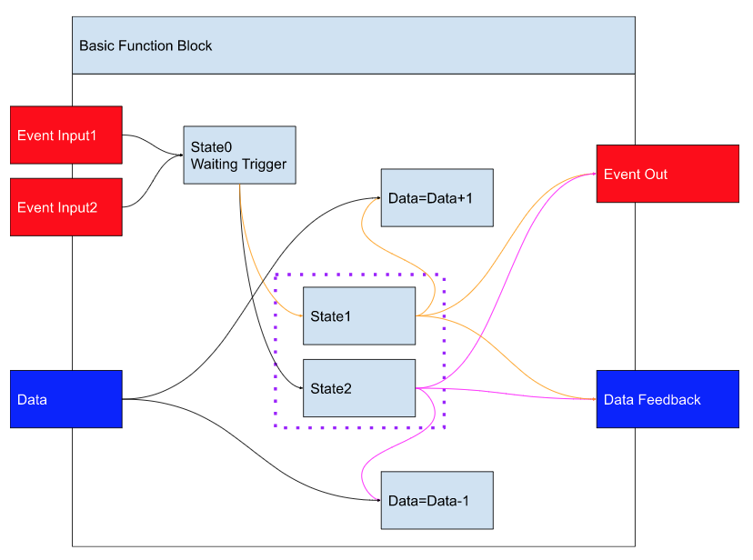
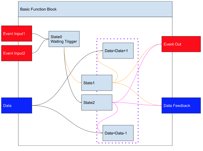
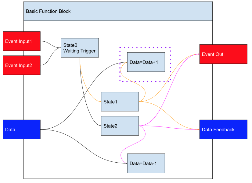
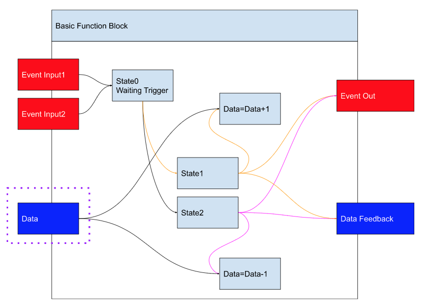
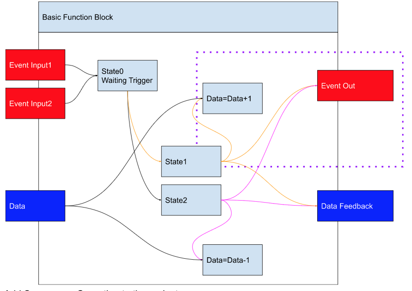
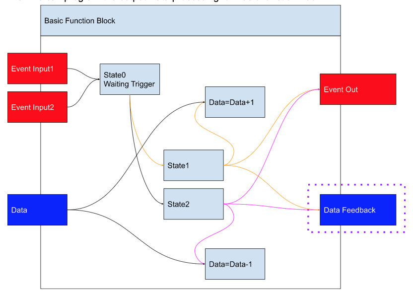
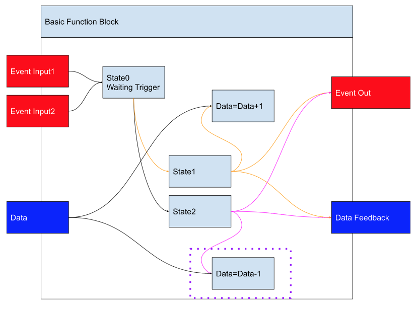
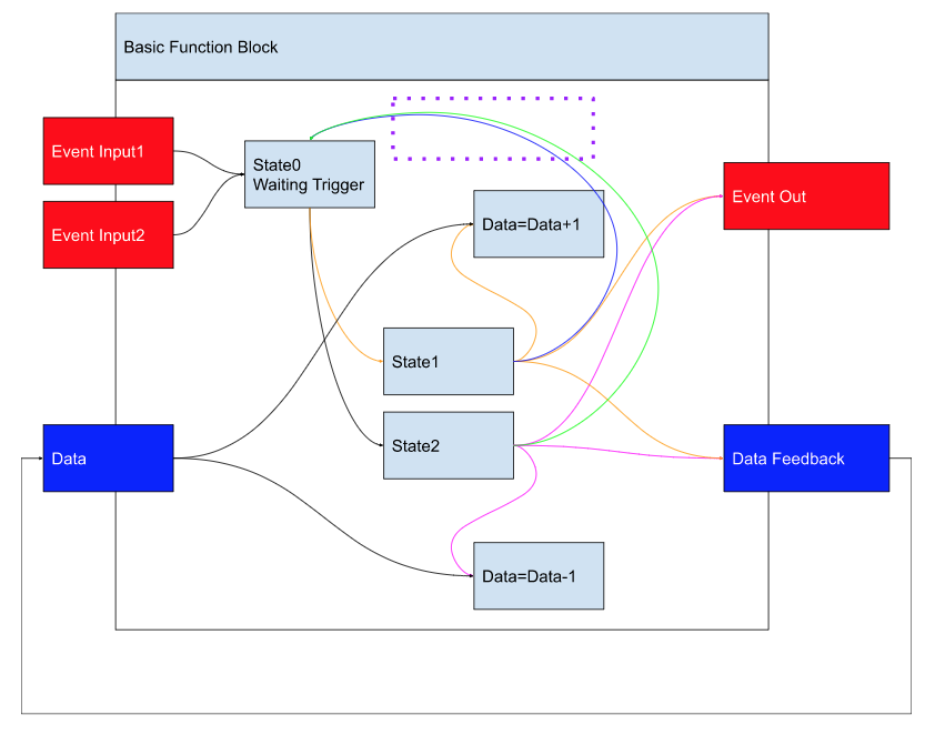
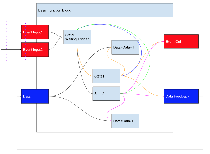
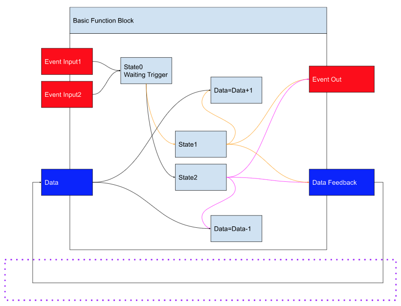
Flow
Here is the Flow diagram of the project we will implement in this tutorial.
Program it!
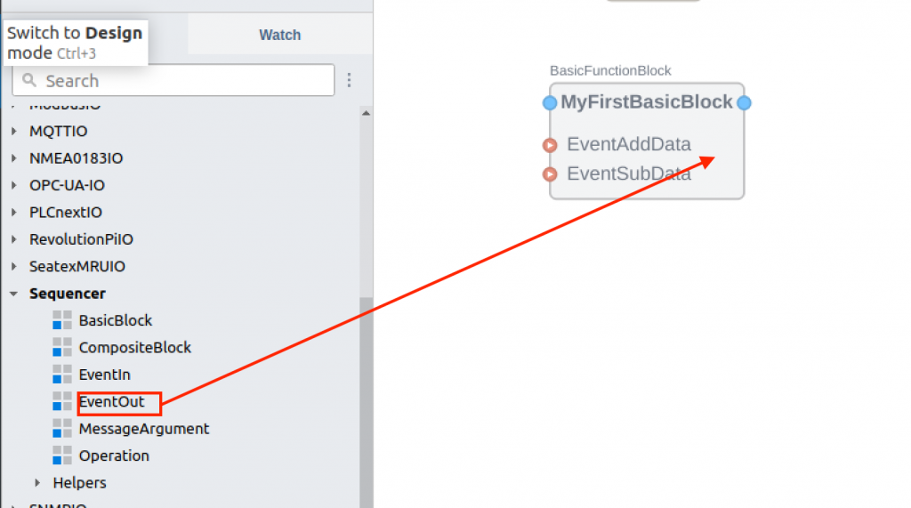
Add Basic Function Block
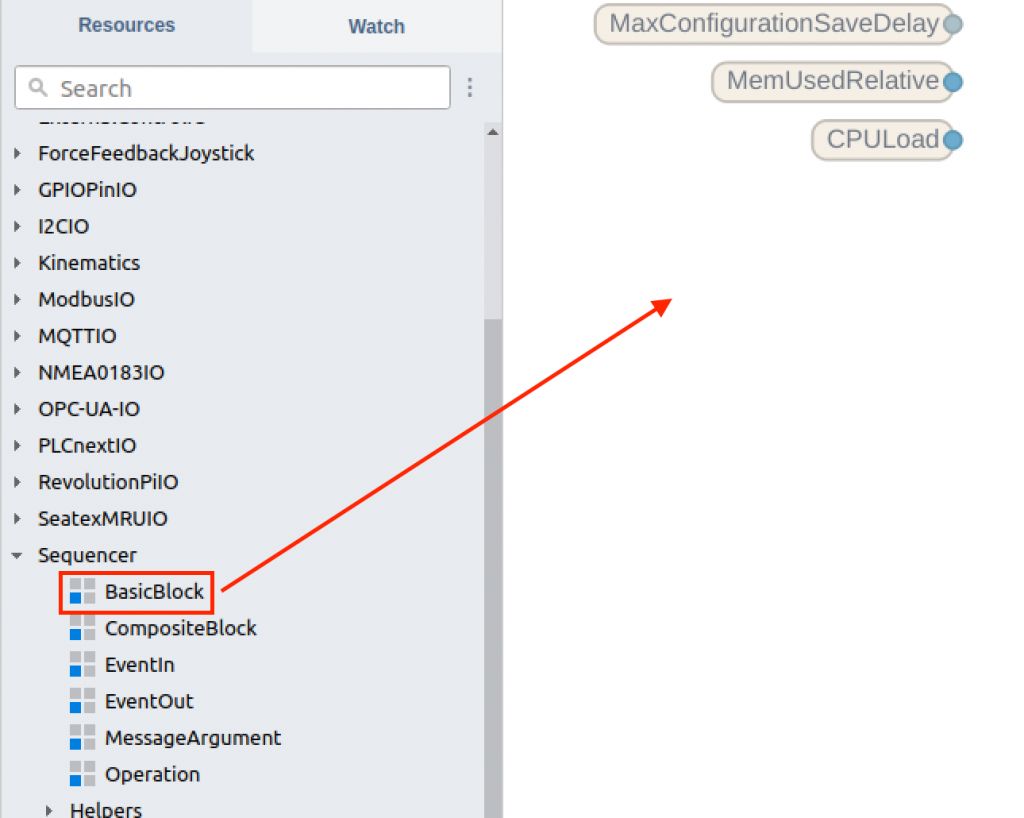
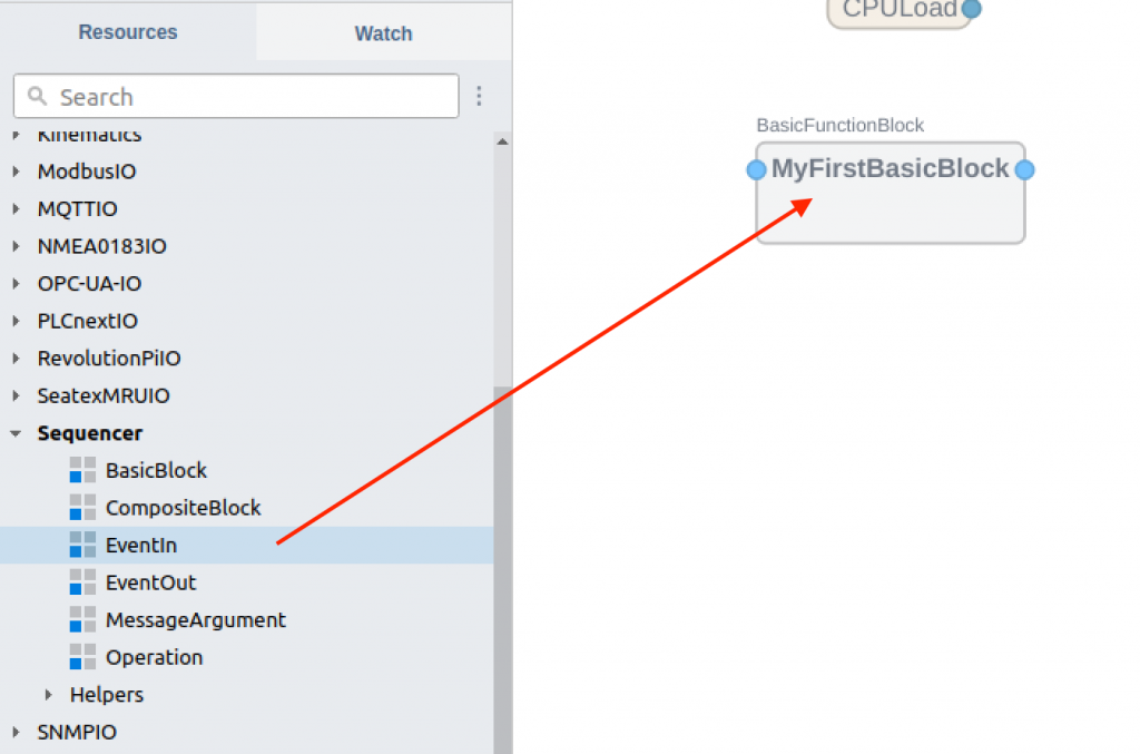
First, add a Basic Function Block in Flow.
You can select the Sequencer component from Sequencer from Resources on the right.
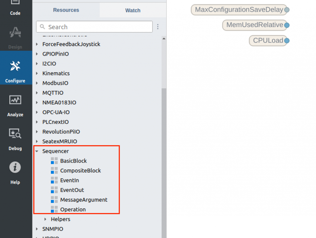
Add Basic Block to your project.
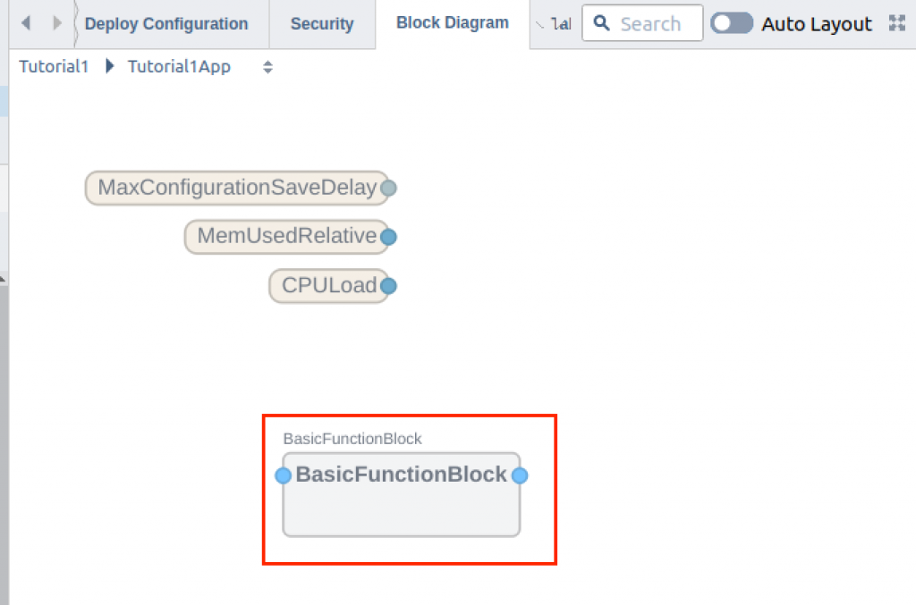
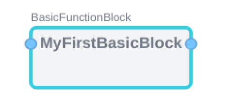
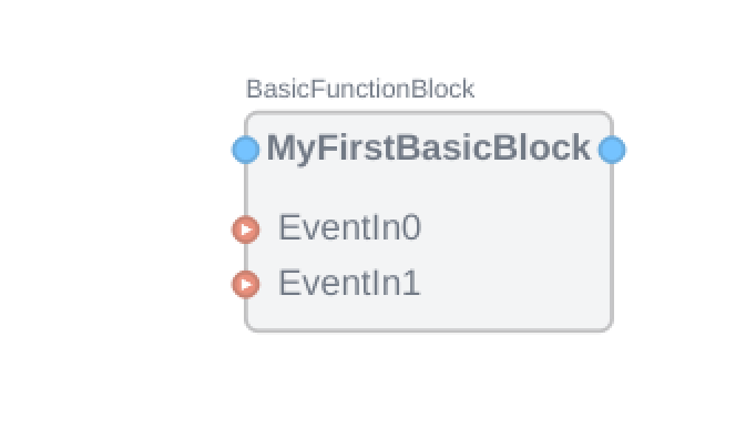
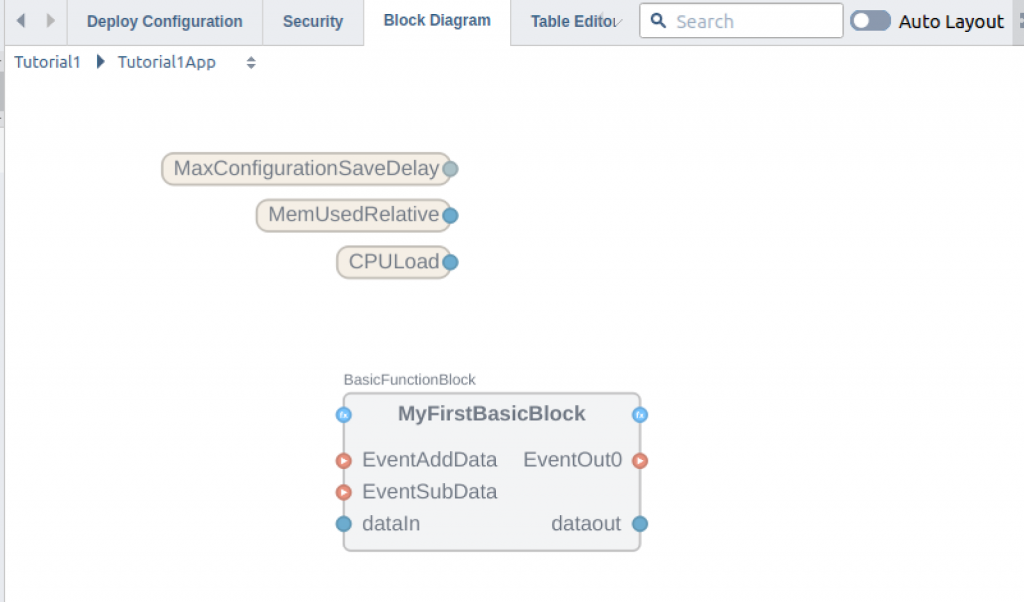
BasicFunctionBlock has been added.
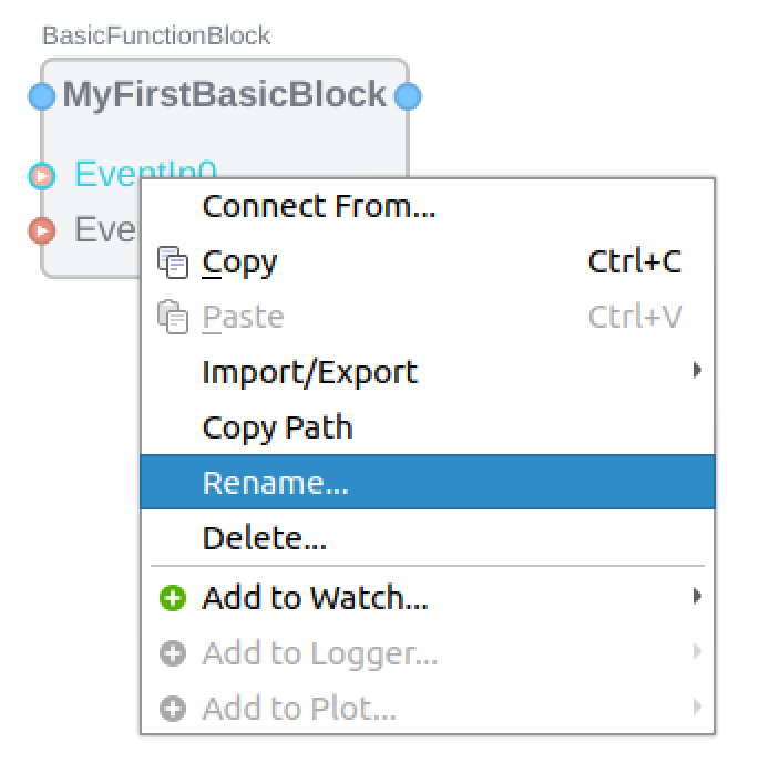
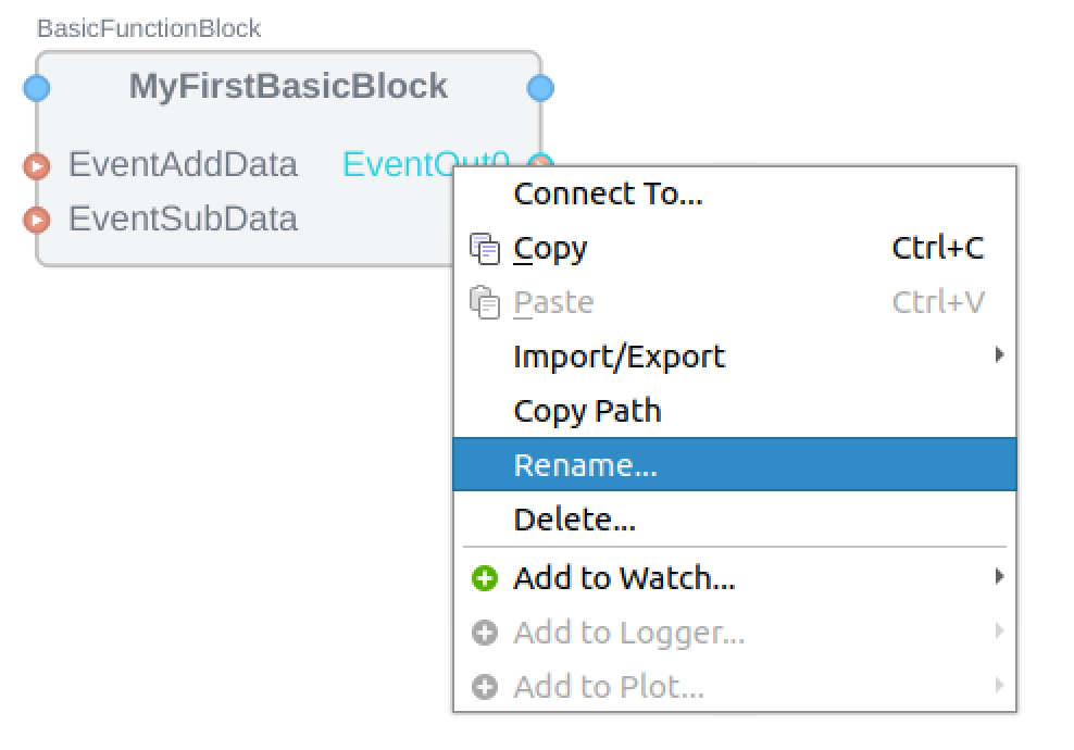
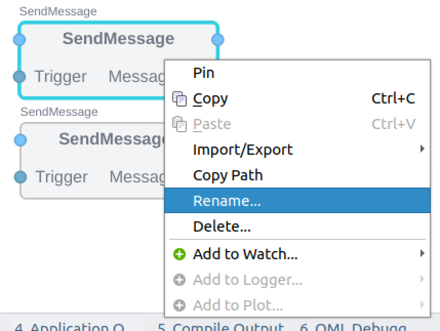
As the project grows, renaming your block with appropriately will make the program more readable: right-click on the Block>Rename.
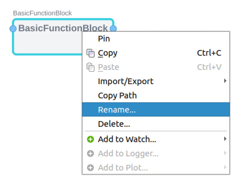
This time, change the name to MyFirstBasicBlock.
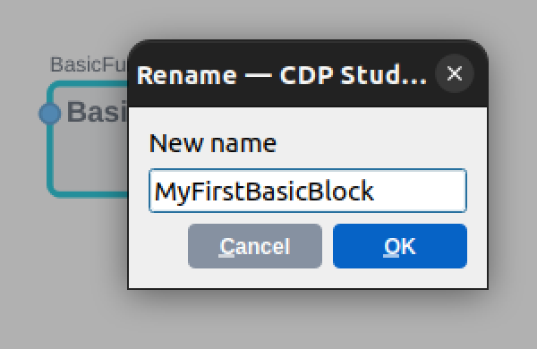
Done!
Add EventIn
Add a trigger EventIn to execute the BasicFunctionBlock program in Flow.
Drop the EventIn component directly into MyFirstBlock.
Just like this.
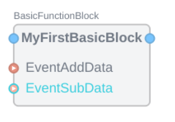
Add two EventIns and rename them appropriately, as in the previous GIF.
Don’t forget to change the name for clarity.
Done!
Add EventOut
Add an EventOut for the BasicFunctionBlock program in Flow.
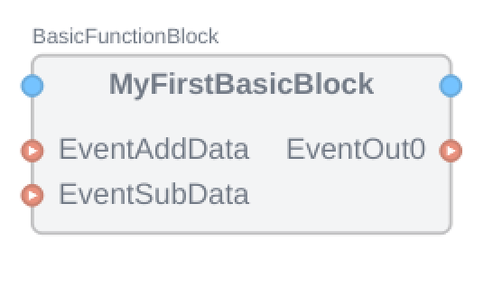
Drop the EventOut component directly into MyFirstBlock.
EventOut0 has been added to MyFirstBasicBlock.
Don’t forget to change the name for clarity.
Edit BBC
Next, let’s add the internal program of the Basic Function Block.
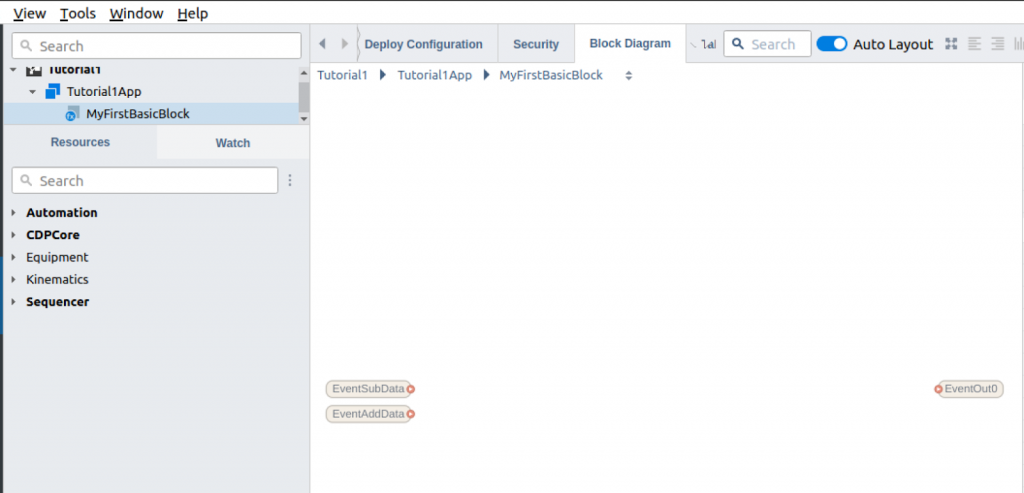
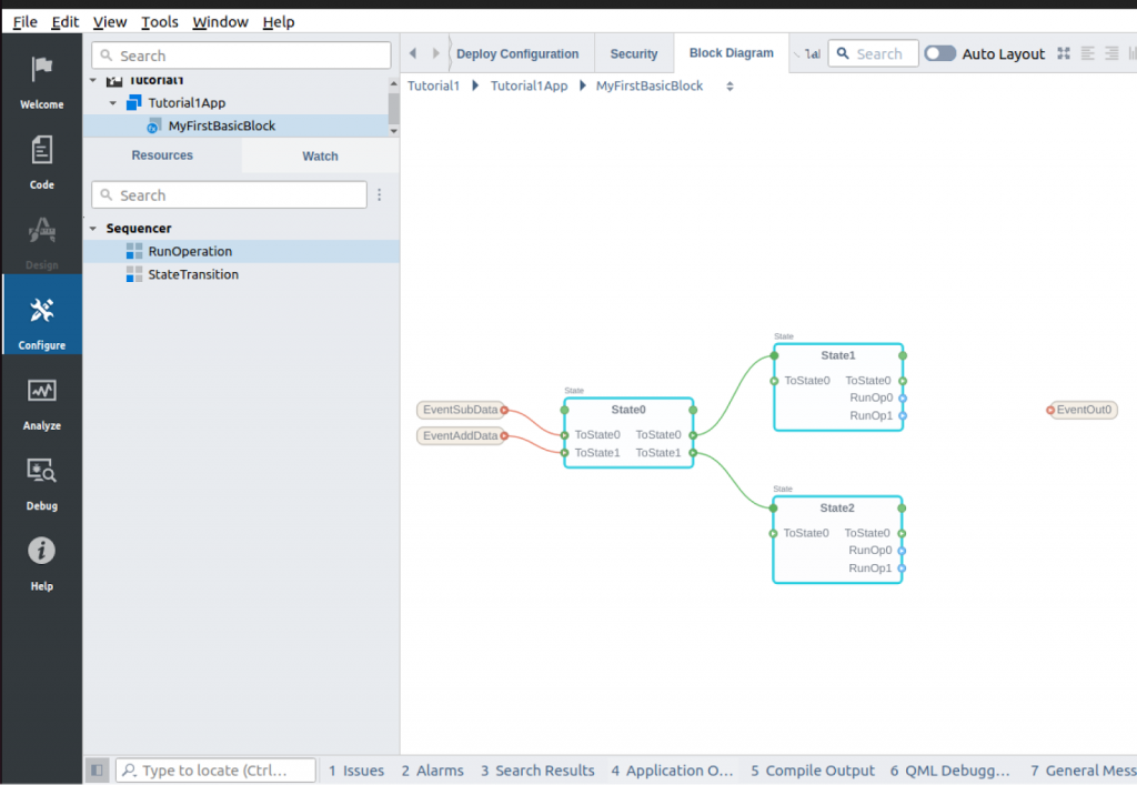
Double-click the MyFirstBasicBlock that you just modified.

You can see the contents of MyFirstBasicBlock.
Add State1 – Waiting Trigger
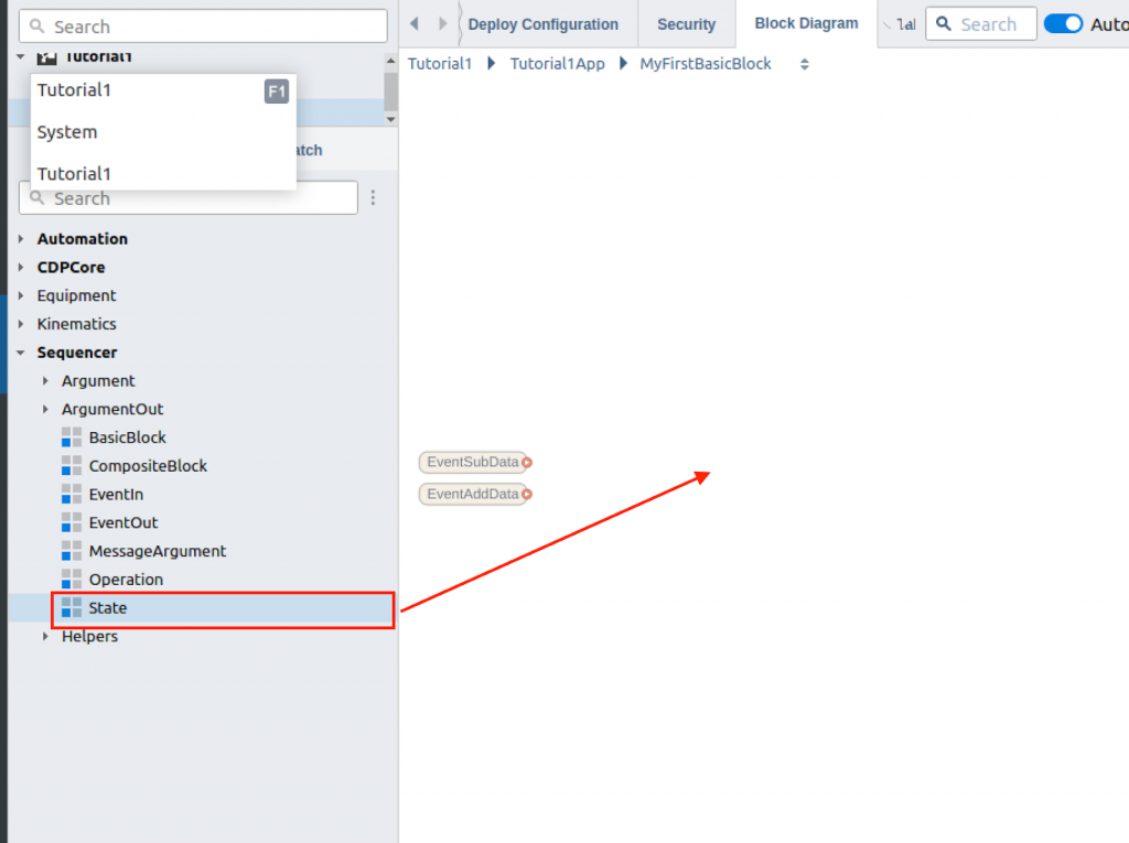
First, let’s add State1, which receives the Event trigger.

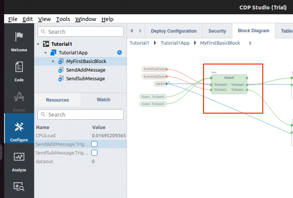
Select Sequencer>State>Add to free space in MyFirstBasicBlock.
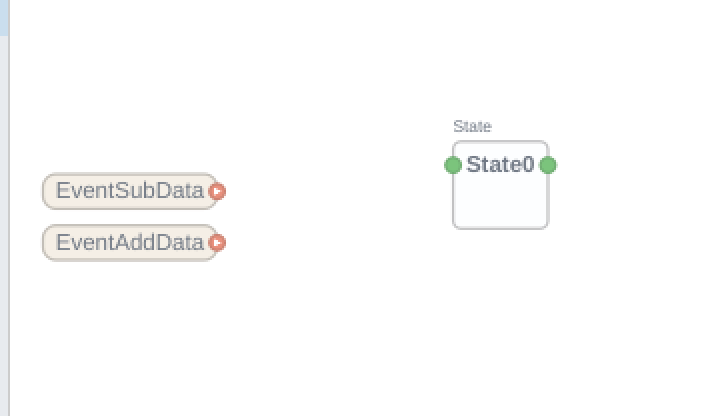
Done!State0 has been added.
Add State Transition
The next step is to make the connection between Event Input1, Event Input2 and State1.
Add Sequencer>State Transition to the “State0” Block.
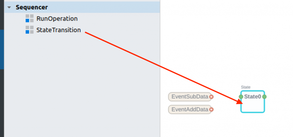
Just like this.
Now we have created a part that transitions between the “ToState0” and “ToState1” states in the State0 Block.
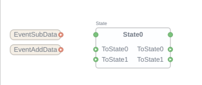
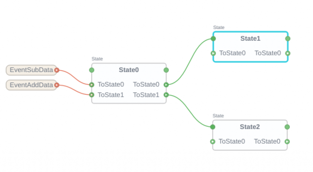
Connect Event Input to StateTransition
Now we can connect the Event Input trigger and the state transition part of State0.
Thus, Let’s connect EventSubData to ToState0 and EventAddData to State1.
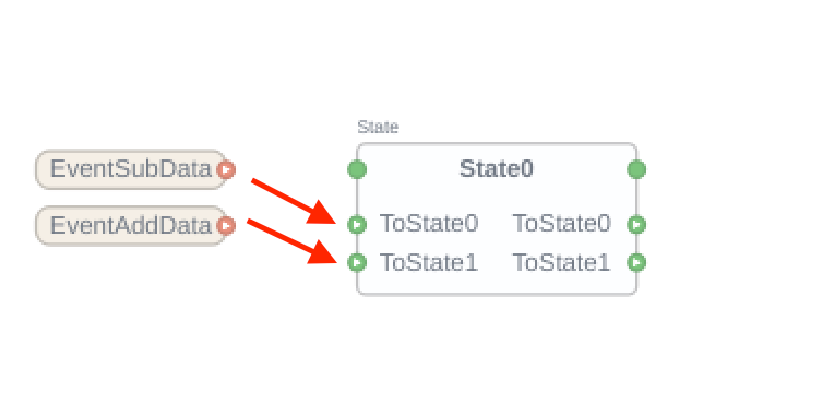
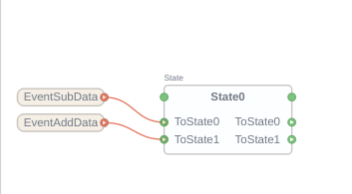
Done! When EvnetSubData triggers, ToState0 receives a message and transitions to the state connected to ToState0. Conversely, when EvnetAddData is triggered, ToState1 receives a message and transitions to the destination state of ToState1.
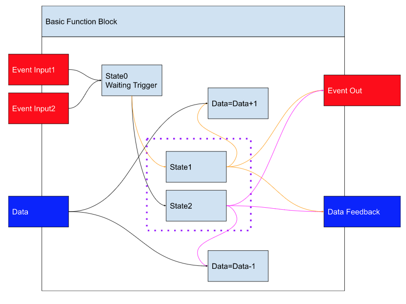
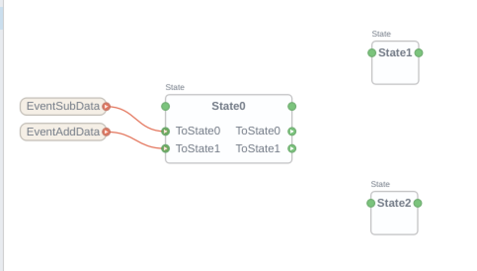
Add State1,2
Now we create the transition destination part of State0, which corresponds to State1/State2 in the Flow diagram.
Sequencer>Add two States.
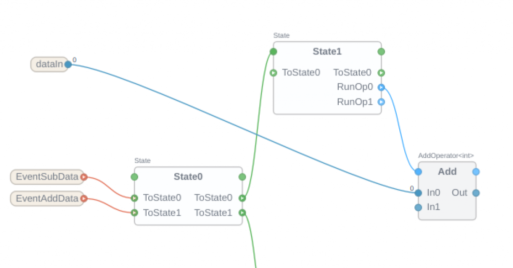
Connect Transition Between 1 State0 to State 1/2
Create a transition Connection between State0 and State1/2.
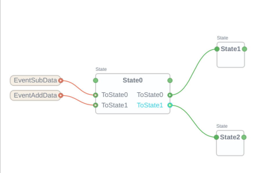
Connect “ToState0” and “ToState1” on the right side of State0 with the green area on the left side of State1 and State2 by a line.
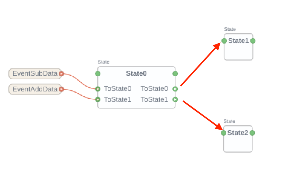
Done! Now State0 outputs “ToState0” transitions to State1 and “ToState1” transitions to State2.
Add State Transition In State 1/2
Let’s edit State1,2 .
Sequencer>Add two States.
Add RunOperation in State1,State2
In the Flow diagram, State1 has Data+1 and State2 has Data-1 control, and we will create this part now.
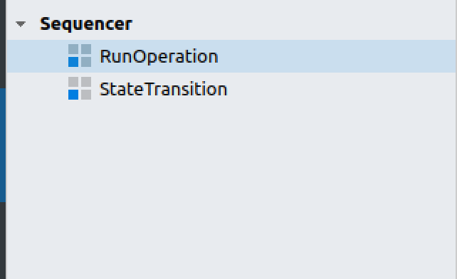
You can see RunOperation inside Sequencer.
Add RunOperation to the State Block.
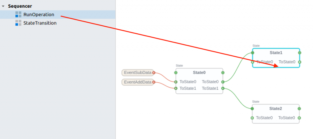
Just like this.
Now when the program is in State1, it executes the RunOp0 and RunOp1 algorithms, and when it is in State2, it executes RunOp1 and RunOp2 in State2.
Add Operation
First, implement the Data+1 portion.
Automation>Add>Add<int>.
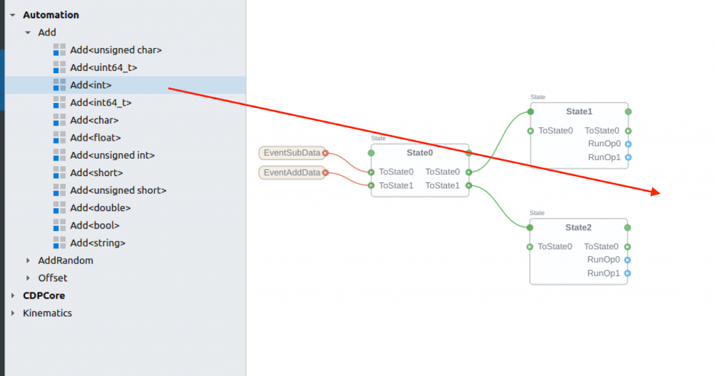
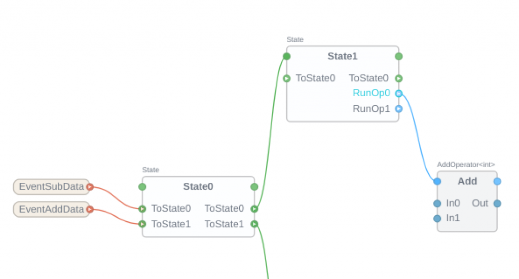
Connect RunOp0 of State1 to the blue colored part of the “Add” Block.
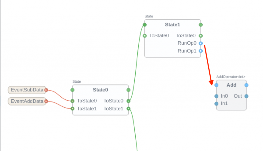
Done! If the program is now in State1, the destination Add Block of RunOp1 will be executed.
Add Data Argument
We defined the Data Input first for the BasicFunctionBlock, so let’s add the Data Argument to our project.
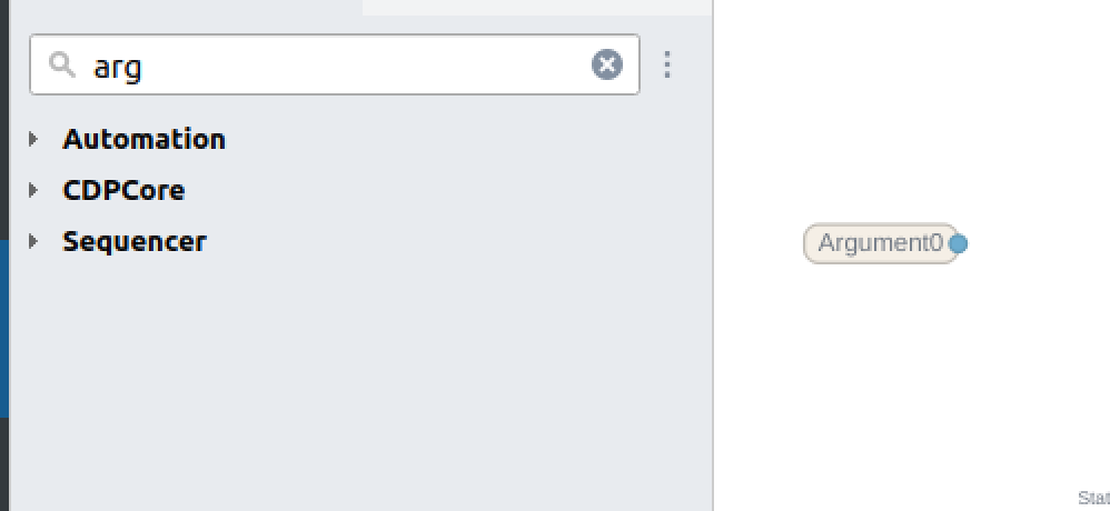
Add Sequencer>Argument>Argument<Int> to the project.
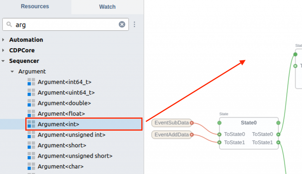
Done!
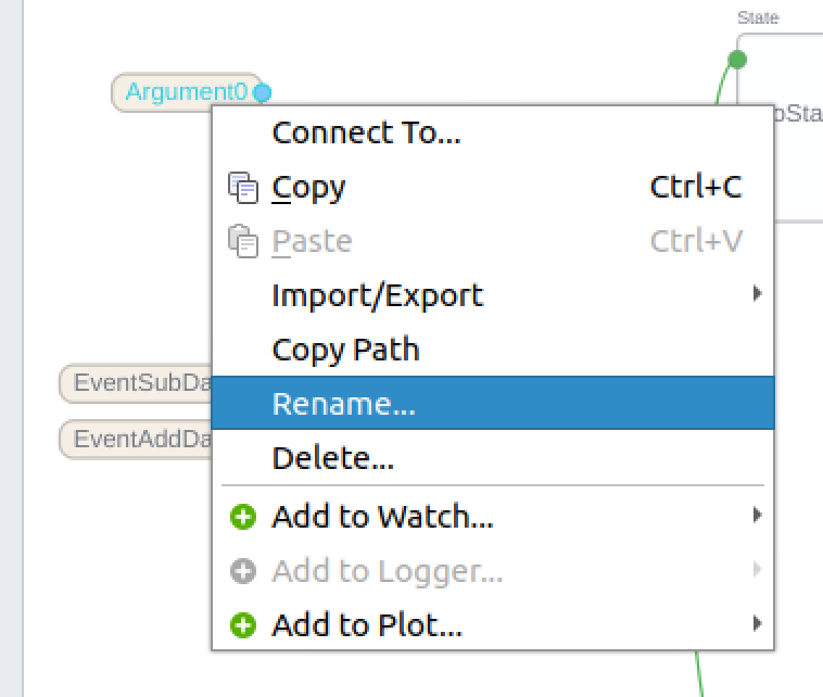
Don’t forget to change the name for clarity.
Data Argument is connected to In0 of Add Block.
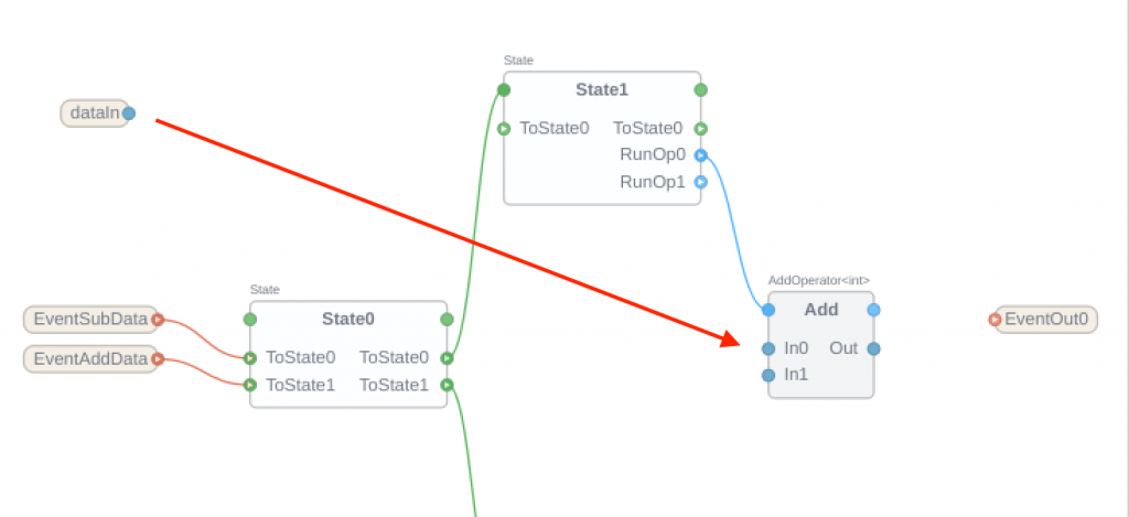
Done! Now In0 of Add Block refers to the dataIn.
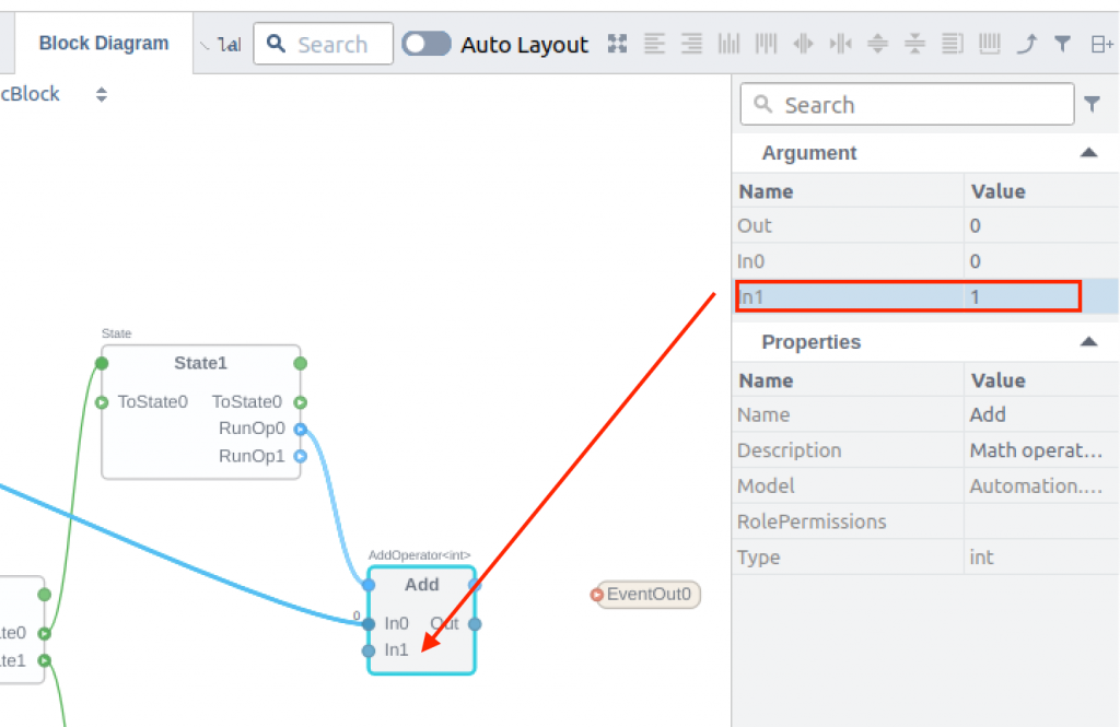
Click on “Add Block” and the Properties of that block are displayed.
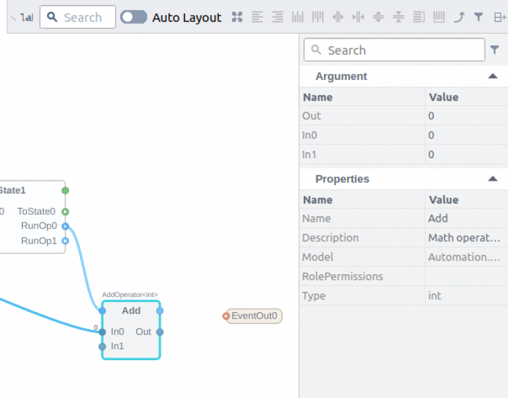
Set the Value of In1 to 1. Now In1 of Add Block is always set to the constant “1”.
Configure EventOut
Now we will create the flow from State1 to EventOut output.
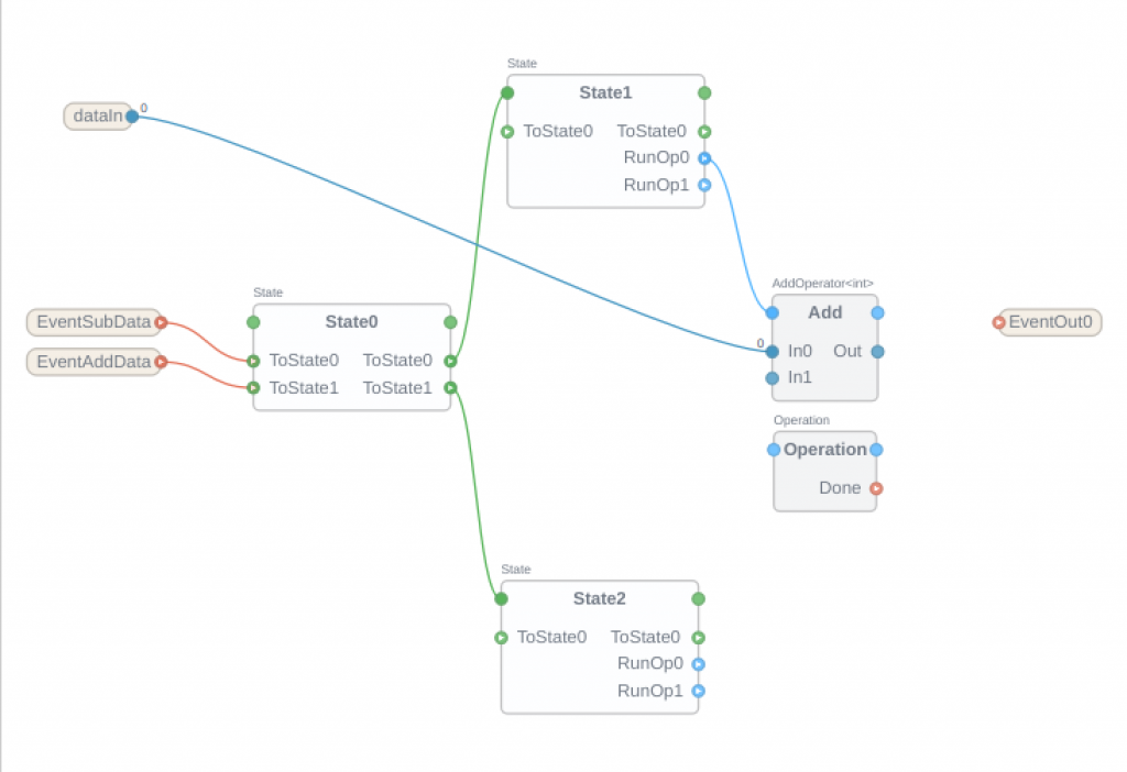
Add Sequencer>Operation to the project.
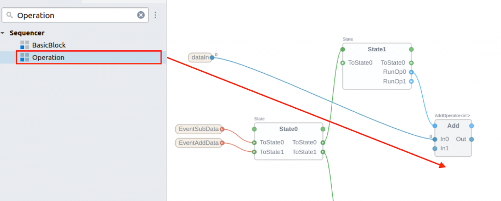
EventOut0 has been added.
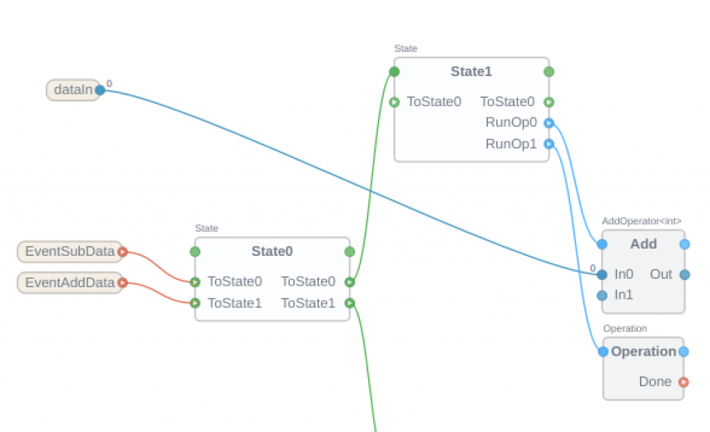
Connect RunOp1 of State1 with Operation.
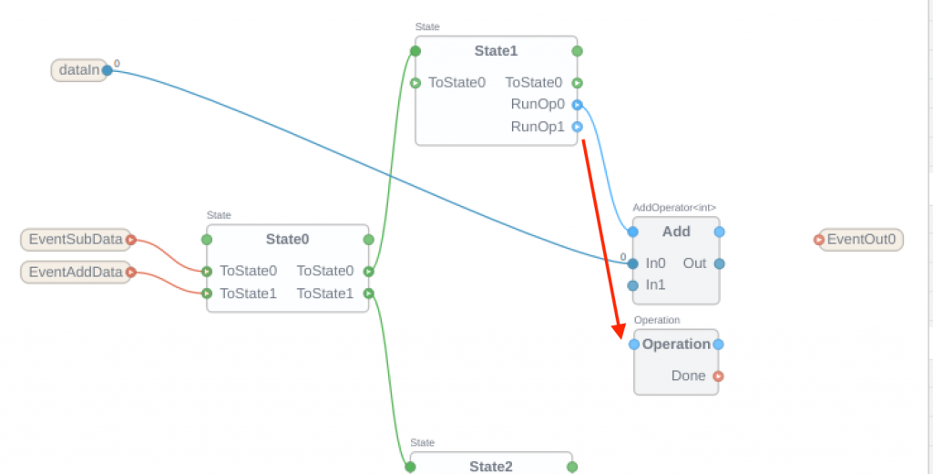
If the program is now in State 1, Block Add and Operation will also be executed at the same time.
Finally, the output “Done” of the Operation Block is connected to EventOut0.
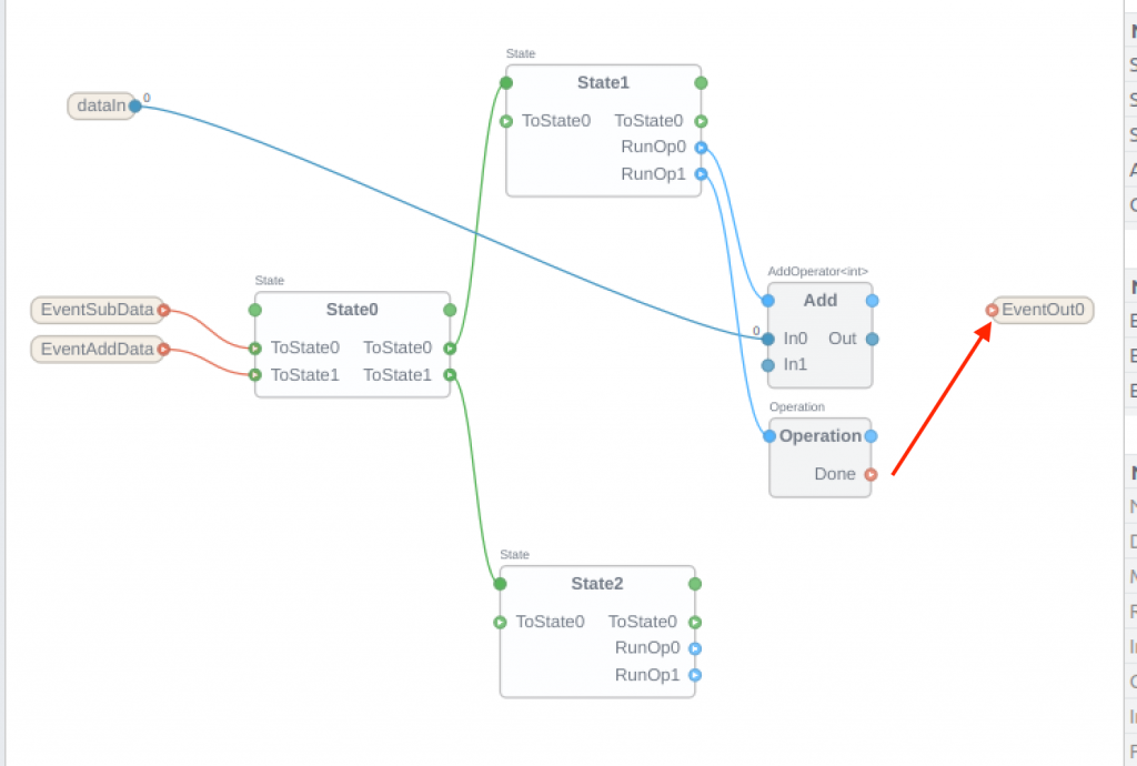
The EventOut0 is output while Done of Operation is completed.
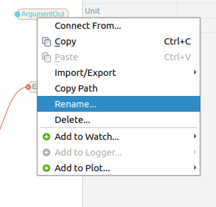
Add ArgumentOut
Then we can program the output Data processing for BasicFunctionBlock.
Add Sequencer>ArgumentOut>ArgumentOut<int> to your project.
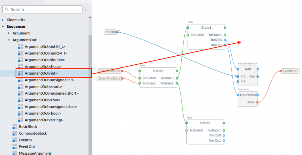
Change the name to something easy to understand.
Configure the Connection with Argument Out
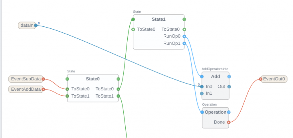
To output the processed data from BasicFunctionBlock, let’s connect the ArgumentOut we just added with Add block.
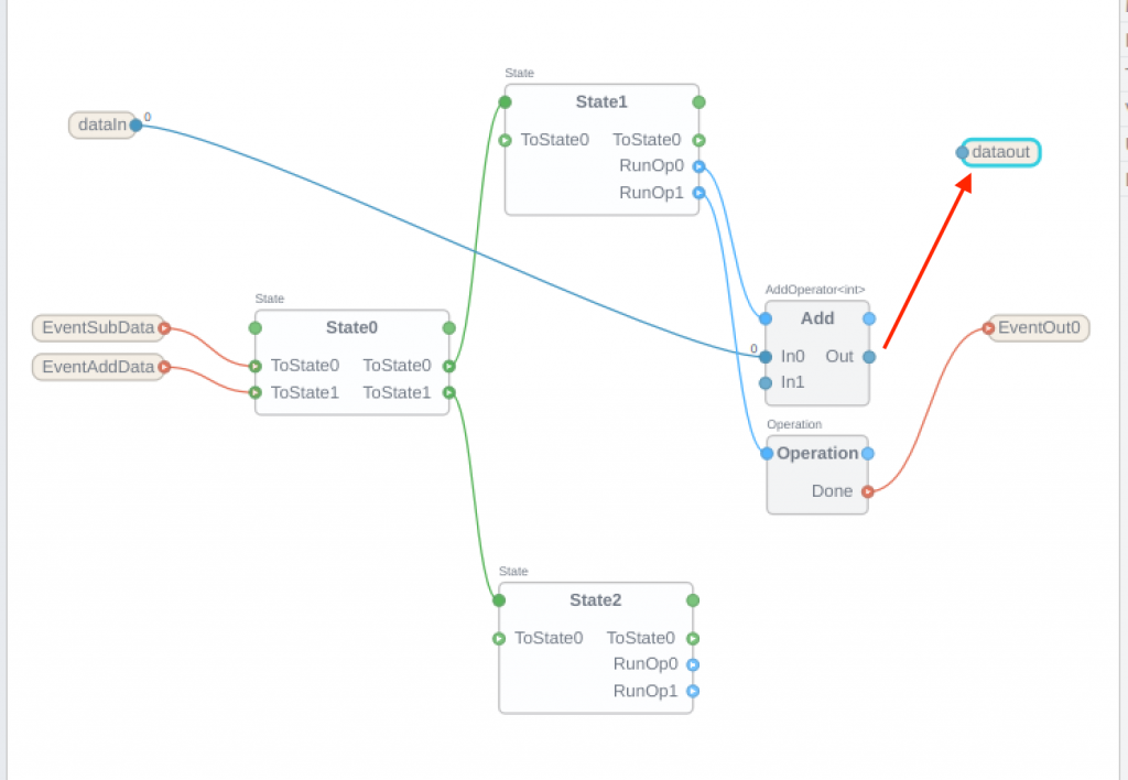
Done!Now the result of the Add Block operation is output to ArgumentOut.
Add Subtract Block
Create the Subtract portion of the Flow diagram.
Add Automation>Subtract>Subtract<int> to the project.
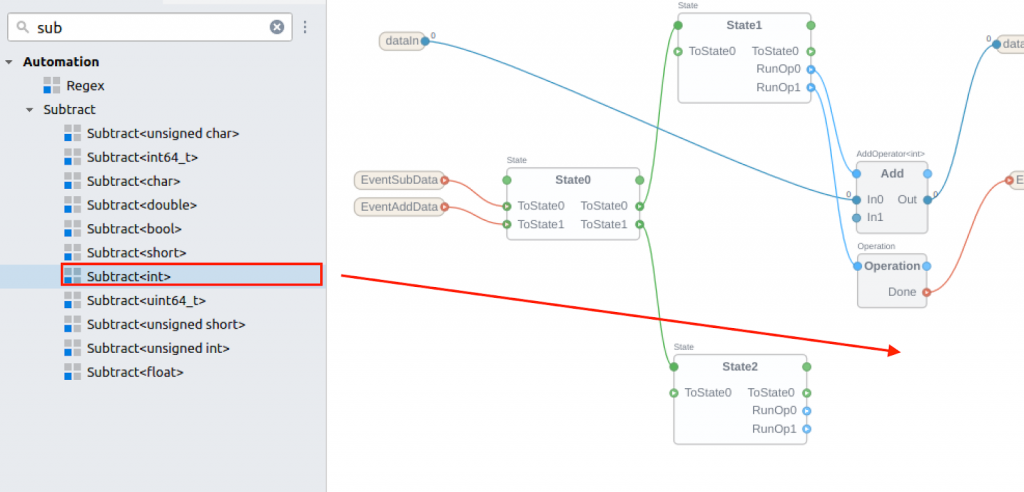
Create a program in the same way as the Add Block described earlier.
Loop Back
Add a new behavior to the Flow diagram so that the BasicFunctionBlock transitions back to State0 after State1 has completed processing.
Connect the “ToState0” contact of State1 to the green part of State0.
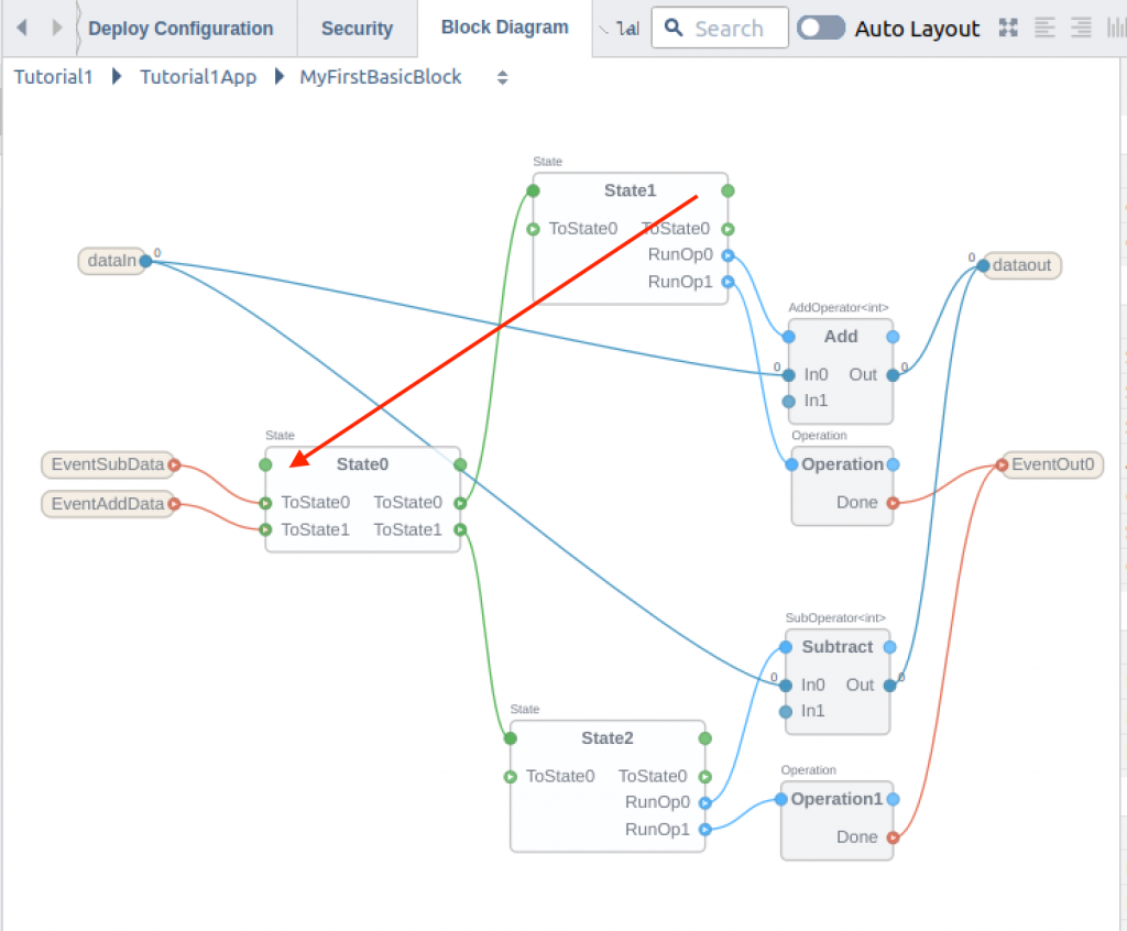
Just like this.
Done!Since State1 is now connected to ToState0, it will return to State0 at the end.
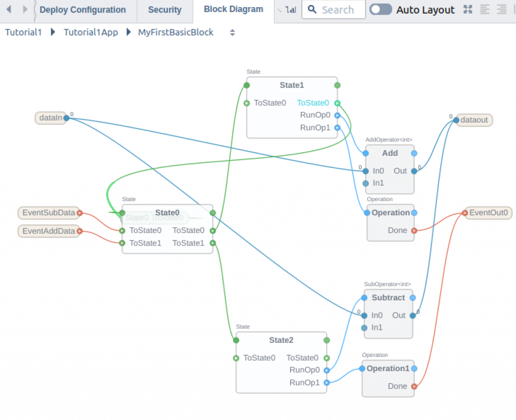
If you move the “State1” Block a little bit, you will find a State0 Node and a trigger for State1.ToState0.
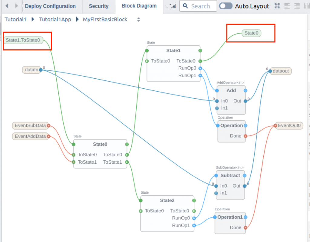
Operate State2 in the same way.
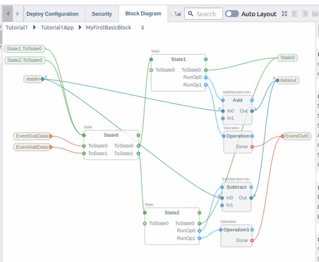
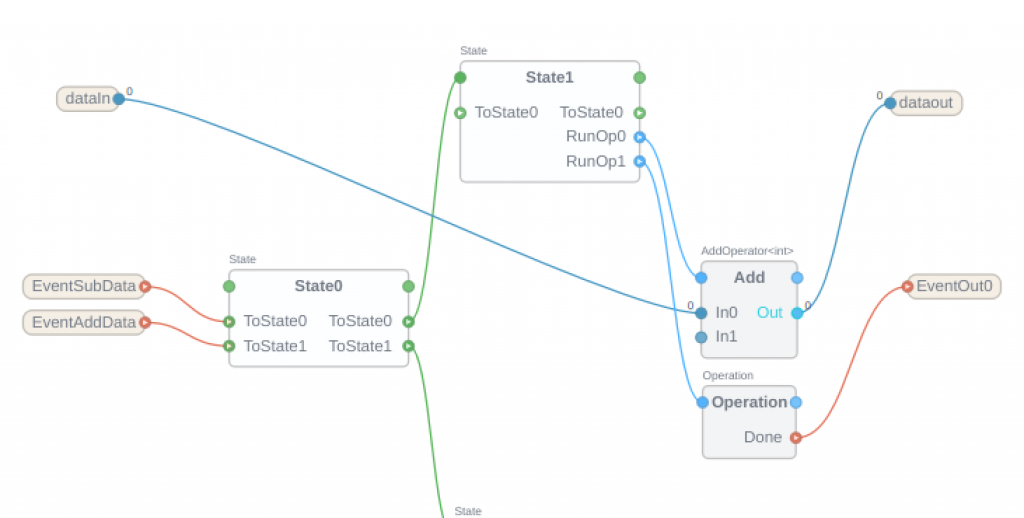
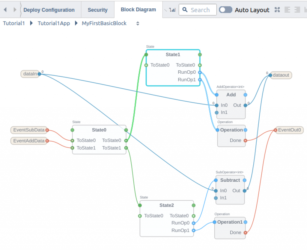
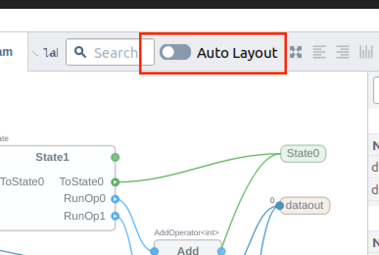
Auto Layout
As the program becomes more complex, the block will become more and more complicated. Here, the “Auto Layout” button allows CDP Studio to automatically adjust the layout.
Done!
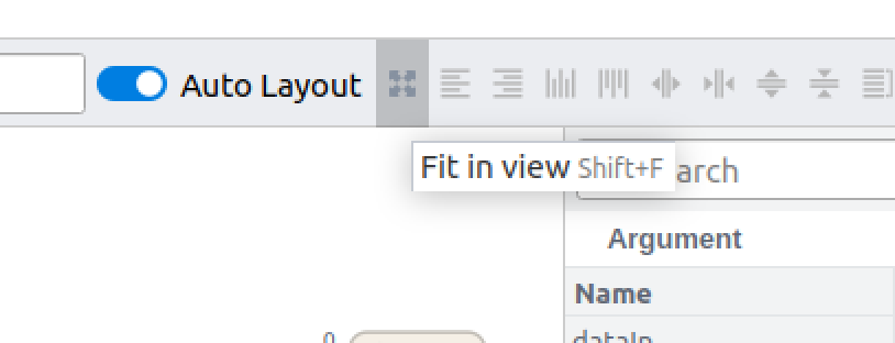
Fit in View
When the program becomes complex, the Zoom ratio may be incorrect, if you want to check the overall flow, there is a useful feature called “Fit in view”.
Done!
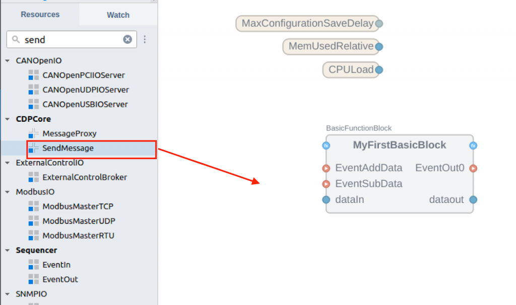
Send Message
It is necessary to send a Message to trigger Event Input1 and Event Input2.
Once back to MyFirstBasicBlock.
Add the CDPCore>SendMessage component to your project.
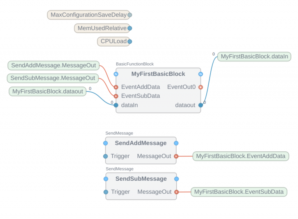
Okay, now I have added a SendMessage Block that triggers EventAddData and EventSubData.
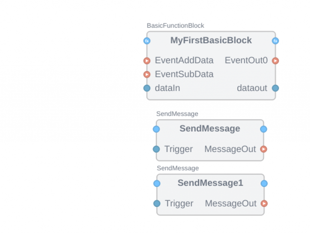
Change the name to something easier to understand.
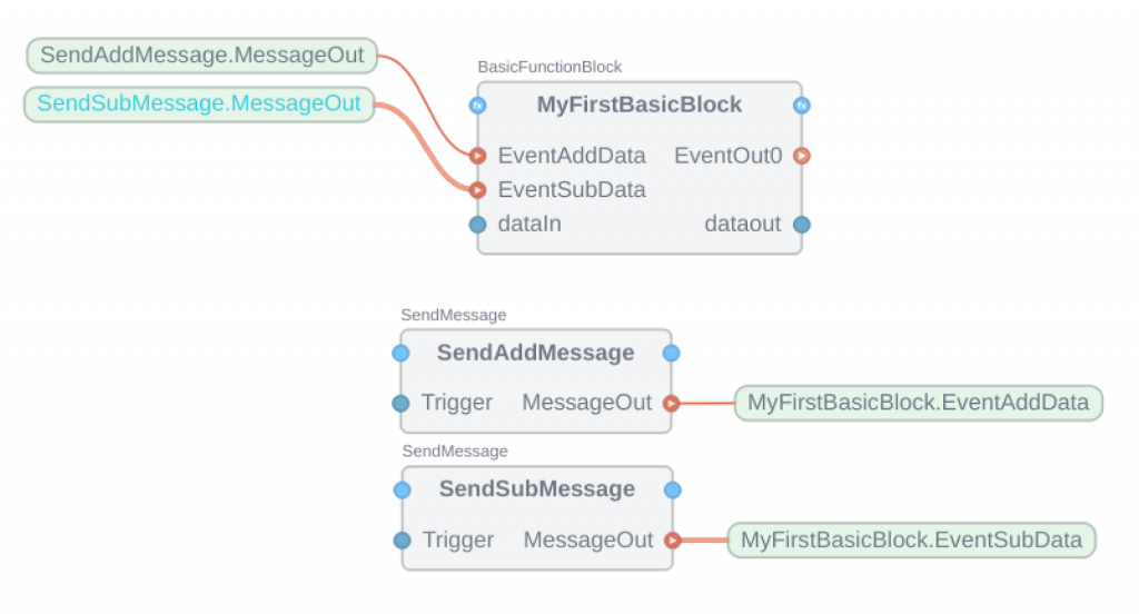
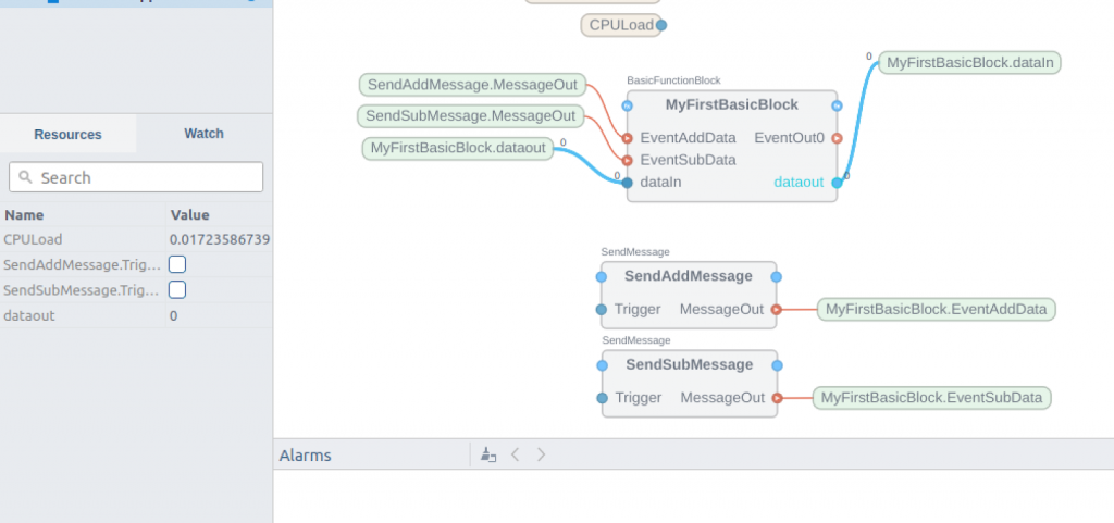
Connect MessageOut of SendAddMessage with EventAddData of MyFirstBasicBlock.
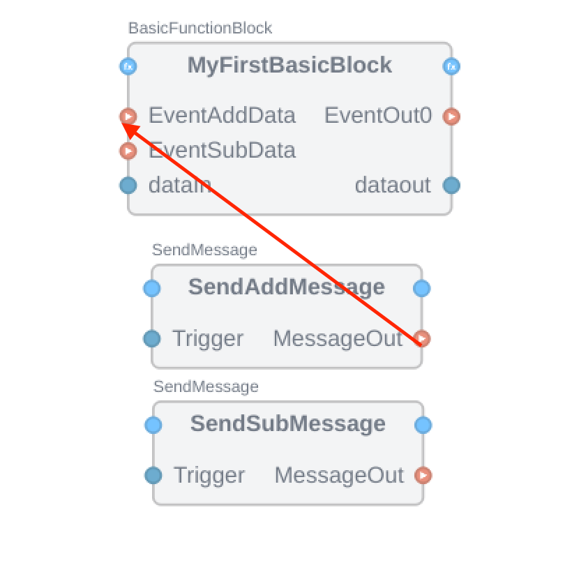
Just like this.
EventSubData should be operated in the same way. Now when the MessageOut of SendAddMessage becomes Ture, EventAddData will be triggered, and when the MessageOut of SendSubMessage becomes Ture, EventSubData will be triggered.
Data Loop Back
Finally, connect back the data output of MyFirstBasicBlock as your data input.
Let’s connect dataOut of MyFirstBasicBlock with dataIn as it is.
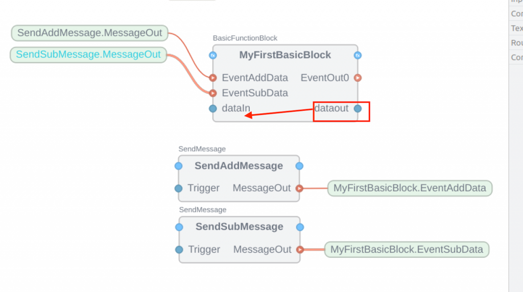
Just like this.
Done! Program is finished.

Deloy
The last step is to download the project to Runtime (Local in this case).
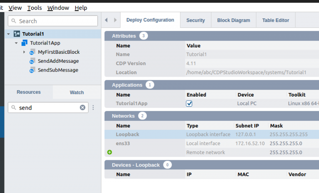
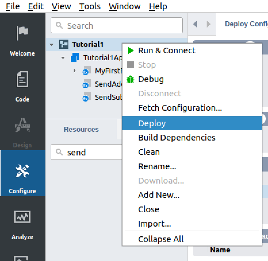
Click Project>Right click>Deploy.
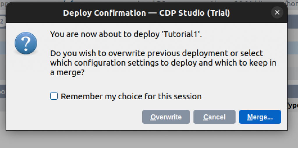
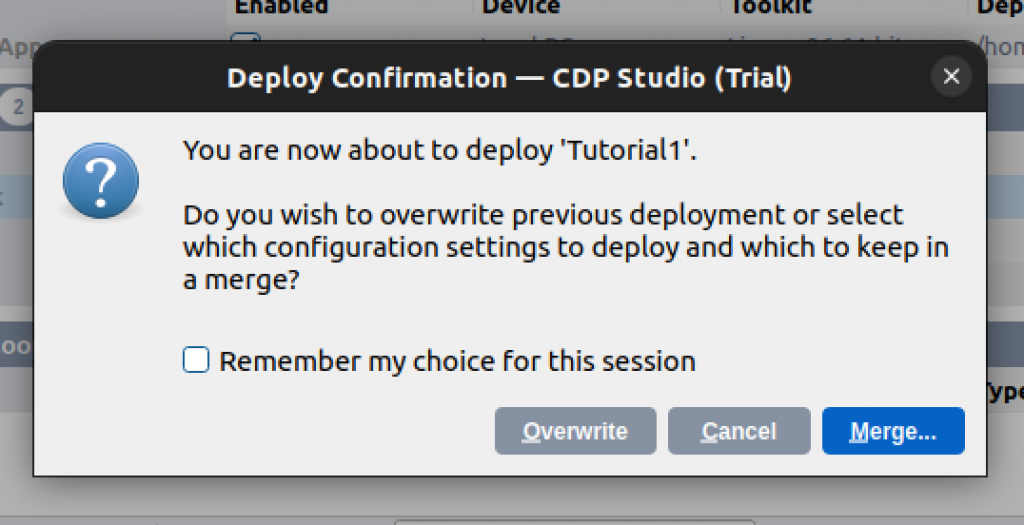
Proceed with Merge.
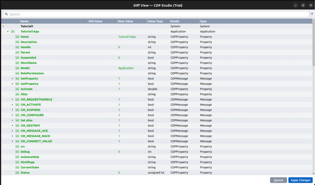
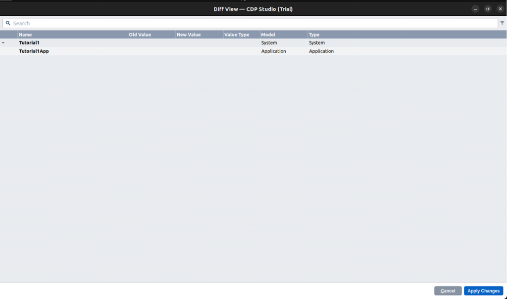
Now you can see a list of changes, additions, and deletions in the project.
Click on “Apply Changes” to proceed.
Just a second..
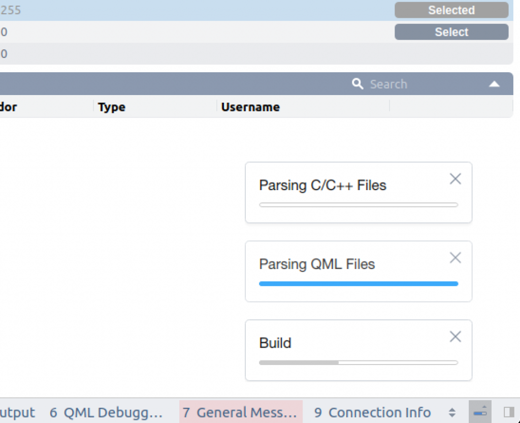
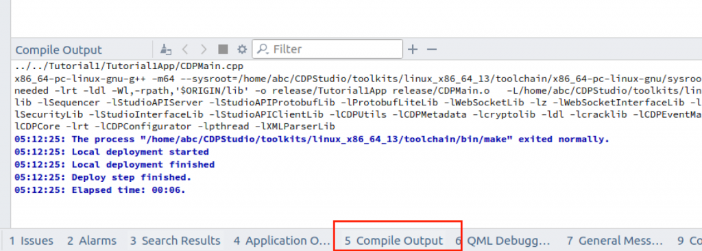
Open the Compile Output tab and check for errors.
Online
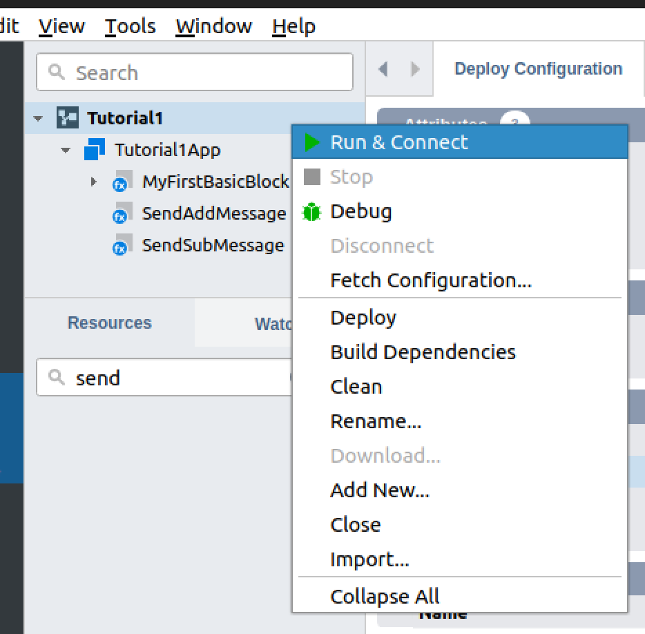
Right-click on the project>Run and Connect to run the project.
Proceed with Merge.
Okay, there are no changes in my project anymore.
Back to the project.
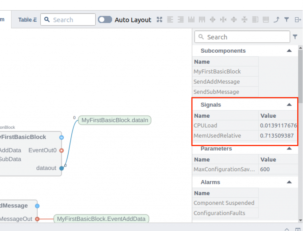
In the Signals section, you should now see the values of CPULoad and other variable changes.
Watch Table
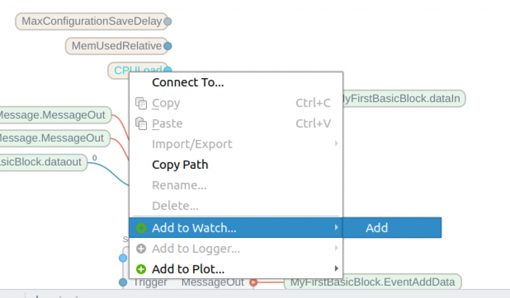
The last section shows how to add the variable to the Watch Table.
You can add what you want to monitor to the Watch Table by going to Tag>Right click>Add to Watch>Add.
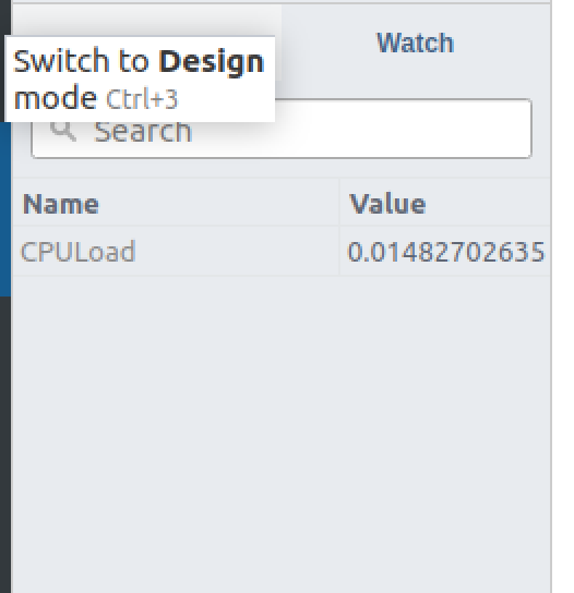
Done!
Use the same operation to add SendAddMessage and SendSubMessage Triggers to the Watch Table.
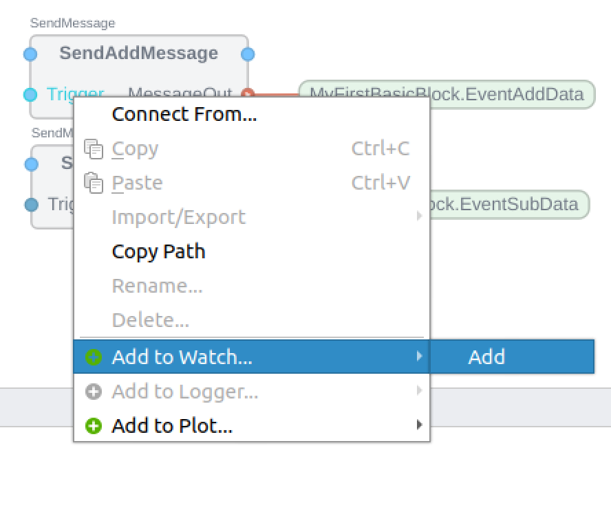
Done!
Result
Since Trigger is Binary data, it can be changed to Ture or False by Check/UnCheck of Value.
Such DataOut also converts the current value as plus/minus.
When you open MyFirstBasicBlock, State0 turns green, because this Block is now in State0.
It may be a little difficult to see, but State1 and State2 are also shown as blinking green. This is because the state has transitioned within the FB.