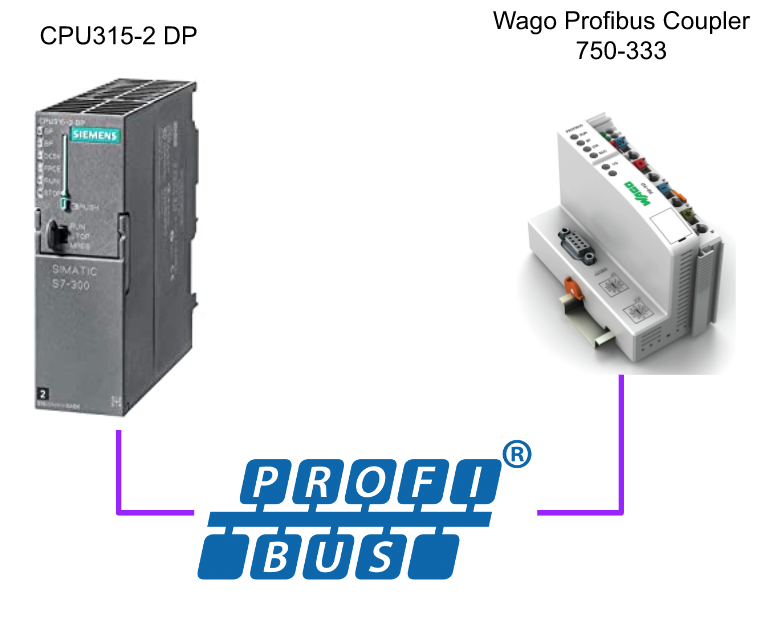
In this article we will use Wago’s 750-333 Profibus Coupler and connect it to Siemens’ S7-315DP to create a Profibus DP network.
Let’s Start!
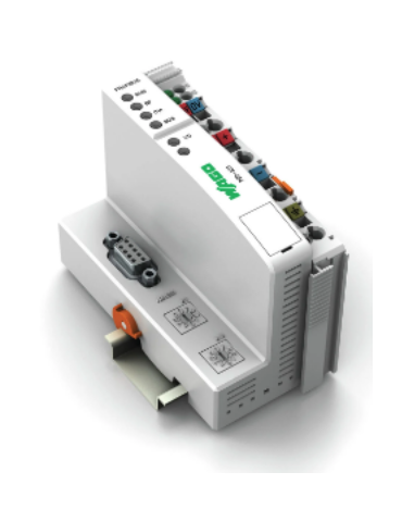
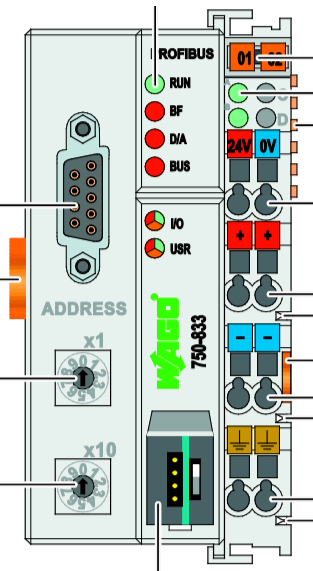
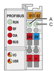
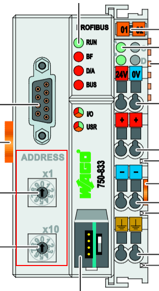
750−333
This is Layout of a 750-333.
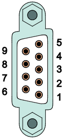
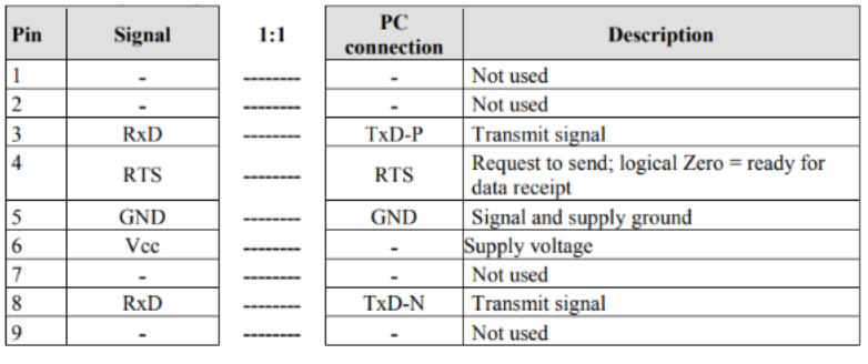
D-Sub Connector
This is the Pin for Wago’s D-SUB Connector.
LED
The LEDs on the 750-333 allow you to check the current module status.
Field bus Status
| LED | Color | Description |
| RUN | GREEN | Communication between PROFIBUS Master and Coupler is normal. |
| BF | RED | Indicates whether the PROFIBUS communication function is normal. |
| DIA | RED | Indicates the diagnostic status of the extension |
| BUS | RED | PROFIBUS indicates parameterization and Configuration errors |
Node Status
| LED | Color | Description |
| I/O | GREEN/RED/ORANGE | Indicates the operating status of the Node |
Supply Voltage
| LED | Color | Description |
| A | GREEN | Indicates the power supply status of the System |
| B/C | GREEN | Indicates the power supply status of Power Jumper |
Rotary Station Address
The 750-333 sets the Node address from two Rotary Switches. For example, if x1 is set to 3 and x10 is set to 2, the address of 750-333 will be 23.
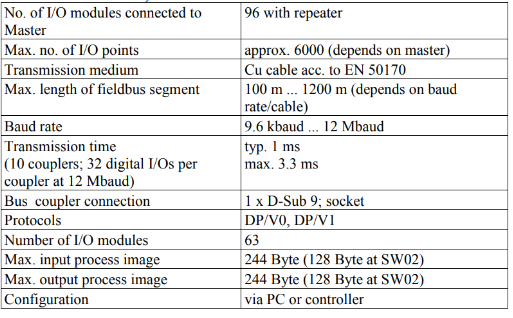
System Data
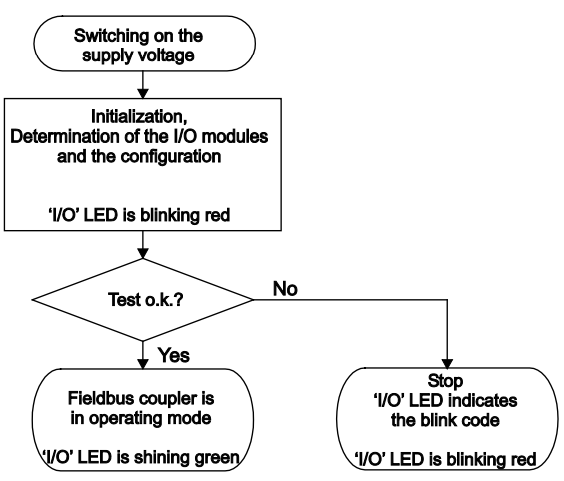
Flow
This is the internal flow of the 750-333: upon Running Up or Reset, the 750-333 initializes and compares the current Configuration with the connected IO module. (The LED will then flash red.) If there are no errors, the 750-333 will initialize and compare the current Configuration with the connected IO module.
>If there are no errors, the 750-333 will switch to “Fieldbus Start Mode” and the RUN LED will flash green.
>If there is an error, the 750-333 will flash the I/O LED red.
Baisc
The 750-333 can mix digital inputs, outputs, and Function Modules and uses K-BUS to exchange Process Data and Fieldbus Coupler.
Note that some IO modules cannot be used depending on the firmware of the Fieldbus Coupler.
Be Careful!
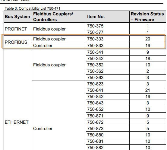
There are restrictions not only on the 750-333, but also on the Controller and Coupler firmware versions. For example, the firmware of the 750-333 that using this time is V17, I cannot use the 750-471’s 4-point analog input with FW20 at a minimum.
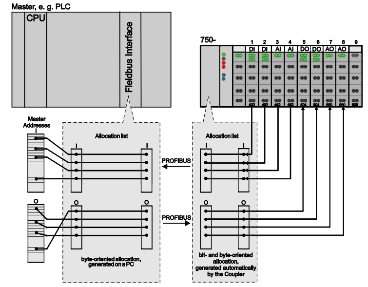
In/Output Data
Regarding mapping, the 750-333 can exchange up to 244Bytes of process data with the Master via Profibus. In fact, the IO Module settings installed on the 750-333 must be imported into the Profibus Master software (in this case, Step7 V5.7 Classic) by using the GSD file.
GSD File?
To build a PROFIBUS DP network, a GSD File (General Station Description) provided by the manufacturer is required, which defines the functions of the Profibus Slave.
For example, the 750-333 used in this project can be downloaded from WAGO’s website.
About Profibus
Let us introduce Profibus, the Open Fieldbus according to DIN 19 245. The Profibus DP (DP stands for Deecentralized Peripheral) is a version of Profibus that is easy to build and allows efficient data exchange with PLCs and PCs.
The DP System includes a DP Master and up to 125 Slaves,and asynchronous communication is also supported from PROFIBUS DP/V1.
ThePROFIBUS communication speeds range from 9.6 kBaud to 12 MBaud.
DP Master
DP Maseter is responsible for data exchange and monitoring with DP slave via PROFIBUS DP.
DP Slave
This device is linked to the PROFIBUS DP Network and receives output data from the Master and feeds back input data.
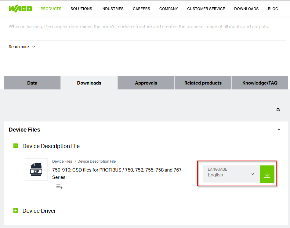
Download GSD Files
First, download the 750-333 GSD File from WAGO at the following Link.
https://www.wago.com/global/i-o-systems/fieldbus-coupler-profibus-dp/p/750-333#downloads
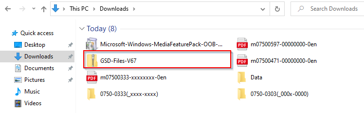
A Zip File like this should have been downloaded.
Which One?
Since we will be using 750-333, we will unzip the Folder 0750-0333.
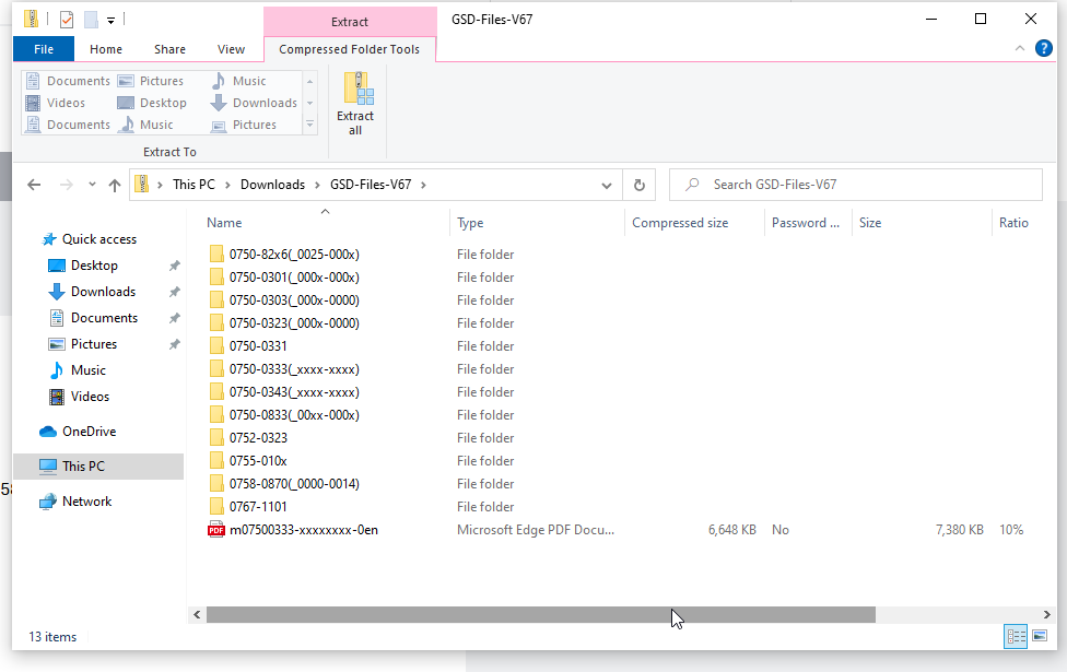
But there are still many Folders inside. Which one should I use?

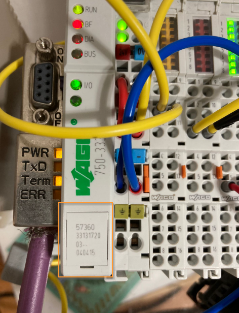
Do you see numbers like 33131720 in the 750-333 Profibus Coupler?
Actually, as I mentioned in the ReadME File, that number is the Coupler’s production information.
As for the Format,
WW YY SW HW FWL -xh1h2h3 in,
WW=weeks manufactured
YY=Year manufactured
SW=Software Version
HW=Hardware Version
FWL=Firmware Loader Version
-xh1h2h3=Internal number
This time on my 750-333 it is 33131720, so WW=33, YY=13, SW=17, HW=20.
That means it was manufactured in the 33rd week of 2013, Software Version is 17, Hardware Version is 20, and with that much information, I know what Folder to use.
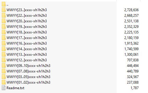
If you look at the Folder again, you will see WWYYY[23…]. The naming rule for the folder is xxxx-xh1h2h3.
You don’t have to worry about WWYY because it is the Week of Manufacture and Year, but the [23…] indicates its Software Version. In other words, my Coupler is Version 17, so WWYY[17..]. Folder of xxxx-xh1h2h3 is used.
Implementation
Now let’s actually build a Profibus Network with Siemens’ S7-315DP and Wago 750-333.
Add S7-300 Station
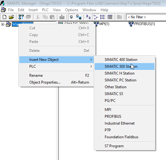
Start SIMATIC Manager and click on Project>Right click>Insert New Object>SIMATIC 300 Station.
A new S7-300 Station has been added.
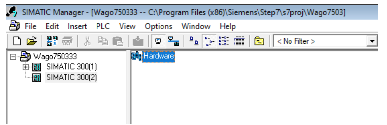
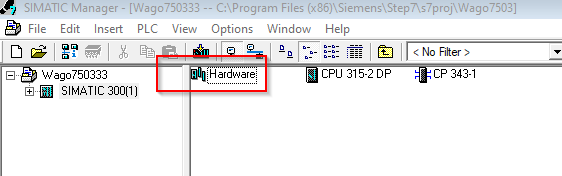
Install GSD Files
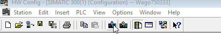
Next we will add the GSD Files; click on the Hardware button.
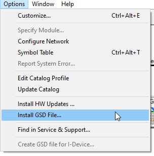
Options>Install GSD File.
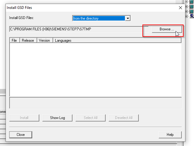
Select “From the directory” for Install GSD File and click the Browse button.
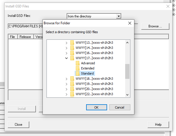
If you expand xxxx-xh1h2h3 that downloaded from Wago HP, you will find 3 Folders, Standard/Extended/Advanced, and this time you will install the Standard GSD File.
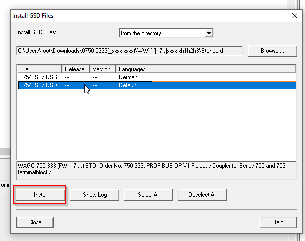
Select Default in Language > Install.
Configuration
DP Master
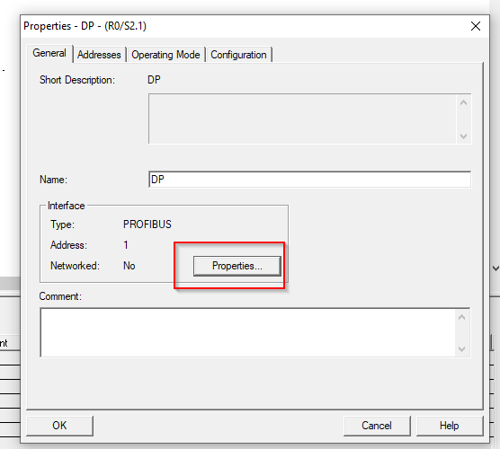
First, configure Profibus DP Master by clicking on “DP” on the CPU.
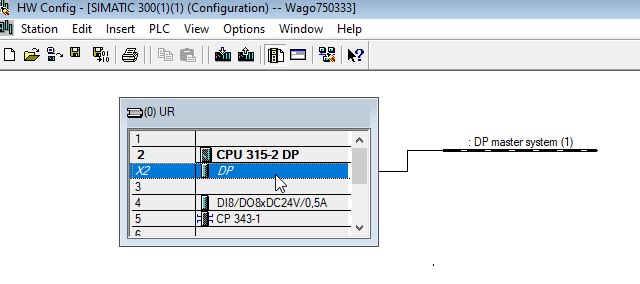
My CPU315-2DP still shows “No” for Networked. Click Properties to configure the Profibus DP Network.
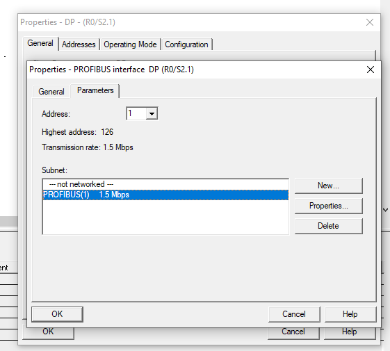
Select PROFIBUS(1) and OK.
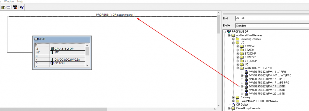
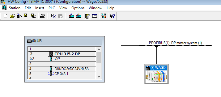
Add Wago 750-333 Coupler
Add the Wago750-333 Coupler into your configuration. Search for 750-333 in the Hardware Catalog on the right and add it to PROFIBUS DP Network.
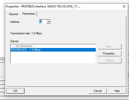
The Properties screen appears, set the Address to match the rotary switch setting of the WAGO 750-333 PROFIBUS Coupler, and press OK.
The WAGO 750-333 Profibus Coupler has been added.
Configure Slot 750-1417
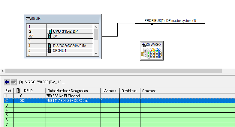
Add Input module 750-1417. Find 750-1417 in the Hardware Catalog on the right and pull it into Slot 2 of the Wago750-333.
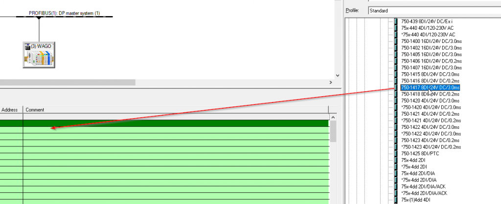
750-1417 8-point input module added with Input addresses from I1.0 to I1.7.
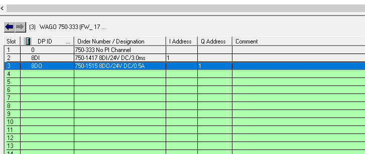
Configure Slot 750-1515
Add Output module 750-1515. Find 750-1515 in the Hardware Catalog on the right and pull it into Slot 3 of the Wago750-333.
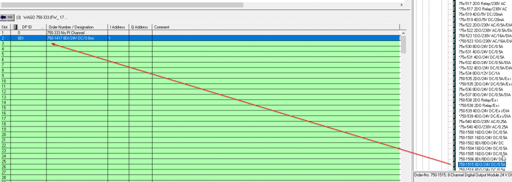
750-1515 8-point output module added with Input addresses from Q1.0 to Q1.7.
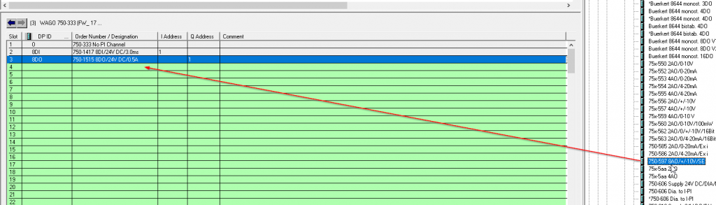
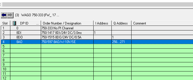
Configure Slot 750-597
Add the Analog Output module 750-1515. Search for 750-597 in the Hardware Catalog on the right, and pull it into Slot 4 of the Wago750-333.
750-597 8-point output analog module is added, with Output addresses from Q256.0 to Q271.7.
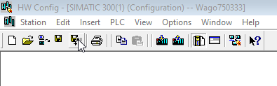
Complie
Compile the project and check for errors.
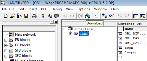
Download
Download the Project to the CPU.
Program
The last step is to create a program for testing.
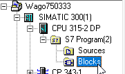
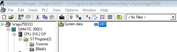
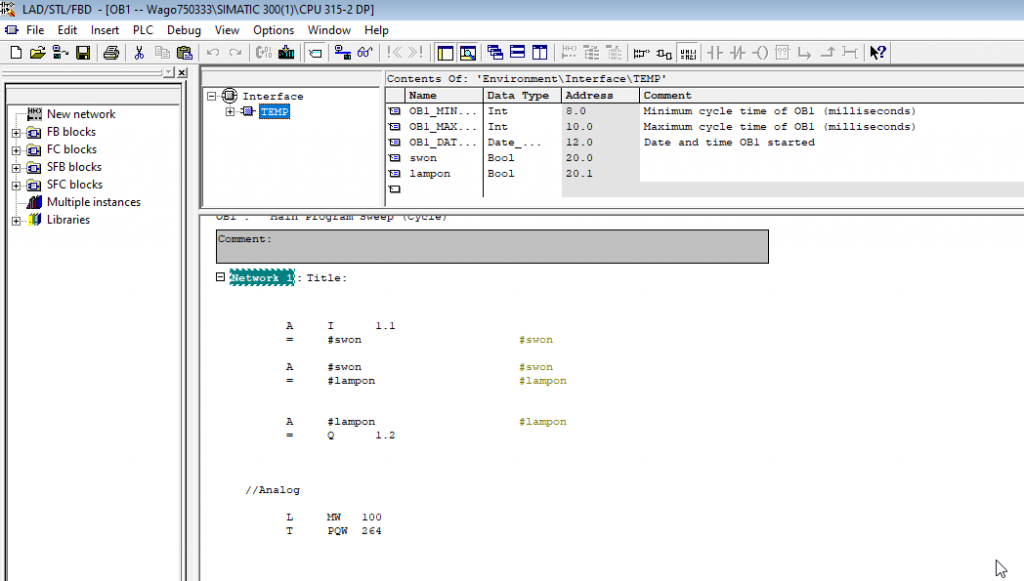
We will modify the program directly from OB1.
I1.1 is the second input, Q1.2 is the third output, and PQW264 is the fifth channel of analog output.
Download
Finally, download the program to the CPU.
コメント
isaac.baphe43@gmail.com
i wana know these one i am beginner
Siemens#Using D_ACT_DP to Disable the IO Devices
siemens s7000
hi
I want to connect 750-333 wago to 1200 siemens via profibus.
but i can not communication between 1200 & Wago
Can you help me?