Before we talk about IEC61449, you are probably familiar with PLCs, which are small controllers with Input/Output to control Motors, Valves, and so on. But if you are an engineer with an IT Background, when you talk about the PLC topic with them, they may think of Raspberry Pi, Arduino, or other embedded boards with input/output points.
But PLCs are specially prepared for industrial use and usually need to be programmed according to the following rules.
PLCs are also made by a variety of manufacturers. Unlike regular personal computers, PLCs are intended to operate efficiently for specific applications, and each PLC manufacturer develops these three parts.
- Hardware (like S7-1500 for Siemens or NX1 for Omron)
- Basic software (firmware) that runs on the PLC
- IDE (Integrated Development Environment, like TIA for Siemens, TwinCAT3 for Beckhoff, Gxwork3 for Mitsubishi)
To program a PLC, you need the IDE of the PLC vendor.
To put it simply, this is the general flow when using a PLC to make a device:
- Download the IDE from the manufacturer’s website>Install>Purchase a license if applicable
- Understand the functions of PLCs by examining their manuals.
- Learn how to use IDE and program your Application
- Connect PC and PLC, download the program and start debugging.
IEC61131-3
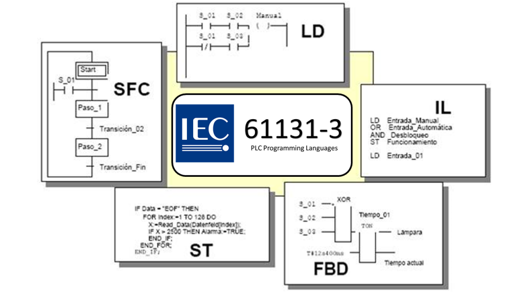
There is an international standard for PLC programming called IEC 61131-3. Although it provides each PLC with its own IDE, the programming language for PLCs was standardized in IEC 61131-3. This standard includes five different programming languages:
- Ladder Diagram (LD)
- Function block diagram (FBD)
- Structured Text (ST)
- Instruction List (IL)
- Sequential function chart (SFC),
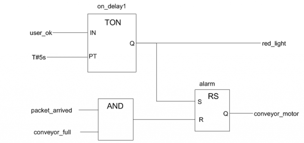
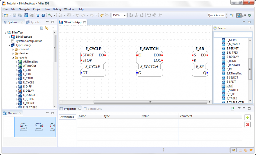
For example, in the case of FBD, we would write a program like this.
we will create the application in the IDE > compile it > and make sure there are no errors, download that compiled code to the PLC. Then, to make sure it works in the real system, you need to connect the PLC’s physical inputs and outputs to the actual sensors and motors. Each PLC manufacturer has its own way of representing physical inputs and outputs during programming. (For example, Mitsubishi uses XY, Siemens uses IQ, and Beckhoff uses %I* and %Q*.)
These languages are very different from high-level languages such as C, C++, Java, and Python, which have a particularly strong graphical component. But even some PLCs can create applications in these high-level programming languages.
IEC 61499
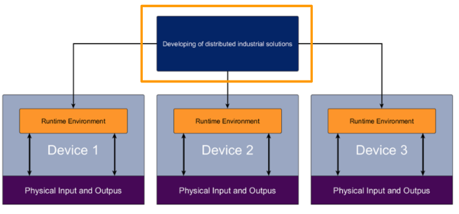
Until now, control systems have been strongly associated with central control, but IEC61499 is different.This approach provides a distributed industrial control solution.
distributed system?
A distributed system is one in which individual components have intelligence and communicate smoothly with each other to form a whole system. IEC 61499 standardizes a modeling language for developing such distributed industrial control solutions.
- Software encapsulation for increased reusability
- Vendor-independent Format
- Simplify support for controller-to-controller communication
- Extends IEC 61131-3
Function Block
Now I would like to introduce the Main part of IEC61499 – FB.
Interface
This shows the new look of FBs in IEC 61499; the basic idea of the Function Block is the same as in IEC 61131-3, but the purpose is to encapsulate the required functions.
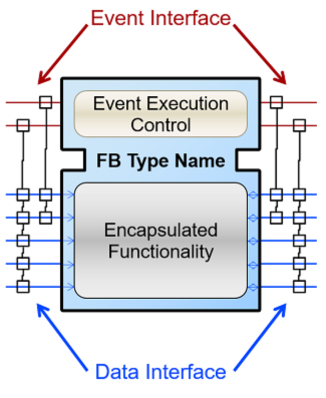
Input/Output
Input is left and output is right.
Interface
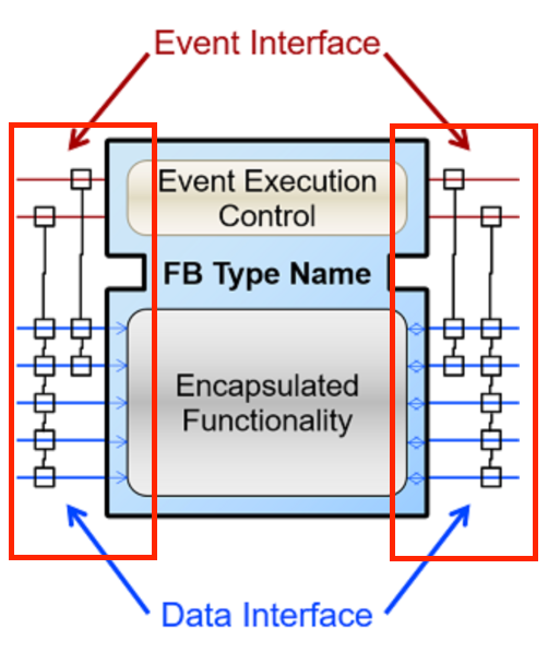
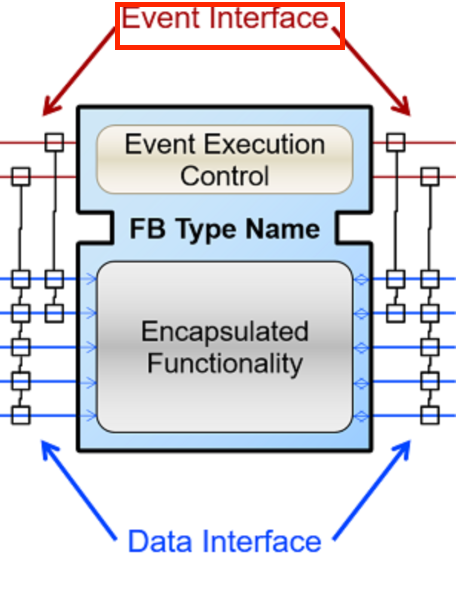
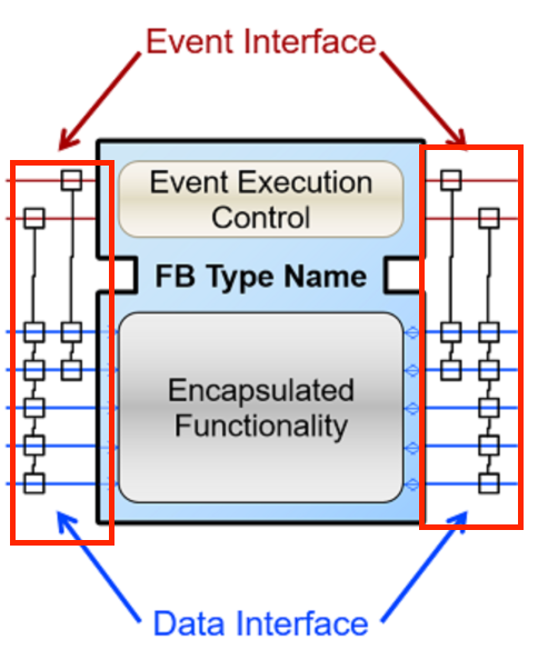
The Interface portion is divided into Event Interface and Data Interface. The red, upper part is the Event Interface and the blue, lower part is the Data Interface.
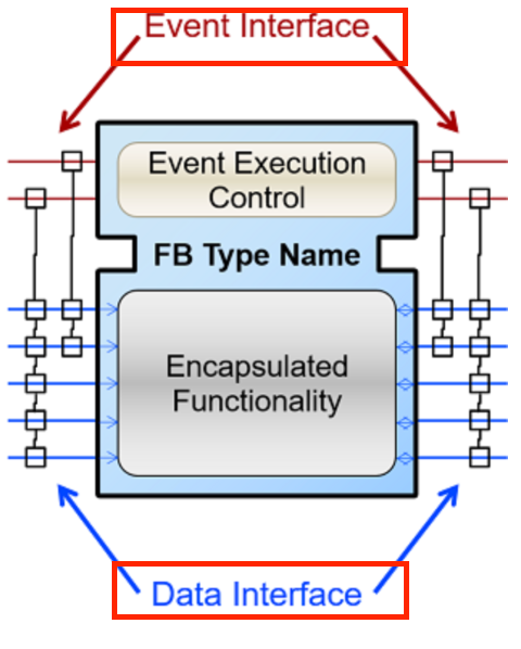
Event Interface
Event Interface triggers a function in the FB and passes the necessary data input inside the FB.It is important to note that Event Interface and Data Interface are not 100% compatible, so the possible share connections are limited.
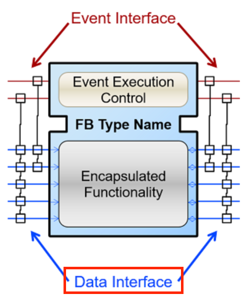
Data Interface
The data interface is also divided into output (FunOut) and input (FunIn).
An output (FunOut) is an input that is connected to the next FB.
Input (FunIn) is the data received from one previous FB or State.
Flag
Did you notice that Inteface’s Pin has lines and little squares?
When Event Input and Event Output are connected in this way, it is possible to define what data is updated when an Input/Output Event occurs.
So, the Function Block’s behavior depends on ECC>ECC has its own state>Event received>and only the algorithm encapsulated by the Event and the current state is executed.
Internal Sequence
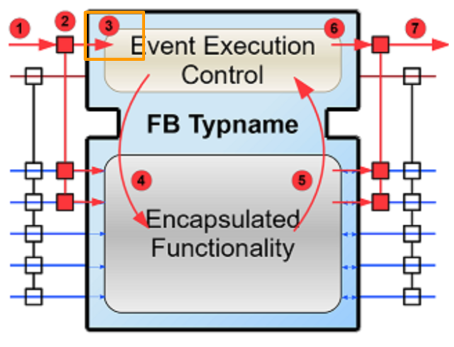
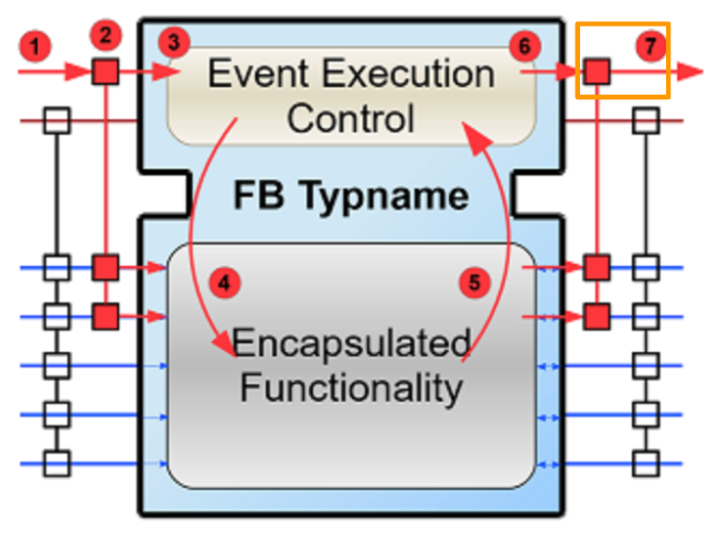
After explaining the Function Block Interface of IEC61449, let’s see the order of actual FB events are executed when they come.
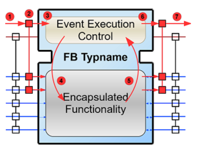
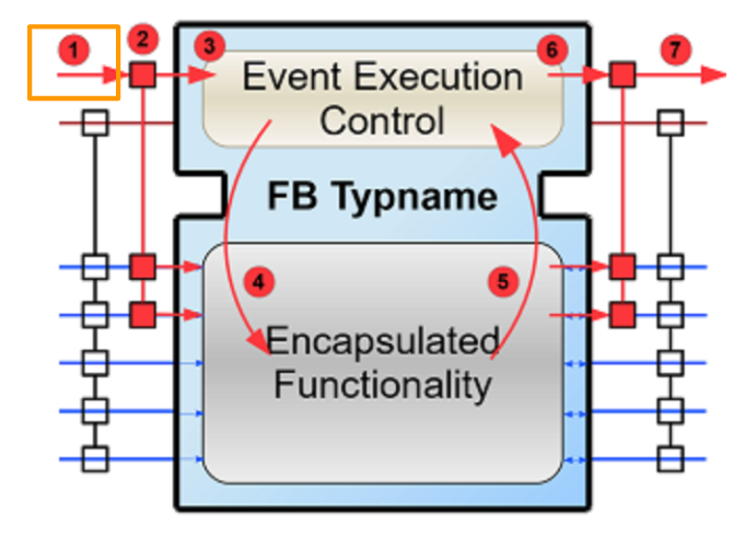
Step-1 Events arrives
The first event arrives at FB.
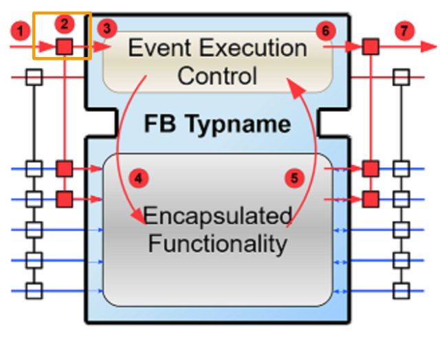
Step-2 Refresh Data
Update the data attached to the corresponding Event.
Step-3 Passed to ECC
Pass events to ECC (Event Execution Control).
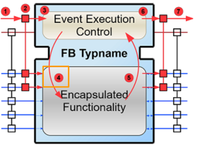
Step-4 Trigger
Trigger the internal functions inside your block.
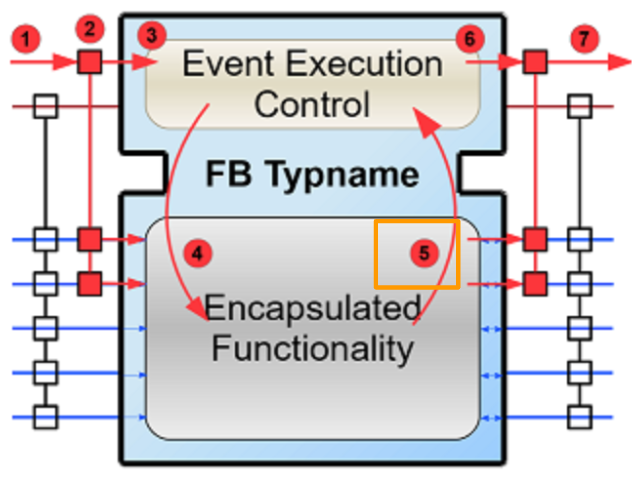
Step-5 Finish and Provided
The internal function ends and provides new Output data.
Step-6 Refresh Output
The FB will update the output associated with the corresponding Event.
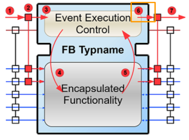
Step-7 Event Output
Output Event is output.
Configuration Example
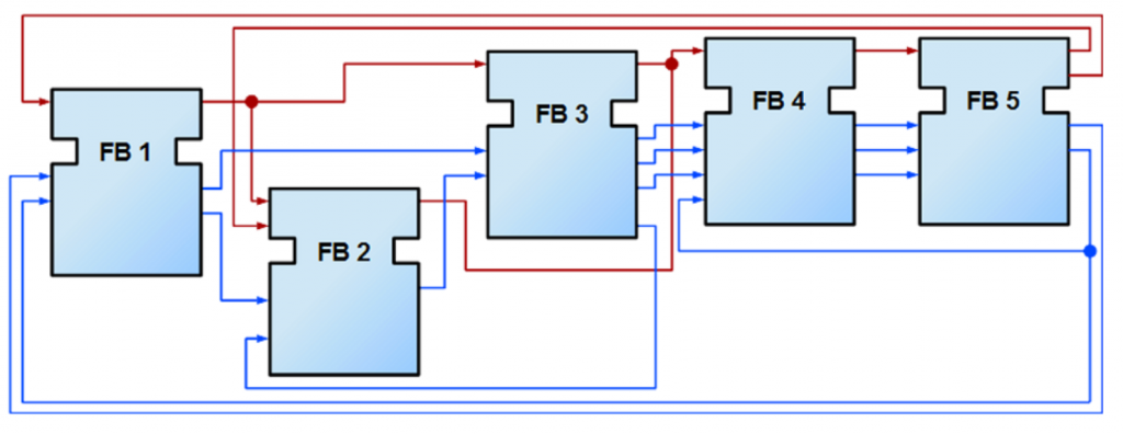
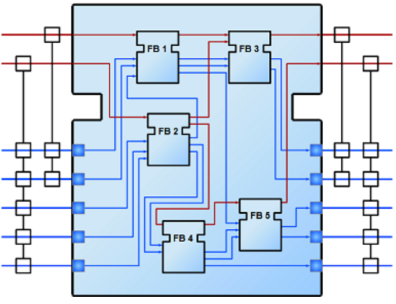
Because the standard allows for modeling of distributed systems, applications do not need to run on just one device. Instead, they can be partitioned and deployed to multiple devices (PLCs). Many applications can be prepared and distributed across many devices.
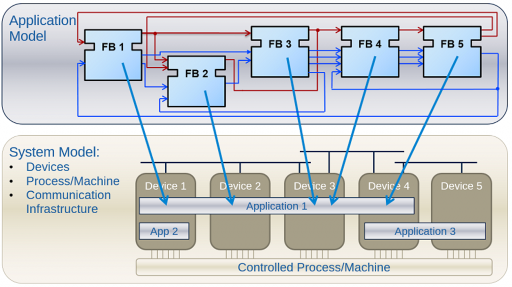
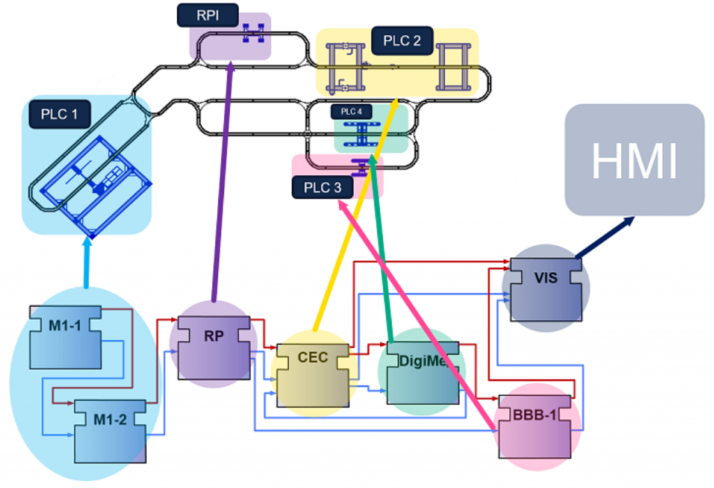
In fact a System using IEC61449 might look like this. Various PLCs are connected by lines, and Function Blocks are created in them. (This is just a reference diagram, so it does not show, for example, what to do if there is a connection problem or how to access hardware inputs/outputs.)
Types of Function Blocks
IEC 61499 defines three types of FBs that can be used when developing applications:
Basic Function Block (BFB):
It is the most used component of IEC61499.
The BFB is further divided into two parts.
- Execution Control Chart(ECC)
- You can use this component to define a State machine; ECC will decide which algorithm to run based on the state and input events.
- Algorithms(Alg)
- Algorithm is used to create the control part of the application using the programming language and other languages defined in IEC 61131.
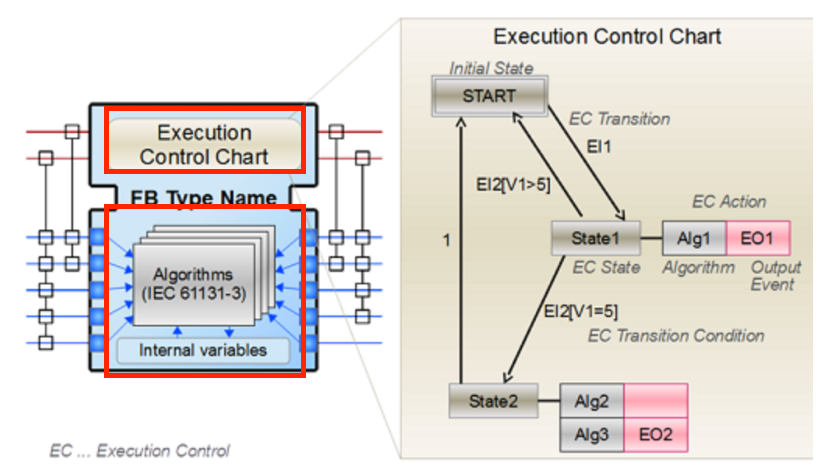
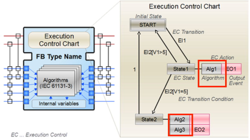
The figure below shows a simple BFB structure.
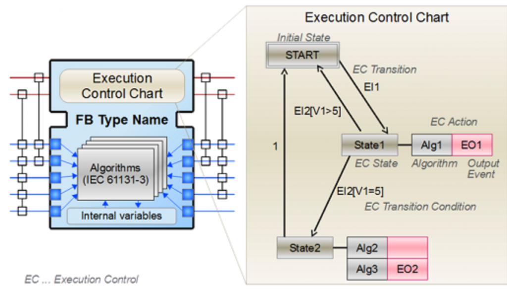
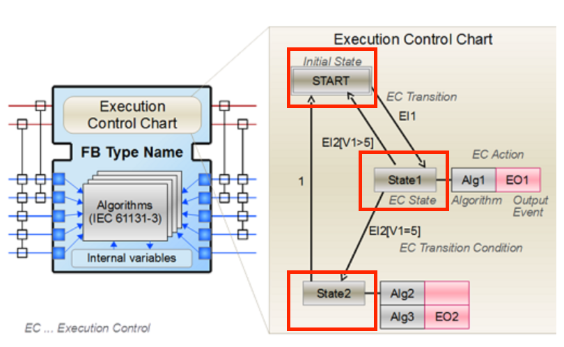
The gray color is the state box, and in the figure below, there are three boxes: START, State1, and State2.
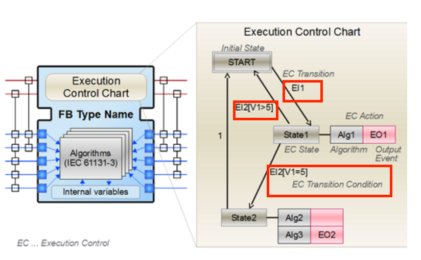
And it is a condition for transitioning states such as EI1 and EI2.
For example, it would be easy to understand that EI2 moves from State1 to State2 when V1=5.
The Pink Boxes of EO1 and EO2 are event outputs that are triggered when the corresponding state is transitioned.
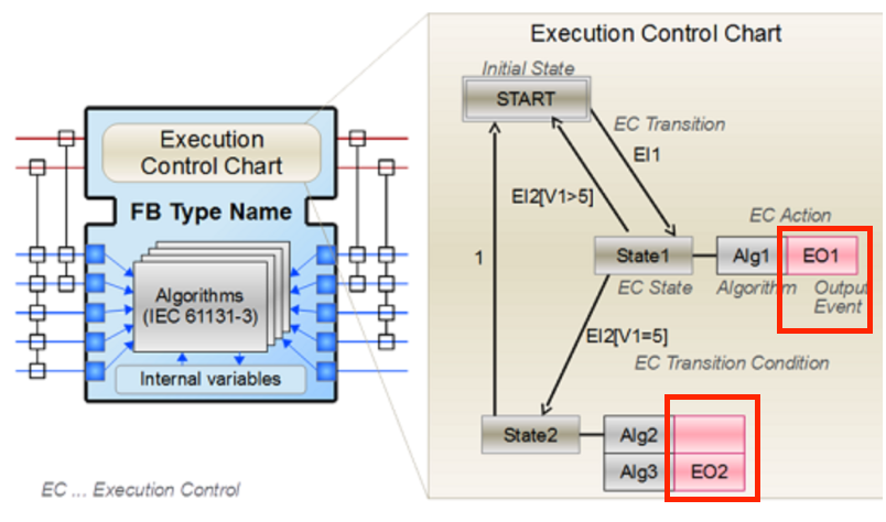
For example, if an EI1 event arrives when the FB is in START state, the FB jumps to State1, executes Alg1, and outputs an EO1 event.
The gray boxes (Alg1 to Alg3) in the ECC are the algorithms encapsulated within the function block.
Composite Function Block (CFB)
The CFB is an image of an internal network of multiple FBs.
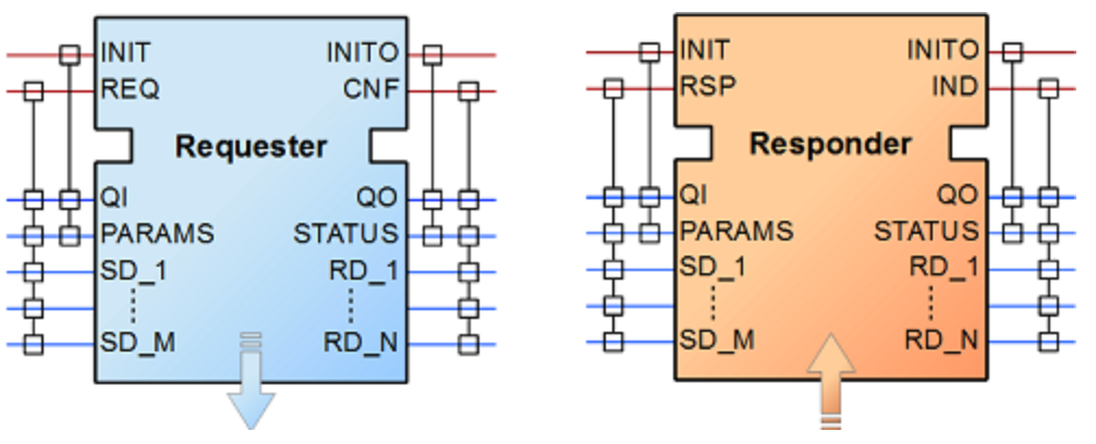
Service Function Block (SFB):
SFB is the FB needed to access a specific piece of hardware (e.g. access Wago’s IO Module via K-Bus) and the same application can be deployed on multiple devices.
SFBs are used for things that require direct platform access, which BFBs and CFBs cannot do. This type of FB can be triggered by hardware as well as by incoming events. So, the responder FB should be understood as triggering an event each time a packet arrives.
4diac Framework
Applications developed under IEC 61499 must use Function Blocks (FBs) to implement the logic from creating and defining FBs to actually controlling physical objects.(It is an IDE)
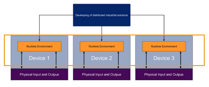
In addition, Runtime is required to actually run the application.
As will be mentioned in the future environment construction, you can actually select devices for mapping Function Blocks, and the IDE can function to update those programs all at once.
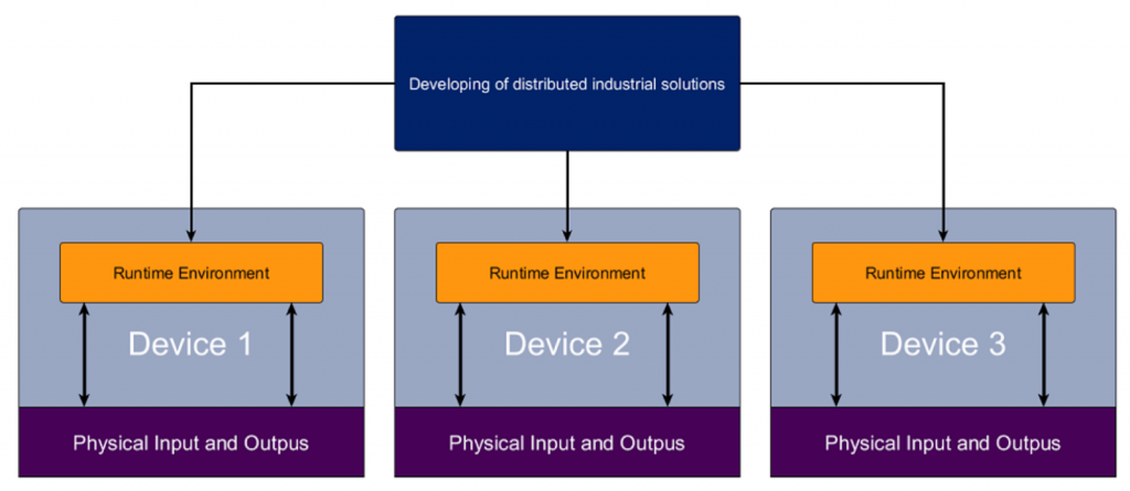
The IDE will be a tool that allows you to create FBs and connect each Runtime.
The Runtime Environment indicates actual devices such as PLCs, control hardware, Raspberry Pi, etc. These devices need to run the mentioned Runtime environment. It receives information from the distributed system, creates a network of FBs, executes them, handles event processing, etc. In addition, the devices typically have a runtime environment accessing the hardware inputs and outputs.
Components of Eclipse 4diac
Eclipse 4diac provides two main components for developing and running distributed control systems compliant with the IEC 61499 standard.
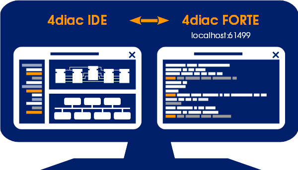
4diac FORTE
4diac FORTE is an IEC 61499 runtime (C++ implementation) that executes IEC 61499 FB networks on small embedded devices. It is important to note that 4diac FORTE is usually used on top of a real-time OS. And it has been tested on several different operating systems, including Windows, Linux (i386, amd64, ppc, xScale, arm), NetOS, eCos, Hilscher’s rcX, vxWorks and freeRTOS.
4diac IDE
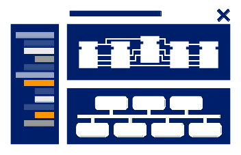
4diac IDE is an integrated development environment based on the Eclipse framework (Java) and provides an engineering environment for the IEC 61499 standard. 4diac IDE can be used to create FB applications, configure devices and perform other tasks related to IEC 61499. IEC 61499.
Applications developed in the 4diac IDE can run 4diac FORTE (Runtime) and other IEC61499 compliant Runtime.
Play with Windows
We will now experience IEC61499 in action using 4diac from a real Windows environment.
Download
Please download the 4diac IDE and Runtime in the Windows Version.
https://www.eclipse.org/4diac/en_dow.php
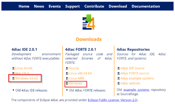
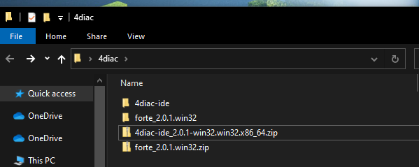
Please unzip these 2 files.
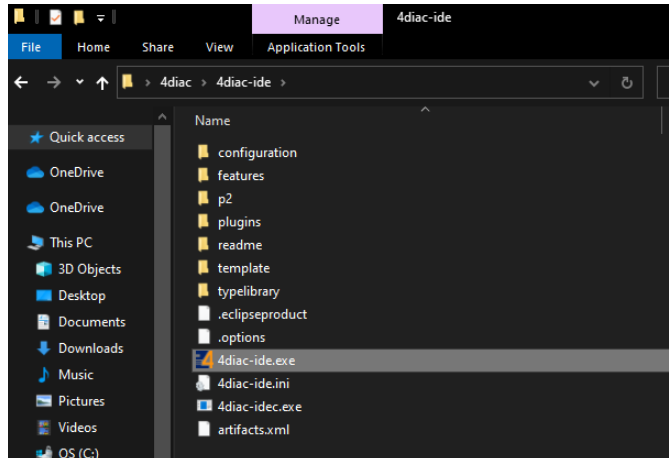
Start the IDE
Double click the 4diac-ide.exe to launch the IDE.
just a second.
Configure your Workspace location and Launch the 4diac IDE.
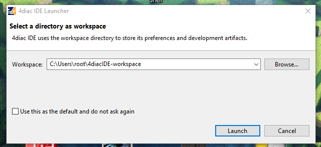
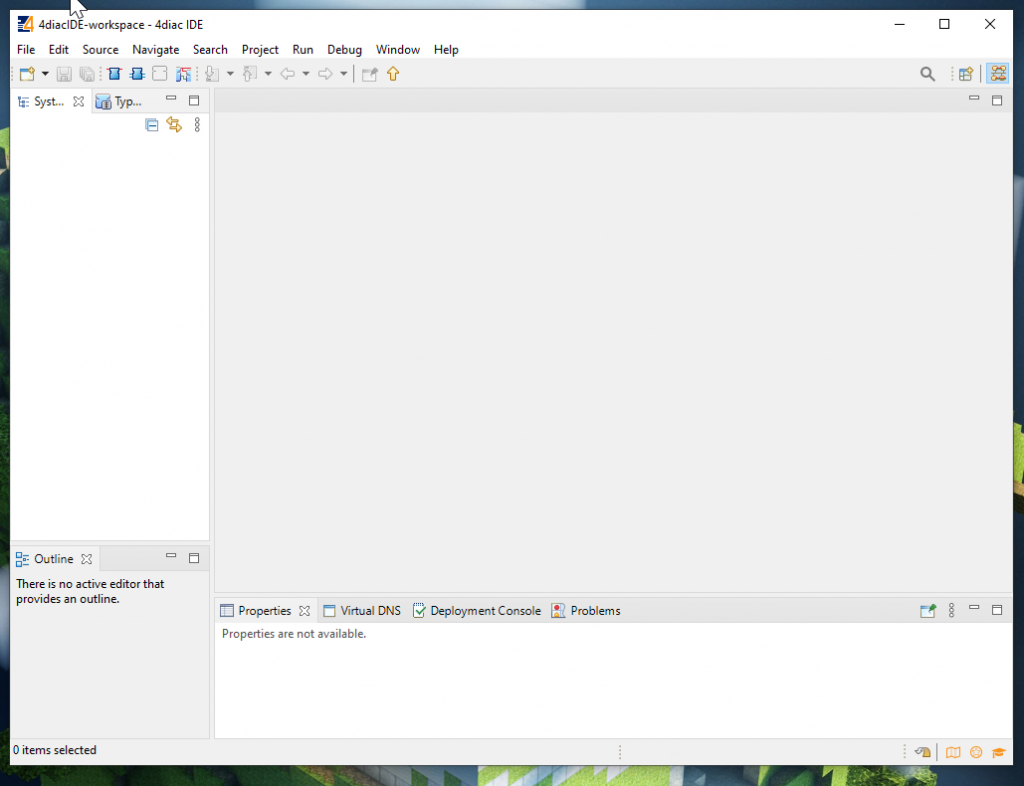
Done! IDE is Launch.
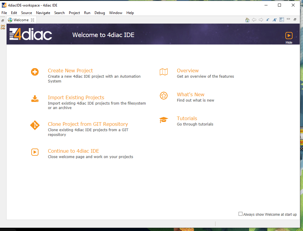
For the next fastly startup, check on the ”Always show Welcome at startup” option and press Hide.
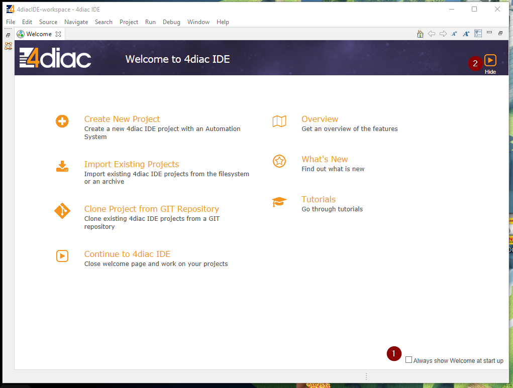
Done! IDE is Launch.
Configure Runtime
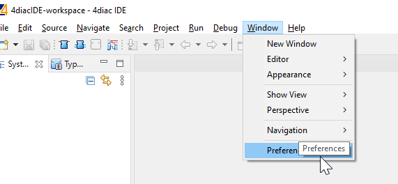
Then we can configure the Runtime by clicking Windows>Preferences.
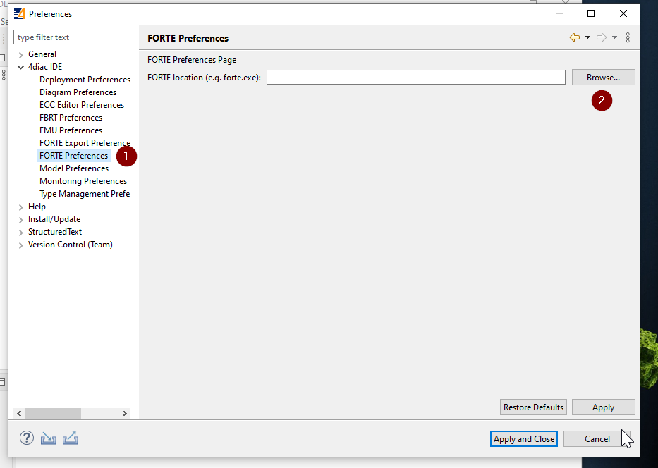
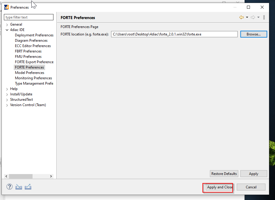
Open 4diac IDE>FORTE Preference and press the Browse button in the FORTE location.
Choose the ”forte.exe” that unzips from ”forte_2.0.1.win32” and Open.
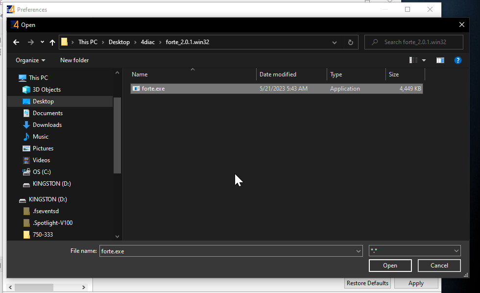
Apply and Close to save the settings.
Start new Project
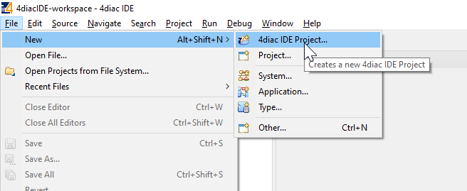
Go to File>New>4diac IDE Project to create a new project.
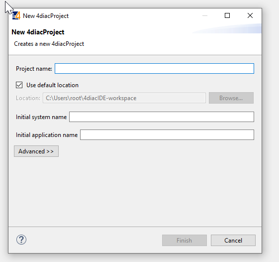
Enter your project name and press Finish to create a new project.
Done!A new project is created.
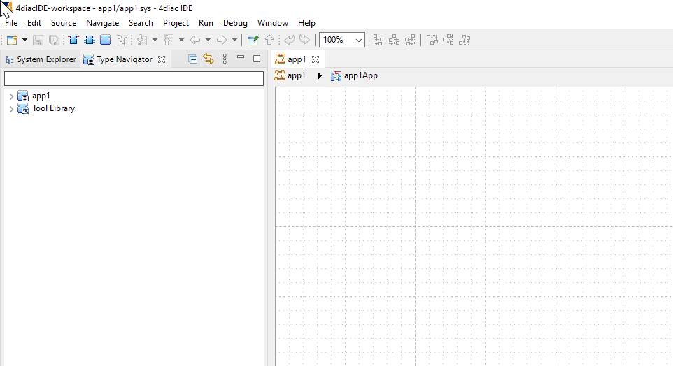
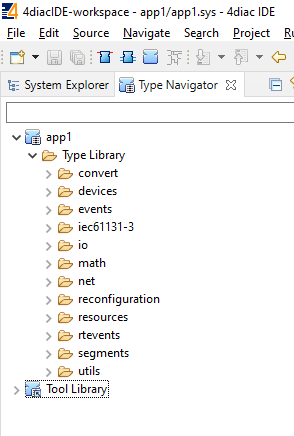
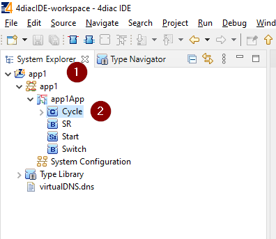
All libraries can be viewed in the Type Navigator.
Create Program
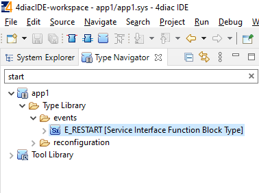
Now we may create a sample program.Go to Type Navigator>search “Start and E_RESTART FB is displayed.
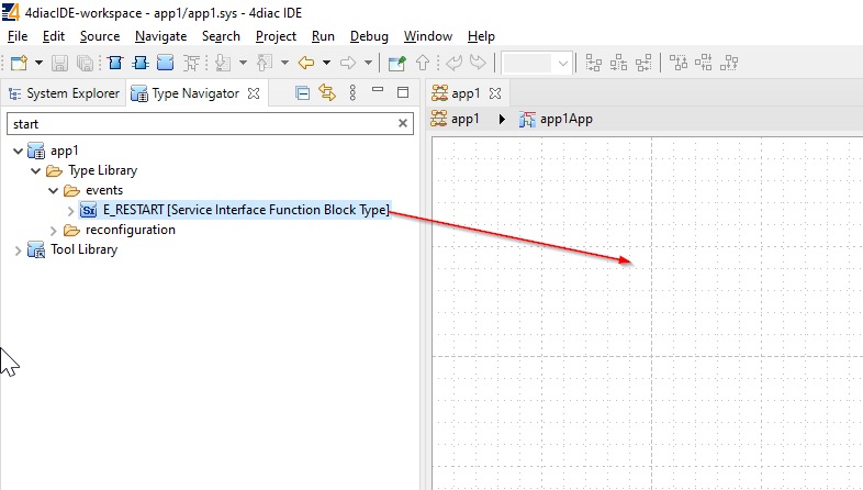
Please drop the E_RESTART FB into the Project area.
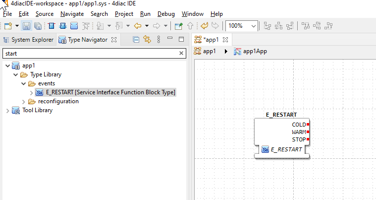
Done!E_RESTART FB is inserted.
You can change the Instance Name by opening the Properties of FB.
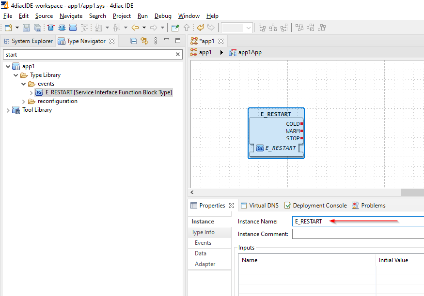
The Instance name of E_RESTART FB is changed to “Start”.
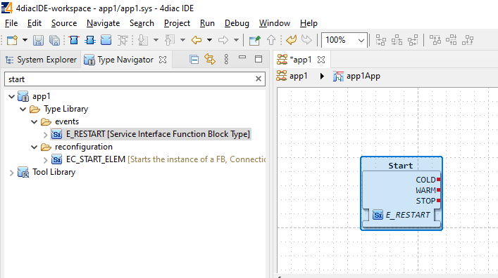
Use the same operation to search E_CYCLE FB and Drop into your Application area.
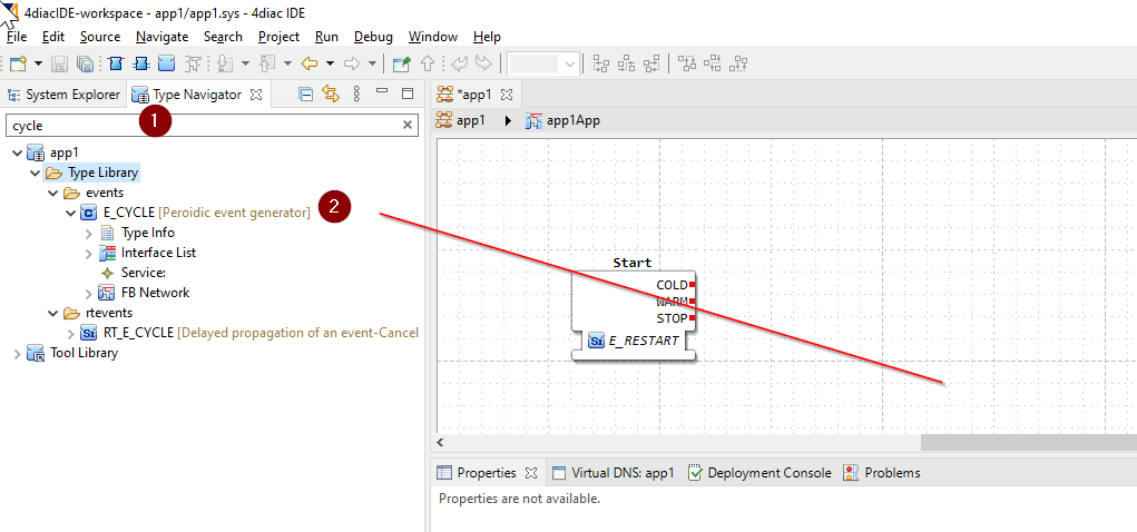
And you can check the Interface List of your FB.
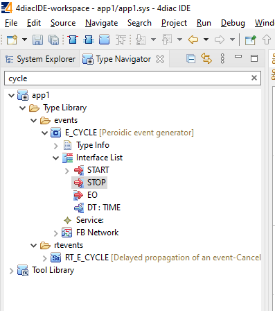
As first described in the Interface of FB, the red color is the Event Interface; let’s connect the COLD and WARMTH EVENT of Start with the START Event input of E_CYCLE.
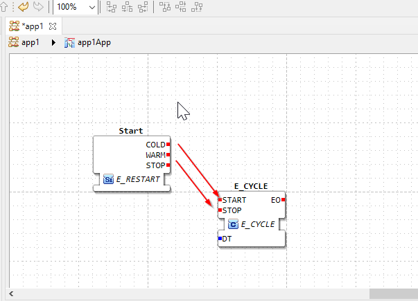
Just like this.
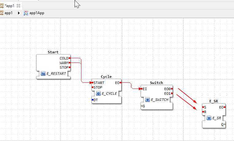
Add E_SWITCH FB in the same way and connect the Event output of Cycle FB with the Event input (EI) of Switch FB next.
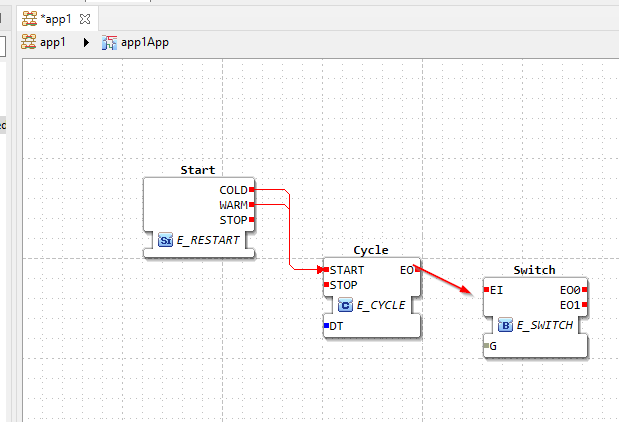
Now we can connect the EO of Cycle (DT of E_CYCLE FB, i.e., the Trigger time of that E_CYCLE can be set from the Data Interface) to the FB Event input of E_SWITCH.
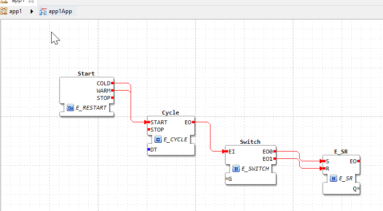
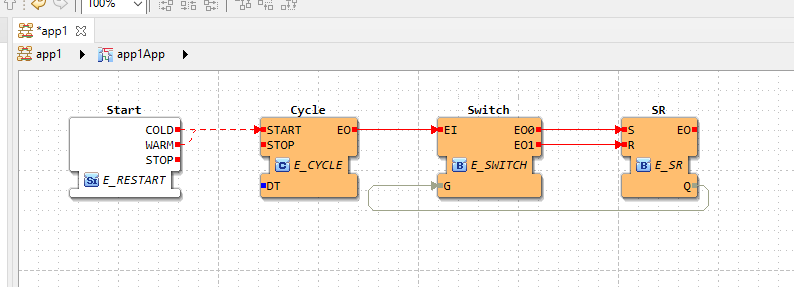
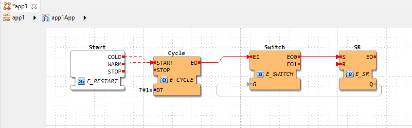
Finally, add FB E_SR and connect Switch EO0 and EO1 (Event outputs 0 and 1) to Event inputs S and R of E_SR.
Done!
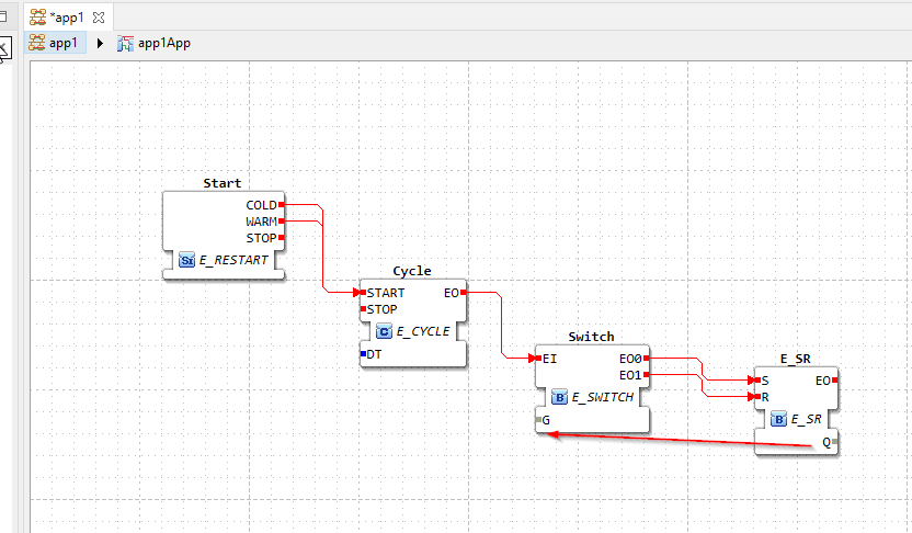
The last step is to Feedback the Data Interface Feedback of Q to G of Switch FB.
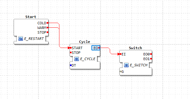
Lines between FBs can be adjusted.
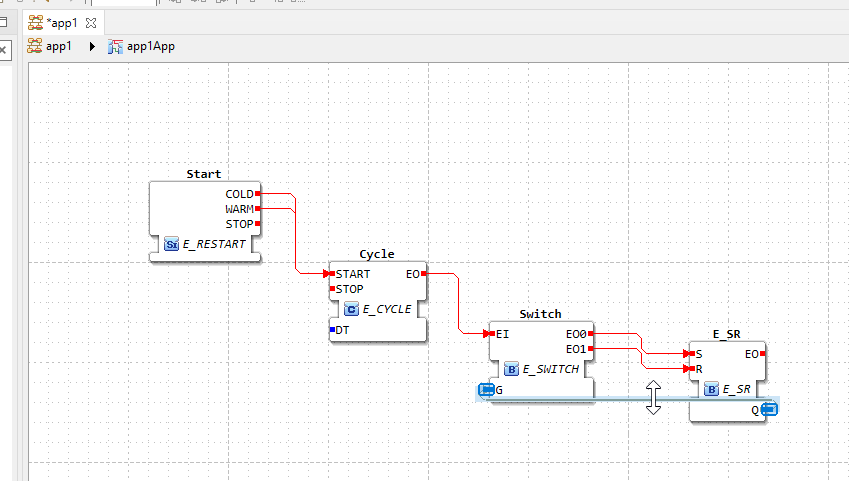
just like this.
See Source Code
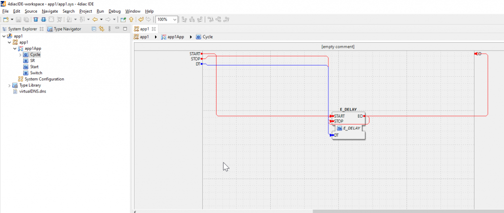
You can check the Source Code for each FB by double click on Cycle FB.
You can check the internal circuit of E_CYCLE.
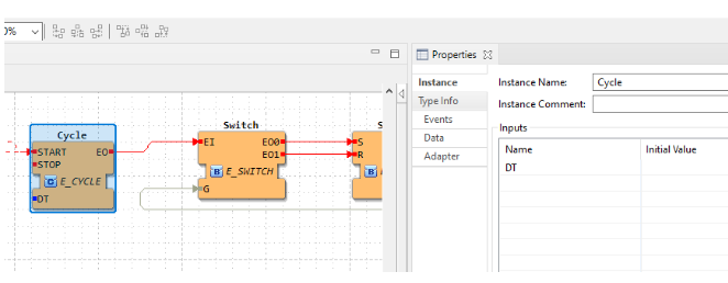
FB Properies
As mentioned before, you can configure detailed settings for each FB from Properties. If you do not see the Properties screen, click on Windows>Show View>Properties.
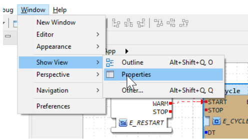
Properties of the selected FB can be listed in this way.
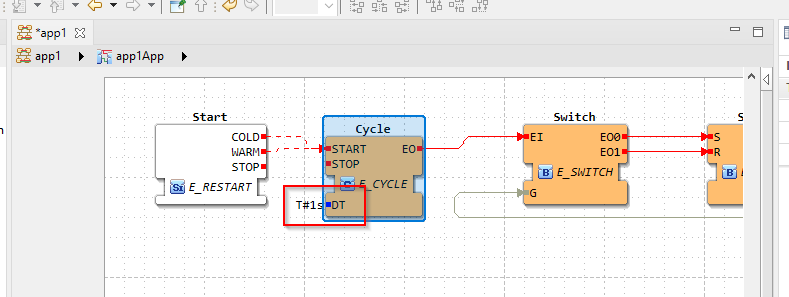
This time we will set the initial value of Data Interface DT of FB CYCLE ,by click on the Field of Initial Value and put T#1s here.
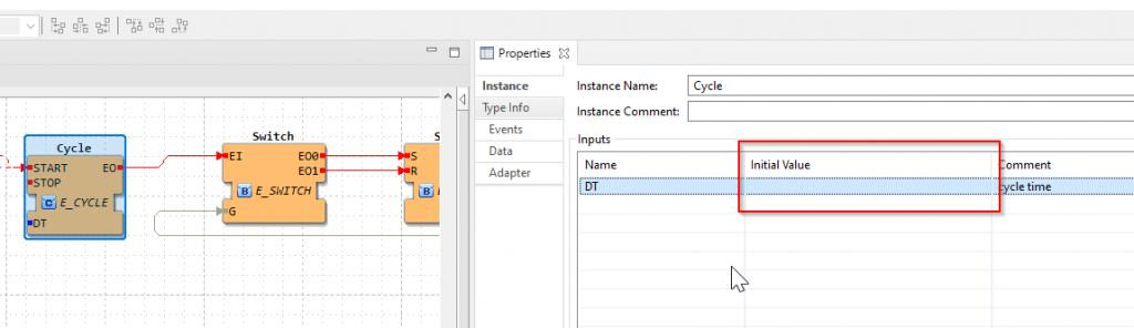
DT is now T#1s and FB_Cycle outputs EO (Event output) every second.
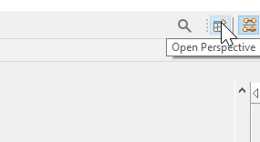
Start Runtime
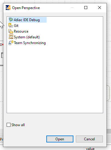
Click Open Perspective to launch Runtime.
Select 4diac IDE Debug and Open.
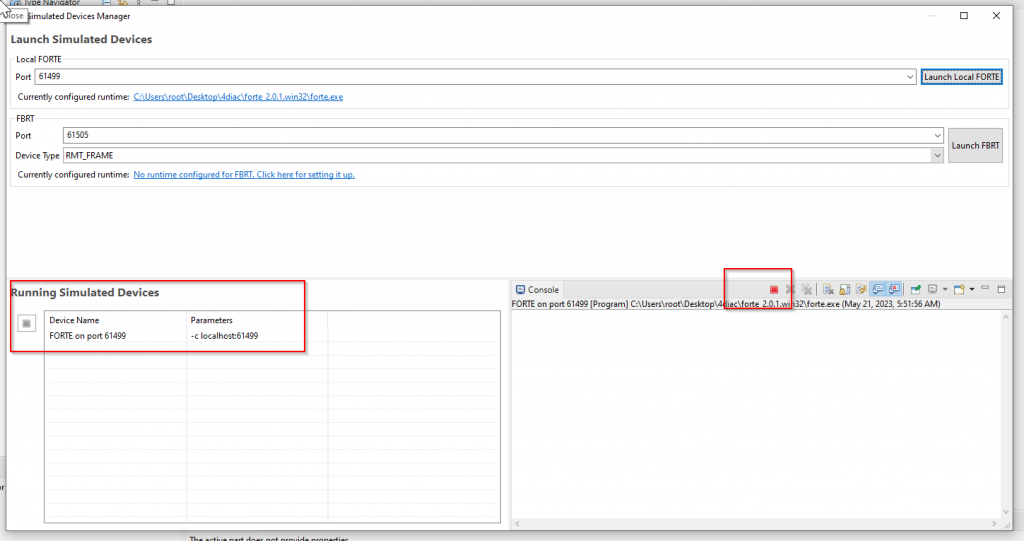
Next, open Debug>Open Simulation Devices Manager.
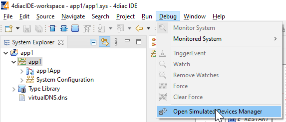
Simulation Devices Manage screen is shown.
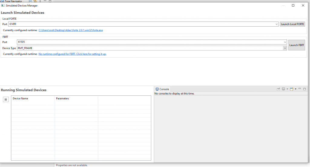
Click the Launch Local FORTE to start the Runtime.
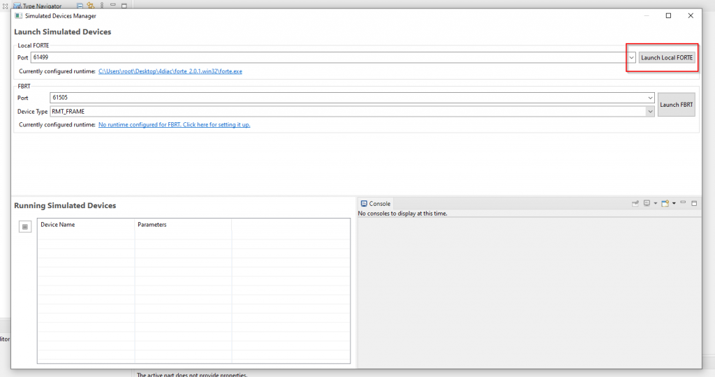
FORTE is running now.
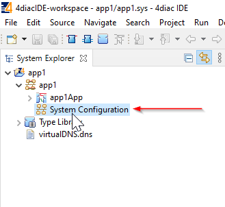
Hardware Configuration
Click on System Configuration and add the FORTE Runtime that was just started.
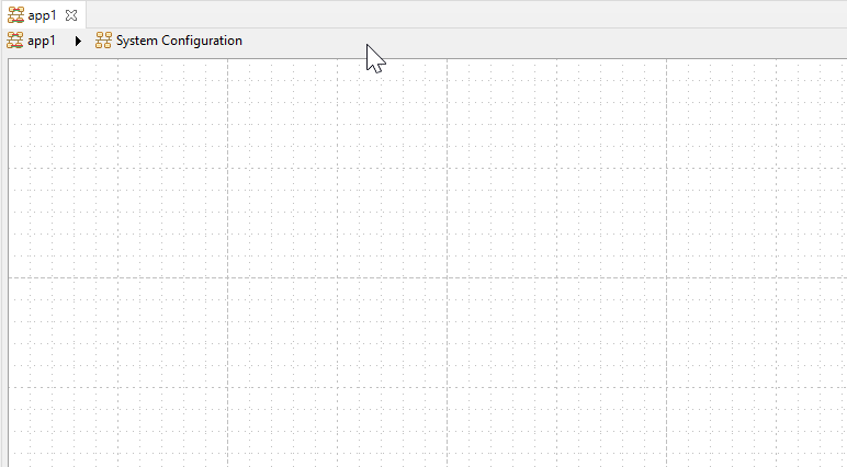
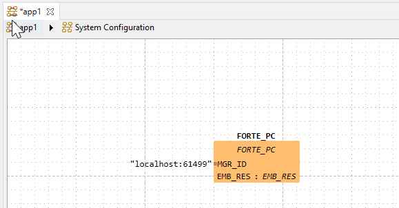
The System Configuration screen appears.
Add FORRE_PC from Palette on the right.
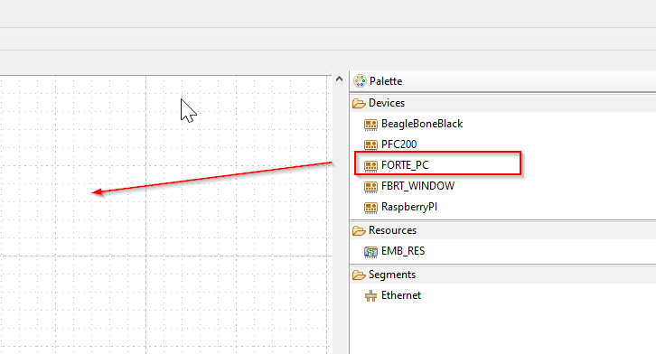
FORTE_PC has been added. The current port for FORTE_PC is 61499, but if you set a port other than 61499 in the “Start Runtime” step earlier, please adjust this port as well.
Mapping
Link the FB to the Local FORTE you just added. For example, right click on Cycle FB>Map To. >FORTE PC>EMB_RES.
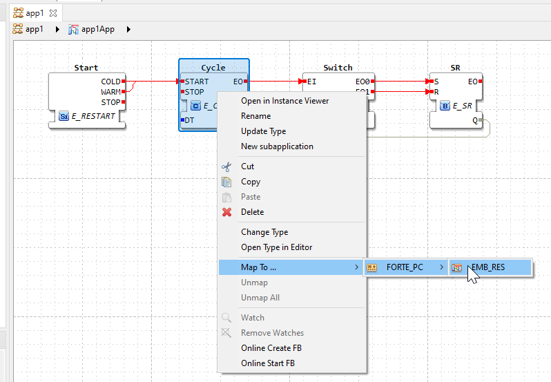
Mapped FBs will be orange.
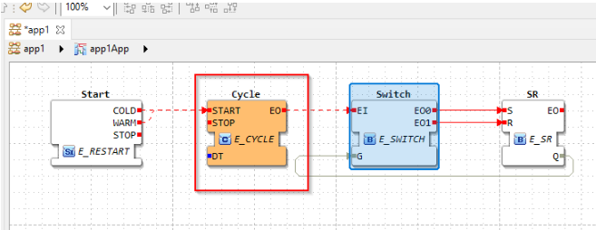
3 FBs are Mapped.
Deloy
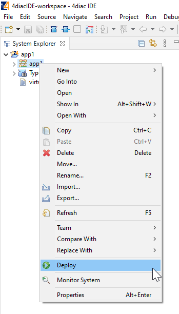
The last step is to Download the application to the device. Go to Project>Right click>Deploy.
Watch
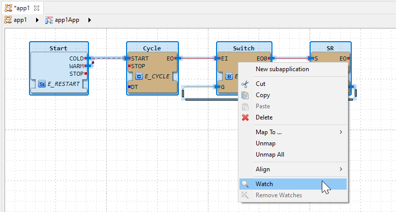
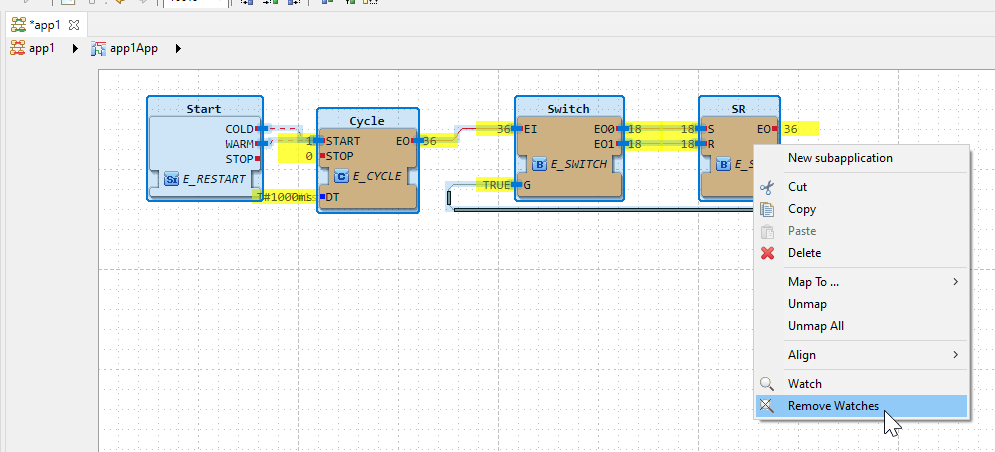
Select the Block you wish to monitor>right click>Watch.
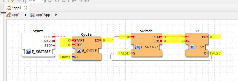
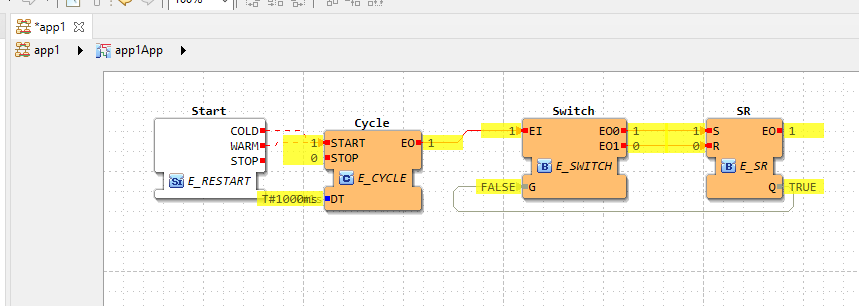
The current value of each FB was also displayed.
Right-click on the small yellow area at the Start of the Cycle (where the current value is displayed) > TriggerEvent.
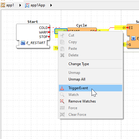
START=1, Cycle is started, and EO1 in SR repeats ON/OFF in 1s cycles.
If you want to exit the Monitor function, please right-click>Remove Watches.
Done.
Result
Here are the actual results.
コメント
Thanks for the info, it helped me broaden my horizons. unibet