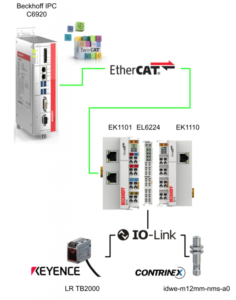
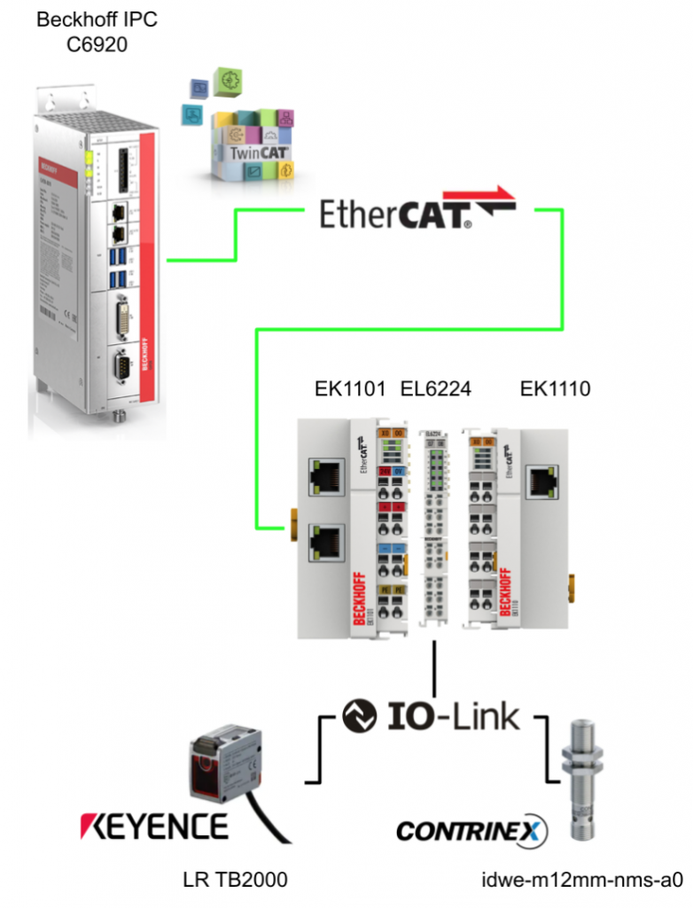
In this article, we will use Beckhoff’s EL6224 IO LINK Terminal to get data from IOLINK devices via EtherCAT. The IO-LINK devices used in the article are Keyence LR TB2000 and Contrinex IDWE-M12MM-NMS-A0.
Let’s Start!
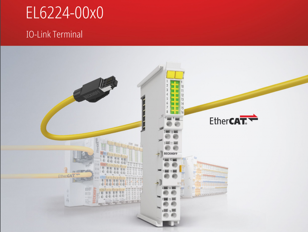
EL6224?
The IO-Link Terminal EL6224 is a device that allows the connection of up to four IO-Link devices. The EL6224 terminal is parameterized and configured via an EtherCAT master,
Parameterized information can be exchanged bi-directionally via the IO-Link connection.
Parameterization of IO-Link devices with service data can be done from TwinCAT via ADS or with the integrated IO-Link configuration tool.
It communicates as needed with the connected IO-Link device, parameterizes the device, and changes the operating mode as needed.
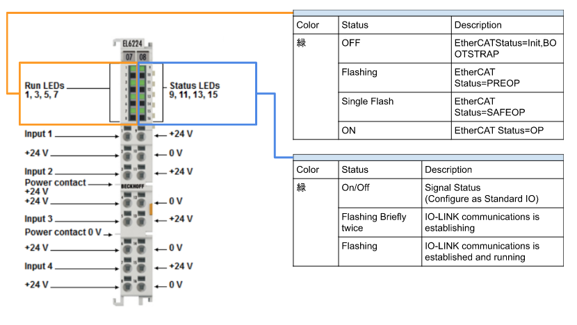
Layout
This is a Layout for EL6224.
IO-Link basics
IO-Link is a communication system for connecting intelligent sensors and actuators to automation systems.
The IEC 61131-9 standard specifies IO-Link under the name “Single-drop digital communication interface for small sensors and actuators” (SDCI).
Both the electrical connection data and the communication protocol are standardized and summarized in the IO-Link specification.
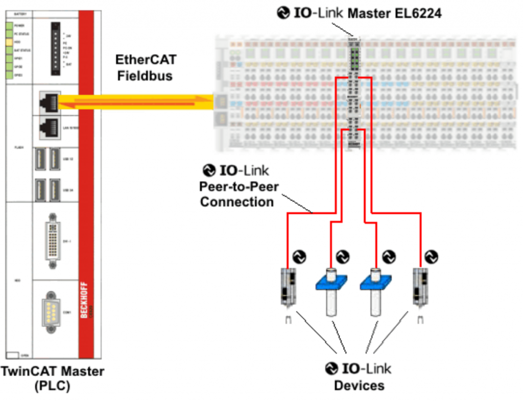
An IO-Link system consists of an IO-Link master and one or more IO-Link devices, i.e. sensors and actuators. The IO-Link master provides an interface to a host controller and controls communication with the connected IO-Link devices. The Beckhoff EL6224/EJ6224 IO-Link Master Terminal has four IO-Link ports. One IO-Link device can be connected to each of them. As shown in the figure below, IO-Link is not a fieldbus, but a Point to Point connection.
The Beckhoff EL6224 used in this project is subject to IO-Link Specification 1.1 for IO-Link master development.
Be careful!
IO-Link devices must be powered from the EL6224’s 24 V power supply; using a separate power supply may damage the IO-Link port.
Establishment of IO Link communication
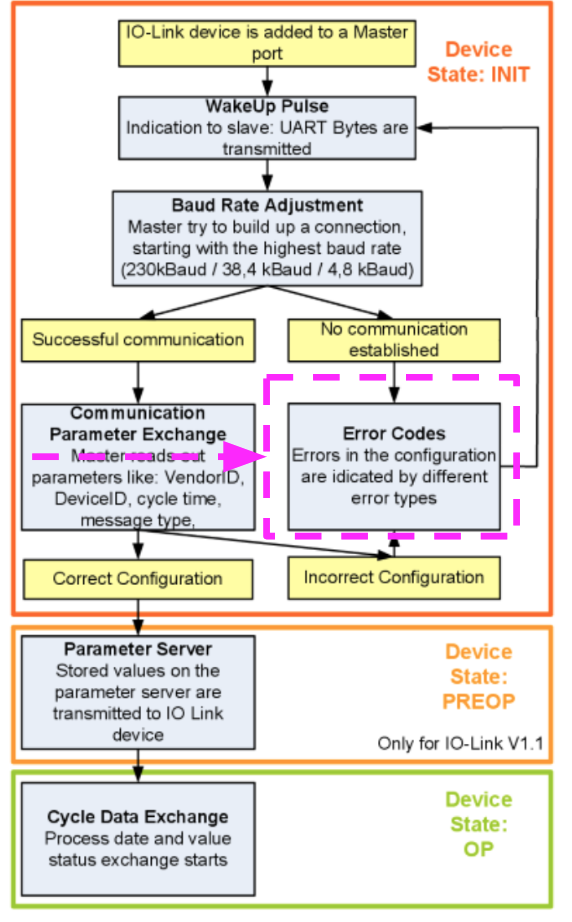
This is the establishment flow of IO-Link communication; System will follow this sequence to connect when the IO-Link Port is auto-scanned.
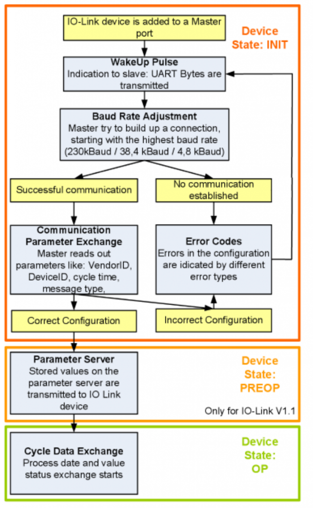
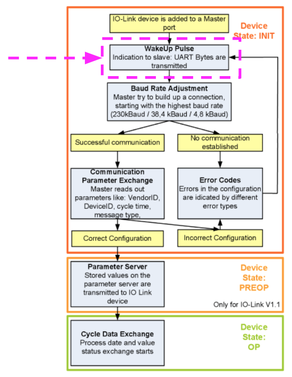
Wakeup Pulse
When an IO-Link device is connected to a Port on the EL6224, the master tries to establish communication, so the defined signal level (wake-up pulse) sends the device that says, “We are about to send a UART byte!”.
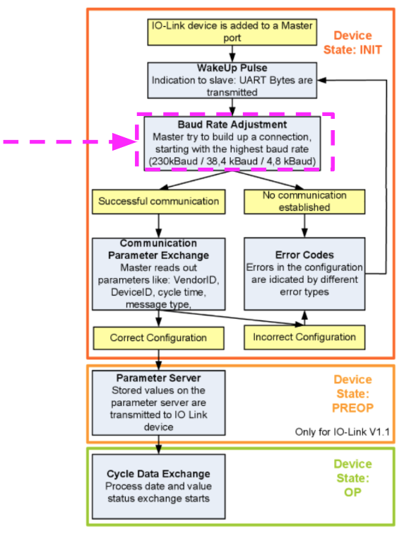
Baud Rate
IOLINK Master executes all Baud rates and starts communication from the fastest Baud rate among them (COM3=230 kbaud).(When the IOLINK Slave responds to the Wake up pulse in Step-1, the connection is successful.
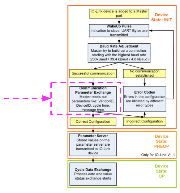
Communication Parameter Exchange
Next, IOLINK Master exchanges the basic parameters of Slave
- Vendor ID
- Device ID
- Process Data Length
- Telegram Type
- Cycle Time
and compare with the actual configuration.
Errors in Configuration
If the device could not be connected or the saved parameters are different from the loaded parameters、 an error is output.
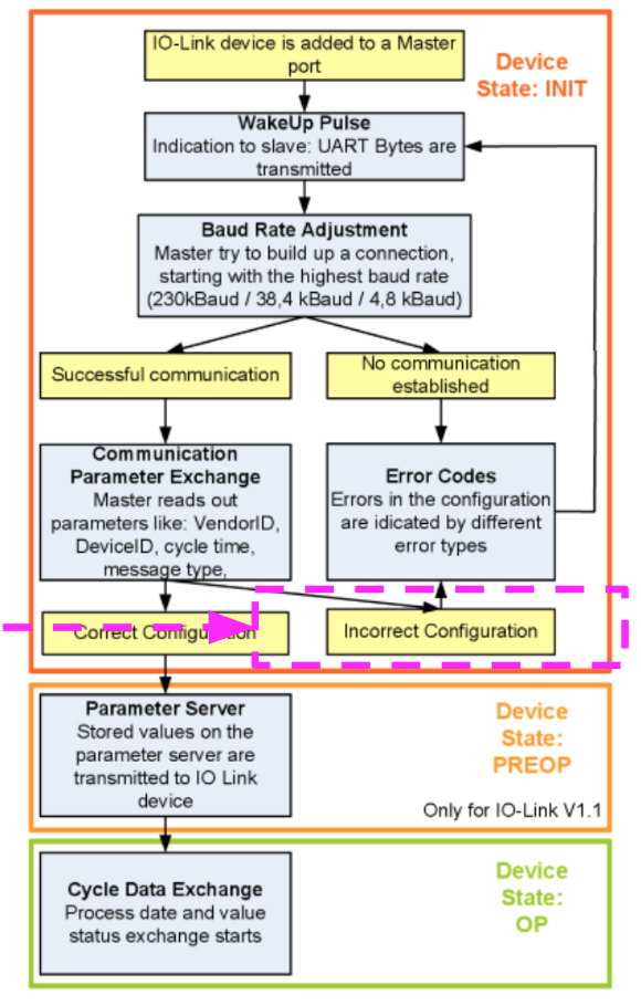
if Configuration is incorrect..?
If the stored and read parameters are different, the IO-Link device changes to the PREOP state.
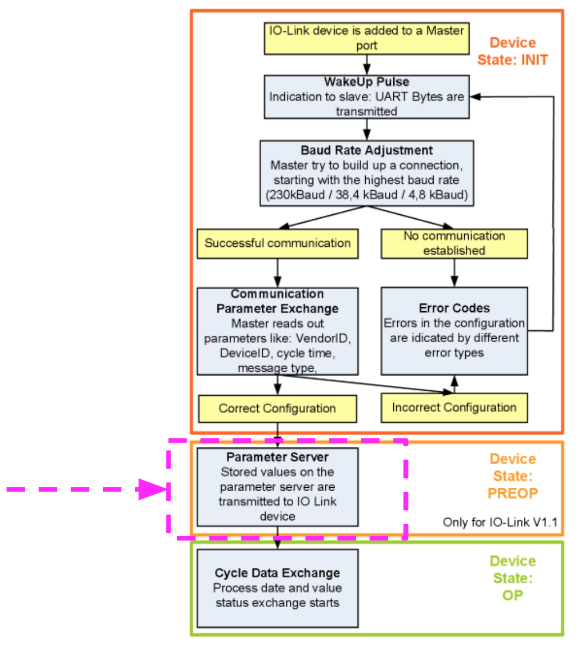
IO-Link device specification is V1.1
If the IO-Link device specification is V1.1, the parameter server is executed; if the IO-Link device is V1.0, the device is changed directly to OP.
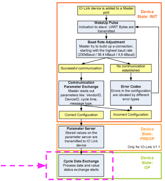
Finally
Finally, the cycle time is written and the device transitions to OP. The IO-Link master exchanges data with the IO-Link device in cycles.
Between TwinCAT..
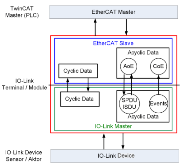
The Beckhoff EL6224 IO-Link master terminal is divided into two services.
- IO-Link master in relation to connected IO-Link devices
- Connection of EtherCAT slaves in relation to a PLC TwinCAT master
Basically, Cyclic and Acyclic data are exchanged.
- Cyclic Process data is accessed via PDOs
- Acyclic data is accessed via AoE
- Events are displayed in the System Manager history.
Implementation
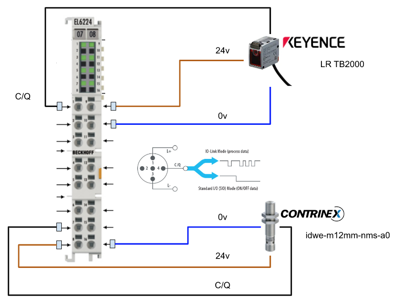
Here is a wiring diagram of the EL6224 Terminal and IO Link device.
Wiring
Configuration
Add EtherCAT Master
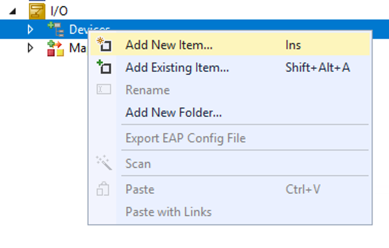
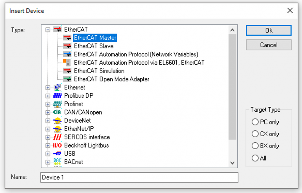
Add a new device at I/O>Devices>Add New Item.
Select EtherCAT>EtherCAT Master>Ok.
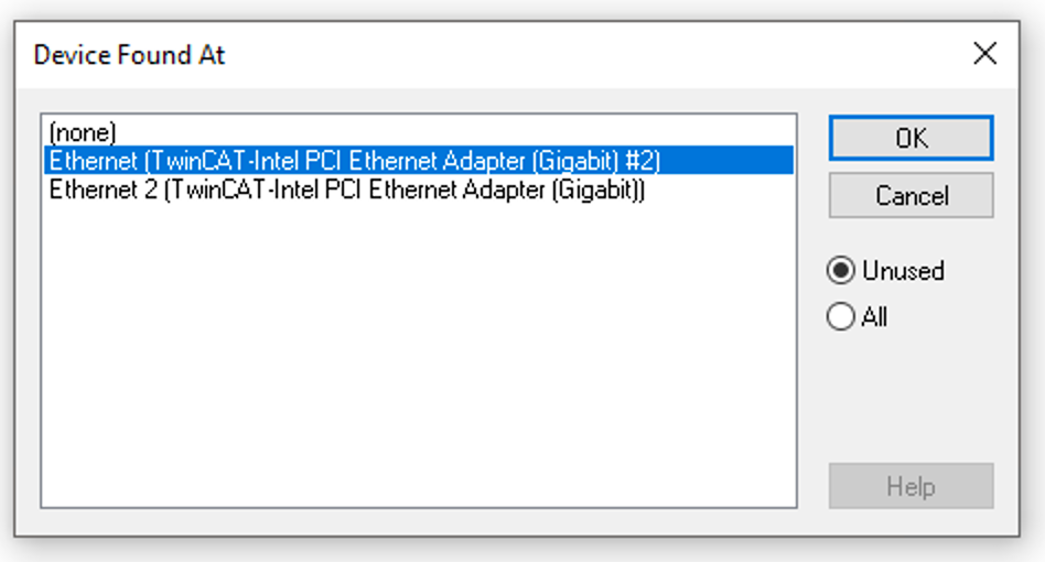
Select the LAN CARD of the EtherCAT Network to which you are now connected and press OK.
Add EL6224
There are two ways to add an EtherCAT Slave from TwinCAT: Manual or Auto-Scan.
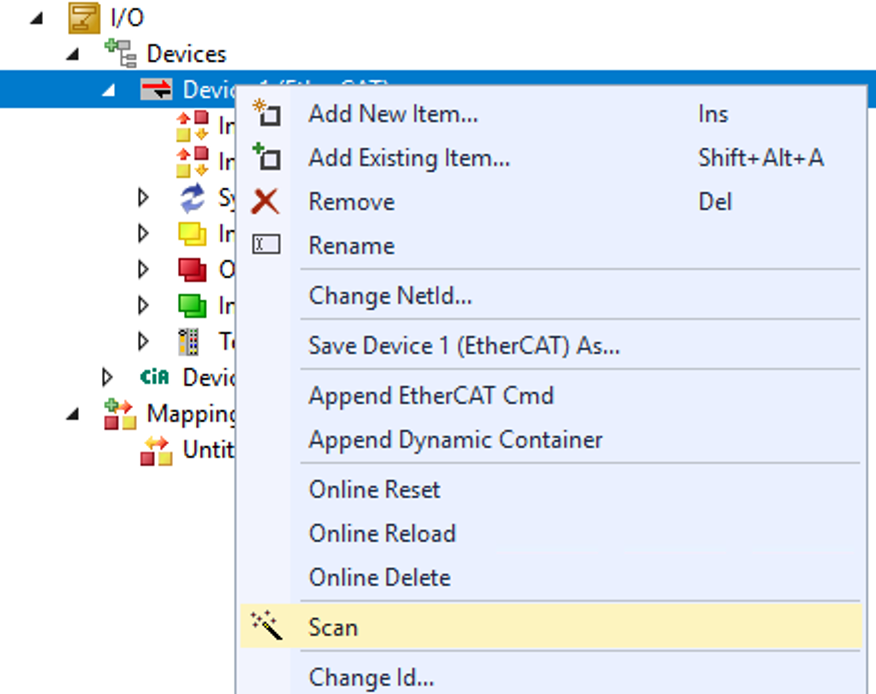
Scan
Next, go to EtherCAT Master>Right click>Scan and search for EtherCAT Slave.
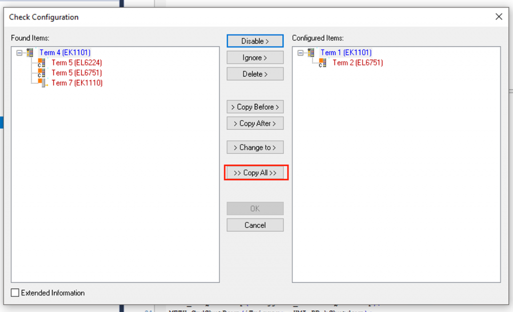
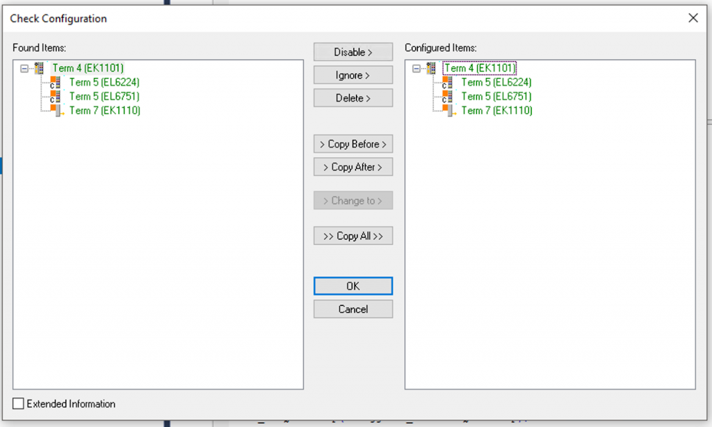
If the hardware configuration of the project differs from that of the actual device, TwinCAT can check the difference. In this case, TwinCAT uses Copy All to synchronize the configuration of the actual device with the project.
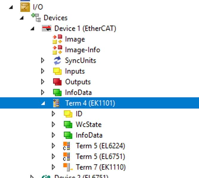
Done!
EL6224 has been added to the EtherCAT network.
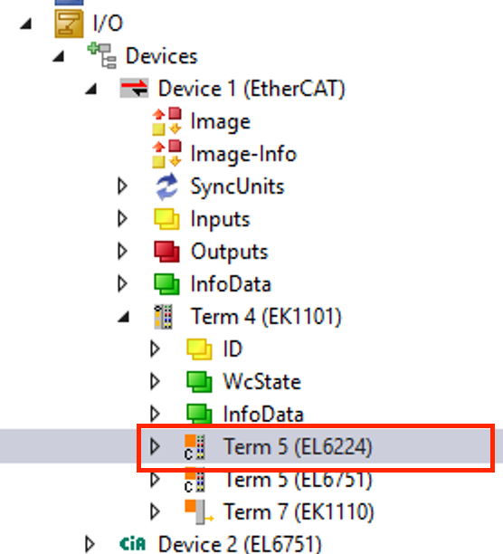
Configurate EL6224
Configure the settings for EL6224.
Port1
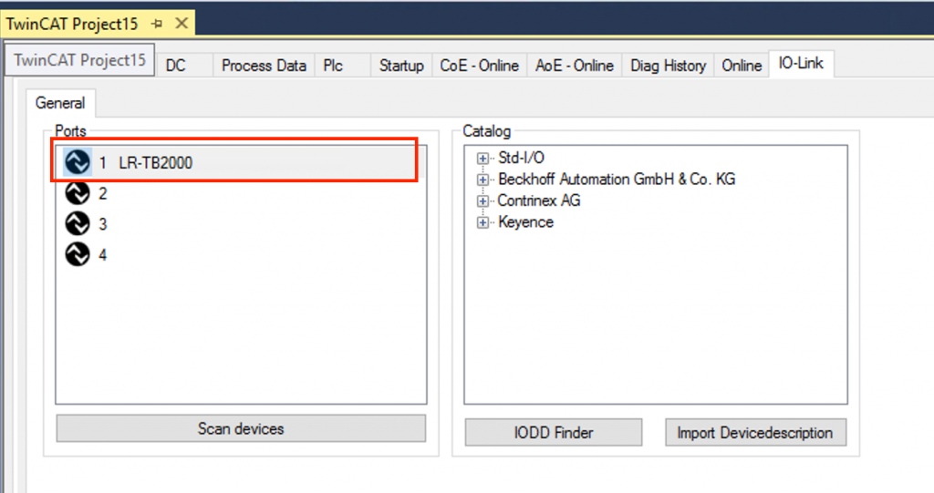
Open the Tab of IO-LINK. You can configure settings for each Port on this screen.
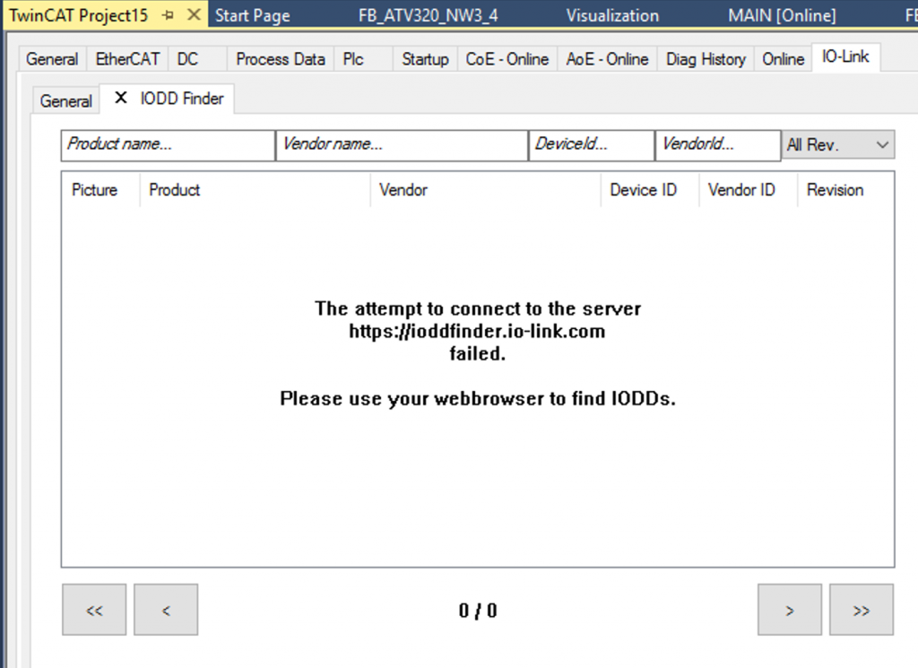
Let’s open the IODD Finder.
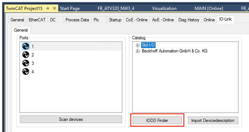
Although my IPC is not connected to the Internet right now, I can search for and install the IODD File directly into my project from this screen if there is an internet connection.
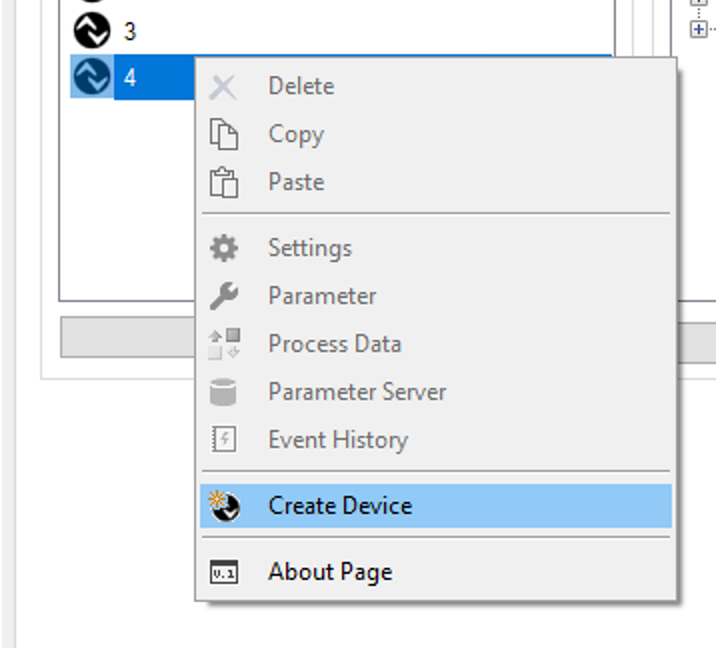
Let’s manually create a new IOLINK device by selecting Ports1 and right-clicking>Create Device.
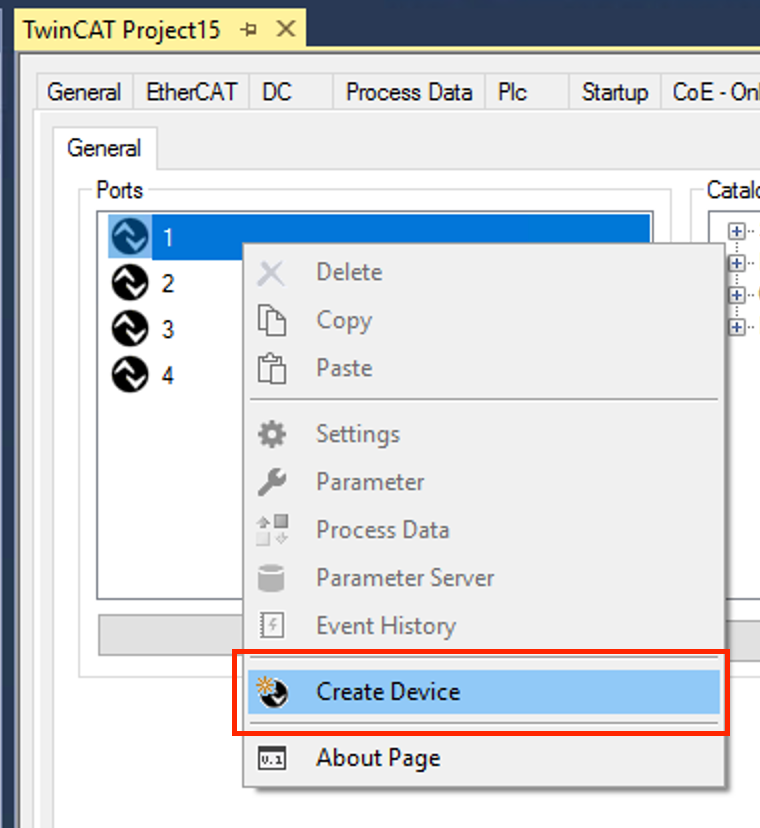
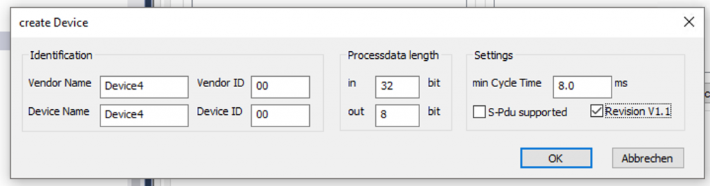
The Create Device screen appears.
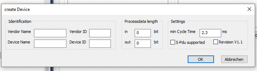
Please set the Vendor Name and ID as an easy-to-understand name, and Process length should be 16 Bit.
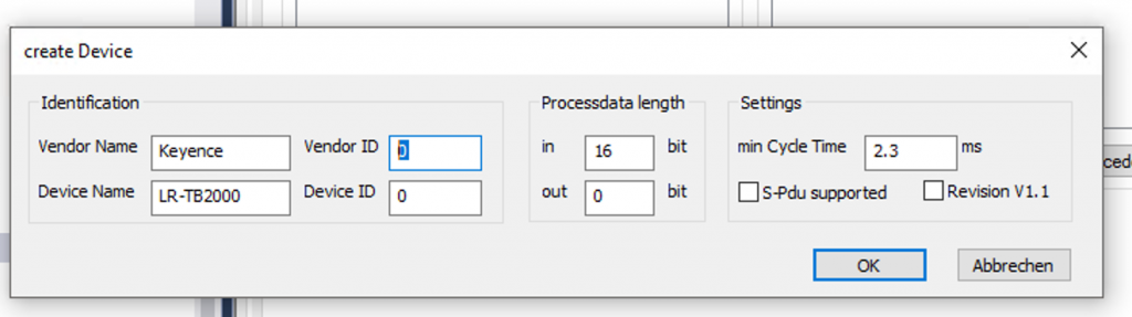
An IO-LINK device has been created on Port1.
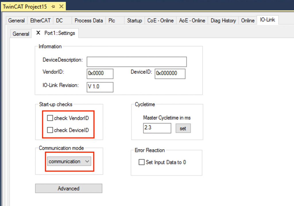
Right-click on the IO-LINK device you just created>Settings.
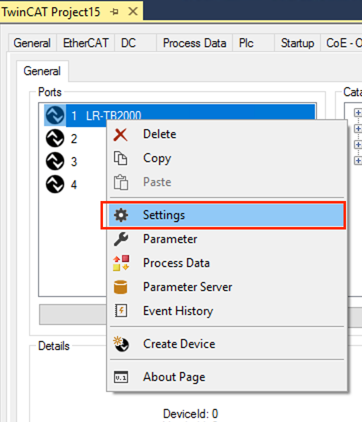
Check VendorIDとCheck DeviceIDのCheckBOXを外し、Communication modeをCommunicationに選択すればOkです。
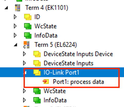
An IO-Link Port1 was automatically added to the EL6224 module and 2Bytes of Process data was defined inside.
Port4
Add Contrinex’s Idwe-m12mm-nms-a0 IO-LINK device to Port 4 in the same way.
In=32bit, Output=8Bit, and Min Cycle time is set to 8.0ms.
Add PLC
PLC>right click>Add New Item.
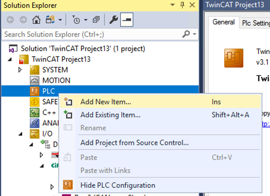
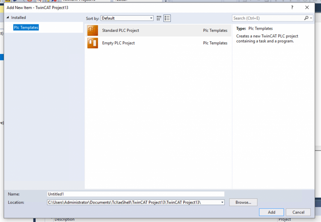
Add a new PLC project at Standard PLC Project>Add.
Program
FB_EL6751_Basic
This Function Block is used to get the EL6224 module’s DeviceStateInputs variable.
The DeviceStateInputs allows you to obtain the status of each Ports.
| FUNCTION_BLOCK FB_EL6224_Basic IMPLEMENTS ITF_EL6224_Basic VAR_INPUT END_VAR VAR_OUTPUT END_VAR VAR DeviceStatesInputs AT %I*:ARRAY[1..4]OF USINT; END_VAR |
METH_Port_OK
This Method takes the iPort number as a parameter and returns True if the current status is 3 (IO Link Port normal).
| METHOD METH_Port_OK : BOOL VAR_INPUT iPort : INT; END_VAR METH_Port_OK:=FALSE; CASE iPort OF 1..4: METH_Port_OK:=DeviceStatesInputs[iPort] = 3; END_CASE |
FB_LR_TB2000
Here is the Function Block for Keyence’s LR-TB2000.
iPortOK is an external input parameter to check if the Port is communicating properly.
| FUNCTION_BLOCK FB_LR_TB2000 IMPLEMENTS ITF_LR_TB2000 VAR_INPUT iPortOK :BOOL; END_VAR VAR_OUTPUT END_VAR VAR Inputs AT %I*:INT; Data :INT; END_VAR |
METH_Update
IO-LINK data will not be updated unless the Update Method is called.
| METHOD METH_Update : BOOL Data:=0; IF Prop_Enable THEN Data:=Inputs; END_IF; |
Prop_Distance:GET
If IOLink Port is OK for communication, 2Bytes distance data is updated.
| PROPERTY Prop_Distance : INT Prop_Distance:=0; IF Prop_Enable THEN Prop_Distance:=Data; END_IF |
FB_IDWE_M12MM_NMS_A0
Here is the Function Block for Contrinex’s IDWE_M12MM_NMS_A0 ‘s IOLINK device.
| FUNCTION_BLOCK FB_IDWE_M12MM_NMS_A0 IMPLEMENTS ITF_IDWE_M12MM_NMS_A0 VAR_INPUT iPortOK :BOOL; END_VAR VAR_OUTPUT END_VAR VAR //Link to Process Data input AT %I*:DINT; output AT %Q*:BYTE; END_VAR VAR StatusWord :BYTE; ScalingValue :BYTE; MesurementValue :INT; InputBuffer :ARRAY[0..3]OF BYTE; END_VAR |
METH_Disable
This method disables Contrinex’s IDWE_M12MM_NMS_A0 ‘s IOLINK device.
| METHOD METH_Disable : BOOL VAR_INPUT iTrigger : BOOL; END_VAR output.0:=iTrigger; |
METH_Update
If the IOLink Port is OK for communication, 4Bytes of processing data is updated.
| METHOD METH_Update : BOOL StatusWord:=0; ScalingValue:=0; MesurementValue:=0; IF Prop_Enable THEN MEMMOVE( ADR(InputBuffer) ,ADR(input) ,n:=4 ); MEMMOVE( ADR(StatusWord) ,ADR(InputBuffer) ,n:=1 ); MEMMOVE( ADR(ScalingValue) ,ADR(InputBuffer[1]) ,n:=1 ); MEMMOVE( ADR(MesurementValue) ,ADR(InputBuffer[2]) ,n:=2 ); END_IF |
Prop_ALR:GET
Get the Alarm Status.
| Prop_ALR:=Prop_ALR1 OR Prop_ALR2 OR Prop_ALR3 ; |
Prop_ALR1:GET
Get the ALR1 signal from Contrinex’s IDWE_M12MM_NMS_A0 ‘s IOLINK device.
| PROPERTY Prop_ALR1 : BOOL VAR _Statusword:BYTE; END_VAR _Statusword:=Prop_StatusWord; Prop_ALR1:=_Statusword.5; |
Prop_ALR2:GET
Get the ALR2 signal from Contrinex’s IDWE_M12MM_NMS_A0 ‘s IOLINK device.
| PROPERTY Prop_ALR2 : BOOL VAR _Statusword:BYTE; END_VAR _Statusword:=Prop_StatusWord; Prop_ALR2:=_Statusword.6; |
Prop_ALR3:GET
Get the ALR3 signal from Contrinex’s IDWE_M12MM_NMS_A0 ‘s IOLINK device.
| PROPERTY Prop_ALR3 : BOOL VAR _Statusword:BYTE; END_VAR _Statusword:=Prop_StatusWord; Prop_ALR3:=_Statusword.7; |
Prop_Enable:GET
Get the Enable Siginal.
| PROPERTY Prop_Enable : BOOL Prop_Enable:=iPortOK; |
Prop_MeasurementValue:GET
Get the MeasurementValue of Contrinex’s IDWE_M12MM_NMS_A0 ‘s IOLINK device.
| PROPERTY Prop_MeasurementValue : INT Prop_MeasurementValue:=MesurementValue; |
Prop_OSS1:GET
Get the OSS1 signal from Contrinex’s IDWE_M12MM_NMS_A0 ‘s IOLINK device.
| PROPERTY Prop_OSS1 : BOOL VAR _Statusword:BYTE;END_VAR _Statusword:=Prop_StatusWord; Prop_OSS1:=_Statusword.0; |
Prop_OSS2:GET
Get the OSS2 signal from Contrinex’s IDWE_M12MM_NMS_A0 ‘s IOLINK device.
| PROPERTY Prop_OSS2 : BOOL VAR _Statusword:BYTE; END_VAR _Statusword:=Prop_StatusWord; Prop_OSS2:=_Statusword.1; |
Prop_ScalingValue:GET
Get the ScalingValue from Contrinex’s IDWE_M12MM_NMS_A0 ‘s IOLINK device.
| PROPERTY Prop_ScalingValue : BYTE Prop_ScalingValue:=ScalingValue; |
Prop_StatusWord:GET
Get the StatusWord from Contrinex’s IDWE_M12MM_NMS_A0 ‘s IOLINK device.
| PROPERTY Prop_StatusWord : BYTE Prop_StatusWord:=StatusWord; |
Prop_Tss:GET
Get the TSS Signal from Contrinex’s IDWE_M12MM_NMS_A0 ‘s IOLINK device.
| PROPERTY Prop_Tss : BOOL VAR _Statusword:BYTE; END_VAR _Statusword:=Prop_StatusWord; Prop_Tss:=_Statusword.2; |
MAIN
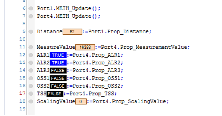
The MAIN Program will take the data from the IOLINK device and EL6224 for each Port.
| PROGRAM MAIN VAR Port4 :FB_IDWE_M12MM_NMS_A0; Port1 :FB_LR_TB2000; EL6751 :FB_EL6751_Basic; MeasureValue:INT; ScalingValue:BYTE; ALR1,ALR2,ALR3,OSS1,OSS2,TSS:BOOL; Distance:INT; END_VAR Port1.iPortOK:=EL6751.METH_Port_OK(1); Port4.iPortOK:=EL6751.METH_Port_OK(4); Port1.METH_Update(); Port4.METH_Update(); Distance:=Port1.Prop_Distance; MeasureValue:=Port4.Prop_MeasurementValue; ALR1:=Port4.Prop_ALR1; ALR2:=Port4.Prop_ALR2; ALR3:=Port4.Prop_ALR3; OSS1:=Port4.Prop_OSS1; OSS2:=Port4.Prop_OSS2; TSS:=Port4.Prop_TSS; ScalingValue:=Port4.Prop_ScalingValue; |
Result
Done!You got the IOLINK data for Port1 and Port4 from the EL6224 Terminal!
Download
Please download the Sample project from the link below.
https://github.com/soup01Threes/TwinCAT3/blob/main/Project_EL6224_Part1.tnzip