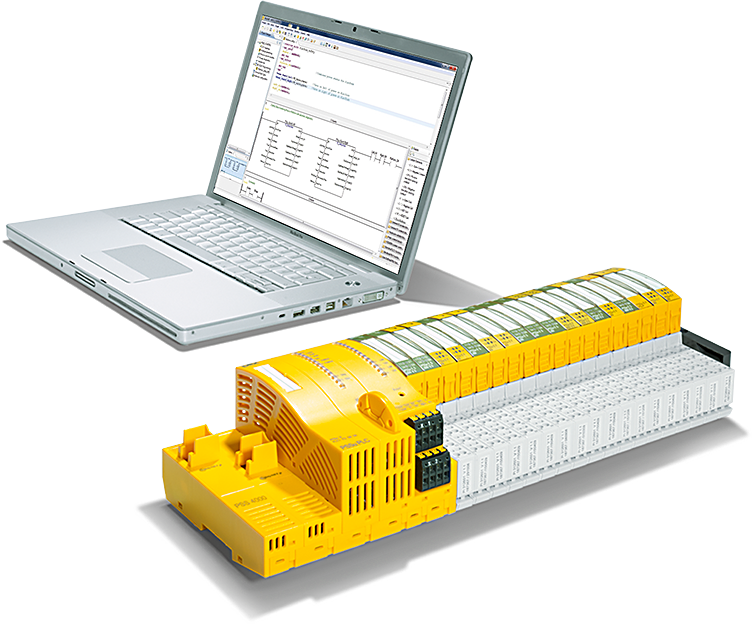
This is the fourth episode of the Pilz PSS4000 introduction. In the previous article, I explained the concept of creating a Safety program, variables, etc. This time, I would like to put together a more practical program. This time I will show you how to build a simple ESTOP safety application using the Function Block FS_EmergencyStop of the Pilz PSS4000.
Let’s start!
Thanks!
PSSu H PLC1 FS SN SD is borrowed from Pilz Japan, Thanks !!
PILZ
PILZ supports FA sites as a total solution supplier with safety and automation technology solutions, guaranteeing not only human safety, but also machine and environmental safety, to ensure the safe operation of machines and equipment. Pilz has 42 local companies and branches worldwide and is active in various fields such as packaging, the automotive industry, robotics applications, as well as wind power and railway technology.
Office:
ピルツジャパン株式会社
〒222-0033
横浜市港北区新横浜3-17-5
いちご新横浜ビル 4階
HP
Reterence Link
Function Block
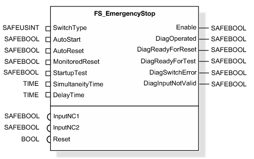
Firstly, Function Block – FS_EmergencyStop can implement 1:1 or 1:2 ESTOP operation applications for ETOP. It is important to note that to achieve the highest catalogs using FS_EmergencyStop, the ESTOP must be Dual Wiring, and the Test Pulse function must be enabled.
Parameters Type
Before introducing FS_EmergencyStop, let’s first discuss the Parameters of Pilz’s Function Block.
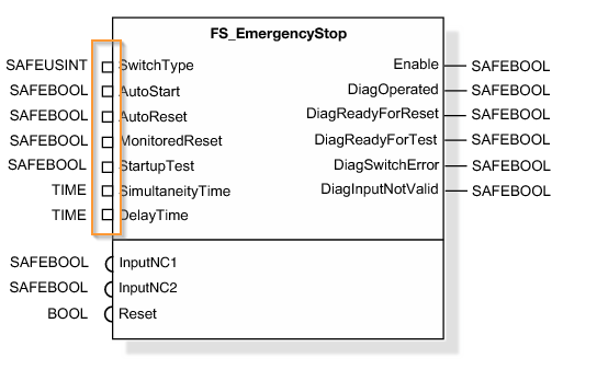
Parameters Points
The ICON square on the left side of Pilz’s Function Block is called “Parameter Points. In other words, they are input parameters.
I-Connection point
The right side of Pilz’s Function Block, the linear ICON, is called the I-Connection point. In other words, it is an output parameter.

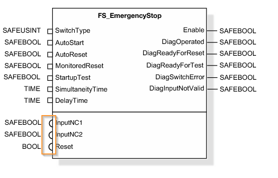
I-PI point/O-PI point
The semicircle ICON on the left side of the Function Block in Pilz is called I-PI point or O-PI point. This parameter is directly connected to IO Mapping.
VAR_INPUT
| Variable | Data Type | Description |
| SwitchType | SAFESINT | Switch Type 1 = 1 NC contact, 3 = 2 NC contactsThe SwitchType parameter should not be changed while the CPU is running. (DiagInputNotValid will be True) |
| InputNC1 | SAFEBOOL | Switch Input signal 1, True = NC contact Close |
| InputNC2 | SAFEBOOL | Switch Input signal 2, True = NC contact Close |
| AutoStart | SAFEBOOL | True=Automatic error activation, Default=False |
| AutoReset | SAFEBOOL | True=Automatic error activation, Default=False |
| MonitorReset | SAFEBOOL | Function Block reset signal detection settingFalse=Reset by Up Edge True=Reset by Down EdgeDefault=True |
| StartupTest | SAFEBOOL | Do not perform Function Test when False=StartupTrue=Function Test on StartupDefault=True |
| SimultaneityTime | Time | Detection time of InputNC1 and InputNC2 signals simultaneously True and False |
| DelayTime | Time | DelayTime for InputNC1 and InputNC2 |
| Reset | BOOL | error reset |
VAR_OUTPUT
| Variable | Data Type | Description |
| Enable | SAFEBOOL | True=No Error, ESTOP is not working |
| DiagOperated | SAFEBOOL | True=ESTOP not working |
| DiagReadyForReset | SAFEBOOL | True=ESTOP can be reset |
| DiagSwitchError | SAFEBOOL | True = Two NC contacts cannot be turned off and on simultaneously within a set time period. |
| DiagInputNotValid | SAFEBOOL | True=InputNC1/InputNC2 signals are disabled |
Application Example
SwitchType=1
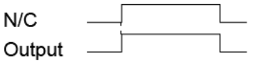
SwitchType=3,Switch on/off time=3s

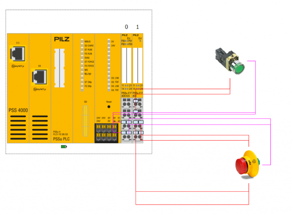
Wiring
Implementation
Programming
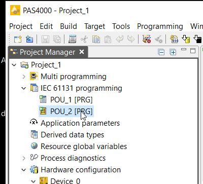
Now, continuing from the previous article, expand IEC 611313 programming>POU_2[PRG].
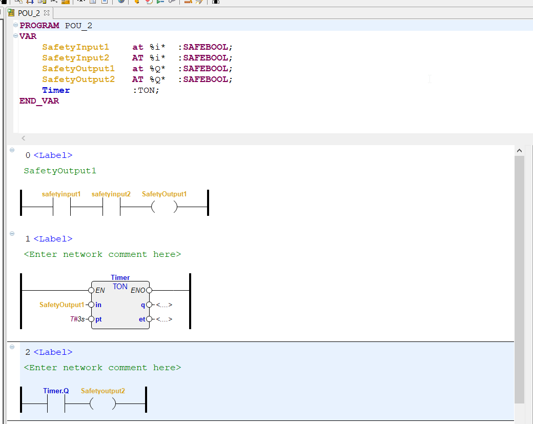
The Ladder Editor is now displayed.
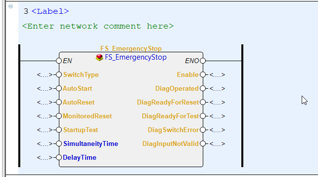
Search for “STOP” in the right palette and you will find the FS_EmergencyStop Function Block.

Select FS_EmergencyStop and add it to the new Network.

Here is the operation.

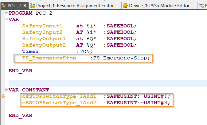
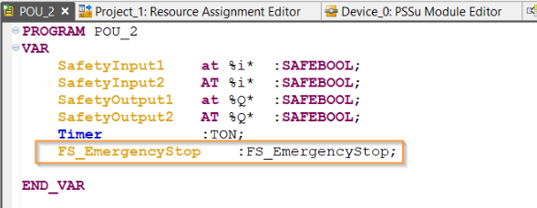
Define
Next, in the VAR area, define the Instance of FS_EmergencyStop and the SwitchType in the VAR CONSTANT.
Assign
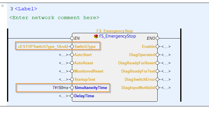
Assign the Instance defined previously to the FS_EmergencyStop Function Block.
Next, put in the necessary parameters – SwitchType and SimultaneityTime.
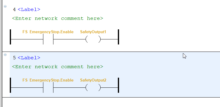
Output
Using the Enable output of the Function Block (i.e., ESTOP normal and the signal is also in True), Pilz PLC’s ESTOP turns on its own lamp and the lamp of the reset switch.
IO Mapping
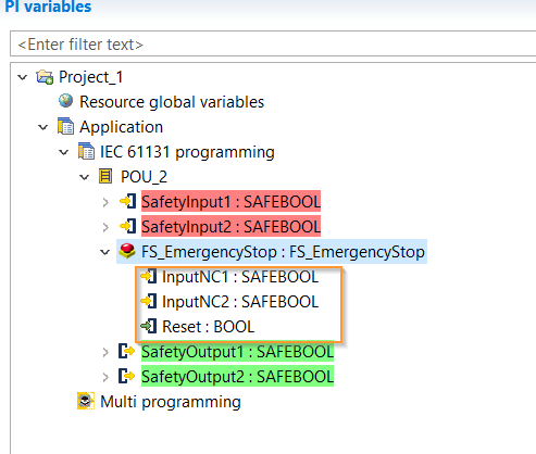
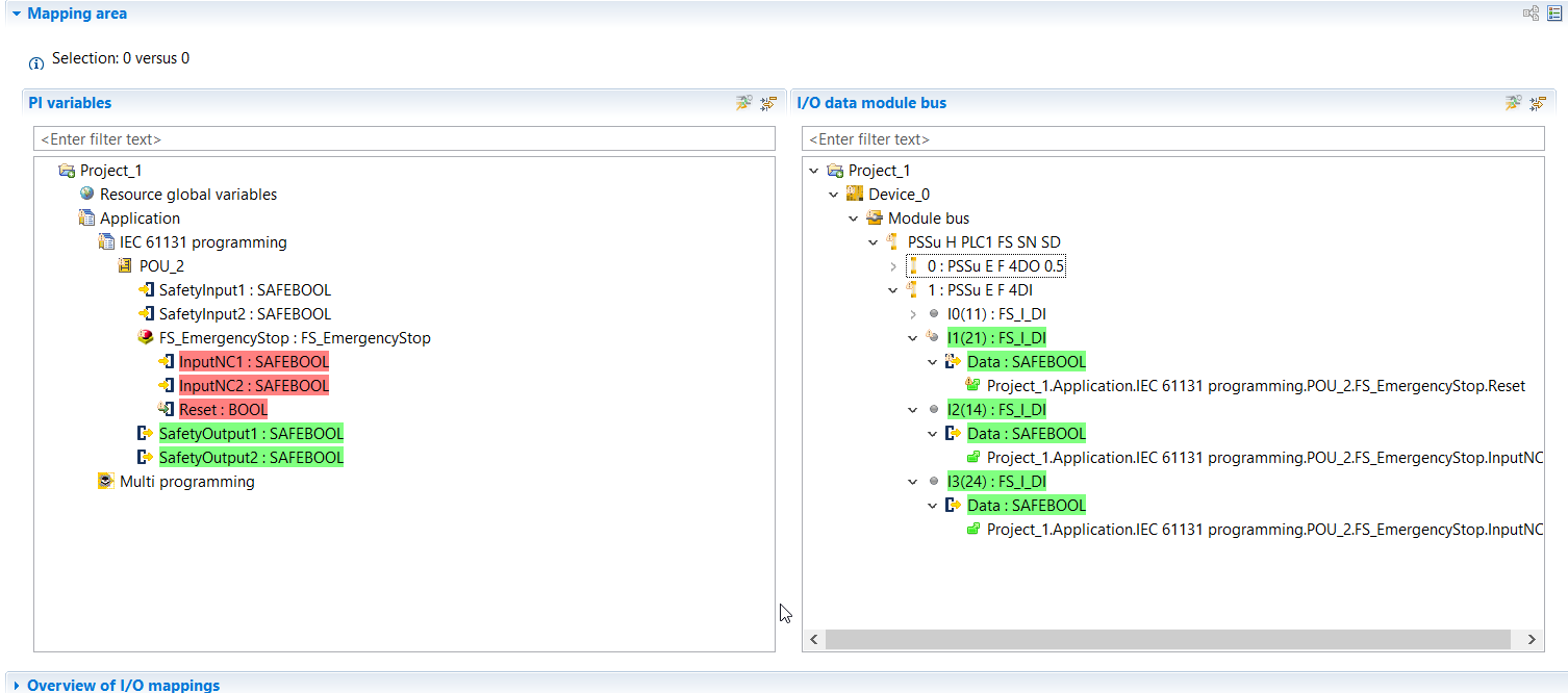
As I mentioned, there is no case to assign ESTOP signal parameters to FS_EmergencyStop, right? Remember I mentioned at the beginning that there are three types of parameters in the Pilz Function Block: InputNC1/InputNC2/Reset, and those three signals are I-PI Point signals that must be assigned directly from I/O Mapping.
Open I/O Mapping.

Do you see the Instance of FS_EmergencyStop in the Safety Program? That is the Instance defined in our VAR area.

When expanded, there are three signals InputNC1/InputNC2/Reset, which can be assigned directly to Safety IO.
The operations in this area were described in the previous article, so I will not describe them in detail.

Download
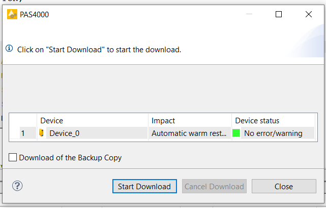
Finally, download the project by going to Target>Direct Project Download.
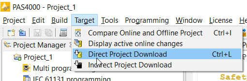
It starts with Start Download button.
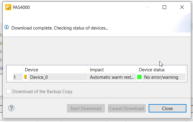
Confirm!

After a short wait, the download is completed.
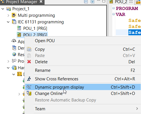
Result
Monitor the Program from the Dynamic program display to see the results.
And you can confirm the result from this youtube link: