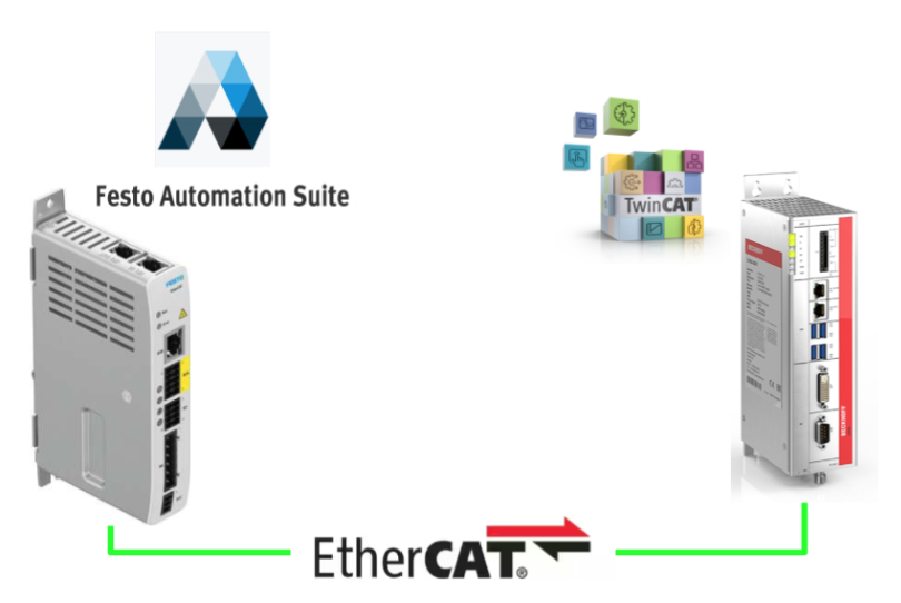
This is the second episode of the Servo Drive Tutorial for Festo’s CMMT-ST Series. This time, we will explain the points to keep in mind when linking the CMMT-AS Drive with the Beckhoff TwinCAT3 and the program.
Let’s get started!
Video
Here is a Japanese-language video I made, in which I test drive a CMMT-ST Servo Drive using the Festo Automation suite.
Festo.CMMT-ST Sero Drive Tutorial_Part1_Commissioning with Automation suite_EN
Here is a video I made explaining the program when using the Beckhoff TwinCAT3 and CMMT-ST Servo Drive.
Festo.CMMT-ST Sero Drive Tutorial_Part2_ How to control from Beckhoff Twincat3_EN
Reference Link
This is Servo Drive Tutorial Part 1 for Festo’s CMMT-ST Series, showing how to operate the Automation Suite and commission the CMMT-ST.
Festo also has CPX Series products and offers a comprehensive Fieldbus Solution for EIP/Profinet/Ethercat. Please refer to the following link if you like.
I have written my own Step by Step guideline connecting Festo CPX modules with Beckhoff TwinCAT, Keyence, and IQR.
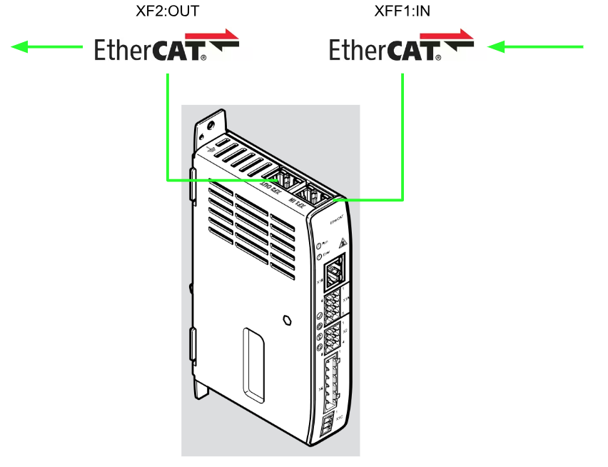
EtherCAT
IN
Port1 XF1 is the EtherCAT IN Port and Port XF2 is the EtherCAT Output Port.
Distributed clocks DC (Distributed Clocks)
All Real-Time-Clocks in all DC-capable EtherCAT slave controller ESCs of an EtherCAT network can be synchronized by means of a distributed ClockDC mechanism.
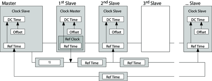
By default, the first DC-capable slave in the EtherCAT network controls the Clock Master with a reference clock (Ref Clock).
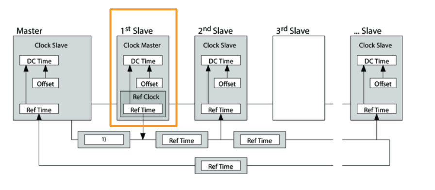
At intervals of a cycle, the master sends a synchronization datagram, in which the Clock Master writes the current reference time (Ref Time) to the reference clock.
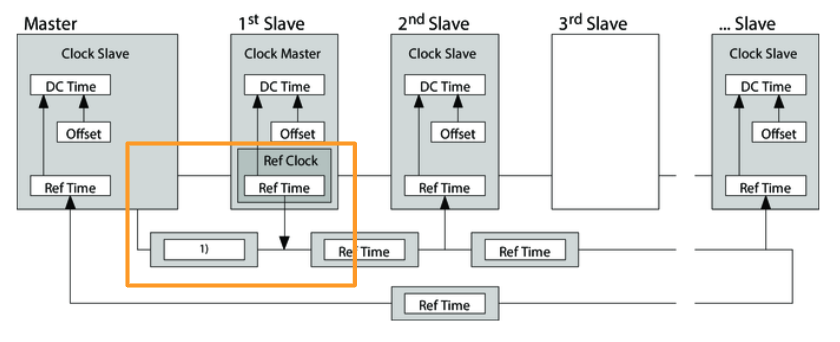
All subsequent Slaves read this value and the EtherCAT slave controller ASC calculates the time from the reference time (Ref Time) and the DC time from the execution time (Offset) calculated by the controller.
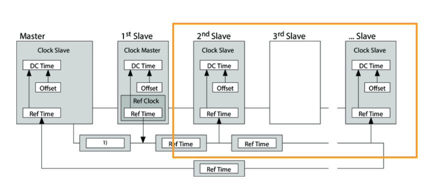
Its DC distributed clock is continuously synchronized with each subsequent synchronous datagram, and cyclical synchronous processing can be performed via the DC (e.g., multiple axes can be operated in a cyclical synchronous manner).
The transmission and processing of cyclical process data is controlled by the Sync Manager.
The transmission and processing of cyclical process data is specified in the synchronization, which is controlled by the DC (Distributed Clocks DC).
CMMT supports the following synchronization modes
- Free run (no synchronization)
- Process data (sync to SM2 event)
- Sync (sync with DC Sync 0 event)
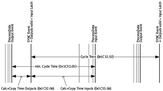
Process data communication
Process data communication involves the cyclic exchange of process data (e.g., settings and current values) between the CMMT and the Controller and others.
Each time a process data frame is executed, process data output is read from the frame and process data input is written to the frame.
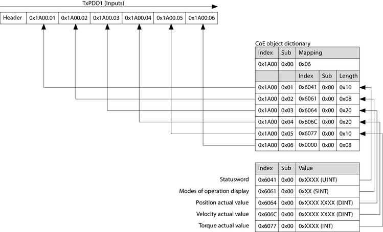
In the CMMT, the controller is Mapped to Sync Managers 2 and 3 for process data communication. The largest RxPDO/TxPDO then contains 16 output/input objects (Sub: 0x01 …) each with 64 bytes of user data. … .0x10) with 64 bytes of user data each can be allocated.
It is important to note that process data communication will start with the “Safe Operational” status; the CMMT will send TxPDOs to the controller from this status.” After reaching “Operational” status, the RxPDOs are processed and executed by the CMMT; CMMT synchronization is controlled by the DC (Distributed Clocks).

This is the Mapping for RxPDO01.

This is the Mapping for TxPDO01.
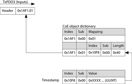
This is the Mapping for TxPDO03.
Download ESI File
Download the ESI File for CMMT-ST from Festo’s website.

Implementation
Festo Side
On the Festo side, Automation Suite is used to set limits, etc.
Monitor Limit
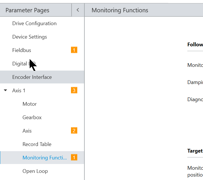
Open Axis>Monitoring Function.
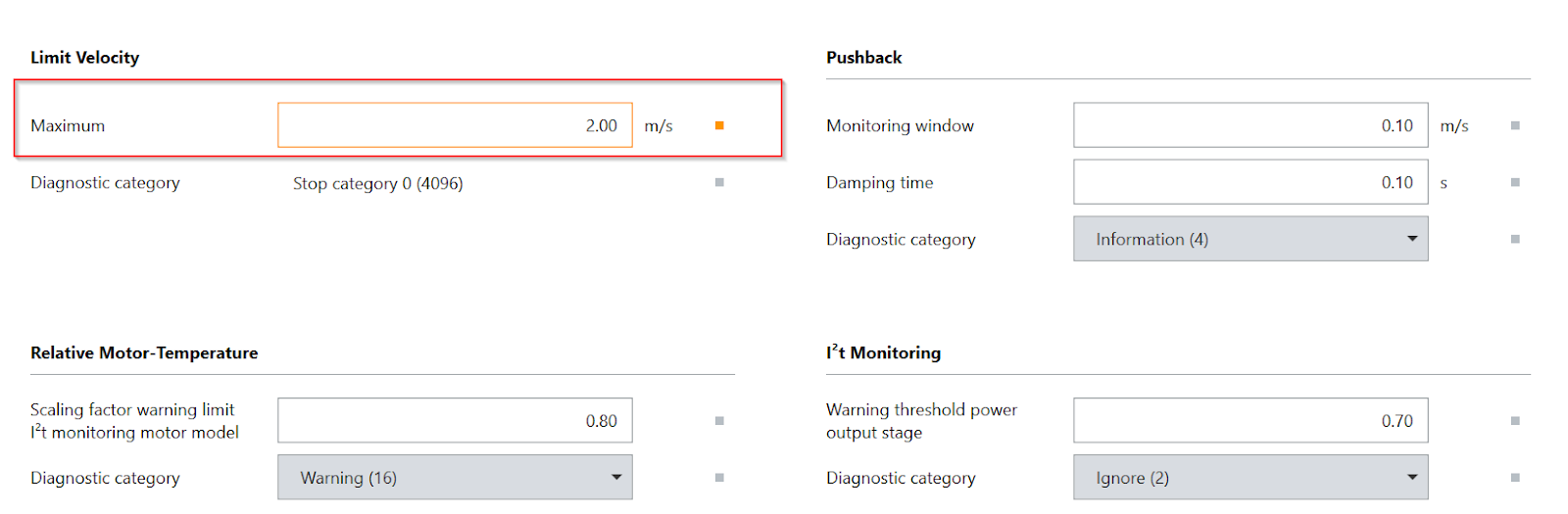
Limit Velocity allows you to change Servo’s Max Speed value.
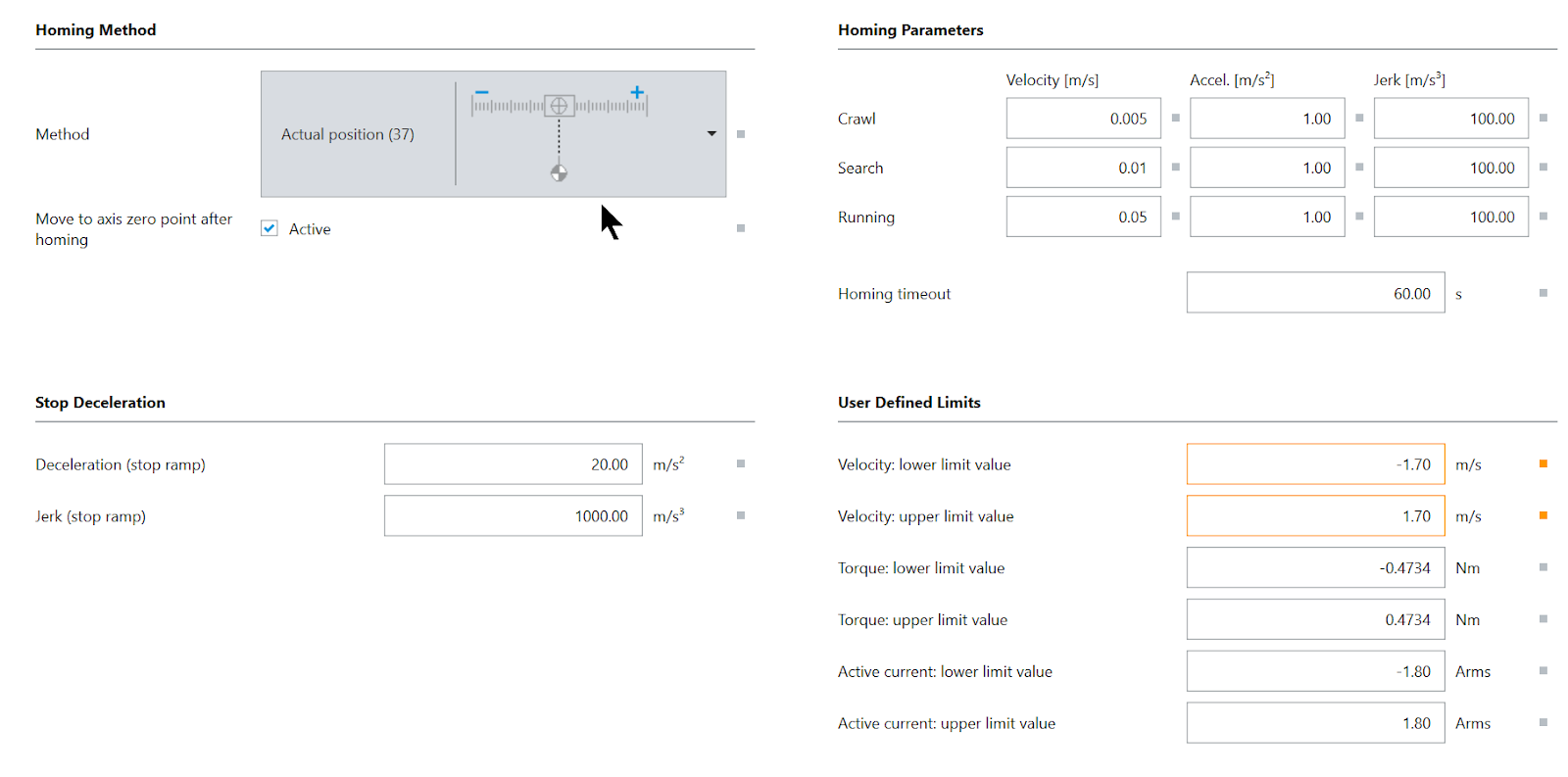
Axis Limit
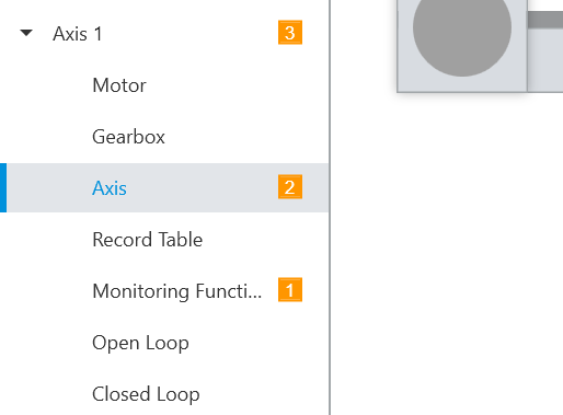
Open Axis1>Axis and make settings related to Drive position limits, etc.
The parameters such as Velocity Lower/Higher limit and homing method can be changed during the process.
Beckhoff Side
Install ESI File
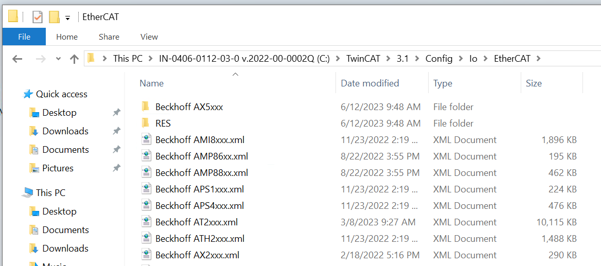
When the file downloaded from Festo HP is extracted, an XML file is stored.

Store this XML File in the following Path.
C:\TwinCAT\3.1\Config\Io\EtherCAT
Create New Project
Start TwinCAT and create a new project at File>New>Project.
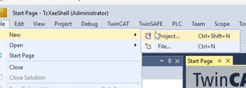
Select TwinCAT XAE Project >OK to proceed.

Done!A new TwinCAT project has been added.

Add EtherCAT Master
To add an EtherCAT Master to the TwinCAT Master, go to I/O>Device>Add New Item.
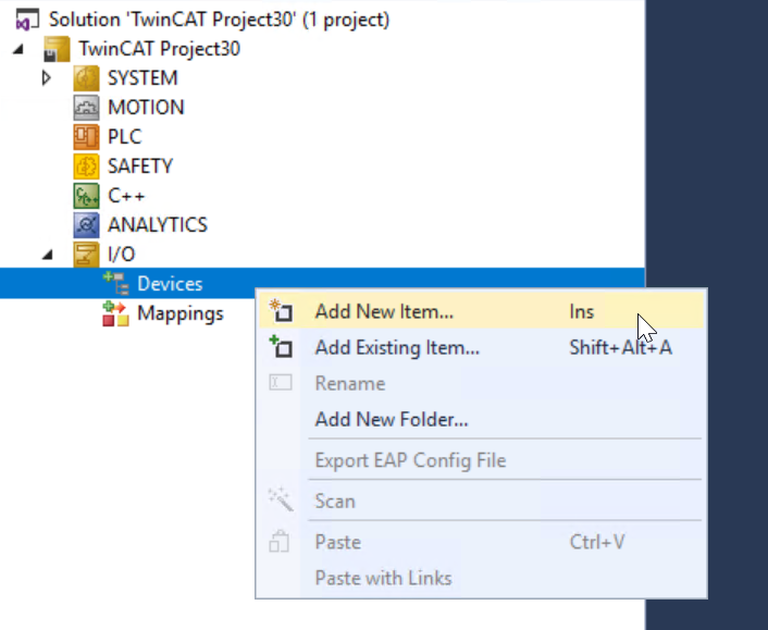
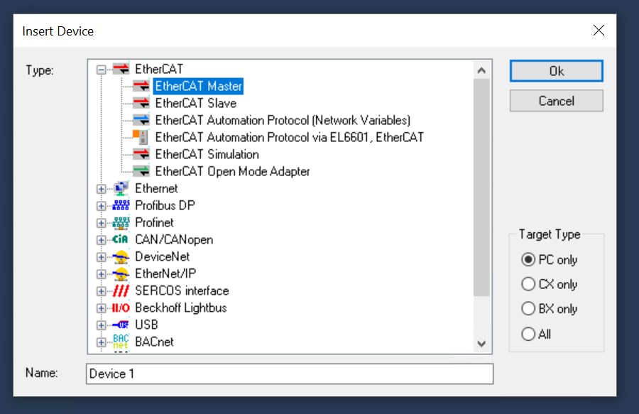
Select EtherCAT>EtherCAT Master>Ok.
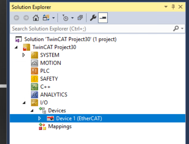
Done!EtherCAT Master has been added.
Adapter
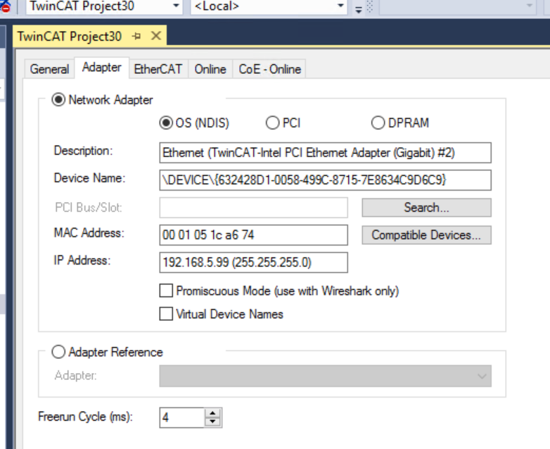
Double-click EtherCAT Master to open the Adapter tab.
From this tab, click the Search button to search for a Network Adapter that IPC can support.
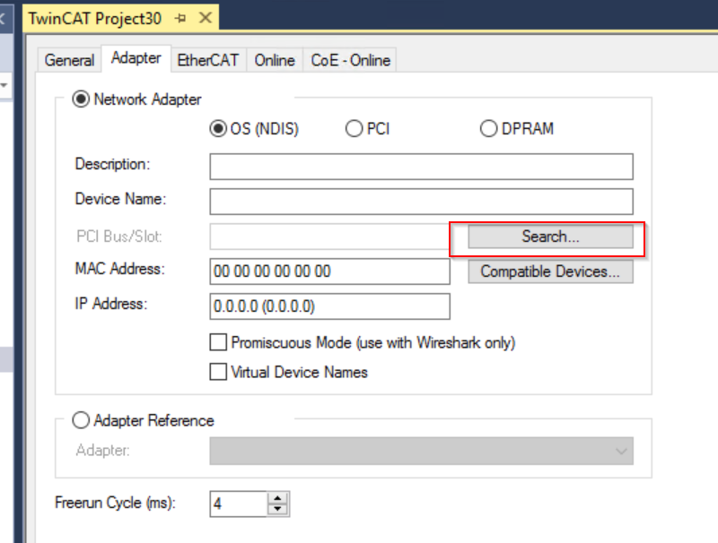
Set up the Network Adapter that you want to run as EtherCAT Master in it.
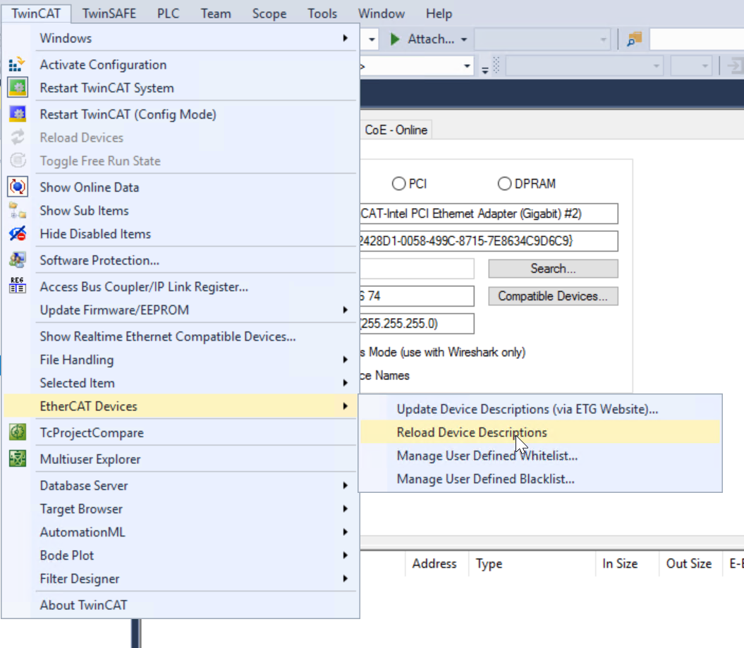
Update ESI File
Click on TwinCAT>EtherCAT Devices>Reload Device Descriptions to update the ESI File you have just imported into the TwinCAT System.
Add CMMT-ST
Add Festo CMMT-ST to the EtherCAT Network: right-click on EtherCAT Master>Add New Item.
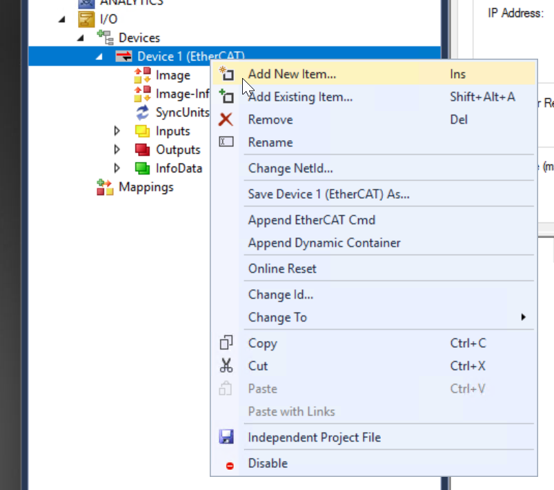
Choose Festo>CMMT>CMMT-ST and proceed with Ok.

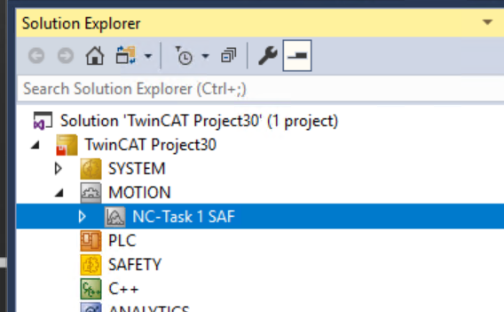
A popup will appear asking if you want to automatically add an NC Axis from TwinCAT? popup appears, select NC-Configuration and proceed with Ok.
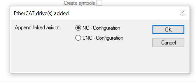
Done!CMMT-ST Drive and NC axes have also been added.
Configure DC
CMMT-ST’s has DC Synchronization Enabled by Default, but let’s check again just to be sure: click on CMMT-ST, open the DC Tab, and see if the Operation Mode is set to DC For Synchronization.

Clicking on “Advanced Settings” will take you to detailed settings for DC synchronization, but we will leave it at “Default” for now.

PLC
Add PLC Item
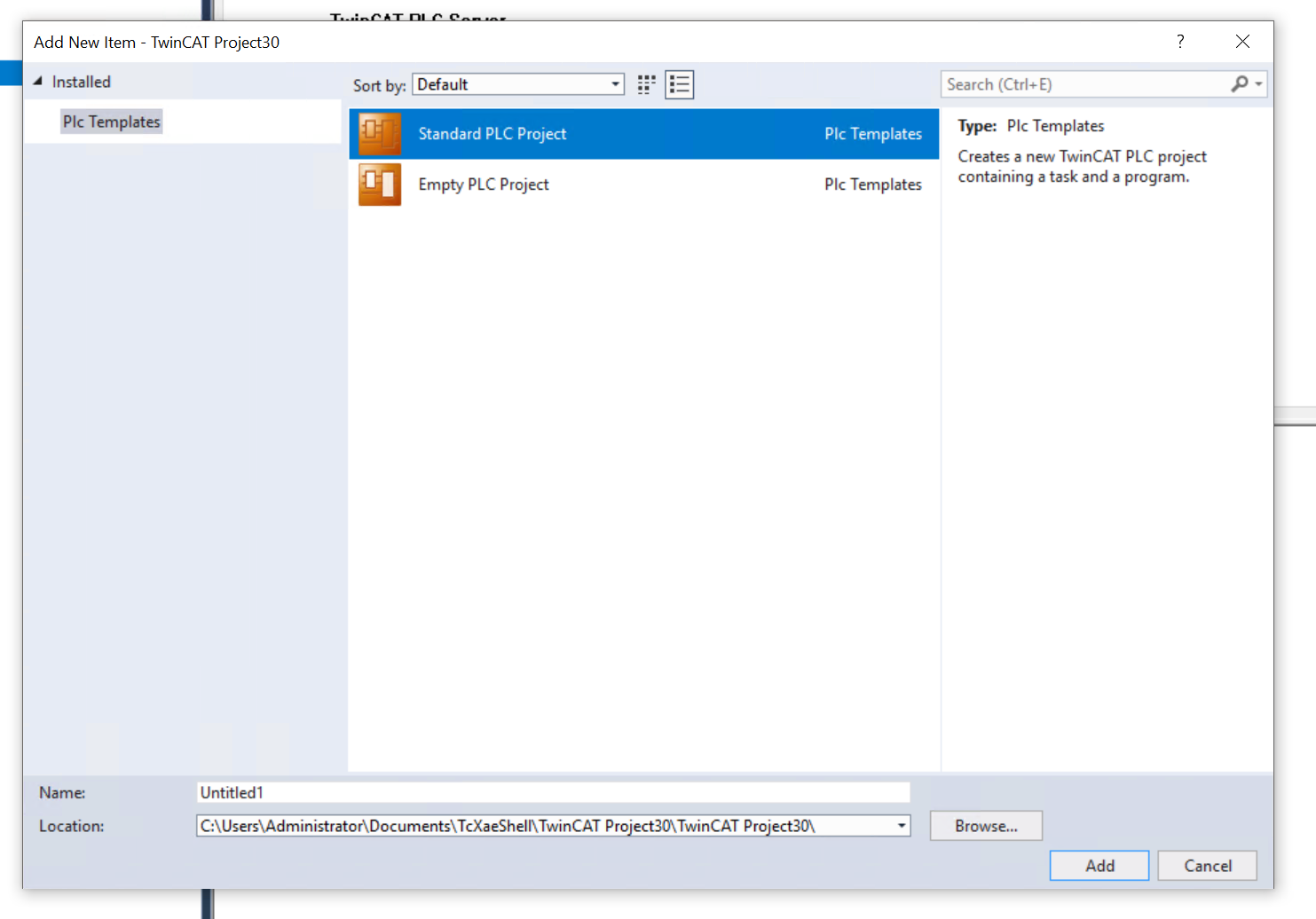
Next, to add a PLC to the project, go to PLC>Right Click>Add New Item.
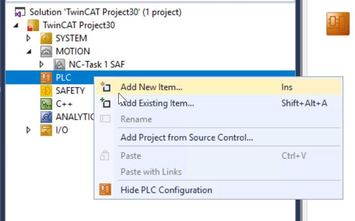
Select Standard PLC Project and proceed with Add.
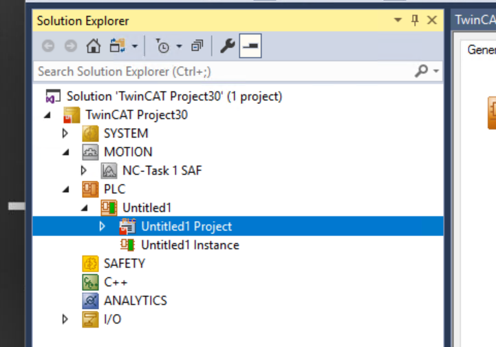
Done!PLCが追加されました。
Add GVL
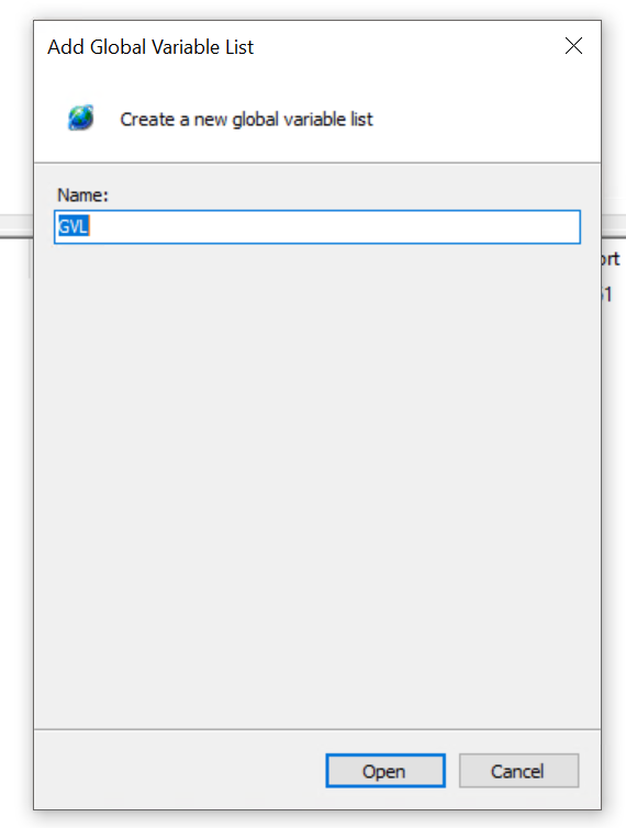
To add a Global Variables List, add Add>Global Variable List.

Enter the Global Variables List name and press Ok to proceed.
Define the following variables in the GVL
| {attribute ‘qualified_only’} VAR_GLOBAL iMsiMode AT %I*:SINT; qMsiMode AT %Q*:SINT:=8; FestoAxis :AXIS_REF; END_VAR |
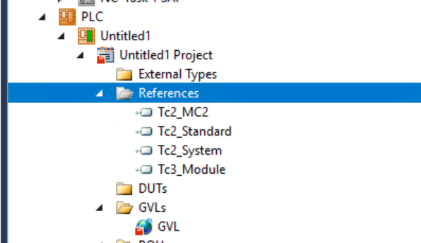
Add Library
To use AXIS_REF, you must add a library.
References>Add Library.

To use AXIS_REF, you must add a library.
References>Add Library.

Done!
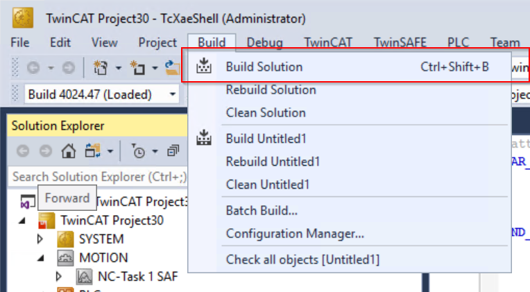
Build
Compile the project once with Build>Build Solution.
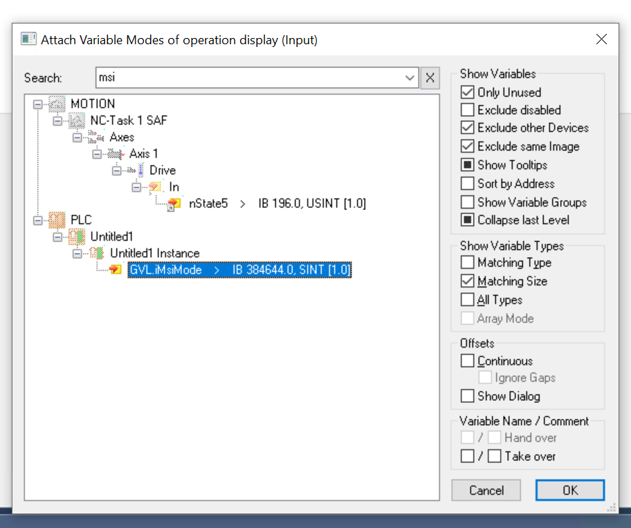
Change Mapping
Change the Mapping of the Drive on the Festo CMMT-ST.
Right click on CMMT-ST>Inputs>Modes of operation display>Change Link.

Let’s tie it to the GVL.iMsiMode defined earlier in GVL.
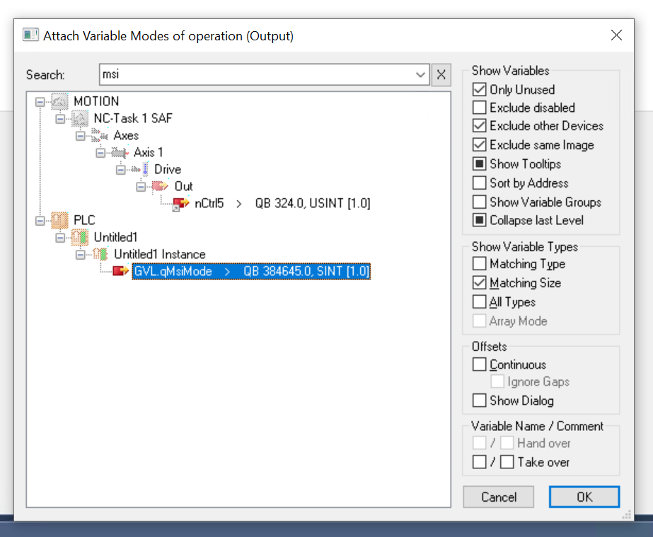
Outputs>Mode of operation is also right-click>Change Link.
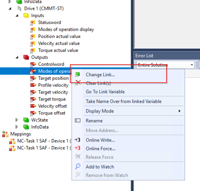
Let’s Link it to the GVL.qMsiMode defined earlier in GVL.
Program
The last one is Program, which reads the current state, speed, and position of Festo’s CMMT-ST, and also issues commands such as Servo ON, Jog Operation, etc.
| PROGRAM MAIN VAR //MC_Power mc_Power:MC_Power; MC_Power_Enable:BOOL; //MC_Jog mc_jog:MC_Jog; mc_Jog_Velocity:REAL; MC_Jog_Forward,MC_Jog_Backword:BOOL; //MC_Home mc_home:MC_Home; mc_home_execute:BOOL; //MC_Halt mc_halt:MC_Halt; mc_halt_exe:BOOL; //MC_MoveAbsolute MC_MoveAbsolute:MC_MoveAbsolute; MC_MoveAbsolute_Exe:BOOL; MC_MoveAbsolute_Position:LREAL; MC_MoveAbsolute_Velocity:LREAL; //MC_MoveRelative MC_MoveRelative:MC_MoveRelative; MC_MoveRelative_Exe:BOOL; MC_MoveRelative_Distance:LREAL; MC_MoveRelative_Velocity:LREAL; //MC_Reset mc_reset:MC_Reset; MC_Reset_Exe:BOOL; //MC_ReadActualPosition mc_ReadActualPosition:MC_ReadActualPosition; mc_ReadActualPosition_Enable:BOOL:=TRUE; MC_ActualPosition:LREAL; //MC_ReadActualVelocity MC_ReadActualVelocity:MC_ReadActualVelocity; MC_ReadActualVelocity_Enable:BOOL:=TRUE; MC_ActualVelocity :LREAL; //MC_ReadStatus MC_ReadStatus:MC_ReadStatus; MC_ReadStatus_Enable:BOOL:=TRUE; MC_Status :ST_AxisStatus; END_VAR //Read the ActualPosition of Axis mc_ReadActualPosition( Axis:=GVL.FestoAxis ,Enable:=mc_ReadActualPosition_Enable ,Position=>MC_ActualPosition ); IF mc_ReadActualPosition.Error THEN mc_ReadActualPosition_Enable:=FALSE; MC_ActualPosition:=0.0; END_IF //Read the ActualVelocity of Axis MC_ReadActualVelocity( Axis:=GVL.FestoAxis ,Enable:=MC_ReadActualVelocity_Enable ,ActualVelocity=>MC_ActualVelocity ); IF MC_ReadActualVelocity.Error THEN MC_ReadActualVelocity_Enable:=FALSE; MC_ActualVelocity:=0.0; END_IF //Read the Status of Axis MC_ReadStatus( Axis:=GVL.FestoAxis ,Enable:=mc_Power.Active ,Status=>MC_Status ); //MC_Power mc_Power.Enable_Positive:=TRUE; mc_Power.Enable_Negative:=TRUE; mc_Power( Axis:=GVL.FestoAxis ,Enable:=MC_Power_Enable ); IF mc_Power.Error THEN MC_Power_Enable:=FALSE; END_IF //MC_Reset mc_reset( Axis:=GVL.FestoAxis ,Execute:=MC_Reset_Exe ); IF mc_reset.Busy OR mc_reset.Busy THEN MC_Reset_Exe:=False; END_IF //MC_Halt mc_halt( Axis:=GVL.FestoAxis ,Execute:=mc_halt_exe ); IF mc_halt.Busy OR mc_halt.Error THEN mc_halt_exe:=FALSE; END_IF //MC_Jog mc_jog.Mode:=E_JogMode.MC_JOGMODE_CONTINOUS; mc_jog( Axis:=GVL.FestoAxis ,JogBackwards:=MC_Jog_Backword AND MC_Status.Operational AND NOT MC_Jog_Forward ,JogForward:=MC_Jog_Forward AND MC_Status.Operational AND NOT MC_Jog_Backword ,Velocity:=mc_Jog_Velocity ); //MC_Home mc_home.HomingMode:=MC_HomingMode.MC_Direct; mc_home( Axis:=GVL.FestoAxis ,Execute:=mc_home_execute ); IF mc_home.Busy OR mc_home.Error THEN mc_home_execute:=FALSE; END_IF //MC_MoveAbsolute MC_MoveAbsolute( Axis:=GVL.FestoAxis ,Execute:=MC_MoveAbsolute_Exe AND MC_Status.Operational AND MC_Status.Homed AND NOT MC_Status.HasJob ,Position:=MC_MoveAbsolute_Position ,Velocity:=MC_MoveAbsolute_Velocity ); IF MC_MoveAbsolute.Busy OR MC_MoveAbsolute.Error THEN MC_MoveAbsolute_Exe:=FALSE; END_IF // MC_MoveRelative( Axis:=GVL.FestoAxis ,Execute:=MC_MoveRelative_Exe AND MC_Status.Operational AND MC_Status.Homed AND NOT MC_Status.HasJob ,Distance:=MC_MoveRelative_Distance ,Velocity:=MC_MoveRelative_Velocity ); IF MC_MoveRelative.Busy OR MC_MoveRelative.Error THEN MC_MoveRelative_Exe:=FALSE; END_IF |
Confiugure Parameters
The last step is to change the parameters of the NC axes. Here some parameters must be matched with those set in Festo Automation Suite.
Enc
The first thing that must be matched with Festo’s Drive is the Enc setting.
Parameters has a parameter called Scaling Factor Numbertor.

Go to Festo Automation Sutie>Field bus and set it according to the setting of the Position item.In the figure below, the value is -6, so it is 0.000001.
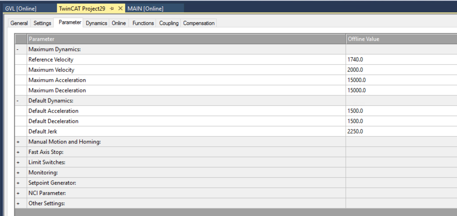
Axis Setting
The next step is to configure the Axis itself.
Reference Velocity, etc., should also match the actual motor data.
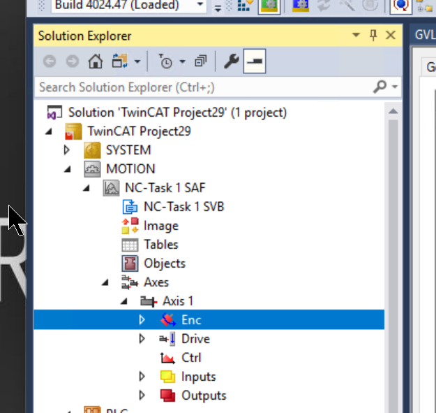
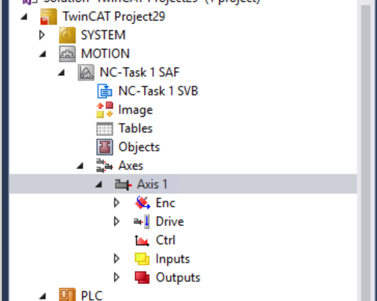
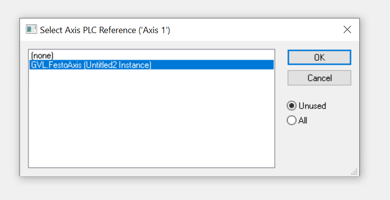
Link to PLC
Open Axes>Axis1 to connect Axis to AXIS_REF in TwinCAT.
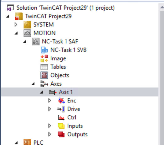
Click the Link to PLC button on the Parameters Tab.

Tie it to the AXIS_REF defined in GVL.
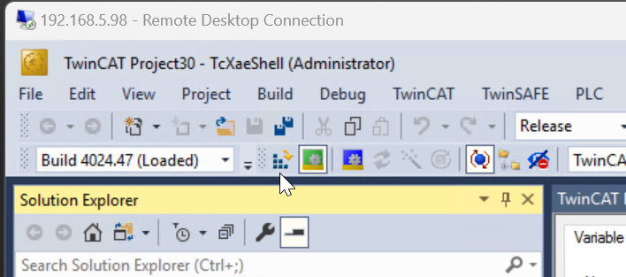
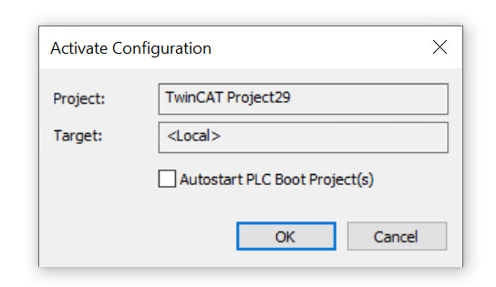
Activate
Download Hardware Configuration to Runtime.
Proceed with Ok.
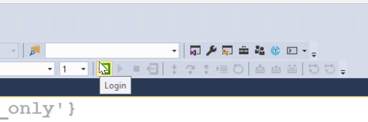
Login
Finally, download the program to Runtime.
Result
MC_Power to turn on the Drive
This video shows the operation to Power On Festo’s Servo Drive from TwinCAT3.
MC_Reset to reset the Drive
This video shows the operation to reset Festo’s Servo Drive from TwinCAT3.
MC_MoveRelative
This video shows the relative positioning of Festo’s Servo Drive from TwinCAT3.
MC_MoveAbsolute
This video shows the absolute positioning operation of Festo’s Servo Drive from TwinCAT3.
MC_Jog
This video shows the JOG operation of Festo’s Servo Drive from TwinCAT3.
Download
Download the project from this link.
https://github.com/soup01Threes/TwinCAT3/blob/main/TwinCAT_SampleProject_WithFestoSMMT%20Servo.tnzip