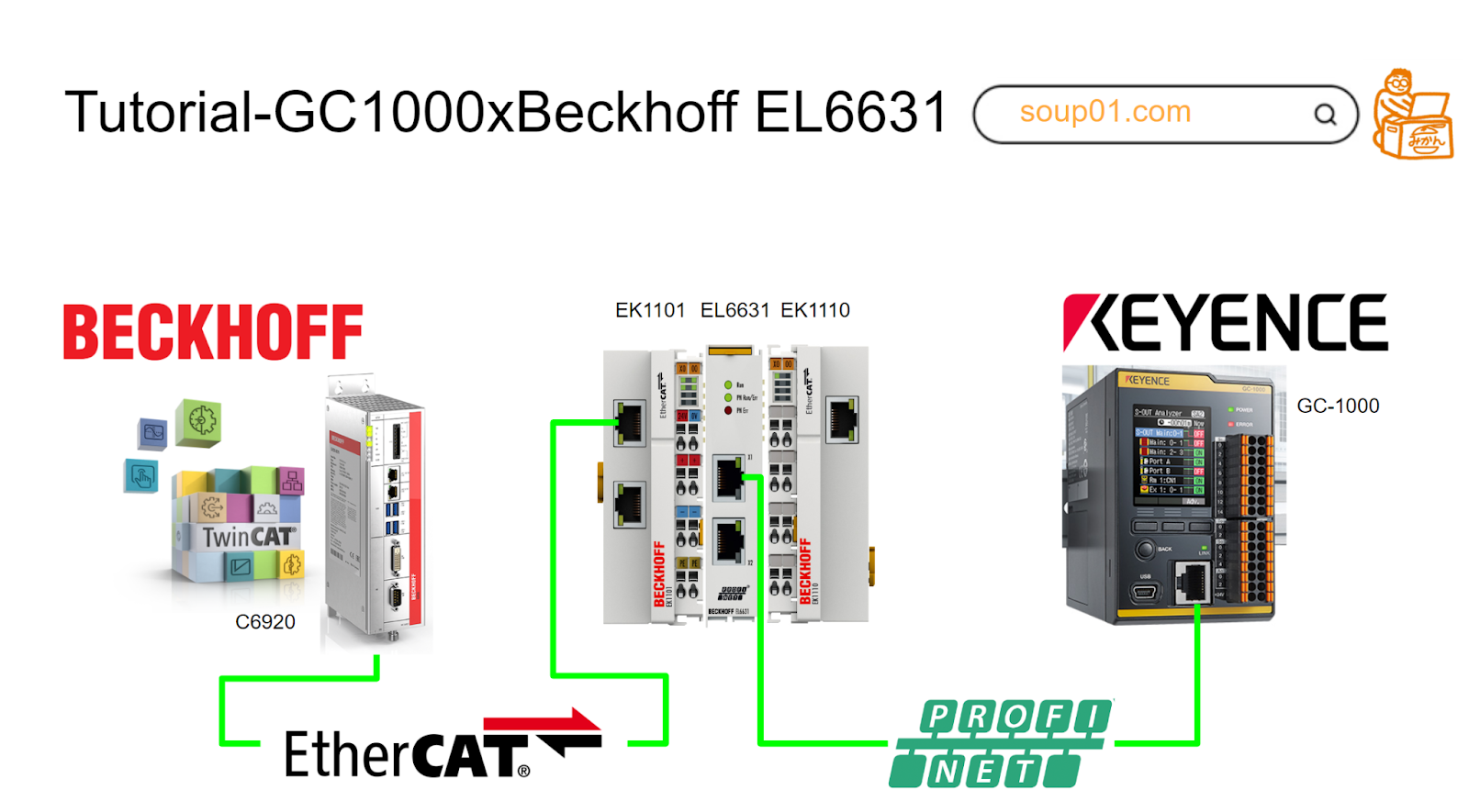
The GC1000 can support EtherNet/IP™, PROFINET, UDP, Modbus/TCP, or MC protocol communication. The subject of this article is the Profinet communication between the Beckhoff EL6631 Profinet Terminal and the GC1000.
Let’s get started!
Reference Link
Reference Video
Beckhoff. Profinet connection with EL6631 and Keyence GC1000 Tutorial
GC1000 And Profinet
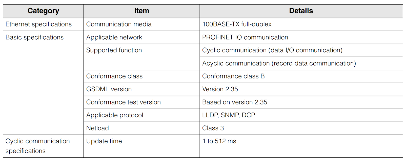
This is the Profinet version of GC1000.
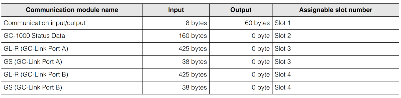
This is the GC1000 Mapping. Please refer to the GC1000 Manual for detailed information.
EL6631
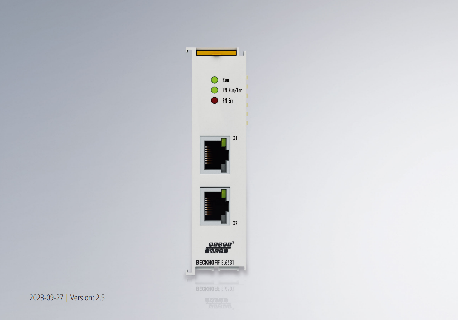
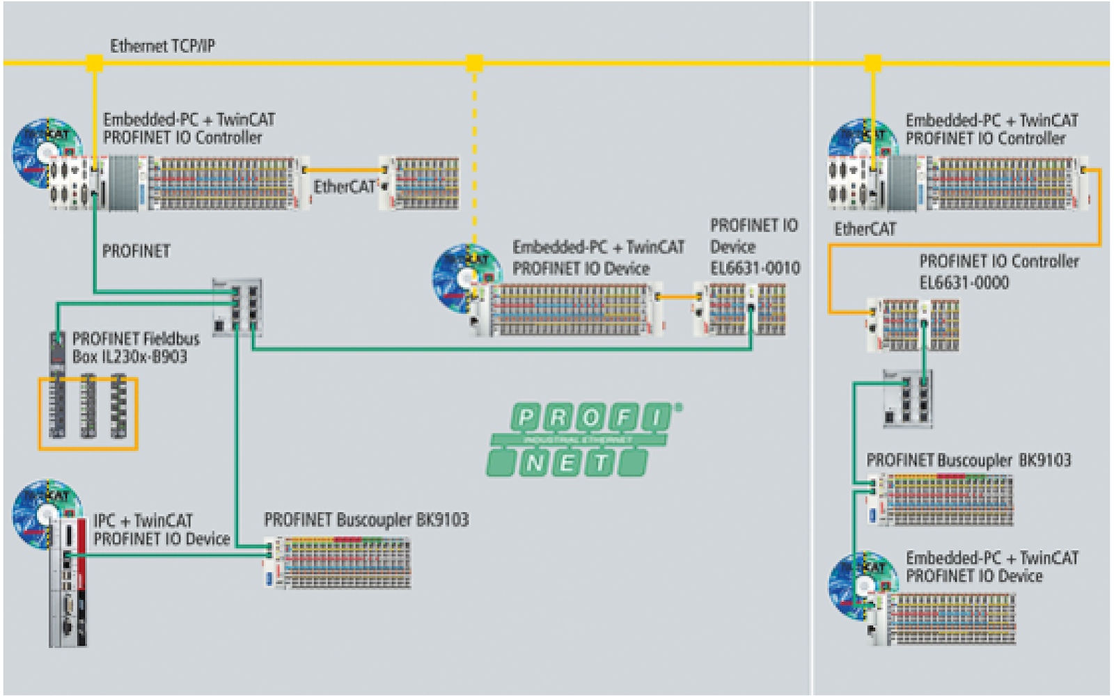
The PROFINET IO Controller Terminal EL6631 supports complete real-time (RT) and diagnostic functions and all services according to Conformance Class B. Up to 15 PROFINET IO devices can be connected to the EL6631.
PROFINET IO Controller can turn a Beckhoff PC-based control system into a PROFINET IO controller (standard Ethernet interface).
By connecting with the EL663x PROFINET Terminals for EtherCAT I/O systems, EtherCAT can be easily coupled. The EtherCAT network can also exchange data with PROFINET IO devices, as shown in the figure below.
There are two types of PROFINET: PROFINET I/O and PROFINET CBA, but TwinCAT supports PROFINET I/O.
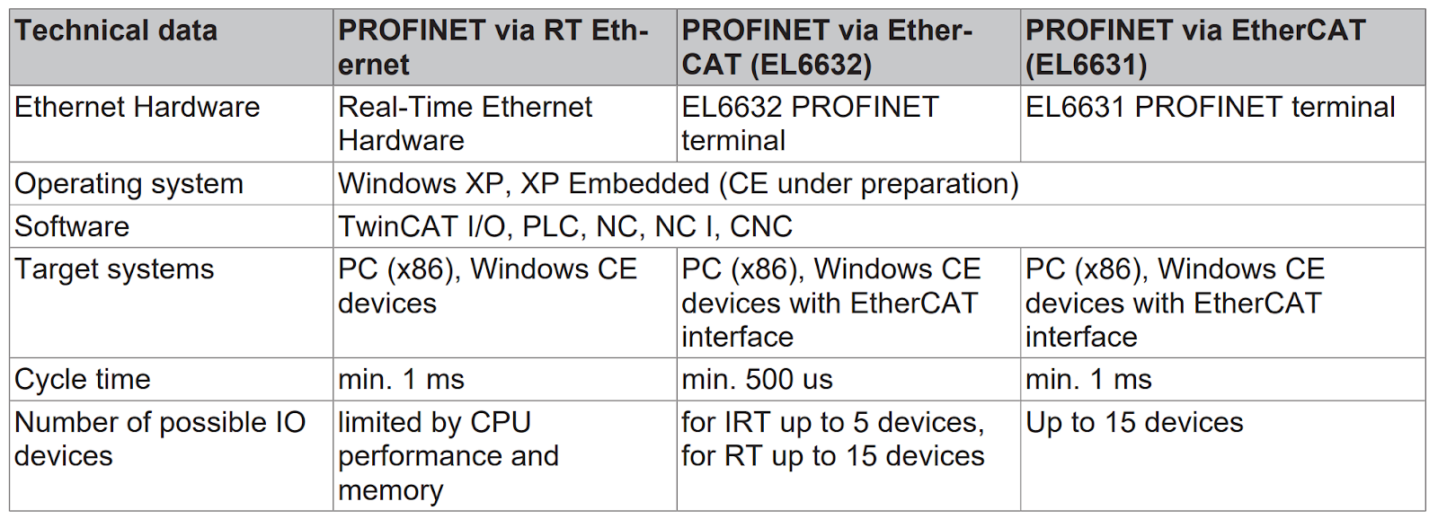
Currently, the TwinCAT PROFINET I/O controller can configure with:
- The EL6631 supports RTClass1 and can handle all Cycle times defined in RTClass1. (Cycle times can be specified in steps from 1 ms to a power of 2 (1, 2, 4, 8, …. .ms).
- The EL6632 can communicate with RTClass1 and RTClass3, and the minimum cycle time currently supported by the EL6632 is 500 μs (for RTClass3).
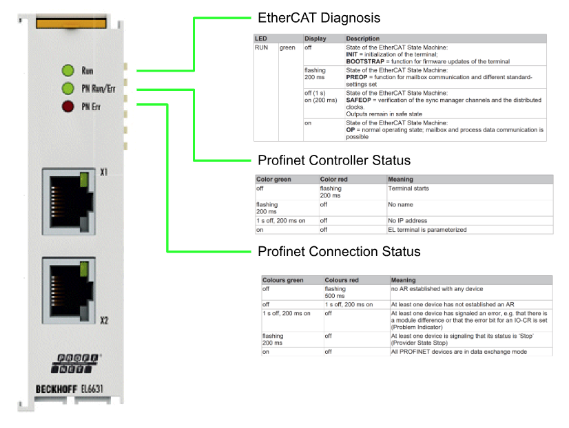
LED
This is the LED status of EL6631.
Implementation
Keyence Side
Ethernet Setting
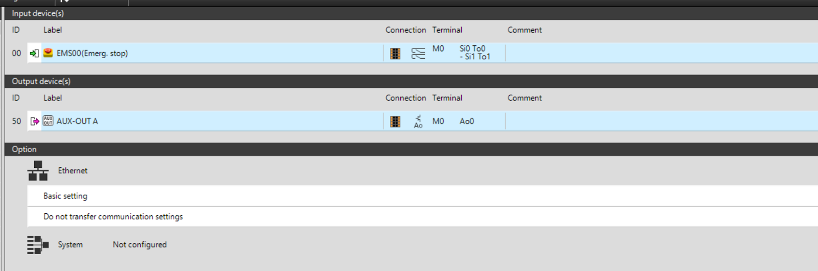
Open Option>Ethernet>Basic Setting.
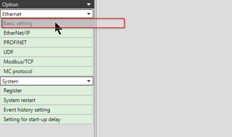
The Options section displays the Ethernet Basic Setting items.
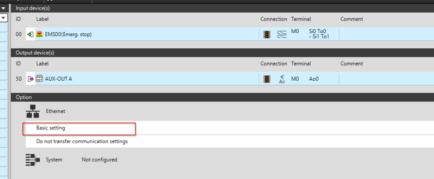
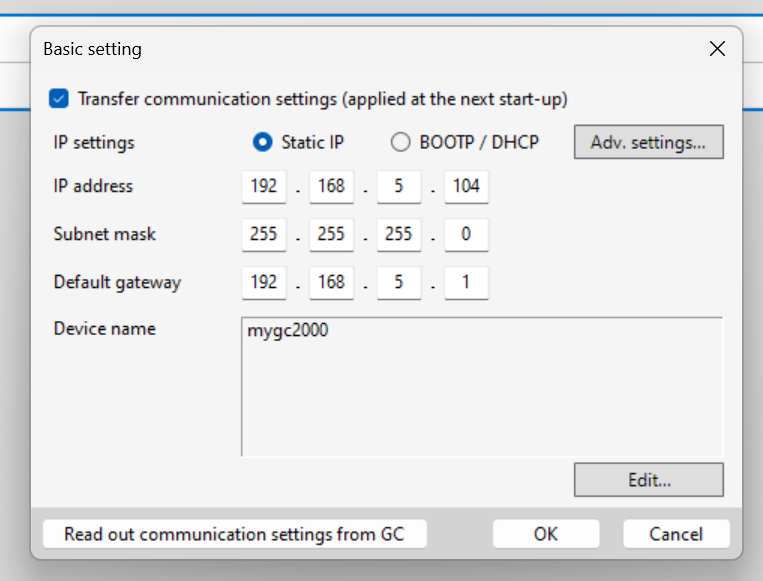
Basic Setting
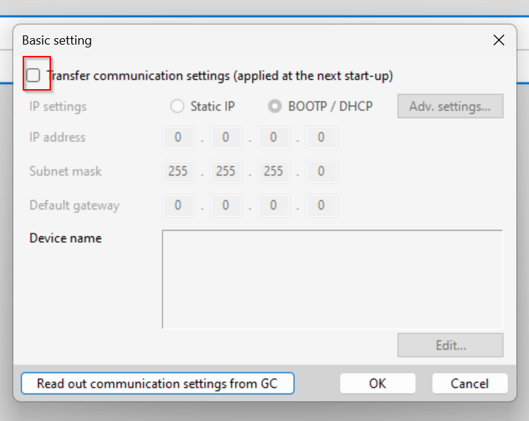
Click “Basic Setting” to set the IP address and other settings.
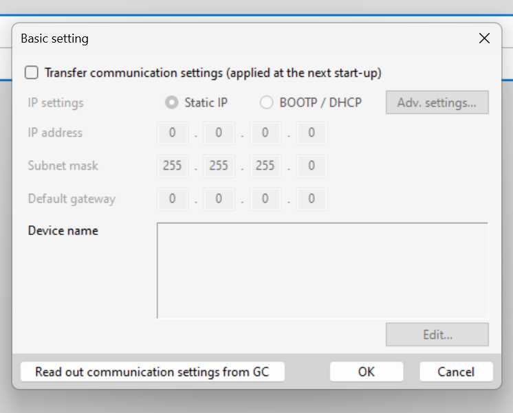
The Basic Setting screen appears.
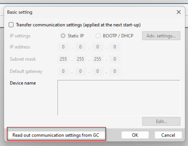
Read out Setting
If you want to get the current settings, click on Read out communication settings from GC.
Transfer Setting
Checkbox under Transfer Communication settings to transfer the current network settings to the CPU.
IP Setting
You can choose how to configure IP, such as Static IP or DHCP.

This time, select Static IP and set the IP address according to the application.
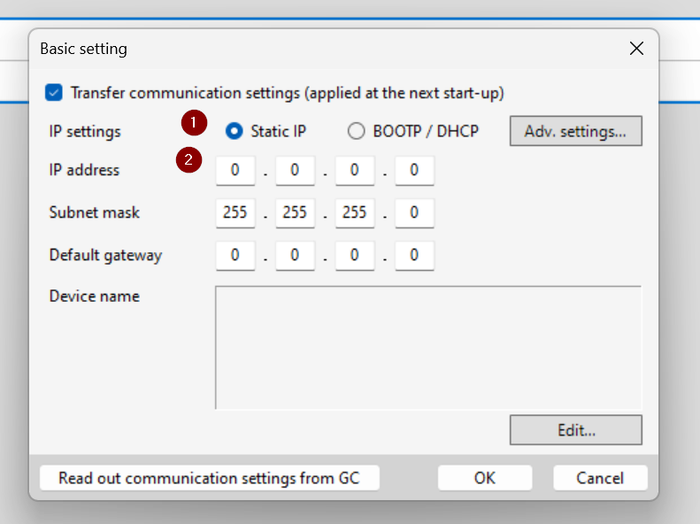
This is OK.
Device Name
When Profinet is used, the CPU device name can be set from the Edit button.
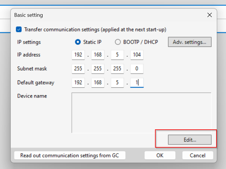
The Edit device name screen appears.
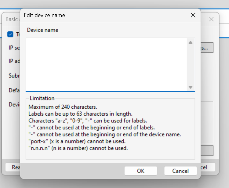
Please configure according to your application. But later, TwinCAT will use the DCP Protocol to assign the IP address.

Done!Proceed with Ok.
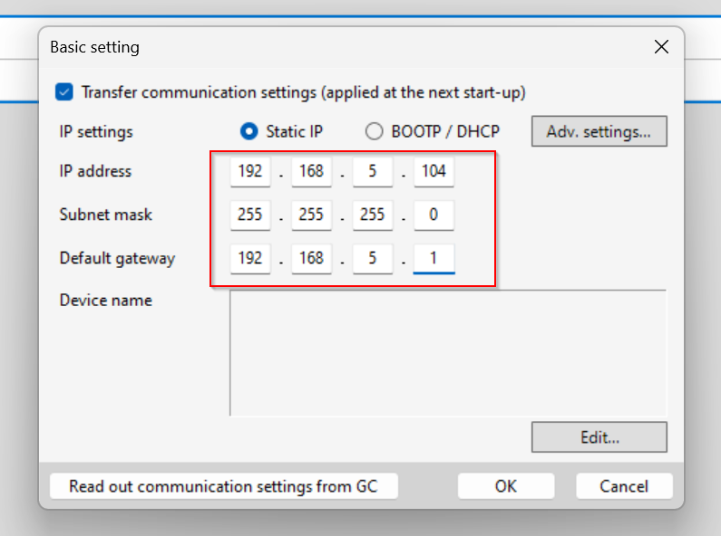
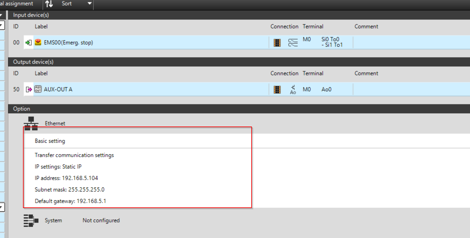
Result
As shown in the figure below, the Basic Setting has been reflected.
PROFINET Setting
Next, click on Ethernet>PROFINET to change the PROFINET Setting.
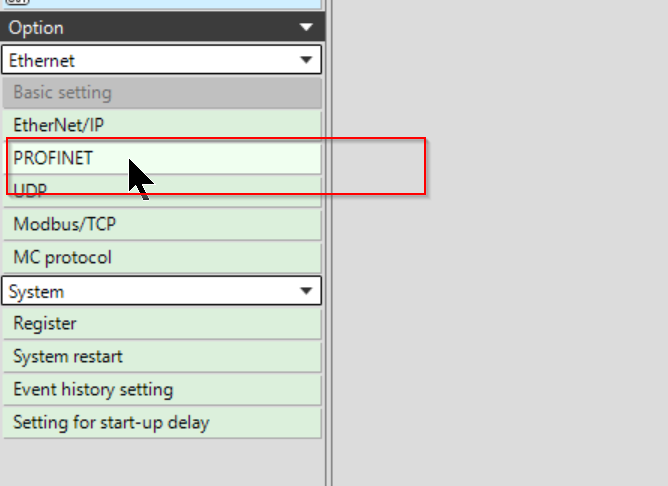
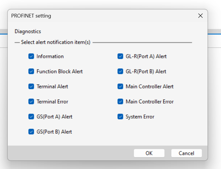
The PROFINET configuration screen is now displayed.
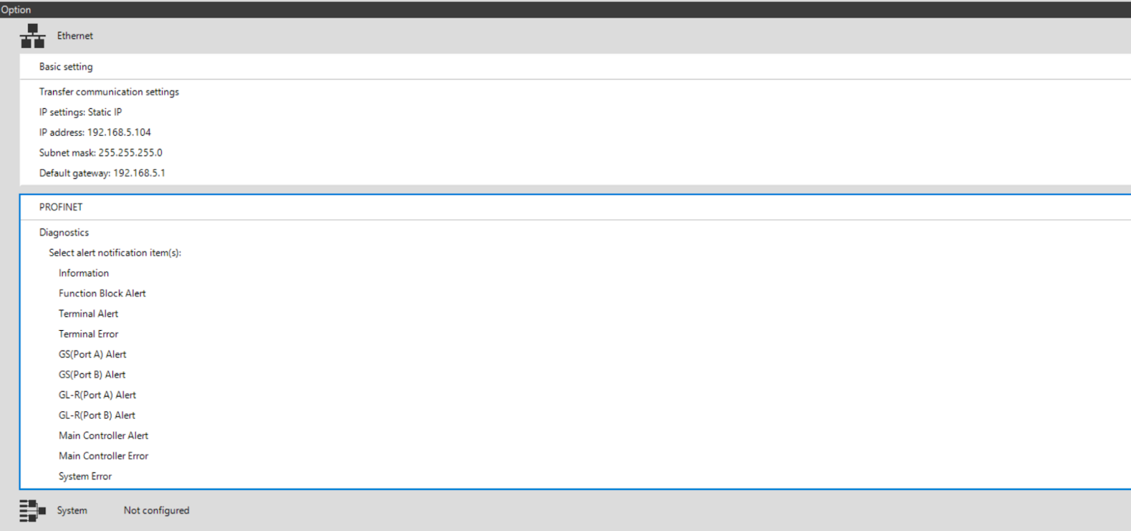
Check in the necessary diagnostic information for your application.
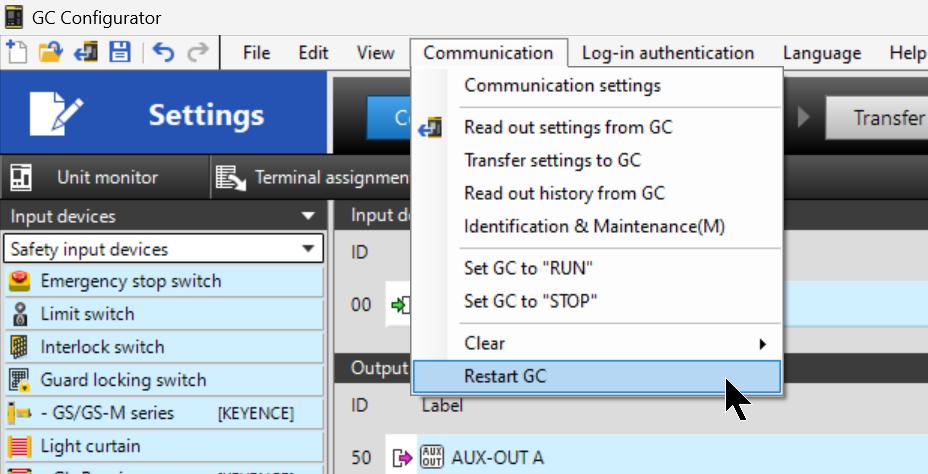
Restart GC
Transfer the project settings to the CPU and restart the CPU with Communication>Restart GC. The GC-1000 side is now ready.
Configuration
The next step is to define the Reset switch and Profinet inputs and outputs on the GC1000.
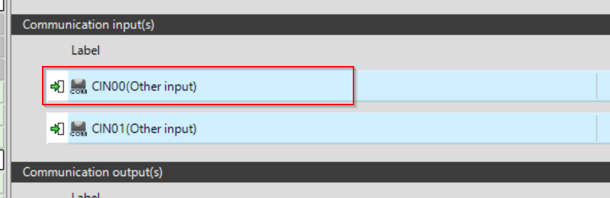
Inputs
Other input devices > Drop the reset switch on the input device.
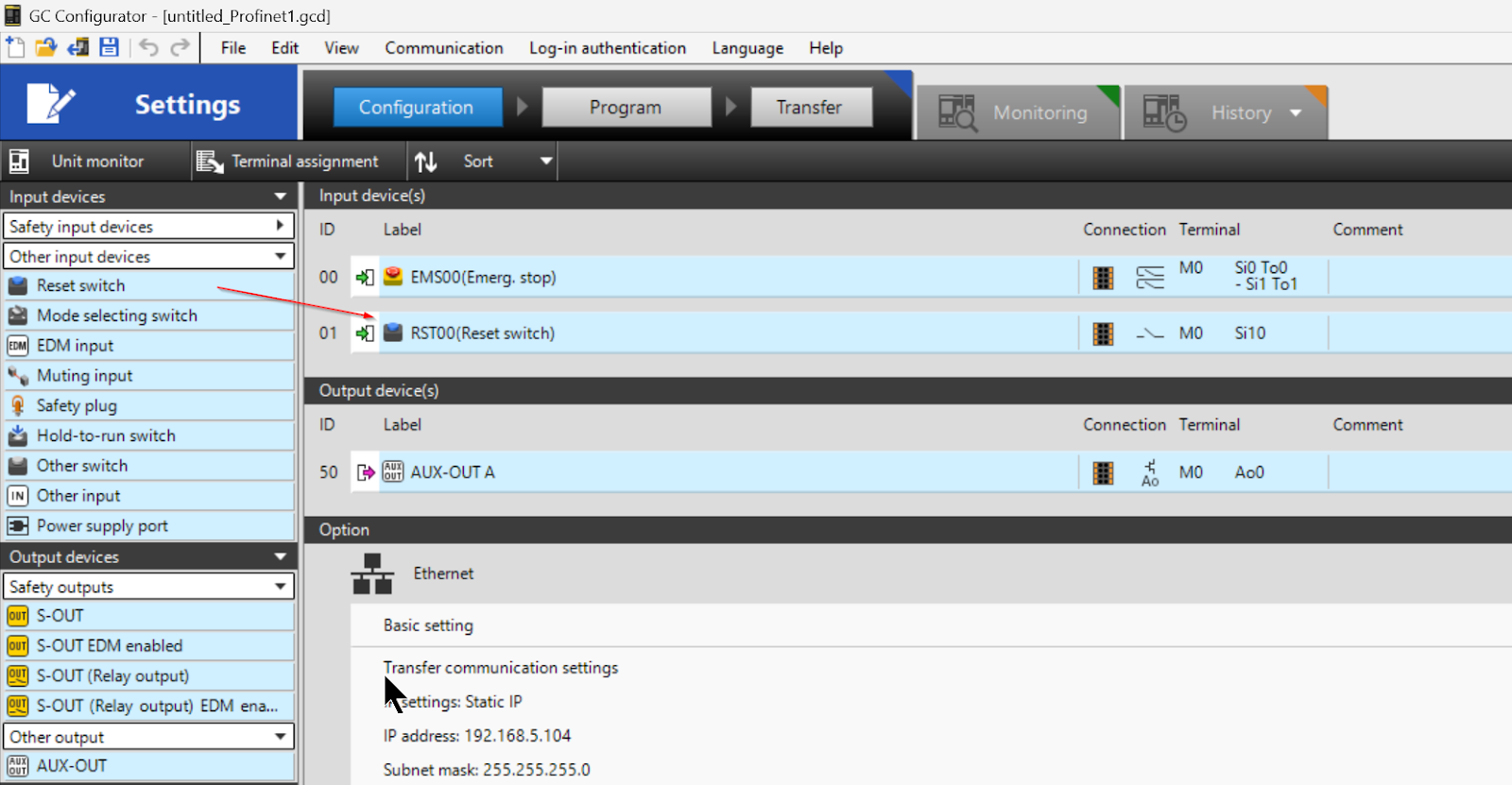
Done!
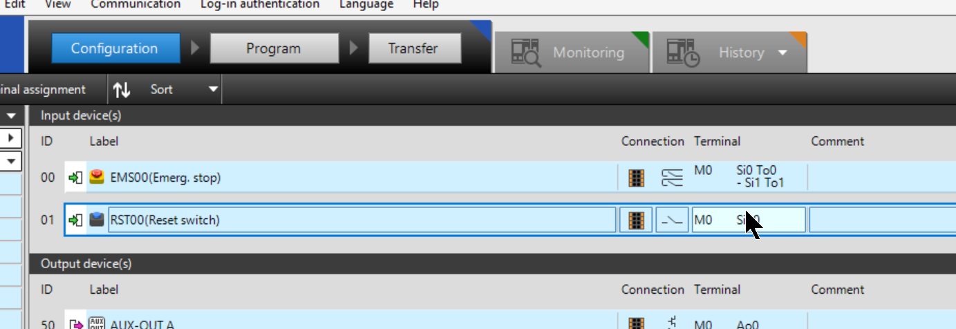
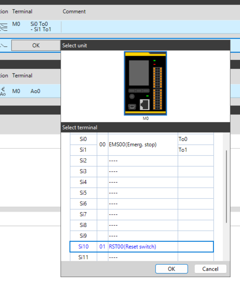
Click on the Terminal button and set the reset button to match the terminal block to which it is connected. In this case, it will be Si10.
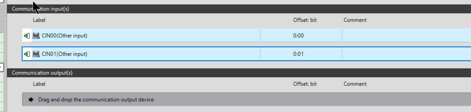
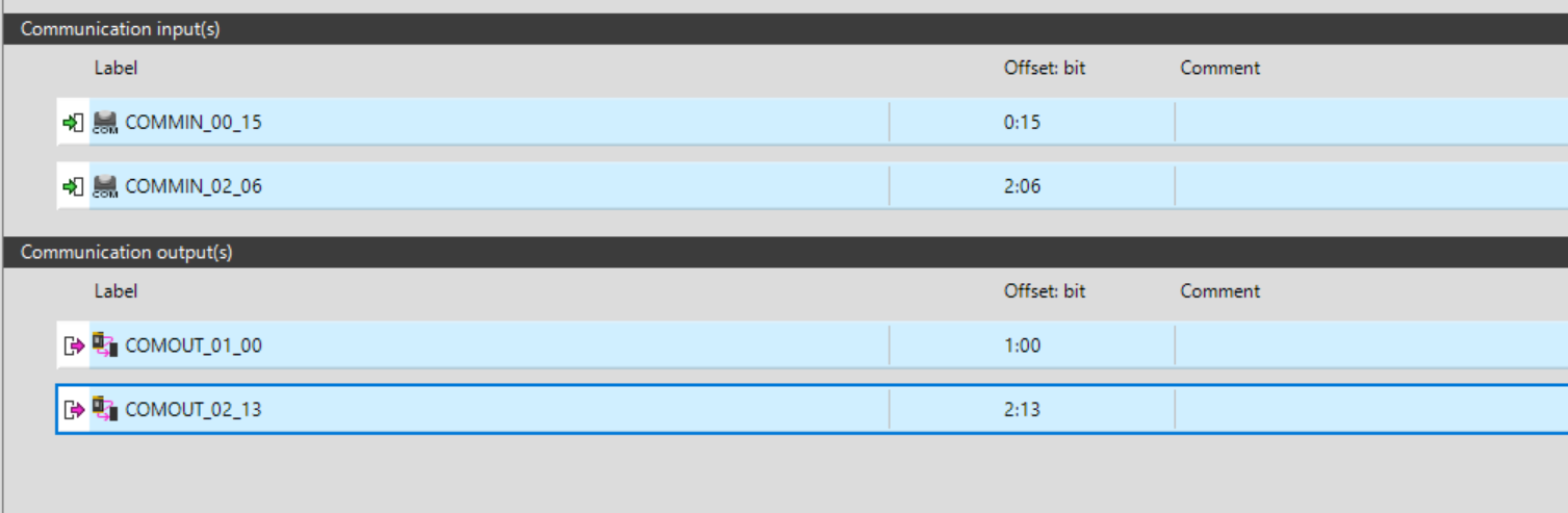
Communication inputs
Next, let’s drop Comm.Input into Communication input(s). 32 pieces of 8-bit communication input data are already defined in Keyence’s Profinet Device GSDML File definition. We can drop them in Other comm. input(s) and use them in the Safety program.
Any Bit data not defined in the Communication input(s) Field will be False.
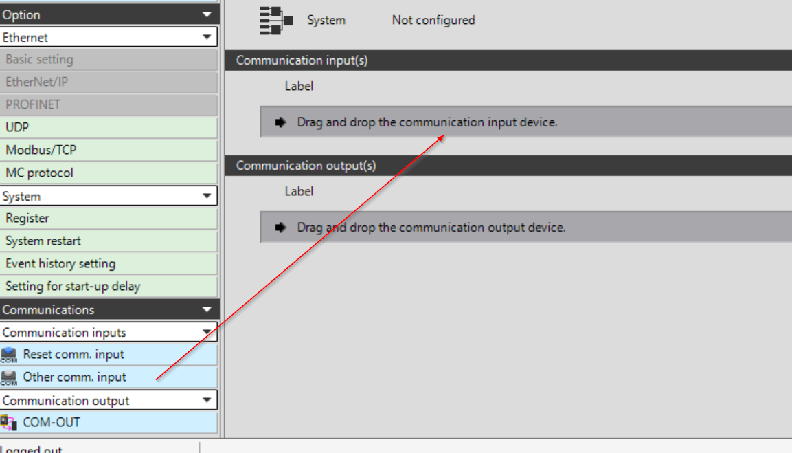
The operation is as shown in the figure below.
Done!
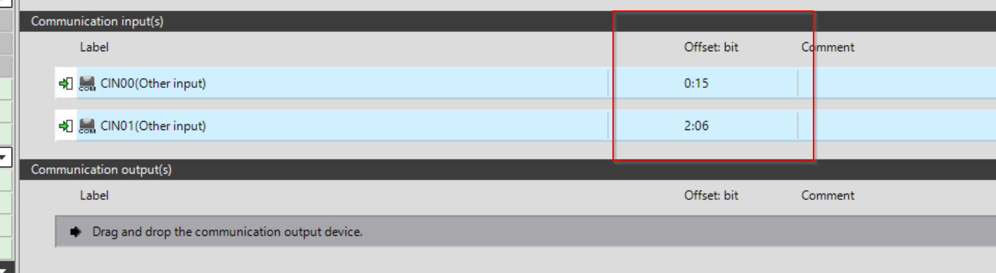
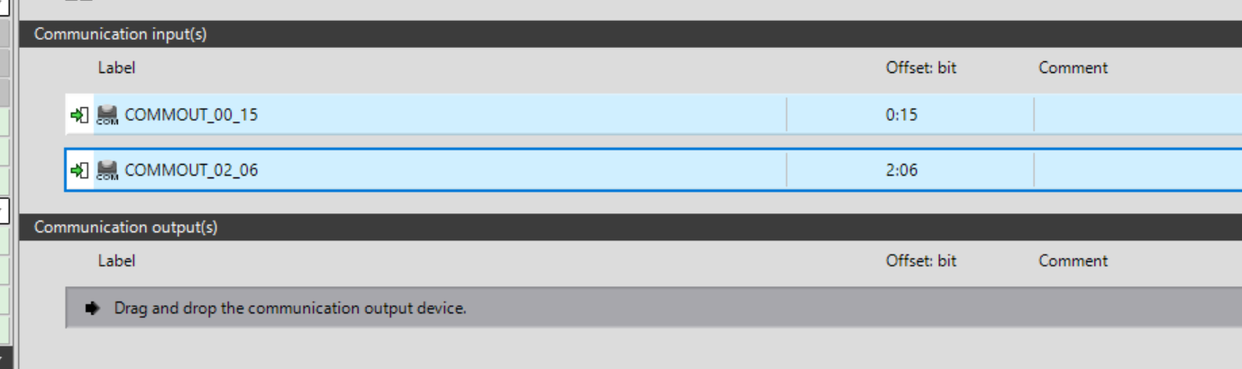
Offset Bit
Click Offset Bit and change the address number of Communication input.
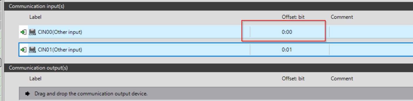
Each Comm.Input can be set to a different address address depending on the application, as shown in the figure below.
Done!
Label
Click on the Label Field in Communication Input and change the name of the variable to something easy to understand.
Done!
Communication outputs
In the Profinet Device GSDML File definition in Keyence, 32 pieces of 8Bit communication output data are already defined, and we can drop the ones we use on the GC Configurator with COM-OUT and use them in the Safety program. Any Bit data not defined in the Communication output(s) Field will be False.
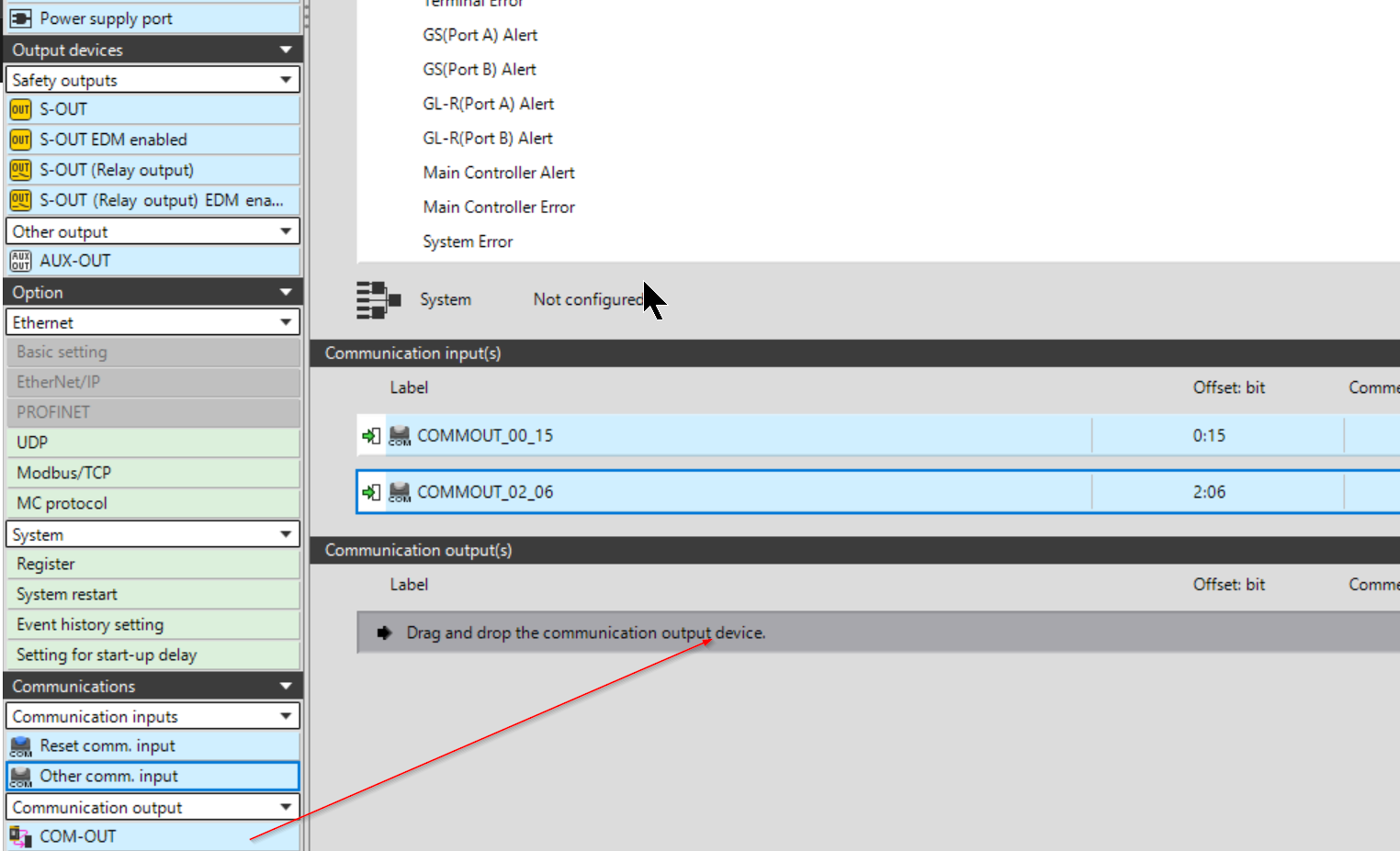
The operation is as shown in the figure below.
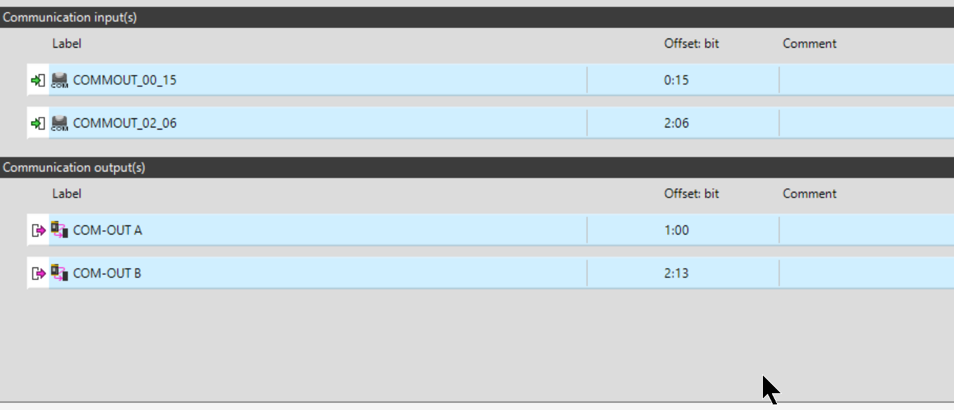
Offset Bit
Click Offset Bit and change the address number of Communication Output.
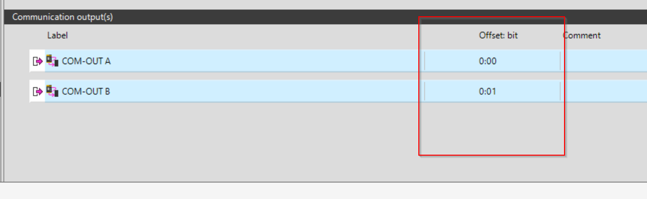
The operation is as shown in the figure below.
Done!
Label
Click on the Label Field in Communication Output and change the name of the variable to something easy to understand.
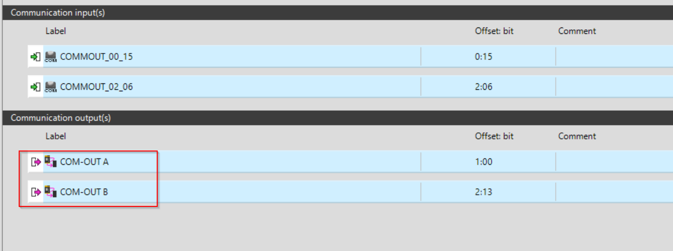
Done!
Program
Here is the safety program I created for this article. The emergency stop input signal is delayed for 1 second by a delay timer called ESTOP1, then Q is output, and the Reset Block is used to prevent the lamp from lighting unless the emergency stop signal falls once and is reset (by a reset button or a reset signal from TwinCAT). Then, when ESTOP requires a reset, the lamp will output a flashing light.
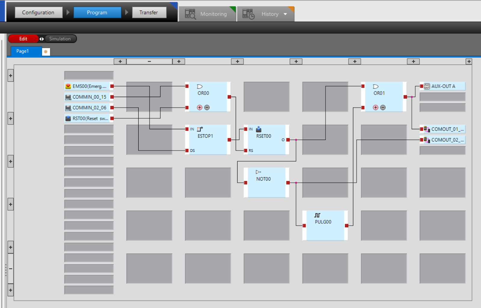
Pulse Generator
The Pulse Generator Function Block is used to generate a signal that is continuously turned on and off at specified intervals.

Reset
Reset Function Block, holds output OFF until a reset signal is received with the safety input ON. This block can be used to restart the machine.

Beckhoff Side
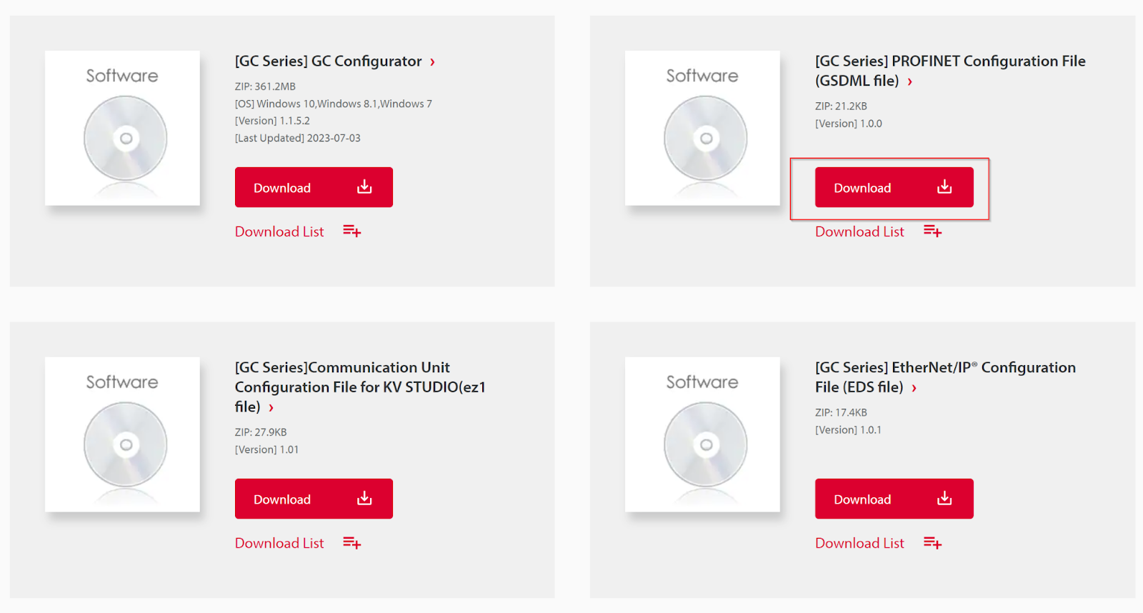
Download GSDML
There are GC1000 features available for PROFINET IO communication: If you are configuring the GC1000 for the first time using the PROFINET IO controller configuration software (in this case Beckhoff EL6631 and TwinCAT3), install the GC1000 GSDML File Please install the GC1000 GSDML File.
You can download GSDML from the link below.
Unzip the downloaded ZIP file.

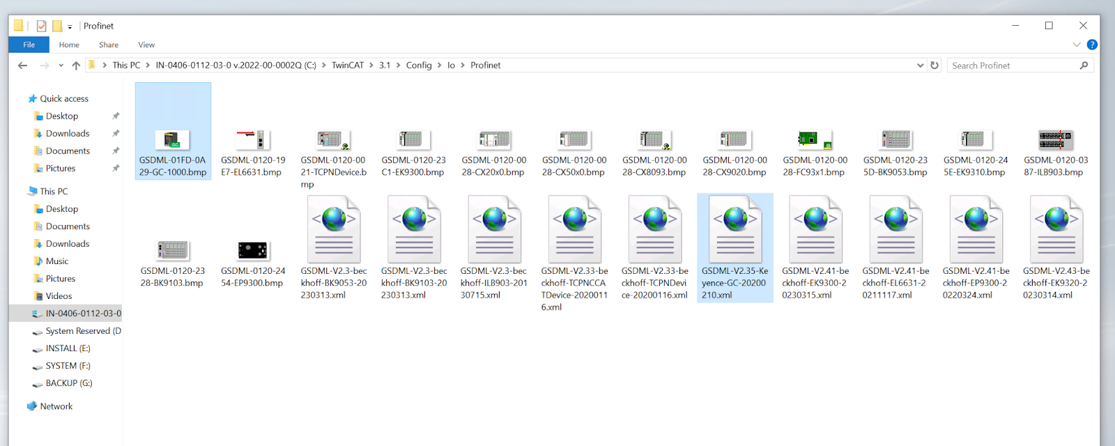
There is such an XML File.
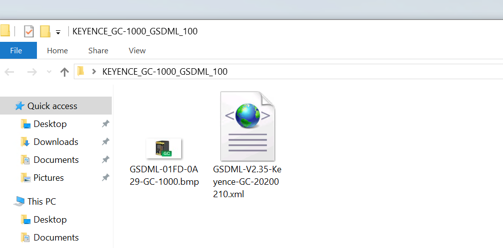
Install GSDML
Move the GSDML File to the following Path.
C:\TwinCAT\3.1\Config\Io\Profinet
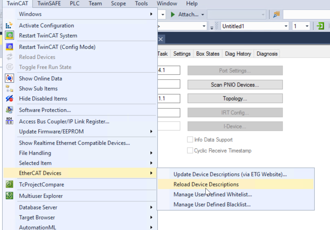
Reload Device Descriptions
Click on EtherCAT Devices>Reload Device Descriptions to reload the Device Description File.
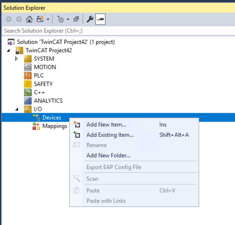
Add EtherCAT Master
I/O>Devices<right click>Add New Item.
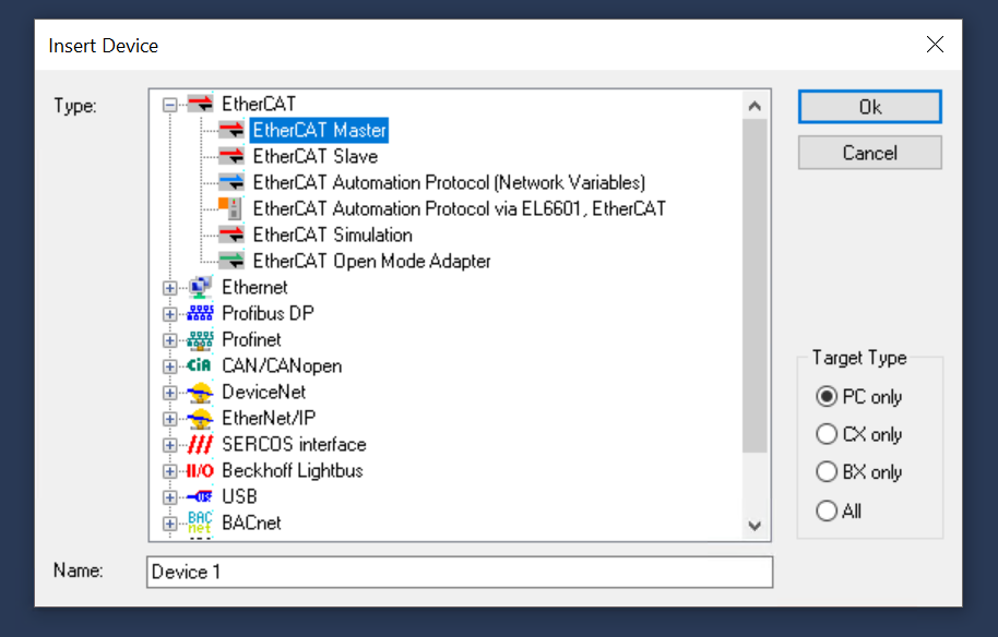
Select EtherCAT Master and proceed with Ok.
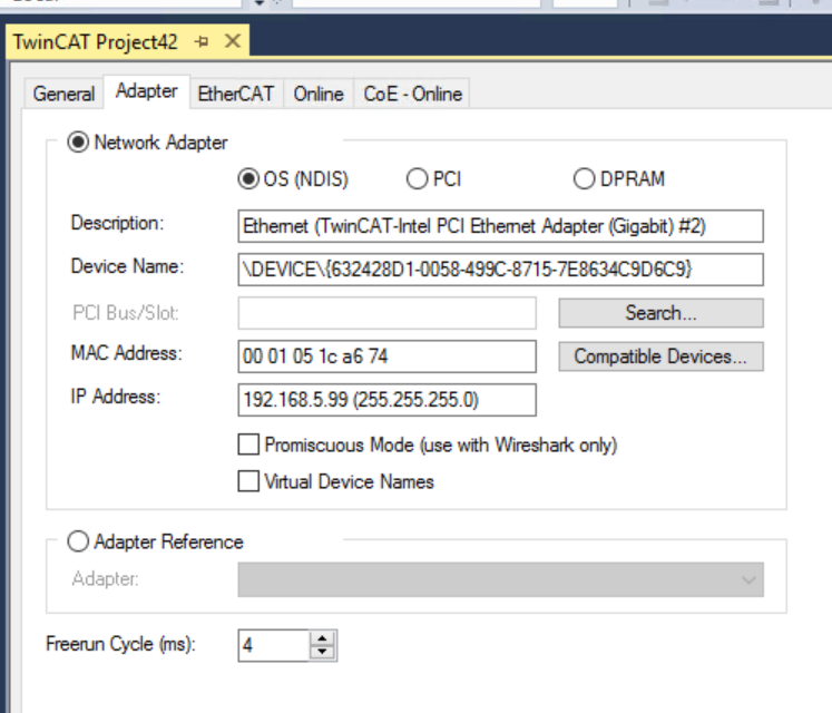
Configure the Network Adapter to be used as EtherCAT Master.
Let’s check one more time that the Adapter you just set up is correct in the Adapter Tab.
Scan
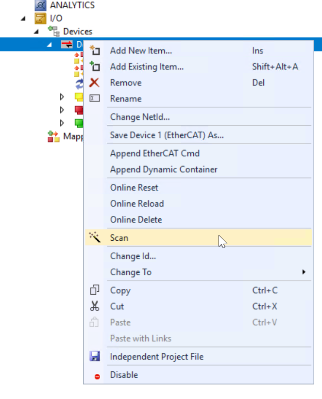
Go to Devices>Right click on the EtherCAT Master you just added>Use the Scan function and search for EtherCAT Slave.
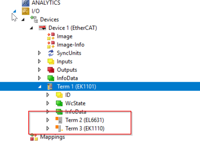
Done!The EK1101 used in this article was found.
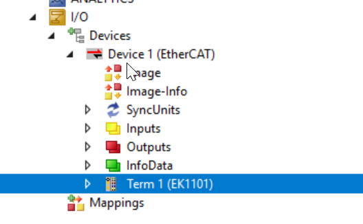
And also EL6631 is used in this article.
Add Profinet Controller
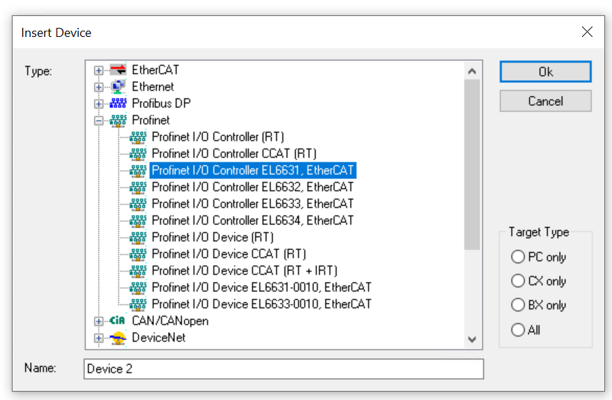
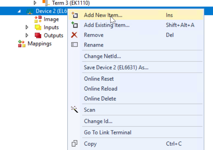
Next, go to Devices>Add New Item to add Profinet Controller.
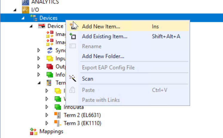
In this article, we will use EL6631, so select Profinet>Profinet I/O Controller EL6631, EtherCAT and press Ok to proceed.
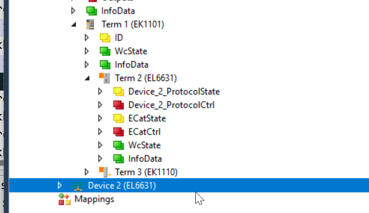
Done!A new Profinet IO Controller has been added.
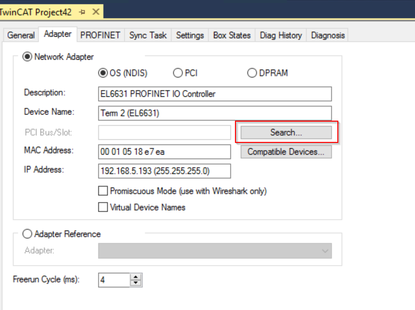
Configure Adapter
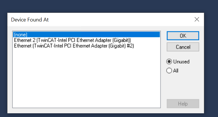
Double-click the Profinet IO Controller you just added and click Search from the Adapter Tab to search for a Network Adapter that is now available on your hardware.
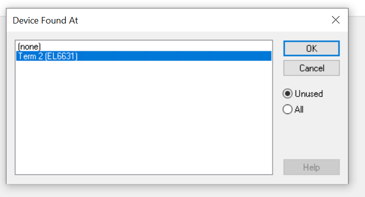
Select the EL6631 terminal obtained by using the Scan function and press >Ok to proceed.
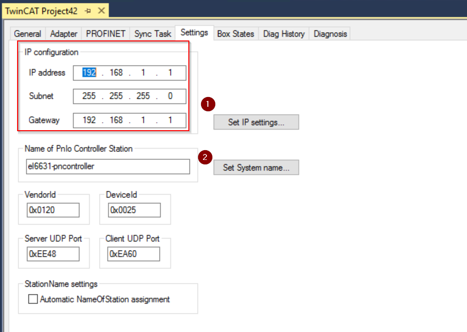
Configure Profinet Controller
Next, let’s set the IP Address and PNIO Controller Station Name from the Settings Tab of the EL6631 Profinet IO Controller Terminal.
Confiugre Task
The PROFINET Controller Protocol must always run as a Task, and the Profinet Protocol is processed in the configured Task time. Theoretically, the Controller can also collaborate via other Tasks (e.g. PLC or NC Task). (e.g. PLC or NC Task).
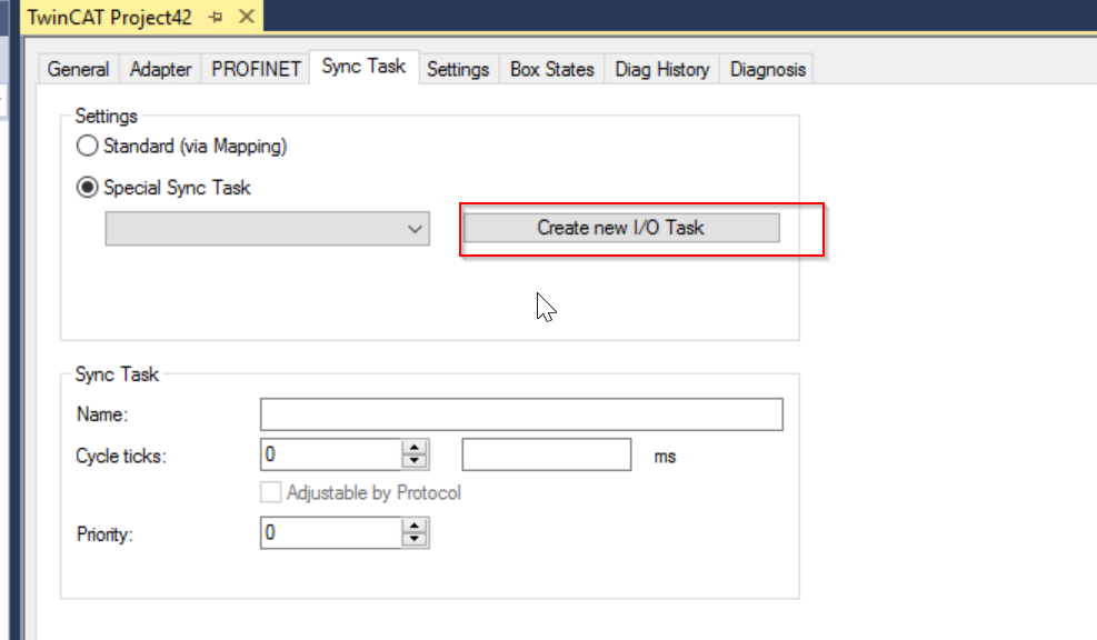
However, if Runtime is stopped, restarted, or debugged, PROFINET will also be stopped. To avoid this phenomenon, it is better to create a Free-Run SyncTask.
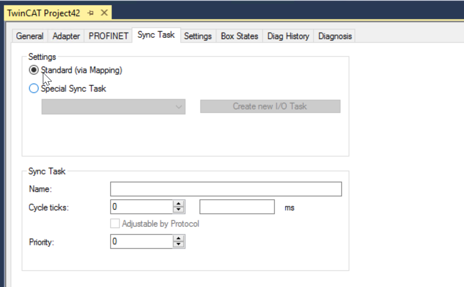
Click “Create new I/O Task” to define a new Task.
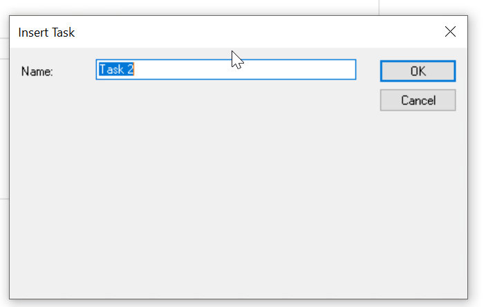
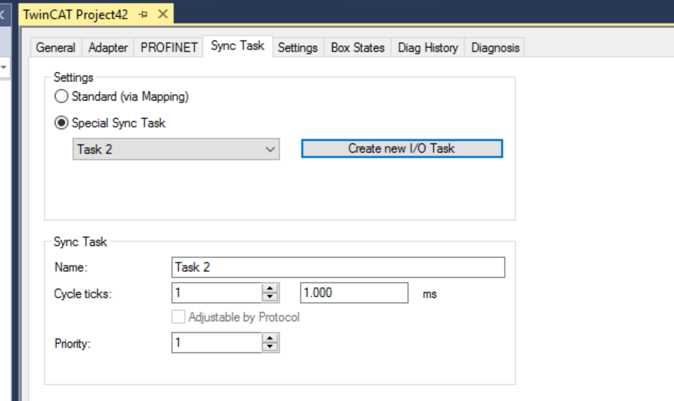
Enter a task name and press “Ok” to proceed.
The PROFINET basic cycle is 31.25 µs. This cycle is always multiplied by SendClockFactor (SCF) to get the basic cycle.
The SendClockFactor is typically set to 32 in the RTClass1. This is also the minimum PN cycle for RTClass1 in the Beckhoff PROFINET Controller, resulting in a minimum cycle time of 1 ms. In addition, it is used in combination with ReductionRatioFactor.
For RTClass1 the smallest cycle must always be doubled (permissible cycle times (for RTC1) with an SCF of 32 are 1, 2, 4, 8,…, 512)In RTClass1, The minimum cycle must always be doubled (SendClockFactor doubled (permissible cycle times (for RTC1) with an SCF of 32 are 1, 2, 4, 8,…, 512). , 512).
Add Keyence GC-1000 Profinet Devices
Next, right click on Profinet IO Controller>Add New Item to add Keyence’s Safety Controller GC1000.
Select Controller>Keyence Safety Controller>Ok to proceed.
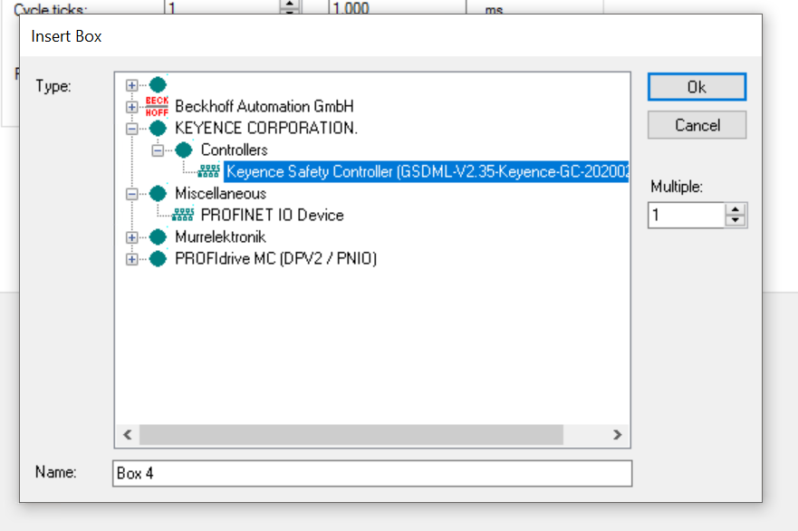
Done!Profinet IO Devices GC1000 has been added.

Configure Device IP
When establishing a PROFINET connection, the Controller assigns an IP address to the Device along with the device name (that is, if the device does not yet have an IP address or also has a different address). Before an IP address is actually assigned to the device by the Controller, ARP is used to test for possible address conflicts or to check if the device already has this IP address.
If an IP address is already in contention on the network, the IO driver determines this and outputs a corresponding message to Logger Windows.
If there is no response to the ARP, it means that no device is using this IP setting, and the controller will use DCP_SET to assign the IP setting to the device.
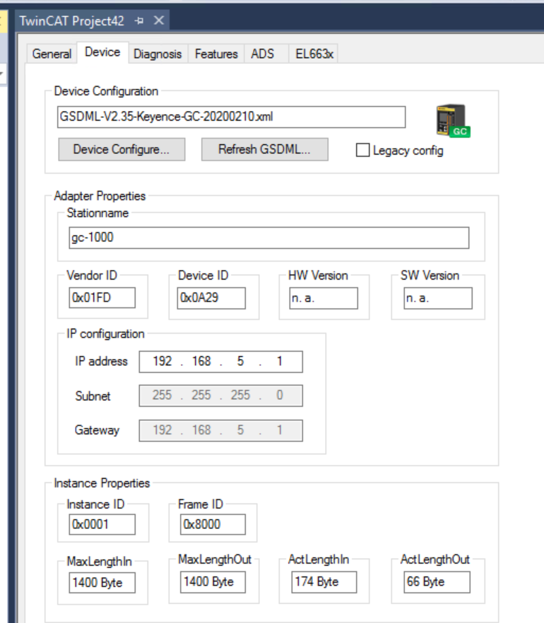
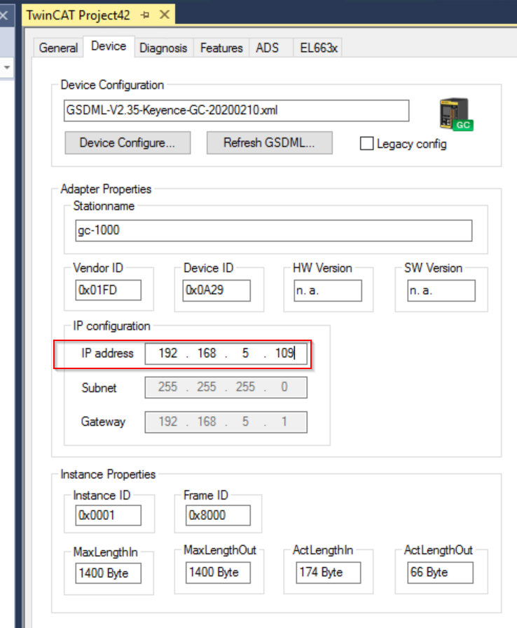
IP settings can be configured here.
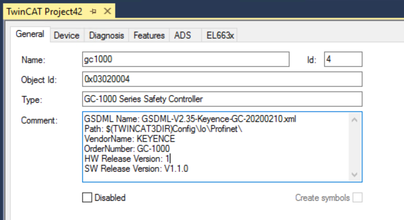
Configure Device Name
Open the General Tab and change the device name in the Name Field.
Add PLC Project
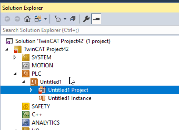
Next, click on PLC>Add New Item to add a PLC project.
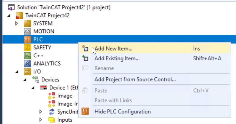
Select Standard PLC Project and Add it.
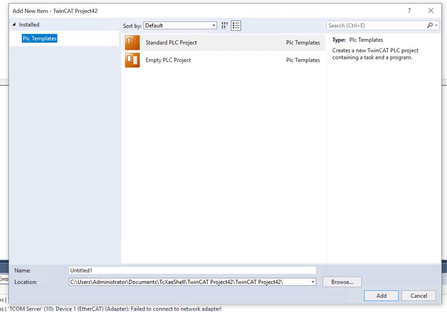
Done!
DUT
Now we will define some structures.
DUT_8BIT
This structure here defines BITARR8 (8Bit array) according to the structure of InputComm and OutputComm data of Keyence.
| TYPE DUT_8BIT : STRUCT bData:BITARR8; END_STRUCT END_TYPE |
DUT_GC1000_ErrorCode
The structure here is defined according to the 30 ErrorCode and DetailErrorCode variables in the keyence.
| TYPE DUT_GC1000_ErrorCode : STRUCT ErrorCode AT %I*:UINT; DetailErroCode AT %I*:UINT; END_STRUCT END_TYPE |
GVL
Define variables in the Global Variable List according to the Keyence GC1000 side.
| {attribute ‘qualified_only’} VAR_GLOBAL InputComm AT %I*:ARRAY[0..7]OF DUT_8BIT; OutputComm AT %Q*:ARRAY[0..7]OF DUT_8BIT; ModelInformation AT %I*:USINT; OperationTime AT %I*:UDINT; OperationStatus AT %I*:BYTE; NumberOfError AT %I*:USINT; ErrorCode AT %I*:ARRAY[1..30]OF DUT_GC1000_ErrorCode; GC1000PortA,GC1000PortB AT %I*:BYTE; PNIOState,PNIODiag AT %I*:UINT; END_VAR |
MAIN
This is the main program, which allows the Beckhoff side to send reset and delay disable signals, and also to receive the status of the GC1000 emergency stop button.
| PROGRAM MAIN VAR bReset :BOOL; bDisableDelay :BOOL; bESTOPStatusON :BOOL; bLampStatus :BOOL; bESTOPStatusOFF :BOOL; bOperationStatusRUN,bOperationStatusStop:BOOL; bOperationStatusNormal,bOperationStatusAbNormaal:BOOL; ModelInformation:USINT; OperationTime :UDINT; GC1000CommOK :BOOL; GC1000DiagOK :BOOL; END_VAR GC1000CommOK:=GVL.PNIOState=0; GC1000DiagOK:=GVL.PNIODiag=2; GVL.OutputComm[1].bData.7:=bReset; GVL.OutputComm[4].bData.6:=bDisableDelay; bLampStatus:=GVL.InputComm[2].bData.0; bESTOPStatusON:= NOT GVL.InputComm[5].bData.5; bESTOPStatusOFF:=GVL.InputComm[5].bData.5; bOperationStatusRUN:=GVL.OperationStatus.0; bOperationStatusStop:=NOT GVL.OperationStatus.0; bOperationStatusAbNormaal:=GVL.OperationStatus.0; bOperationStatusNormal:=NOT GVL.OperationStatus.0; ModelInformation:=GVL.ModelInformation; OperationTime:=GVL.OperationTime/10; |
Link Variables
Now, Mapping the PLC variables and Process Data of Profinet.
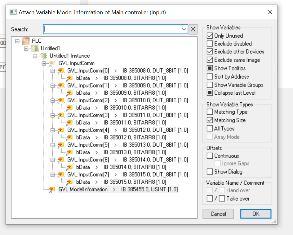
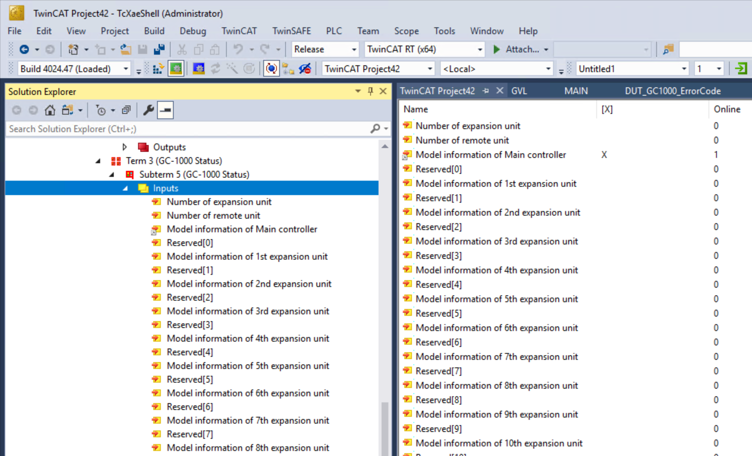
Right click on GC1000>GC-1000 Status>Model information of Main Controller>Change Link.
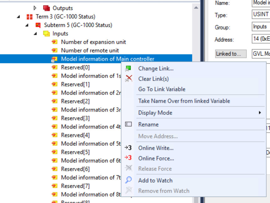
The variable you just defined in GVL will be available for selection.
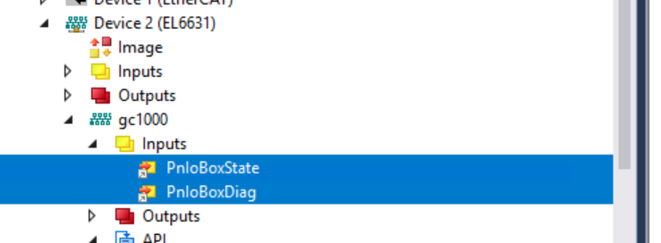
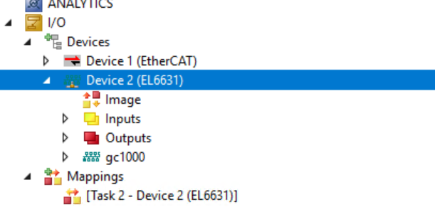
To get the communication state between GC1000 and EL6631, let’s Mapping PnIoBoxState and PnIoBoxDiag in GC1000>Inputs.
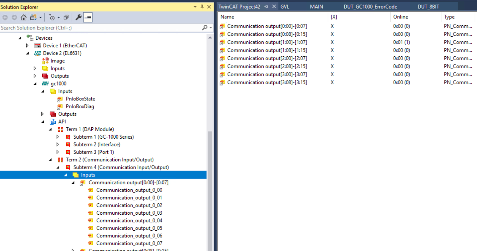
Mapping the process data of communication output in Communication Input/Output> with the variables defined in GVL.
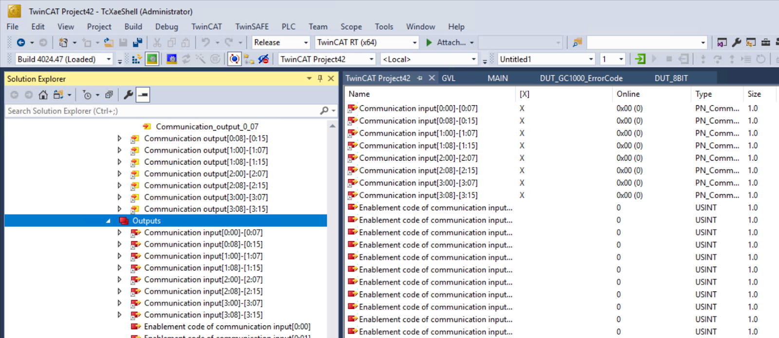
Mapping the Communication Input process data in Communication Input/Output> to the variables defined in GVL.
I will not elaborate on the other variable Mapping.
Activate
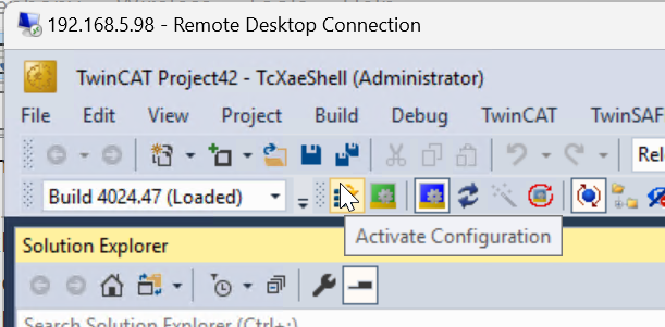
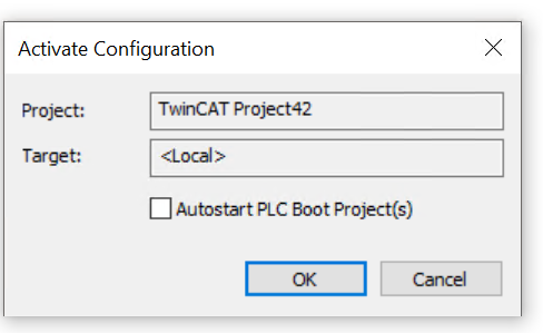
Click the Activate Configuration button to download the Hardware Configuration to Runtime.
Proceed with Ok.
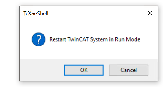
Restart TwinCAT in Run Mode with Ok.
Login
Click the Login button to download the program to TwinCAT Runtime.
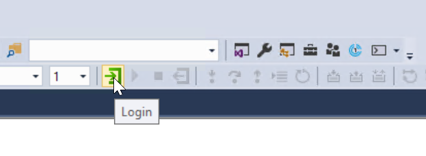
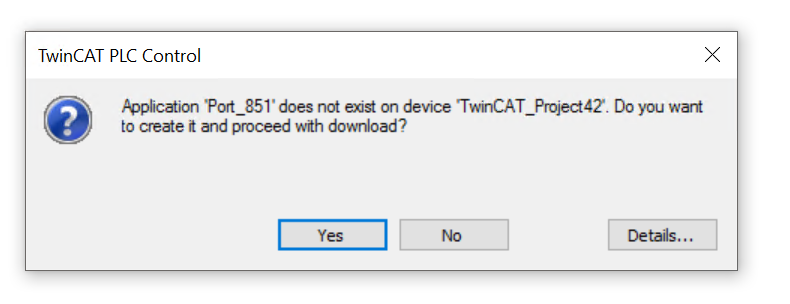
Proceed with Yes.
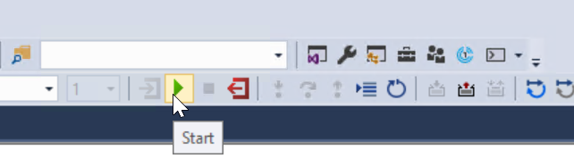
Start
Finally, click the Start button to start Runtime.
Assign Device Name
We need to assign the device name to bring up the Profinet network,please click on EL6631.
Click the PROFINET>Scan PNIO Devices button.
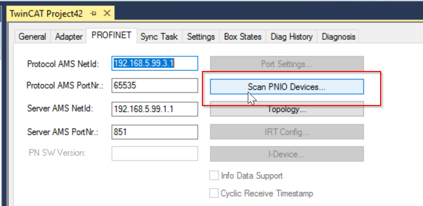
The Scan Deviecs screen appears, allowing you to search for and list devices that are now on the same network as the EL6631.
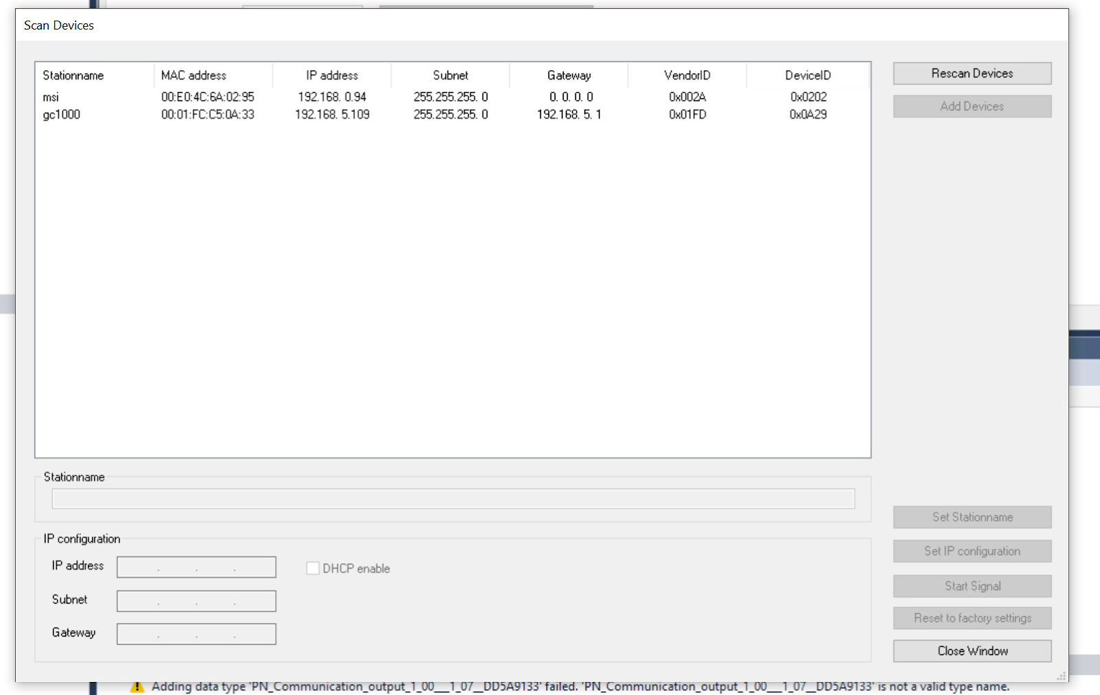
The GC1000 used in this article has been named “gc1000” in the project, so enter “gc1000” in the Stationname field and click “Set Stationname” to set the device name of the GC1000. Click “Set Stationname” to set the device name of GC1000. Then click “Set Stationname” to set the device name of GC1000.
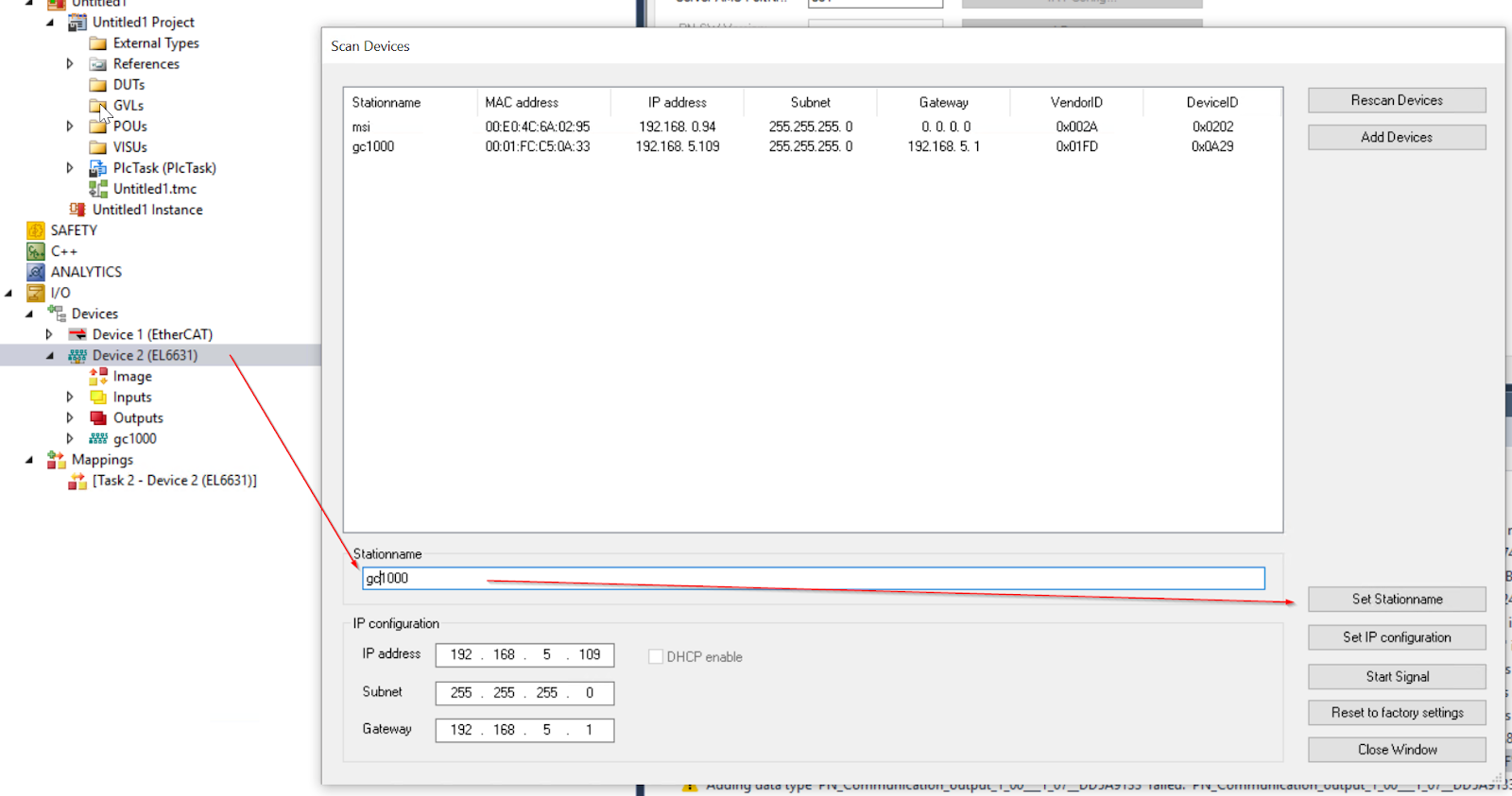
Done!Next, click on the Set IP Configuration button and set the IP address of the GC1000.
Result1‐ Error
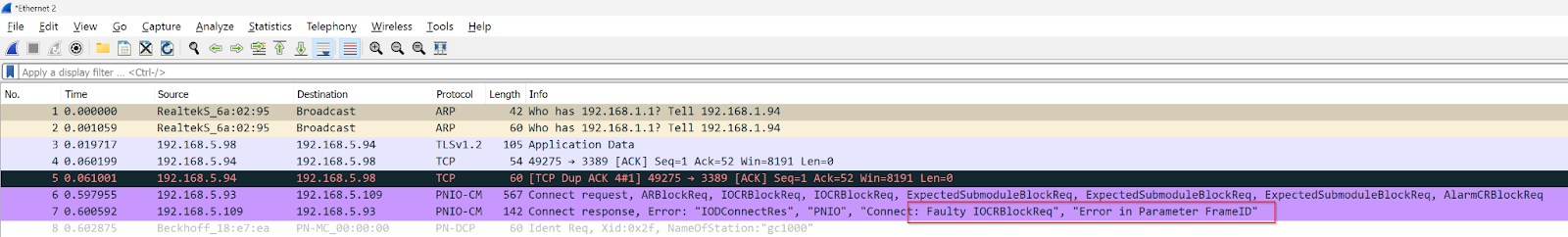
However, Profinet communication between GC1000 and EL6631 could not be established, and when I checked Packet from Wireshark, I found a message “Error in Parameter Frame ID” in Package of PNIO-CM.
Click GC1000 and open the Device Tab.
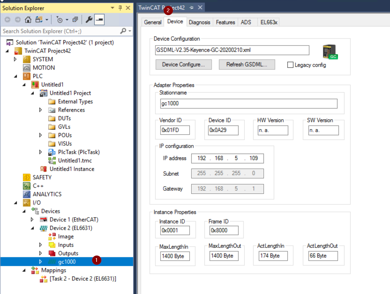
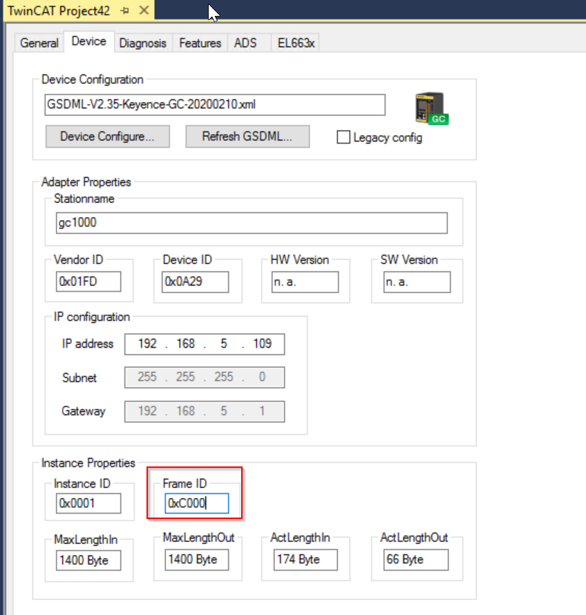
“InstanceID” and “FrameID” can also be changed on this screen, but the default settings are Ok for most basic applications. But there are some exceptional cases. (For example, Unicast for RTClass1 is 0xC000 to 0xFAFF)
In this article, FrameID is set to 0xC000.
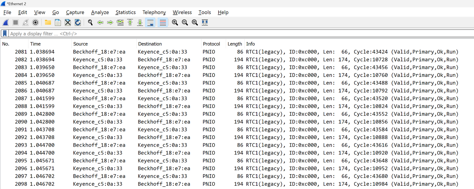
Result-2 OK
Done!You can find the PNIO packets in Wireshark.
This video shows how to reset the GC1000 signal from EL6631 via Profinet.