This is the third episode of the Opto22 groov CPU Tutorial. This time we will explain the MMP Memory Mapping concept of the groov CPU, then convert from MMP addresses to Modbus TCP, and finally I will show you how to access IO module data via Modbus TCP.
Let’s get started!
MMP?
OptoMMP is a memory mapping protocol based on the IEEE1394 standard. We can use this protocol to create software applications for remote monitoring, industrial control, and data collection using Opto 22 hardware products.
Accessing over the internet…
Opto 22 Ethernet-based devices are like any other hardware on an Ethernet network and can be accessed via the Internet in exactly the same way that you access your computer. However, it depends on the network and Internet connection you are currently using and must be adapted by your system administrator, network administrator, Internet Service Provider (ISP), etc.
CAUTION!
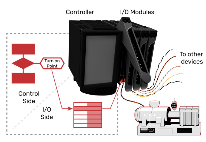
If you are communicating directly with the Opto22’s memory map device, make sure you are not causing conflicts with other communication options. For example, if you are using a memory map to exchange data with an I/O unit, and that I/O unit is controlled from the Codesys Runtime, this is fine if you are getting input data, but be careful if you are writing output data.
In other words, make sure that data written directly to the I/O side does not conflict with the control logic being executed in the main control program.
THE MEMORY MAP?
I will now explain a brief knowledge of Memory Mapping.

If you’re a programmer
You may also think of a memory map as being a data structure that matches a set of physical and logical addresses of read-write memory on a device. In a nutshell, think of it like a lookup table.
If you are familiar with PLCs, you can imagine a Memory Map as a PLC register.
In the Opto22’s Memory Map device, a physical address may hold a single value of data, such as When data is written to the Memory Map, the memory-mapped device responds by returning a packet indicating a success or failure code.
And when a read is performed, the memory-mapped device returns a packet containing the data.
If you’re not a programmer
A memory map (sometimes called a mem map) can be thought of as a set of zip codes. Each mailbox address has a different owner, who either has information that he or she wants or wants to change.
To retrieve or change information, a message is sent to the child postal code. For example, to retrieve the part number of a device, a data packet is received for that address FFFF F030 0080.
It can also both write and read data to a memory map. (e.g., to change the configuration, state, or value of an I/O channel).
groov I/O Units
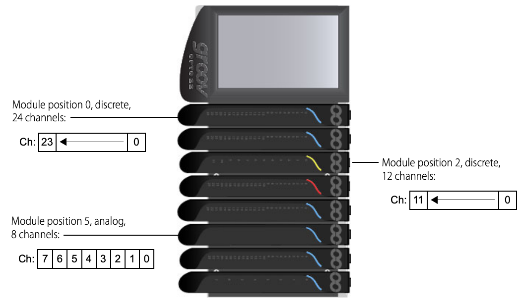
The I/O units in the I/O processor of the GRV-EPIC-PR1 or GRV-EPIC-PR2 are called groov I/O units, and the groov I/O chassis can house 4/ 8 or 16 I/O modules. Each module contains from 8 to 64 channels, depending on the module.
The figure below also shows an example of how channels are identified in some modules.
Using the OptoMMP Protocol
As I mentioned earlier, the communication using the OptoMMP protocol basically puts IEEE1394 packets inside TCP/IP or UDP/IP packets.
And the OptoMMP port number is 2001 by default on the device (this port number can be changed at address F030004).
こちらはTCPの例のようになります:
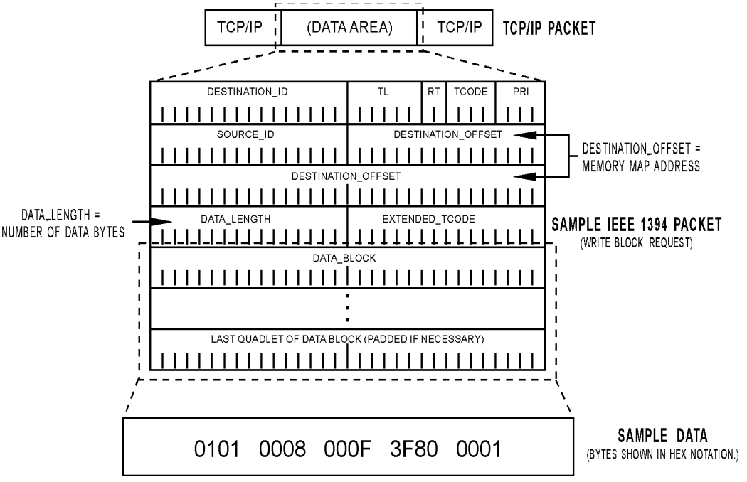
The Opto22 memory-mapped device uses the following types of request packets as specified in the IEEE1394 standard.
- Read Quadlet:Read 4 bytes starting from a certain address.
- Read Block:Read N bytes starting from a certain address.
- Write Quadlet:Writes 4 bytes starting from a certain address.
- Write Block:Writes N bytes starting from a certain address.
To initiate communication with the memory-mapped device, the Host sends one of the following four packets via TCP/IP or UDP/IP.
Finally, it returns a read or write response packet from the device.
Writing Data
To change the configuration or status of an I/O channel, enable a counter, or write other data, the Host sends a Write Request packet containing the destination address and the new data to be written. The device responds by returning a Write Response packet indicating success or failure.
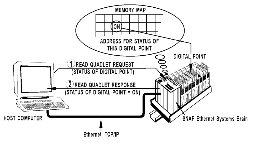
Reading Data
The Host can also access I/O module status, counter values, and other data by reading memory locations from the memory map; the Host simply sends a Read Request packet requesting data from these memory locations, and the device returns the data in a Read Response packet and the device will return the data.
Streaming Data
Most communications require a two-step operation: request and response, but some Opto 22 memory-mapped devices can also stream data. Streaming uses UDP and does not require a response.
Reference Link
Implementation
Enable
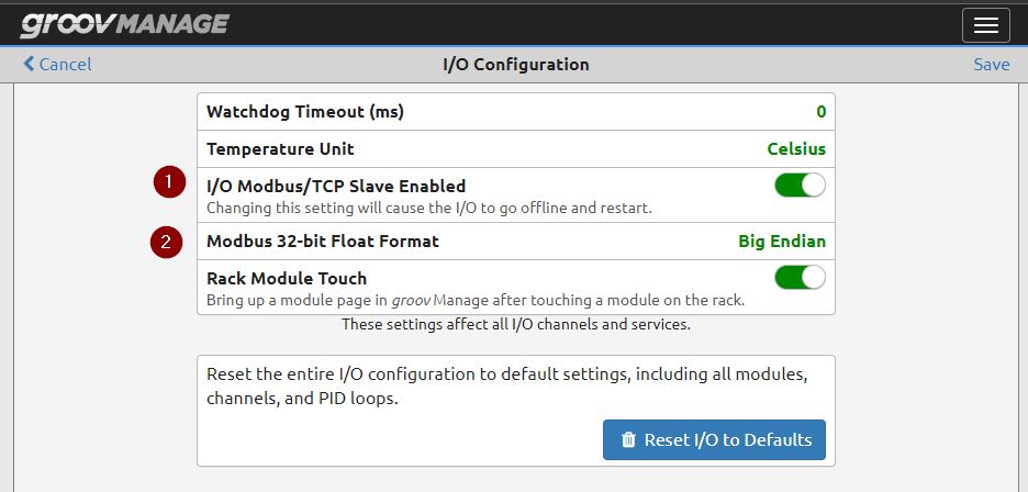
To access groov from Modbus TCP, first make sure that the I/O Modbus Slave functionality is enabled.
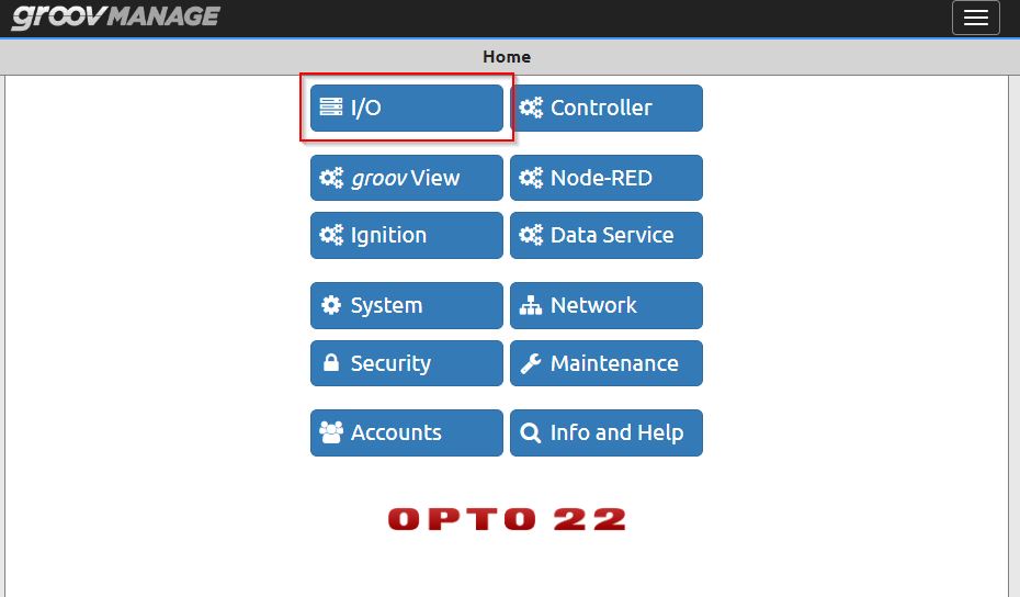
This screen actually lists the modules installed on groovCPU, Let’s click on I/O Services to proceed to the next menu.

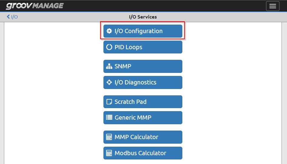
The I/O Services screen is displayed.
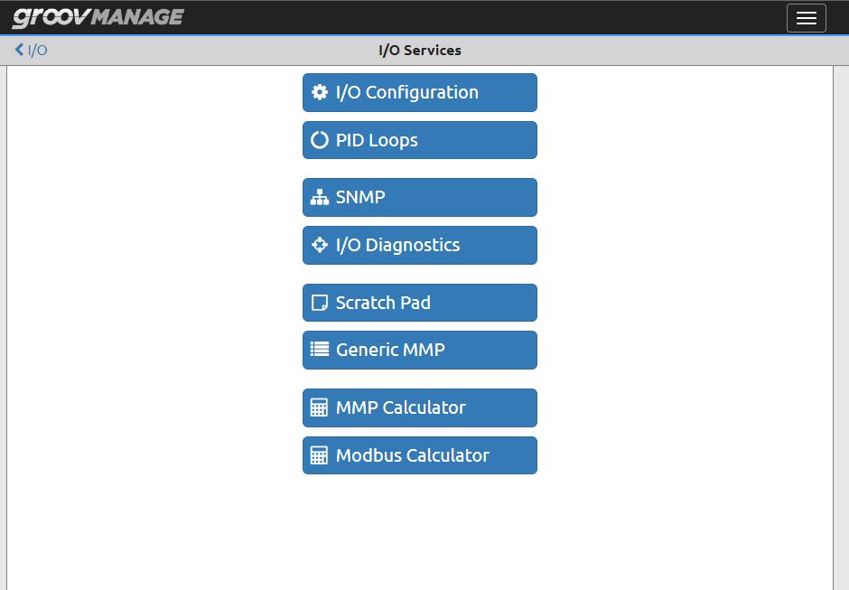
Click on I/O Configuration and proceed to the next menu.
Check if the I/O Modbus/TCP Slave Enabled function is enabled. Also, the Big/Small Endian Format differs depending on the type of CPU, so be sure to use the format that best suits your actual application.
MMP Calculator
There are several important parameters for Server Slave communication with Modbus TCP.
- IP Address
- Port:Use 502 by Default
- Modbus Unit ID:we need to find it
- Register番号:we need to find it
- Data Format:we need to find it
We will now show you how to check Modbus Unit ID、 Register number and Data Format.
Click on MMP Calculator.

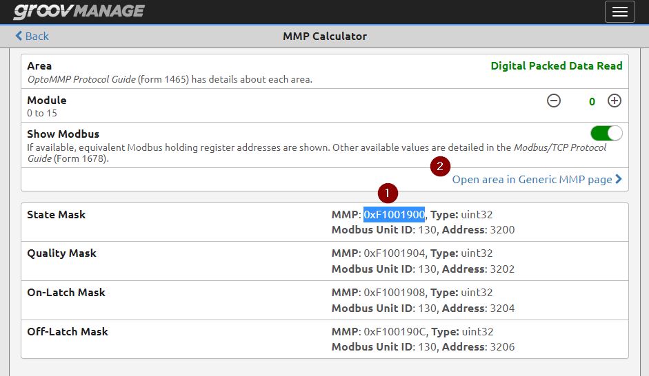
The MMP Calculator is a very useful tool that converts the MMP address of the IO module installed in the actual groovCPU to Modbus TCP Format.
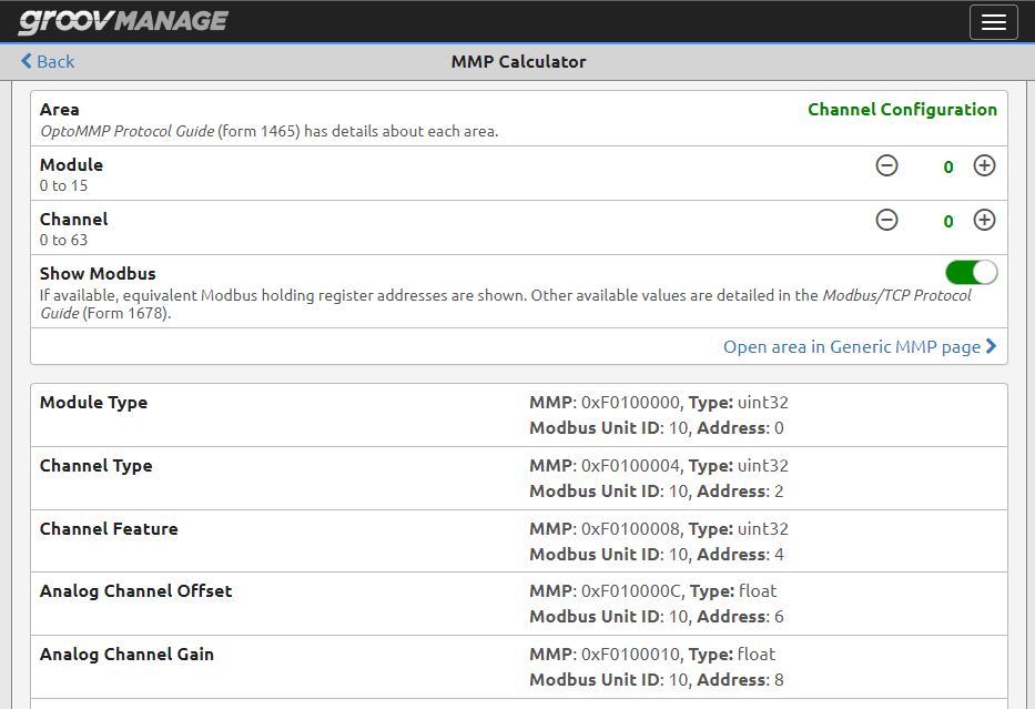
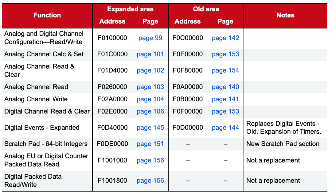
Area
You can set the items you want to check at the Area.
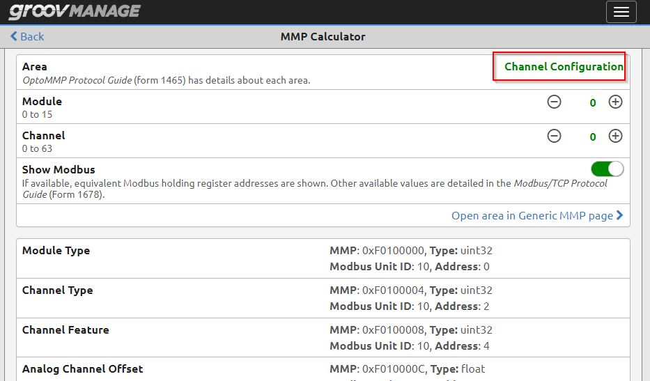
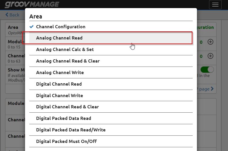
When you click on Area, not only Channel Configuration is shown, but also various access items such as Analog Channel, Digital Channel, etc.
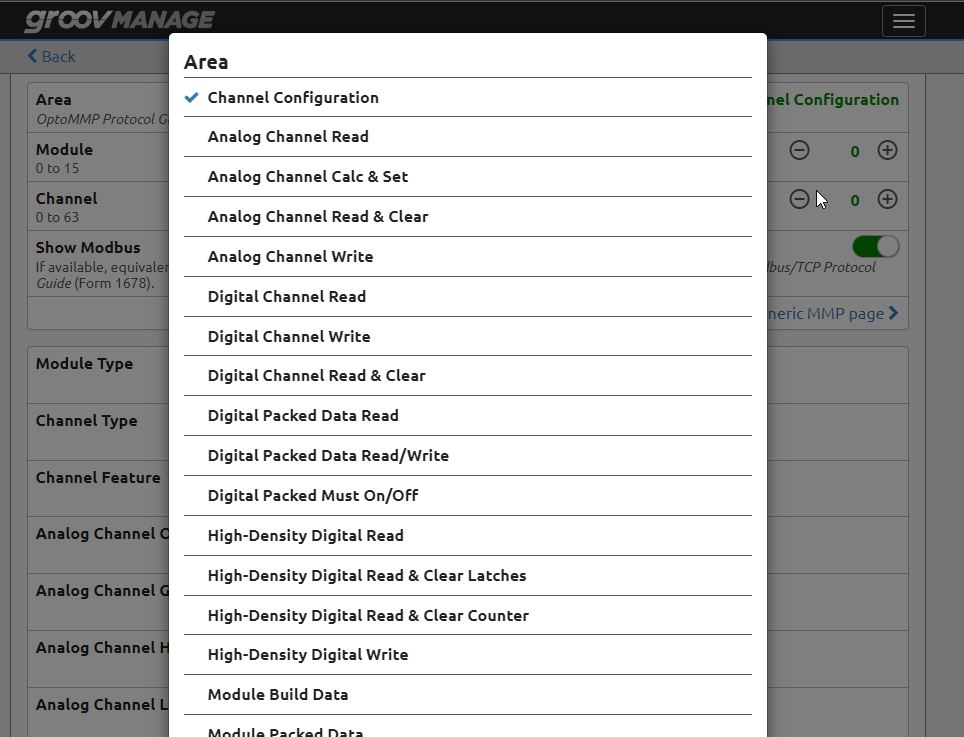
Since what we have in Slot 0 is a digital input, let’s click on Digital Packed Data Read.
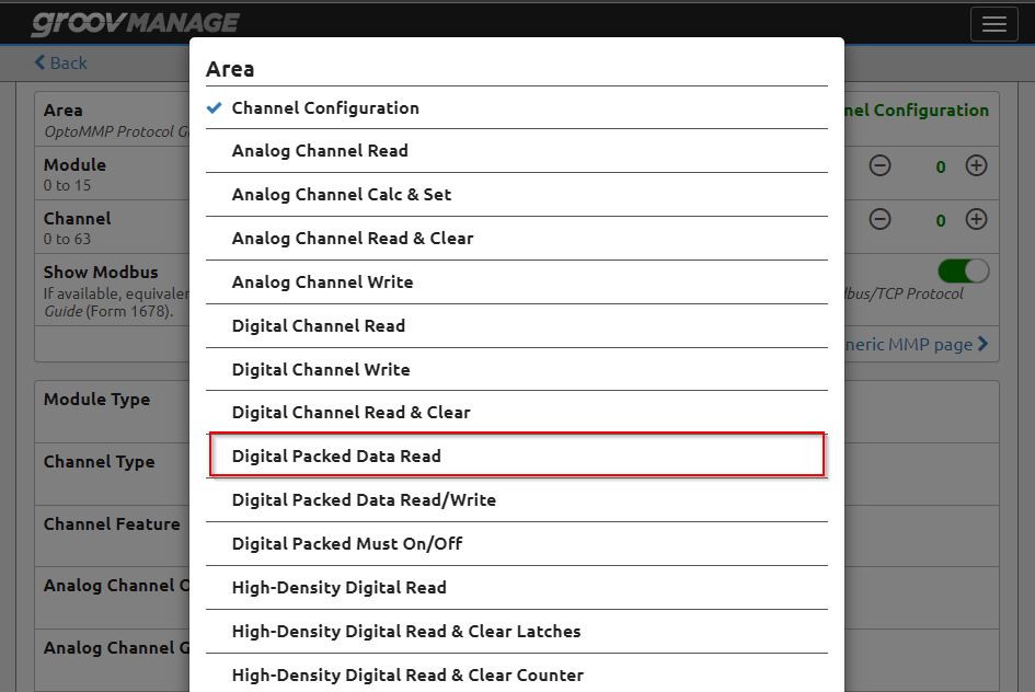
Done! Now it has changed to MMP>Modbus Address Translation Map for Digital Packed Data Read.

Module
Next we can configure the Module. As I said in the last Tutorial, groov starts with Slot0, so you can think of it as Slot0 for Module0, Slot1 for Module1, and so on.

The +/- buttons on the Module allow you to change the Slot you wish to examine.
Show Modbus
This is a button to let you to show or hide the Modbus address of the corresponding Module.

Just like this.
Data
いまAreaがDigital Packed Data ReadでModule0のデータを取得しています。
MMPの下にはModbus Unit IDとAddressがありますね。
Modbus Unit IDはModbus ClientがgroovとModbusで接続するときに必要なIDとAddressはRegister番号になります。Now Area is getting data from Module 0 with Digital Packed Data Read.
Under MMP, there are Modbus Unit ID and Address.
The Modbus Unit ID is required for the Modbus Client to connect with groov via Modbus, and the Address is the Register number.

Generic MMP
But we may not be sure if this Modbus Unit ID and Address are really correct. groov also has a tool called Generic MMP.
Test(Slot0,Digital Module)
Copy the MMP in the State Mask and click on “Open area in Generic MMP Page”.
Generic MMP is a useful tool that allows you to enter an MMP address and see the current value of the corresponding address.Paste the MMP you just copied into Address.
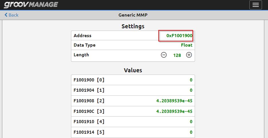
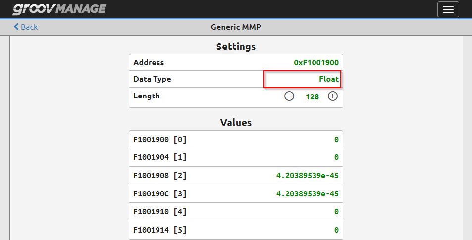
Next we need to set up the Data Type, which allows you to set how groov will represent the data for that address.
This time, we will set it as 32-Bit Integer.

Legth is the setting of how many consecutive address data of this Data Type are read from Address.
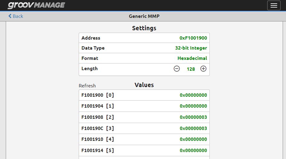
Result
Thus, the input status of Slot0 can be checked directly.

Test(Slot3 Channel0 ,Analog Module)
We can test the analog input module in Slot 3 by selecting Analog Channel Read from the Area.
Set Module=3 and Channel=0. Now the MMP for analog channel 0 of Slot 3 is displayed, and the MMP is copied to the Generic MMP tool.
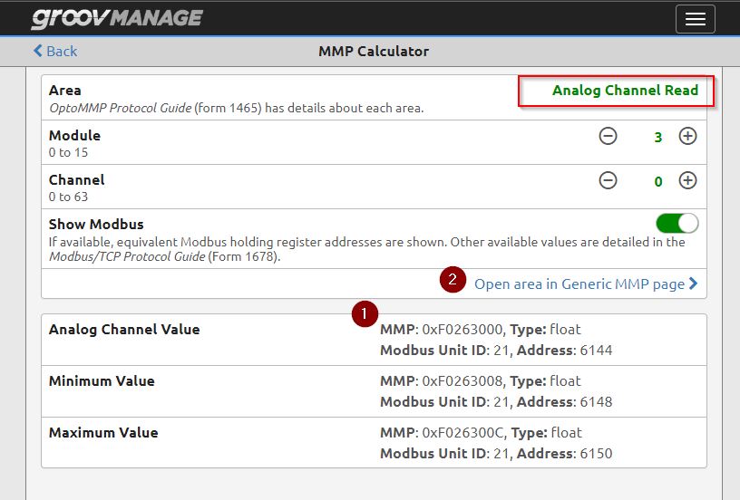
Lets set the Data type as Float.
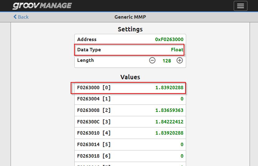
Result
Done!You have read the analog input value of Slot3 Channel0.

Test(Slot2 Channel0 ,Temperature Module)
Now let’s access the Channel 0 data in the Slot2 Temperature Module.Leave the Area as Analog Channel Read, set the Module number to 2, and set the Channel to 0.Copy the MMP ID displayed in the Analog Channel Value field and click “Open area in Generic MMP page” again.
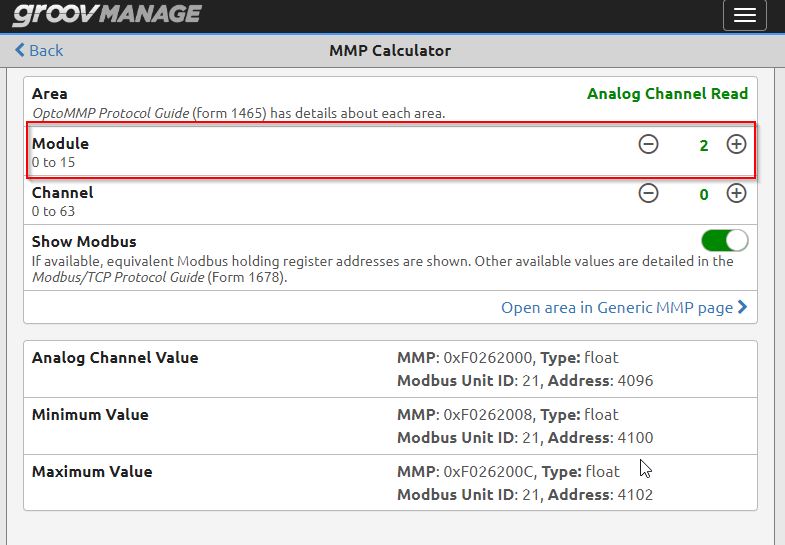
you can see the current value of F0262000 appears to be 24.85 degrees.

This is the actual operation.
Codesys
Now that we have obtained the Module data from the Generic MMP tool, the next step is to launch the Modbus TCP Client from Codesys and try to get the data of these modules.
Add Device
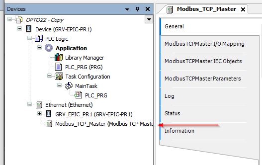
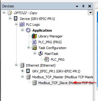
Start the Codesys project according to the previous Tutorial and go to Ethernet>Add Device.

Select Fieldbus>Modbus TCP Master>Modbus TCP Master>Add Device to add.

Confgiure Modbus
If you need to change Defaut’s communication settings, double click on the Modbus TCP Master you just added.
Add Device
If you need to change Defautl’s communication settings, double click on the Modbus TCP Master you just added.
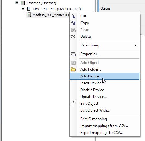
Select Fieldbus>Modbus>Modbus TCP Slave>Modbus TCP Slave>Add Device.
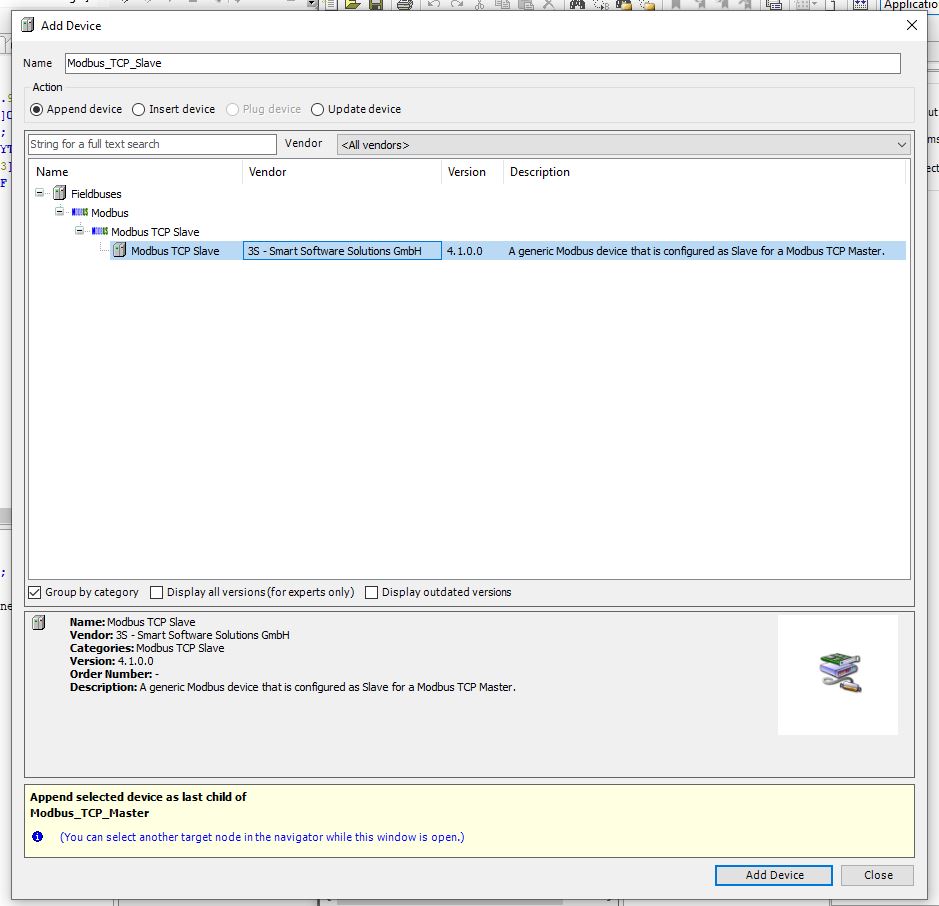
Done!Next, double-click on “Slave” for detailed settings.
Slave IP
Set the IP and Port of the Modbus TCP Slave in General>Modbus TCP>Slave IP address.
The IP of groovCPU is 192.168.5.170 and Port is 502.

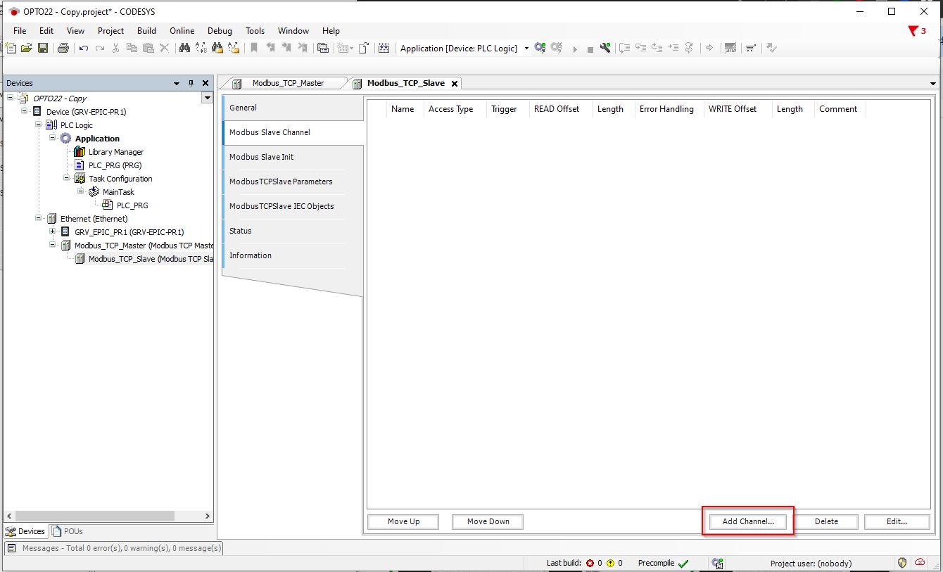
Add Chanel
Open Modbus Slave Channel and go to Add Channel to add the Register to be accessed.
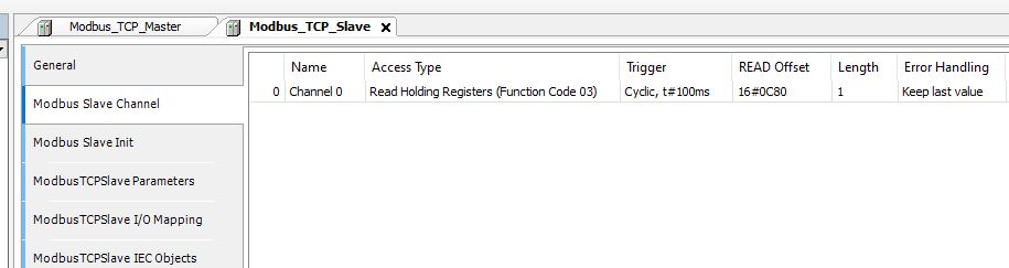
Let’s configure the Offset is 0xC80, Length=1, and Access Type is set to Function Code 3.
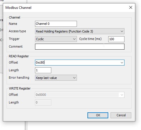
0xC80=3200Dec, which is Address=3200 if the MMP Calculator calculation was used earlier.
In other words, you are accessing the data in Digital Packed Data Read, Module0.
Done!
Update Time
The default is to not update variables that are not mapped or used in the program, so set ModbusTCPSlave I/O Mapping>Always Update Variables to Enable2.
This will ensure that variables will always be updated for Mapping and other purposes.

Unit ID
Next, we need to change the UnitID: Go to ModbusTCPSlave Parameters>UnitID Default=255.
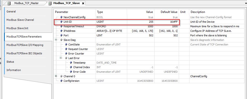
Change UnitID to 130.

That’s because the MMP Calculator just confirmed that the Modbus Unit ID is 130 when Area=Digital Packed Data Read and Module=0 is to be accessed.
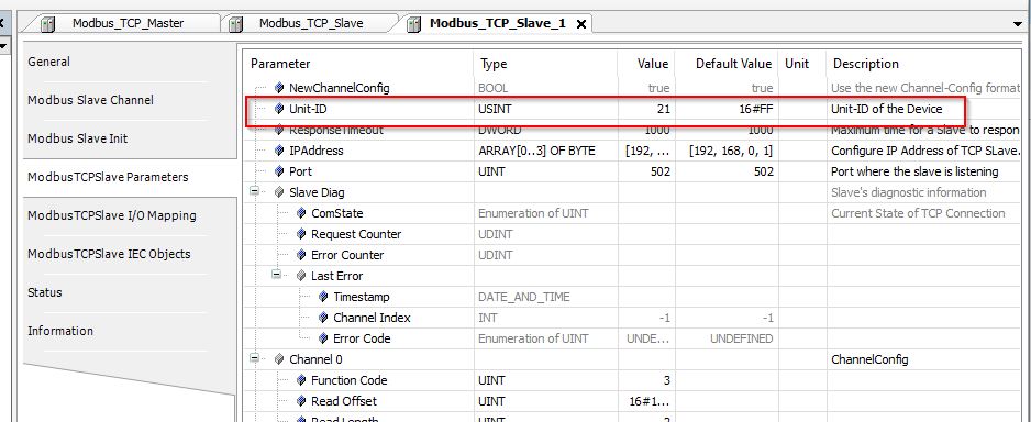
Add One More
Add another Modbus Slave and set IP and Port to the same settings as before.
Set Offset=0x1800 (6144), Length=2, and Function Code=3.
This time, Module=3 and Channel0 of Analog Channel Read will be accessed.

Unit will be 21.
Program
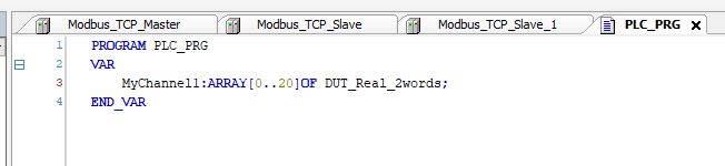
The last step is to create a program to convert Modbus TCP Slave data with Length=2 from array Word to real (Real) numbers.
Add DUT
Go to Application>Right click>Add Object>DUT.
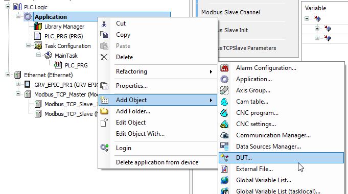
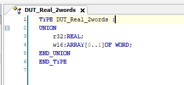
Enter the Data Unit Type name and select “Union” for Type, which means that all variables defined in the DUT will have the same Memory Offset.

Let’s define a variable of r32 and a Word array of w16.
The next step is to define variables in the MAIN program that use the DUT defined earlier.
Open MdobusTCPSlave I/O Mapping and click the … button next to Variable to perform the mapping.
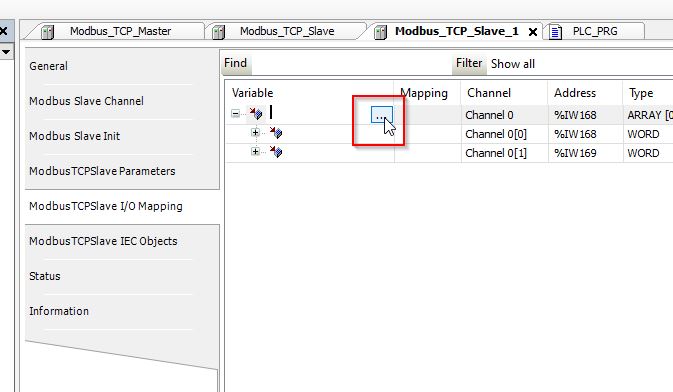
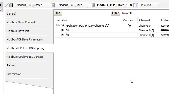
Let’s Link the variable defined in the MAIN program.

Done!
Result
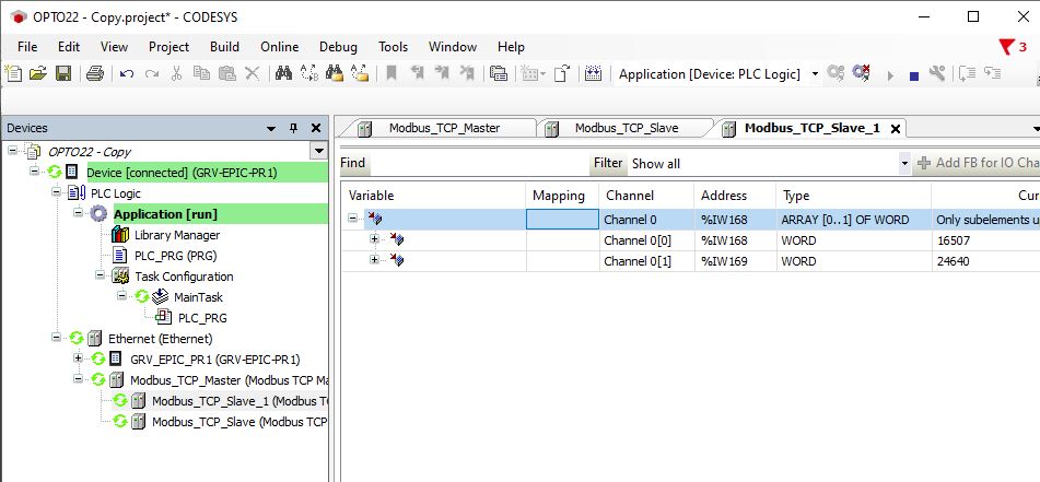
Download your project to Codesys Runtime. You will know it is working if all Fieldbus are also green.

When you operate the buttons connected to the digital input module, the data is reflected properly.
Next, let’s check the analog input module.

But..
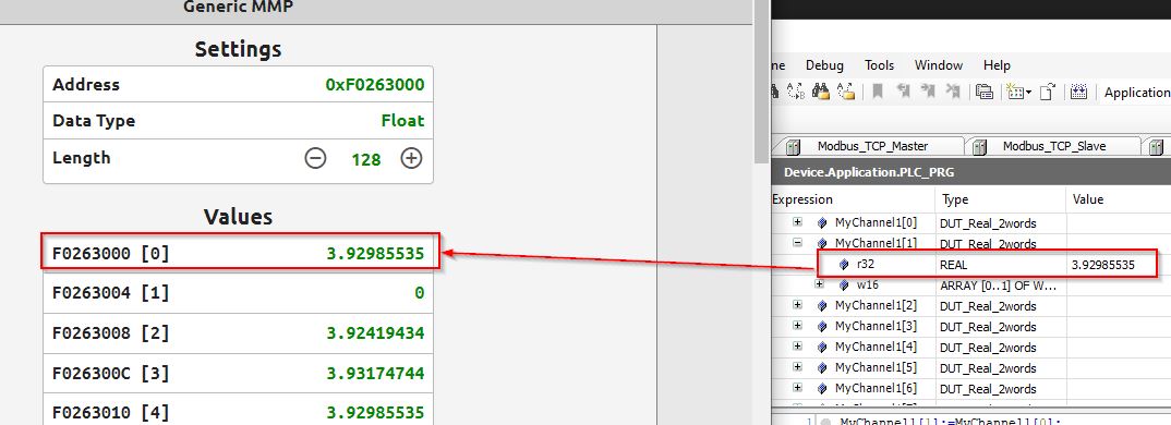
you may see from the Generic MMP tool that the data is different from the data obtained from Codesys.
Modify
Edit the program and SWAP Byte0 and Byte1.
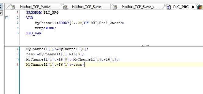
Done!The current value was read accurately.