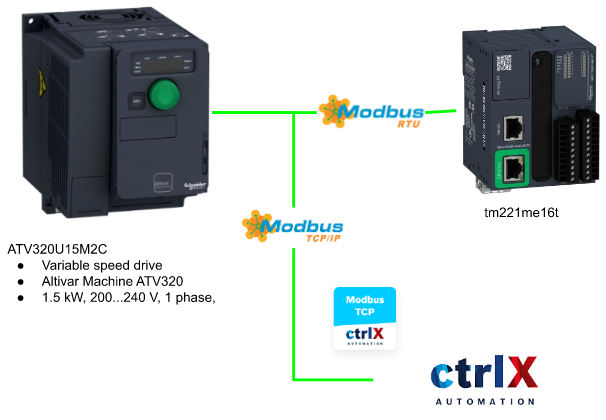
In the last tutorial, we used ModbusRTU and Drv Object Inside TM221 to control ATV320 Drive.This time I will build a Webvisu from Codesys – inside Ctrlx PLC Engineering to operate it from web server base HMI. Let’s Start!

Implementation
Here is the Implementation – Modbus TCP App is used in the Ctrlx Automation and a Webvisu from Codesys – inside Ctrlx PLC Engineering to finish this task.
Reference Link
TM221 Side
Modbus TCP Configuration
Go To Configuration Tab>ETH1>Modbus TCP and you can see the Modbus TCP Configuration Screen.
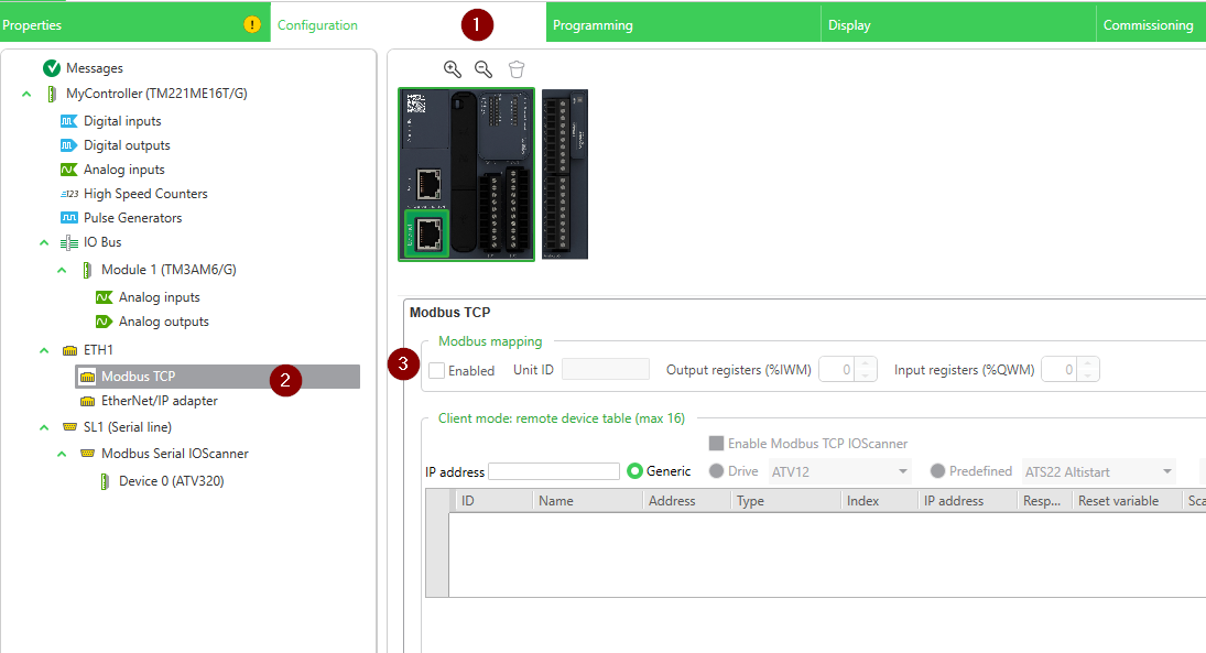
Modbus TCP Screen is shown and You can configure the UnitID and total numbers of the Output/Input Registers.
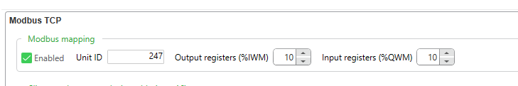
The Default value is 10 and there are 10 16 bits Registers, configured in your project.
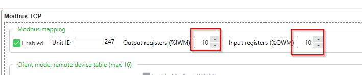
In this tutorial, I changed it to 20.There are 20 16 bits Registers, configured in your project.

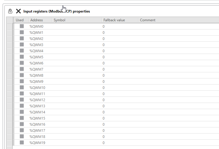
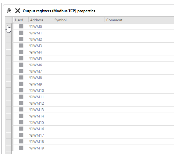
Go to the programming Tabs>Tools Tab>Network Object, you can find the Input/Output Register of the Modbus TCP.

As we configured 20 Input Registers, from %QWM0 to %QWM19 can be used in your project.
As we configured 20 Output Registers, from %IWM0 to %IWM19 can be used in your project.
Programming
In this tutorial, there is no big goal on the programming parts – and you just need to transfer the status/Command between Input/Output Register and user variables.
How to bitaccess?
Here is a small tip for you on how to access bit data in a word.
For this example, you are accessing the bit0 of %QWM1.
| %QWM1:X0 |
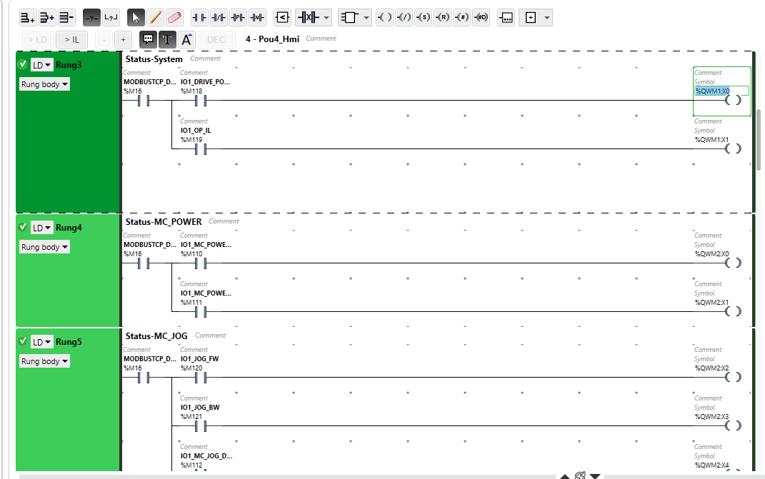
Pou4_HMI
Pou_HMI is a new Pou to transfer the status/Command between Input/Output Register and user variables.

Transfer Status to Input Register
From Rung0 to Rung10, The Status of Drive/CPU are transferred to Input Registers.
Data From Output Register
From Rung12 to Rung16, the commands received from Output Registers are transferred to user variables.

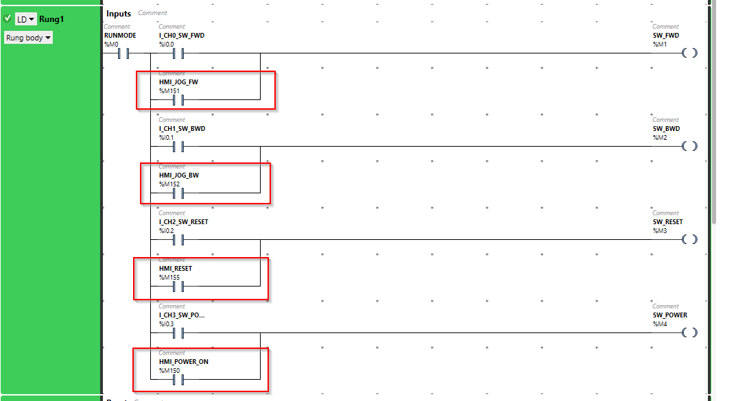
Pou1 System Modification
We only need to modify the Rung1 to let the task be triggered from these commands.
Ctrlx Side
Modbus TCP Apps
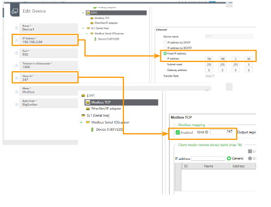
Add A Modbus TCP Slave and Configure the IP/Ports/Slave ID..Etc.
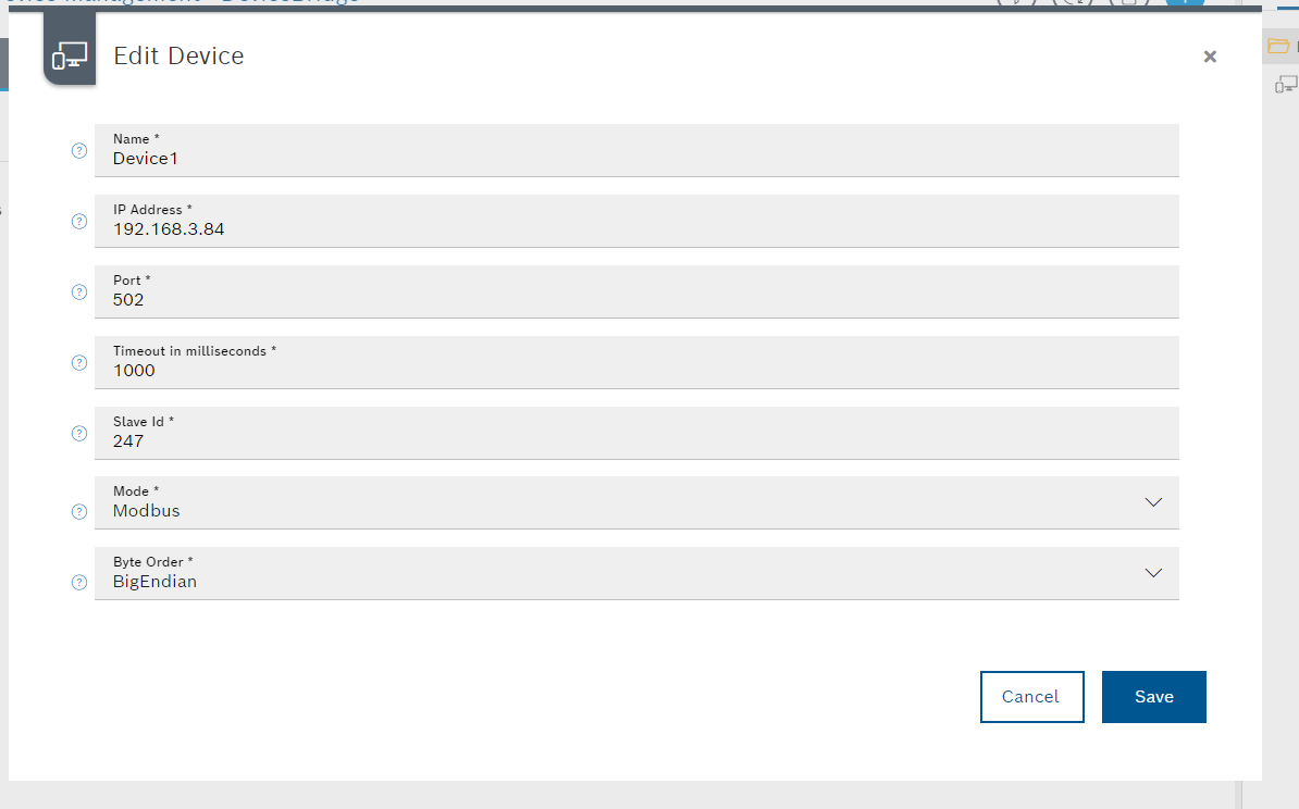
Here are the images for the important parameters.
Tasks with FC23 and FC16 are Configured.
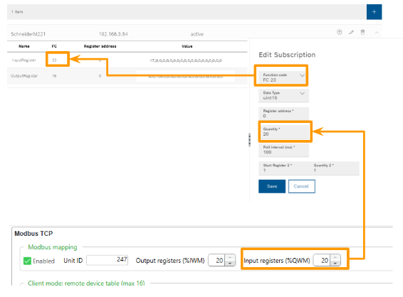
Input Register
Here is the configuration of the Input Register Task.
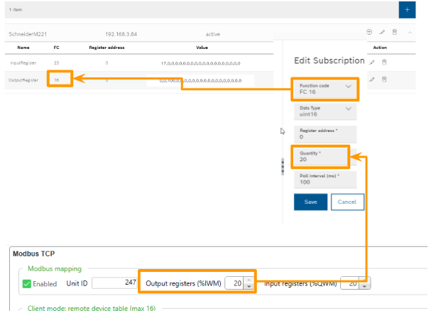
Output Register
Here is the configuration of the Output Register Task.
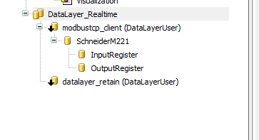
Configure DataLayer
Configure the DataLayer_Realtime to access the variables from ModbusTCP Apps.

Done!
Programming
Data Unit Type
DUT_ATV320_ModbusStatus_w0_structure
Here is the Data unit type of Modbus TCP Input Register 0 of Schneider CPU.
| TYPE DUT_ATV320_ModbusStatus_w0_structure : STRUCT RUN :BOOL; SL1_STOP :BOOL; SL1_ReqInited :BOOL; SL1_OP :BOOL; SL1_PARITALLYOP :BOOL; SL1_SUSPEND :BOOL; _b6,_b7,_b8,_b9 ,_b10,_b11,_b12 ,_b13,_b14,_b15 :BOOL; END_STRUCT END_TYPE |
uDUT_ATV320_ModbusStatus_w0
Here is the Union data type to group the WORD variables and the DUT_ATV320_ModbusStatus_w0_structure in the same memory offset.
| TYPE uDUT_ATV320_ModbusStatus_w0 : UNION _raw :WORD; data :DUT_ATV320_ModbusStatus_w0_structure; END_UNION END_TYPE |
DUT_ATV320_ModbusStatus_w1_structure
Here is the Data unit type of Modbus TCP Input Register 1 of Schneider CPU.
| TYPE DUT_ATV320_ModbusStatus_w1_structure : STRUCT IO1_Drive_Power_IL :BOOL; IO1_OP_IL :BOOL; _b2,_b3,_b4,_b5 ,_b6,_b7,_b8,_b9 ,_b10,_b11,_b12 ,_b13,_b14,_b15 :BOOL; END_STRUCT END_TYPE |
uDUT_ATV320_ModbusStatus_w1
Here is the Union data type to group the WORD variables and the DUT_ATV320_ModbusStatus_w1_structure in the same memory offset.
| TYPE uDUT_ATV320_ModbusStatus_w1 : UNION _raw :WORD; data :DUT_ATV320_ModbusStatus_w1_structure; END_UNION END_TYPE |
DUT_ATV320_ModbusStatus_w2_Structure
Here is the Data unit type of Modbus TCP Input Register 2 of Schneider CPU.
| TYPE DUT_ATV320_ModbusStatus_w2_Structure : STRUCT IO1_MC_POwer_Status :BOOL; IO1_MC_Power_Error :BOOL; IO1_MC_JOG_FW :BOOL; IO1_MC_JOG_BW :BOOL; IO1_MC_JOG_DONE :BOOL; IO1_MC_JOG_BUSY :BOOL; IO1_MC_JOG_CMDABORED :BOOL; IO1_MC_JOG_ERROR :BOOL; IO1_MC_MOVEVEL_IL :BOOL; IO1_MC_MOVEVEL_CMD :BOOL; IO1_MC_MOVEVEL_CONTUPDATE :BOOL; IO1_MC_MOVEVEL_INVEL :BOOL; IO1_MC_MOVEVEL_BUSY :BOOL; IO1_MC_MOVEVEL_CMDABORED :BOOL; IO1_MC_MOVEVEL_ERROR :BOOL; IO1_STATUS_VALID :BOOL; END_STRUCT END_TYPE |
uDUT_ATV320_ModbusStatus_w2
Here is the Union data type to group the WORD variables and the DUT_ATV320_ModbusStatus_w2_structure in the same memory offset.
| TYPE uDUT_ATV320_ModbusStatus_w2 : UNION _raw :WORD; data :DUT_ATV320_ModbusStatus_w2_structure; END_UNION END_TYPE |
DUT_ATV320_ModbusStatus_w3_Structure
Here is the Data unit type of Modbus TCP Input Register 3 of Schneider CPU.
| TYPE DUT_ATV320_ModbusStatus_w3_Structure : STRUCT IO1_STATUS_ERRORSTOP :BOOL; IO1_STATUS_DISABLED :BOOL; IO1_STATUS_STOPPING :BOOL; IO1_STATUS_STANDSTILL :BOOL; IO1_STATUS_CONTMOTION :BOOL; IO1_STATUS_ERROR :BOOL; IO1_MCREADMOTIONSTS_VALID :BOOL; IO1_MCREADMOTIONSTS_CONSTANTVEL :BOOL; IO1_MCREADMOTIONSTS_ACCELERATING :BOOL; IO1_MCREADMOTIONSTS_DECELERATING :BOOL; IO1_MCREADMOTIONSTS_ERROR :BOOL; IO1_MC_RESET_DONE :BOOL; IO1_MC_RESET_BUSY :BOOL; IO1_MC_RESET_ERROR :BOOL; IO1_MC_STOP_DONE :BOOL; IO1_MC_STOP_BUSY :BOOL; END_STRUCT END_TYPE |
uDUT_ATV320_ModbusStatus_w3
Here is the Union data type to group the WORD variables and the DUT_ATV320_ModbusStatus_w3_structure in the same memory offset.
| TYPE uDUT_ATV320_ModbusStatus_w3 : UNION _raw :WORD; data :DUT_ATV320_ModbusStatus_w3_structure; END_UNION END_TYPE |
DUT_ATV320_ModbusStatus_w4_Structure
Here is the Data unit type of Modbus TCP Input Register 4 of Schneider CPU.
| TYPE DUT_ATV320_ModbusStatus_w4_Structure : STRUCT IO1_MC_STOP_ERROR :BOOL; _b1,_b2,_b3,_b4,_b5 ,_b6,_b7,_b8,_b9 ,_b10,_b11,_b12 ,_b13,_b14,_b15 :BOOL; END_STRUCT END_TYPE |
uDUT_ATV320_ModbusStatus_w4
Here is the Union data type to group the WORD variables and the DUT_ATV320_ModbusStatus_w4_structure in the same memory offset.
| TYPE uDUT_ATV320_ModbusStatus_w4 : UNION _raw :WORD; data :DUT_ATV320_ModbusStatus_w4_structure; END_UNION END_TYPE |
DUT_ATV320_ModbusStatus
Here is the Data type that groups all Status Word into one Data Type again – we will define a variable with this type in GVL again.
| TYPE DUT_ATV320_ModbusStatus : STRUCT w0 :uDUT_ATV320_ModbusStatus_w0; w1 :uDUT_ATV320_ModbusStatus_w1; w2 :uDUT_ATV320_ModbusStatus_w2; w3 :uDUT_ATV320_ModbusStatus_w3; w4 :uDUT_ATV320_ModbusStatus_w4; w5_ActualSpeed :INT; END_STRUCT END_TYPE |
DUT_ATV320_ModbusCmds_w0_structure
Here is the Data unit type of Modbus TCP Output Register 0 of Schneider CPU.
| TYPE DUT_ATV320_ModbusCmds_w0_structure : STRUCT PowerON :BOOL; JogFW :BOOL; JogBW :BOOL; MoveVel :BOOL; ContUpdate :BOOL; Reset :BOOL; Stop :BOOL; _b7,_b8,_b9 ,_b10,_b11,_b12 ,_b13,_b14,_b15 :BOOL; END_STRUCT END_TYPE |
uDUT_ATV320_ModbusCmds_w0
Here is the Union data type to group the WORD variables and the DUT_ATV320_ModbusCmds_w0_structure in the same memory offset.
| TYPE uDUT_ATV320_ModbusCmds_w0 : UNION _raw :WORD; data :DUT_ATV320_ModbusCmds_w0_structure; END_UNION END_TYPE |
DUT_ATV320_ModbusCmds
Here is the Data type that groups all Command Words into one Data Type again – we will define a variable with this type in GVL again.
| TYPE DUT_ATV320_ModbusCmds : STRUCT w0 :uDUT_ATV320_ModbusCmds_w0; w1 :WORD; w2_Jog_Cmd :INT; w3_MoveVel :INT; END_STRUCT END_TYPE |
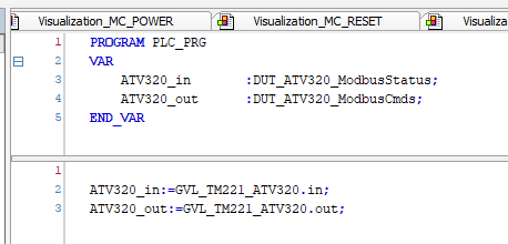
Pous
We need to use these variables inside the program or configure the update method,
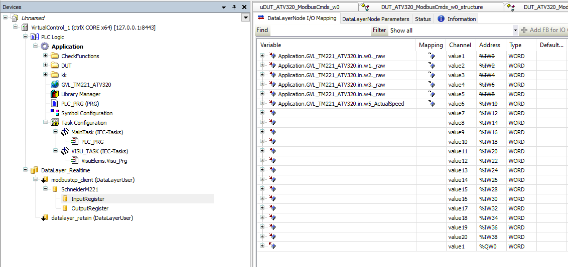
Mapping
Do not forget to map all Variables between DataLayer_Realtime and user program.

HMI
Now is the time to create our web Visualization.
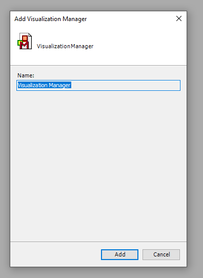
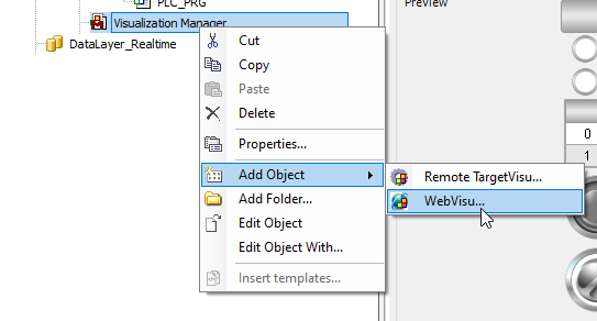
Add Visualization Manager
Click your Application>Right Click>Add Object>Visualization Manager.
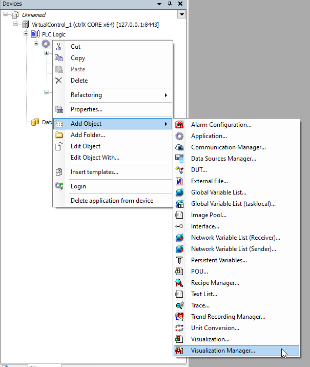
Press Add to continue.
Visuilation
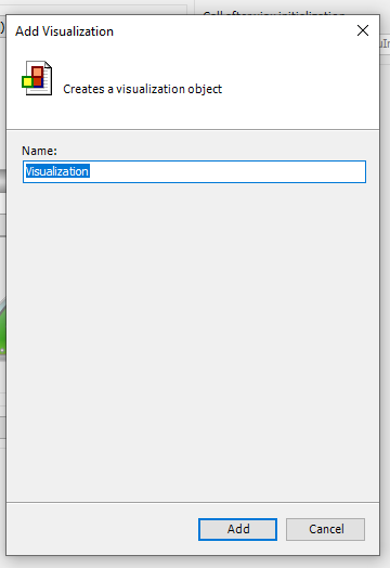
Select your Application again>Right Click>Add Object>Visualization.
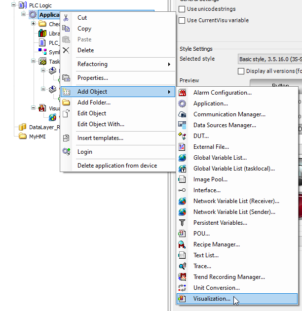
Enter your Visualization Screen name>Add.
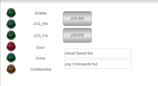
Visualization_MC_JOG
Here is the Screen for the Jog Operation.
Visualization_MC_POWER
Here is the Screen for the ATV320 Power ON/OFF Operation.

Visualization_MC_RESET
Here is the Screen for the ATV320 Reset Operation.

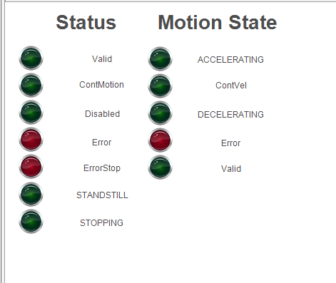
Visualization_MC_Status
Here is the Screen for the Status/Motion State of ATV320.
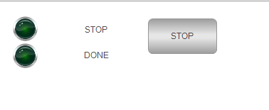
Visualization_MC_STOP
Here is the Screen for the ATV320 Stop Operation.
Visualization_MC_VEL
Here is the Screen for the ATV320 Moving with Velocity Setpoint Operation.

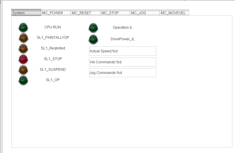
Visualization_System
Here is the Screen for the Schneider TM221 CPU status.
Visualization
Finally we will use the Tab elements to configure our operation screen.
Add WebVisu
Select the Visualization Manager>Add Object >WebVisu.
Enter the WebVisu Name.

Done!
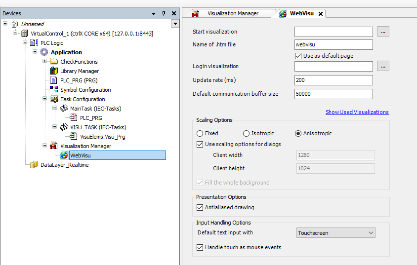
Press the … Button in the “Start visualization” field to setup your startup screen.

choose your screen and OK.

Access
Please use this link to access the webvisu.
http://localhost:8080/webvisu.htm
Result
Source Project
Please access this link to download the source project and you can find the Ctrlx Project and Schneider Project inside