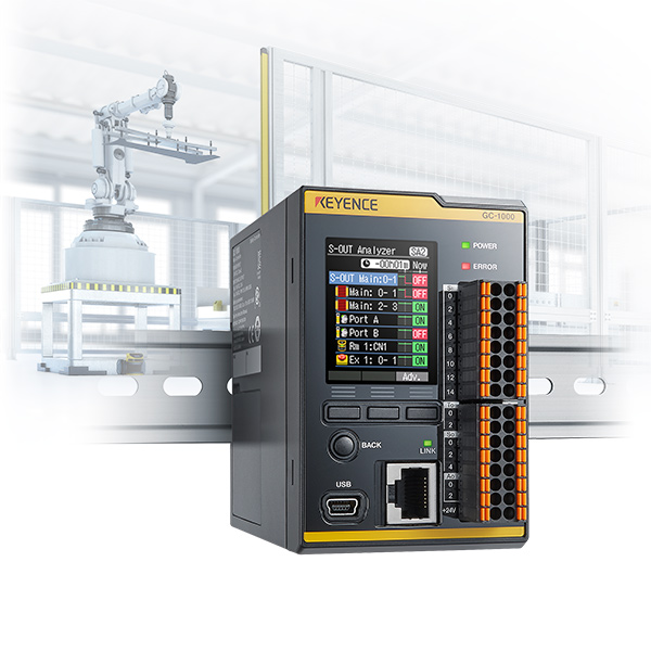
This is the second episode of a new article about the Safety Controller GC-1000 from Keyence. This time we will create a project from scratch and create a simple safety program with emergency stops and lamps connected.
Let’s get started!
Reference Link
Response Time
The response time of the GC hardware, is the maximum time required for the GC series to execute the programme based on the signal from the safety input device and to shut down the output sent to the safety output device. The safety distance (minimum distance) is calculated using the response time.
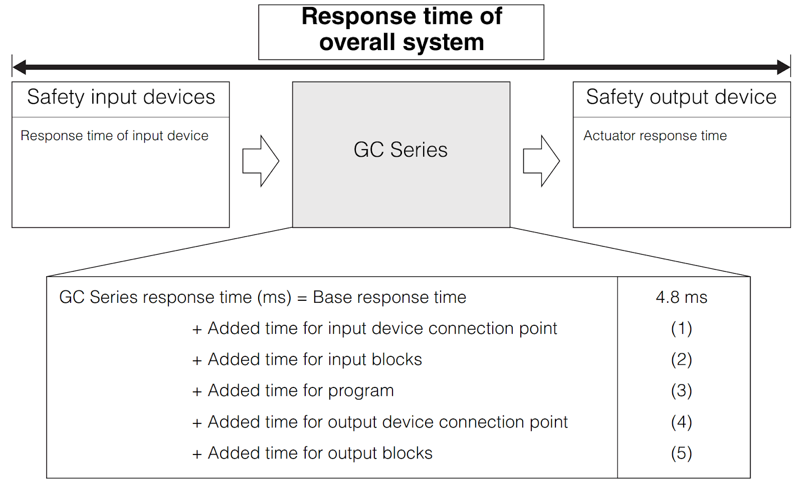
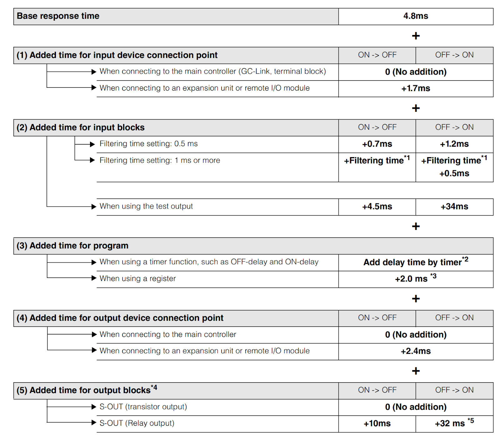
Here are the internal details of response times.
Implementation
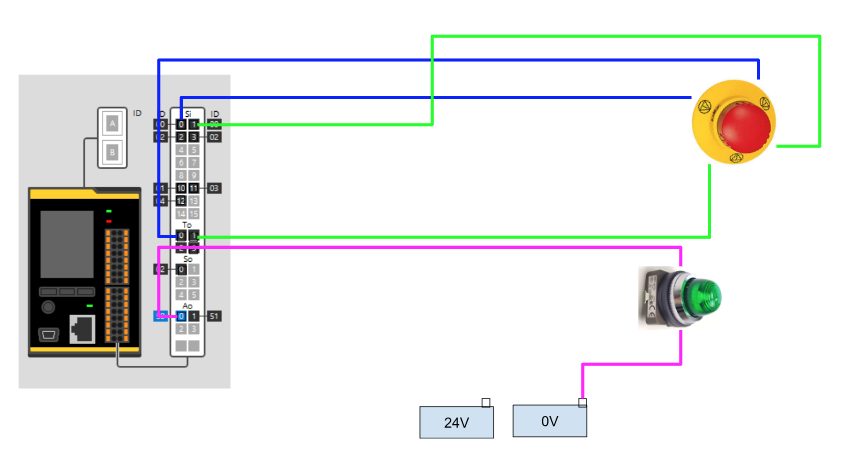
This is the wiring for this article. The emergency stop is connected to the input of the GC-1000 and the Test Input, while the AXU-OUT is connected to the lamp in a simple configuration.
New Project
Now create a new project from GC-Configurator.
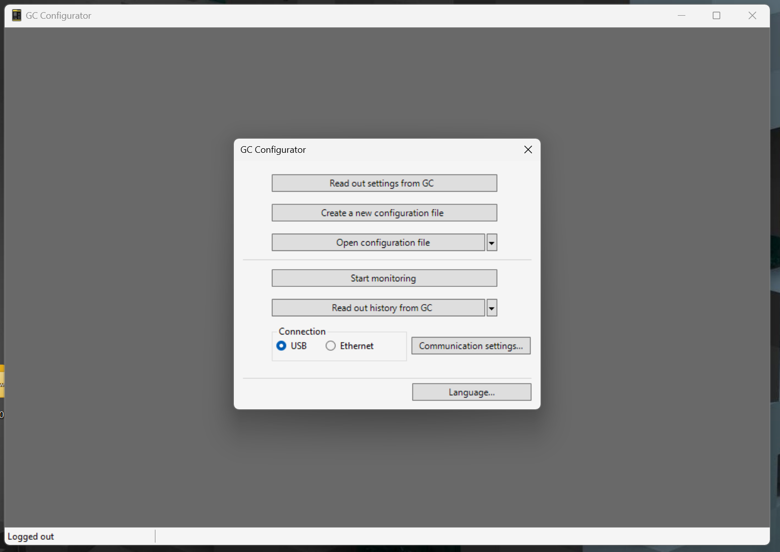
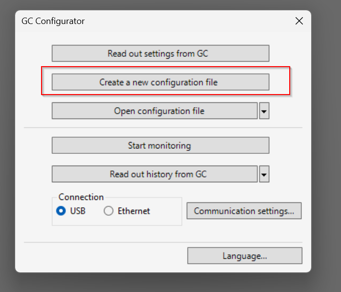
Click Create a new configuration file.
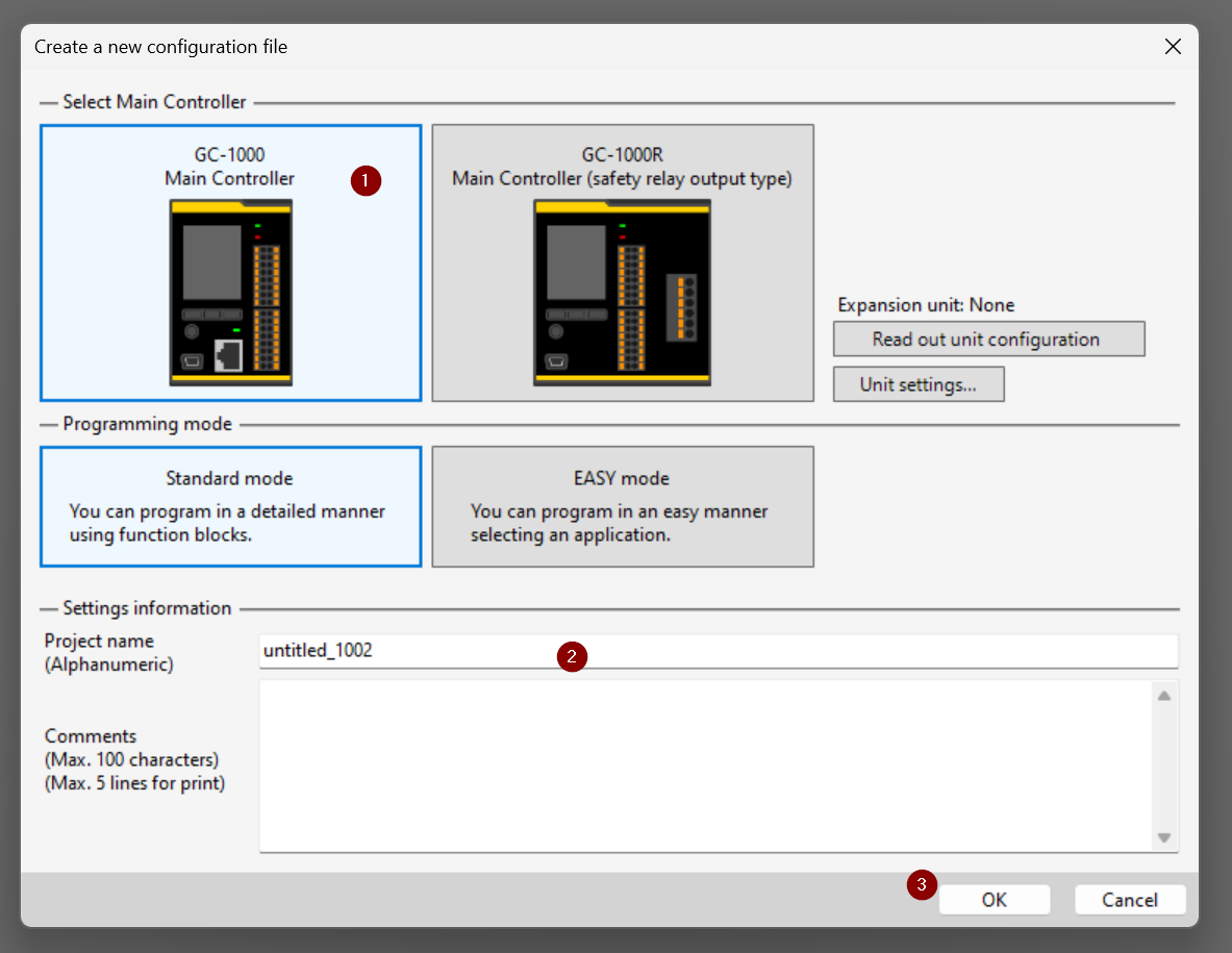
Select GC-1000>Standard Mode and OK to create a new one.
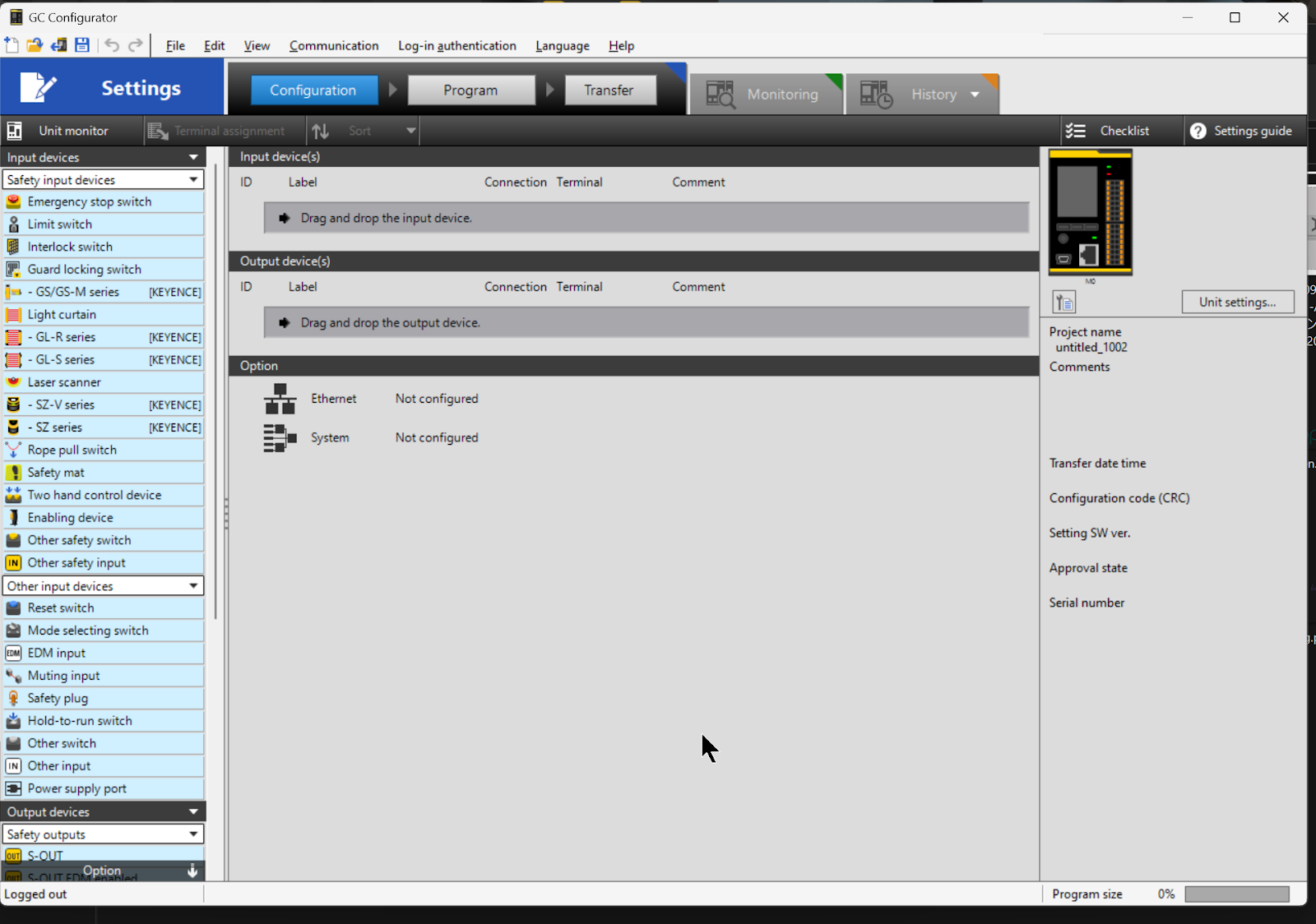
Done!A new project has been created.
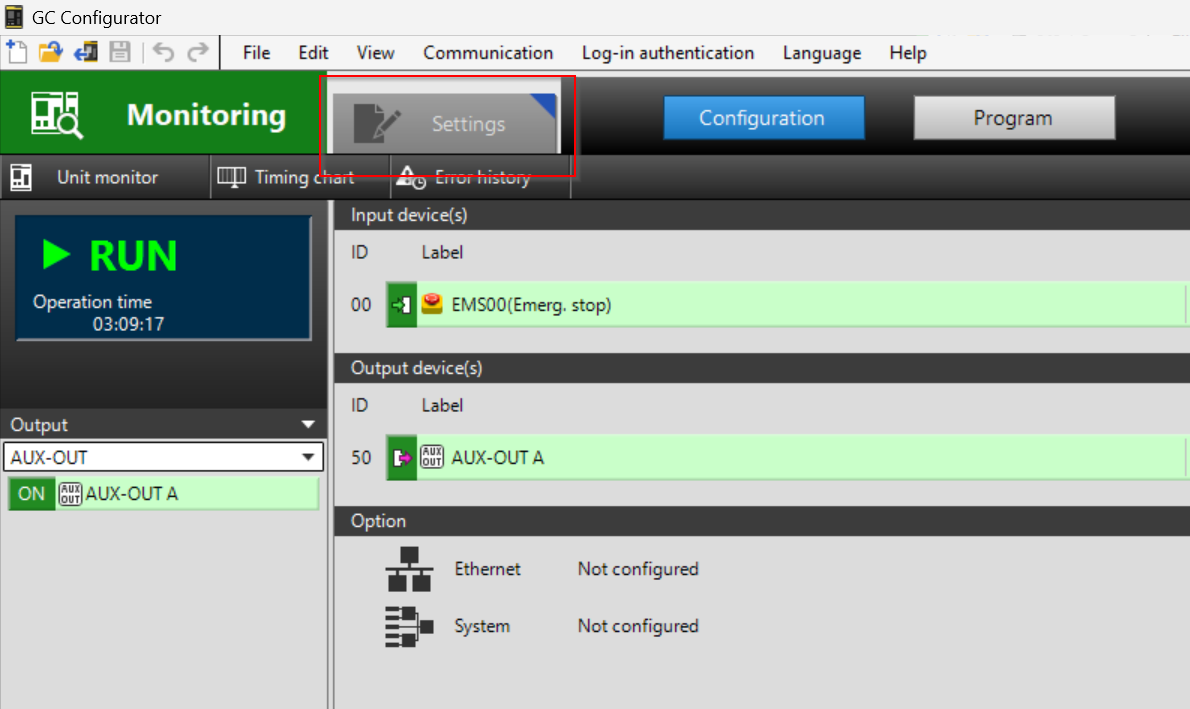
Configure INPUT
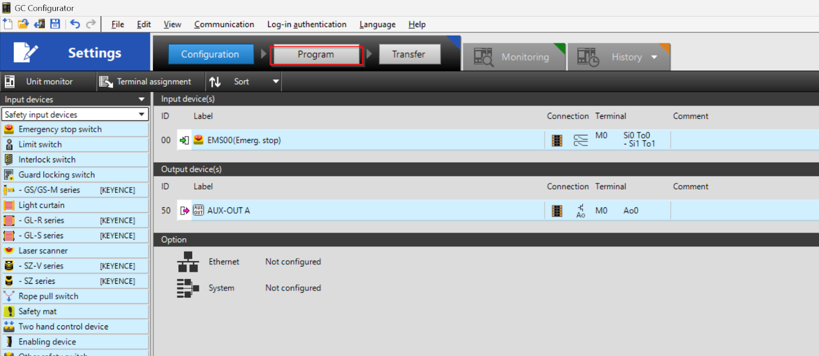
This time, we will connect the GC-1000 to the emergency stop, so let’s drop the Emergency stop switch from Input devices to Input device(s).
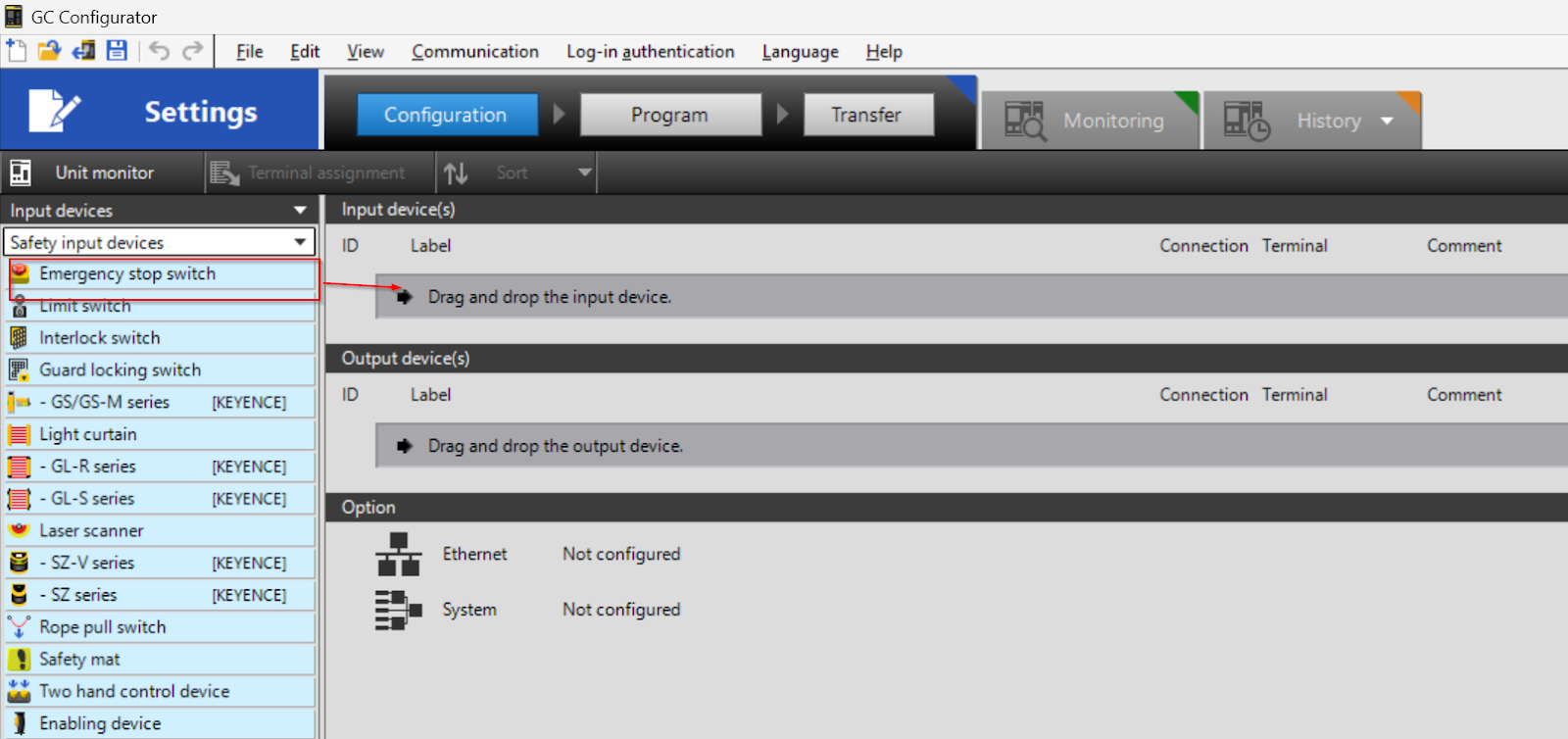
The operation is shown in the diagram below.
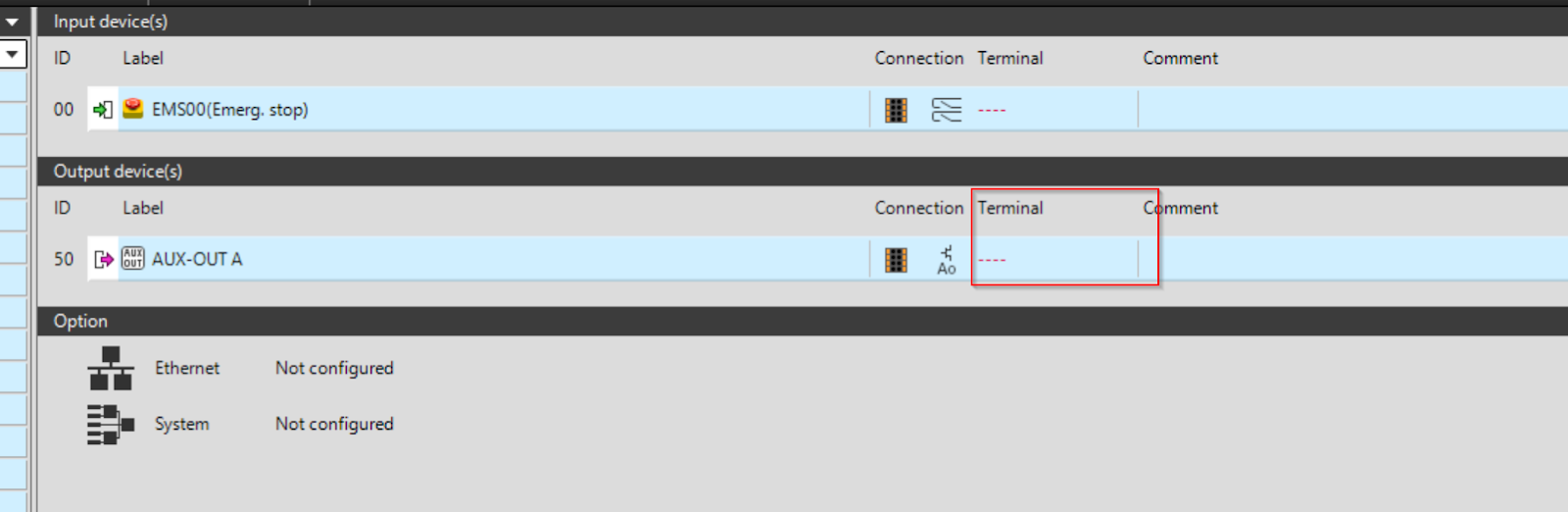
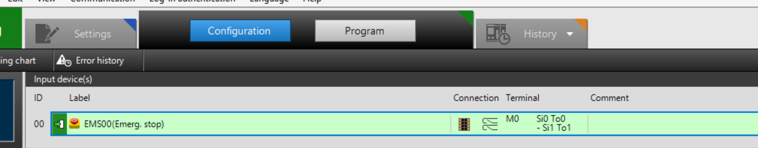
Done!An emergency stop has been added to Input device(s) ID00.
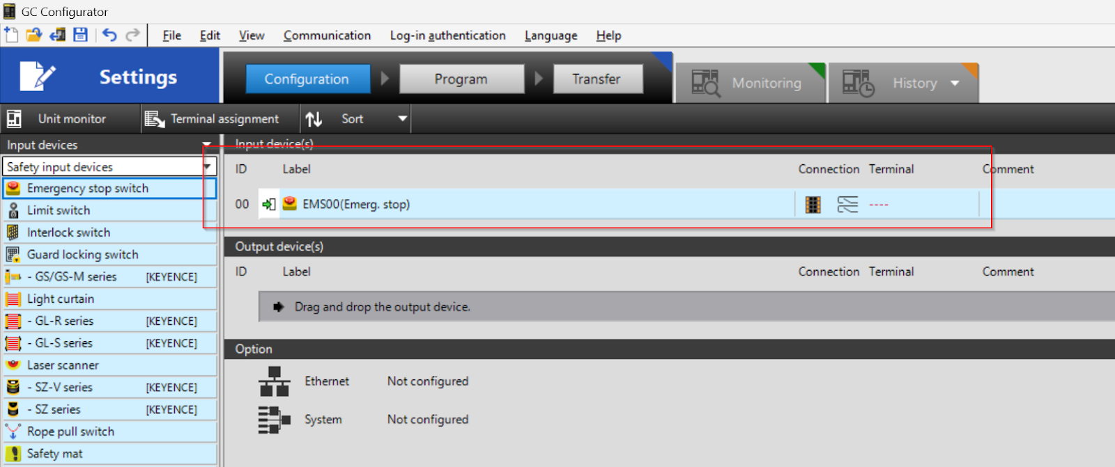
Click on Terminal to set the terminal block to be connected with an emergency stop.
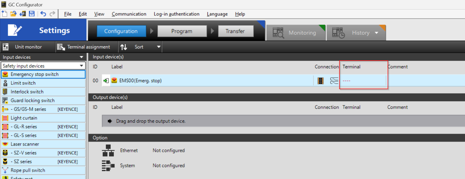
The Select Unit screen is displayed.
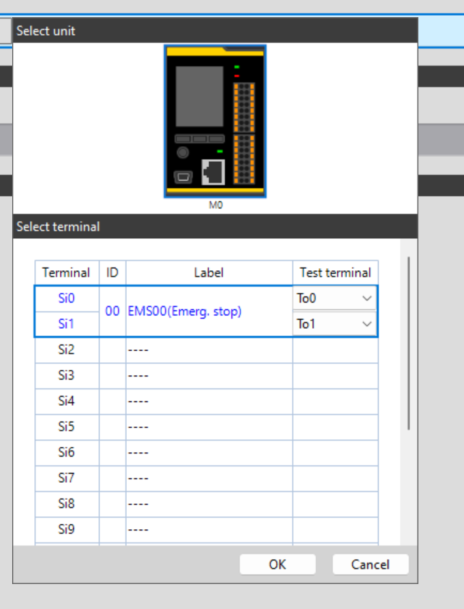
As shown in the diagram below, it is possible to change the Terminal for the emergency stop connection and confirm with Ok when you have finished setting it up.
Done!Terminal configuration is also complete.
Configure AUX OUTPUT
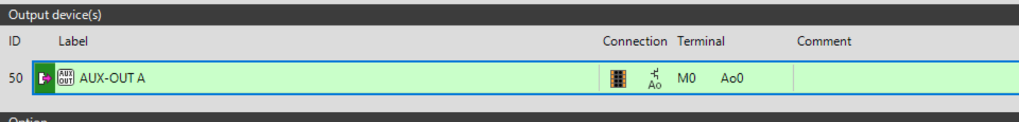
Next, to add the AUX OUT to the project, drop Other output>AUX-OUT into the Output device(s).
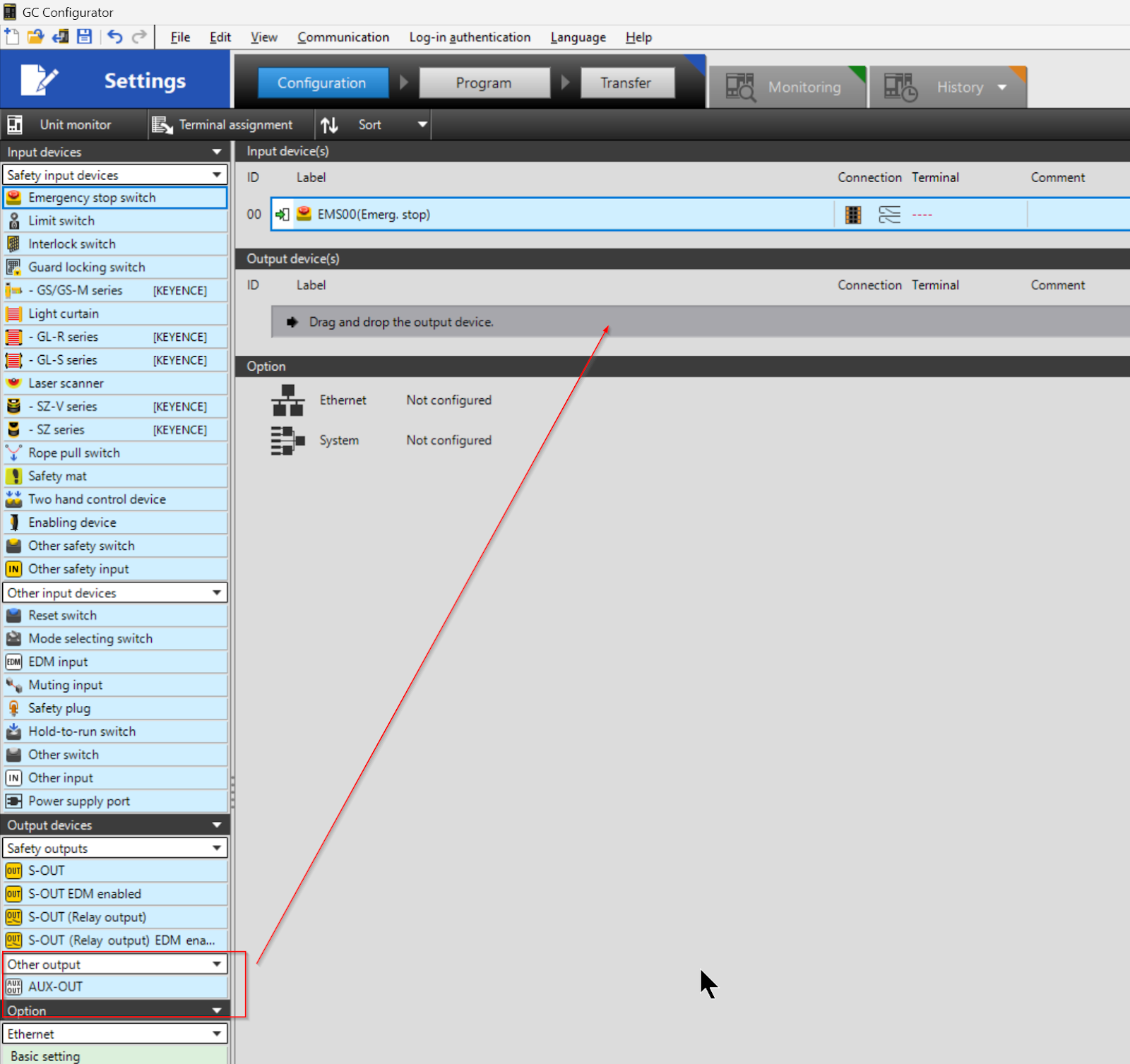
The operation is shown in the diagram below.
Next, click on Terminal to set the terminal block to which AUX-OUT A is connected.
The Select Unit screen is displayed.
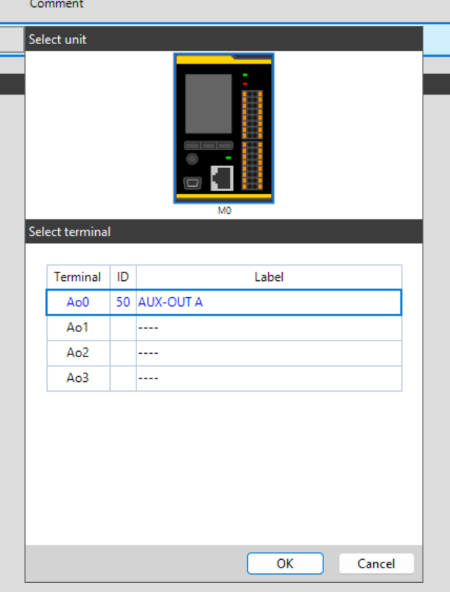
The terminal block connected to AUX-OUT can be changed as shown in the diagram below, and the setting is confirmed with Ok button.

Done!
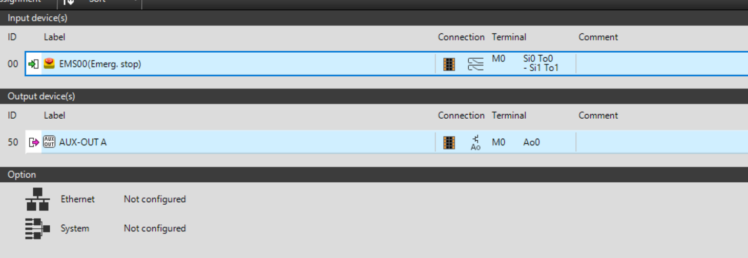
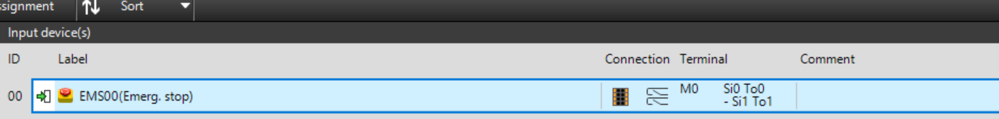
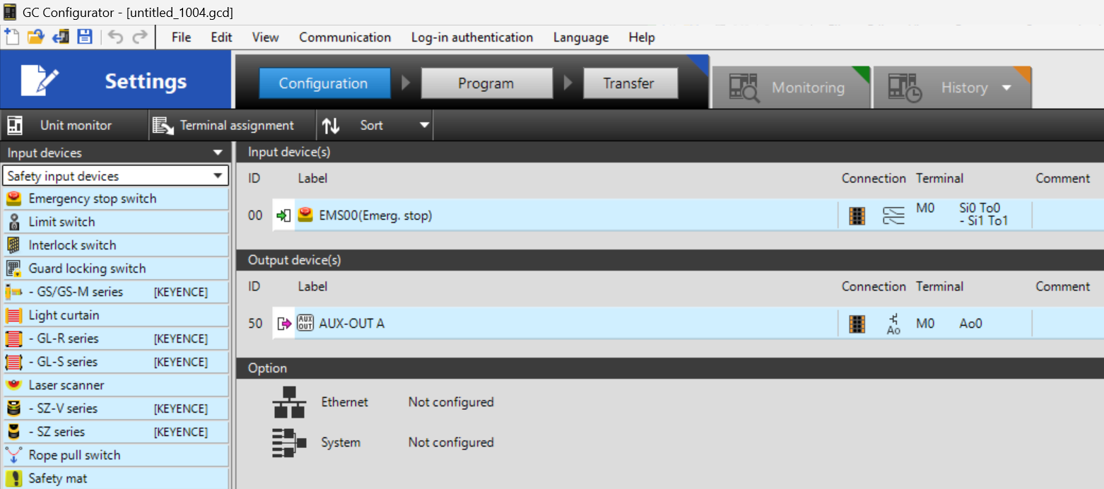
Check Wiring
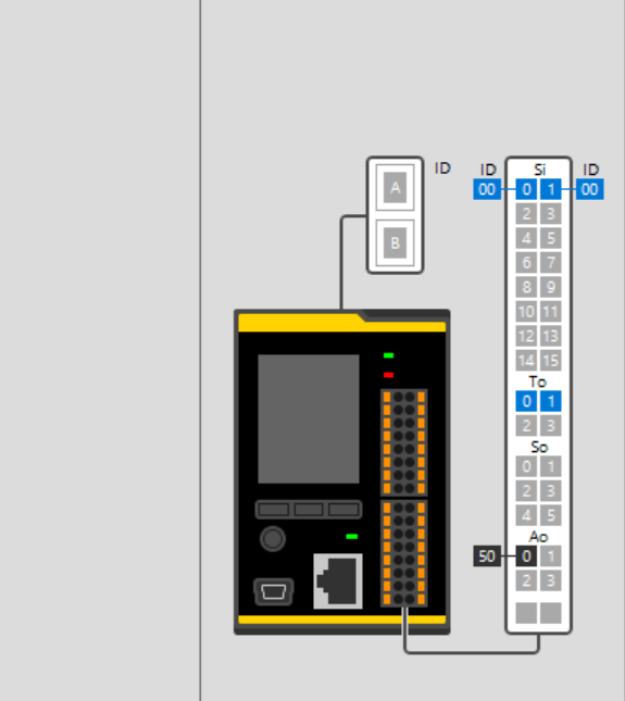
You can check the wiring of each terminal block from the GC-Configurator. for example, Select the emergency stop ID 00 that has just been added.
The wiring method for that ID00/ID01 is displayed in the bottom right-hand corner.
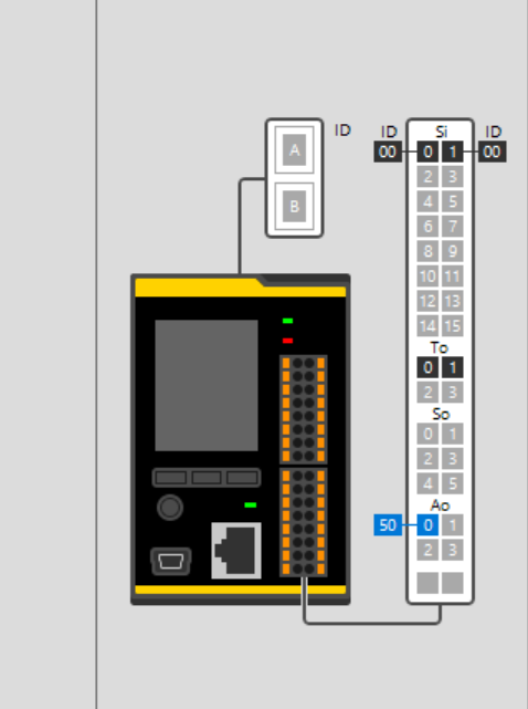
Also, click on AUX-OUT to see the wiring diagram.
The wiring instructions for that Ao50 are shown in the bottom right-hand corner.
Program
From now on, click on Program to create a simple safety program.
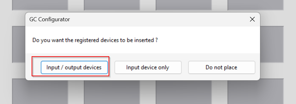
The Create Safety Program screen appears and a popup appears asking if you want to register the inputs and outputs defined in the Configuration screen earlier in the programme. PopUP will appear.
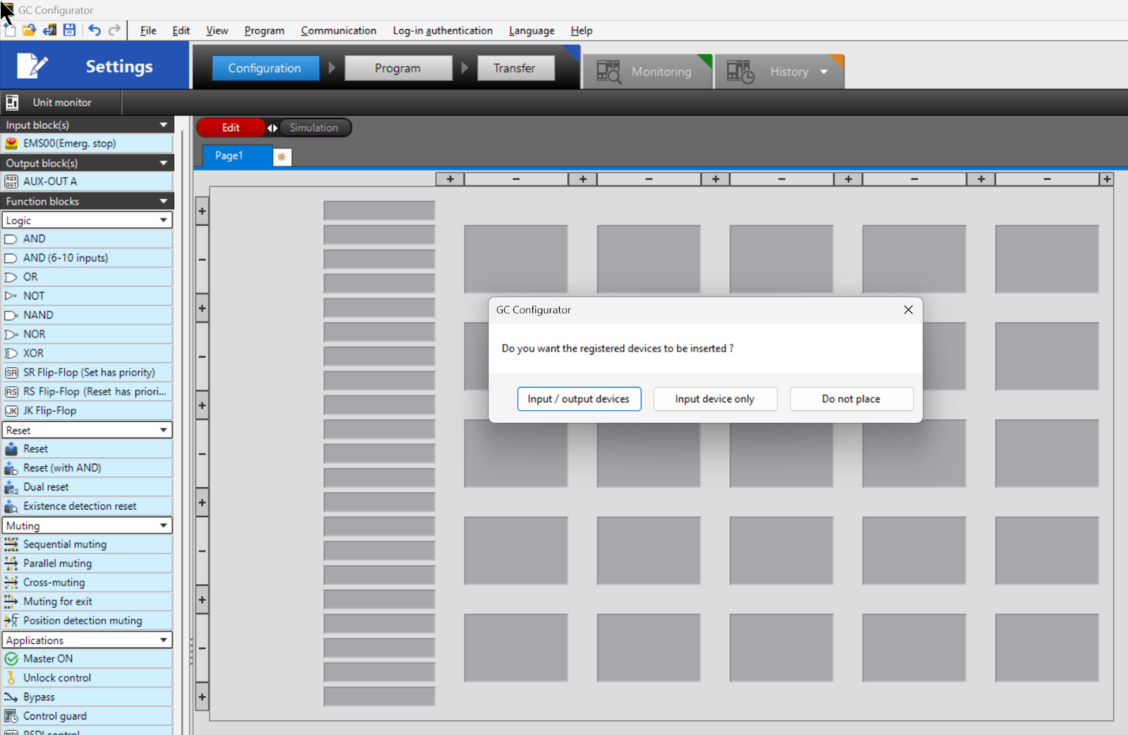
Click on “Input/output device”.
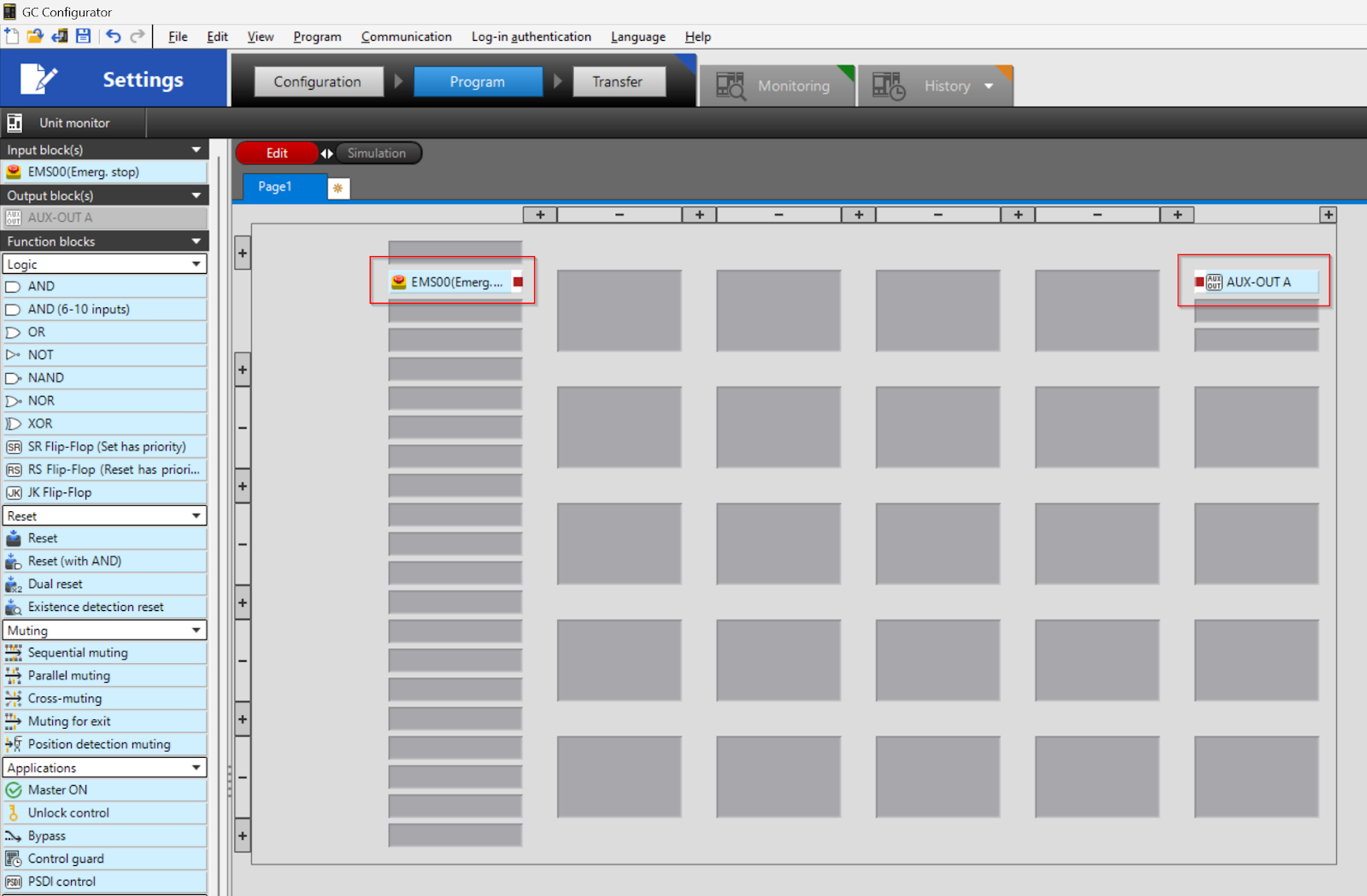
The emergency stop input and the output of AUX-OUT A are automatically registered in the programme.
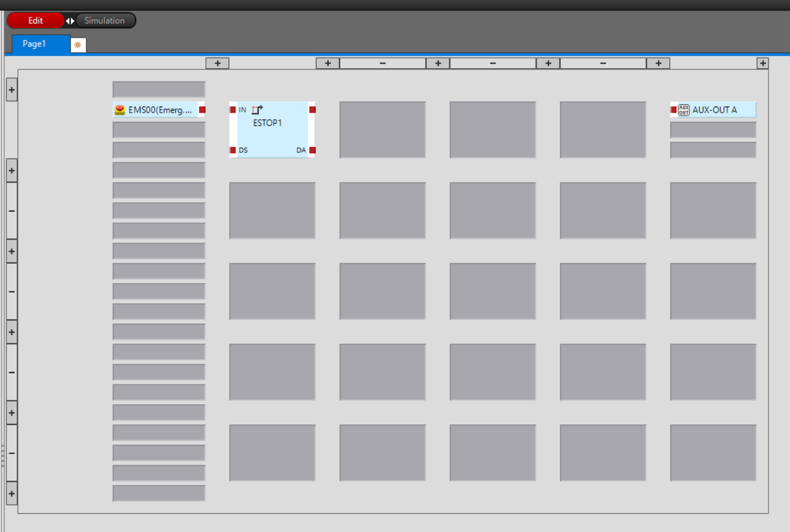
Add Delay
Add On-Delay from Timers/Counters.
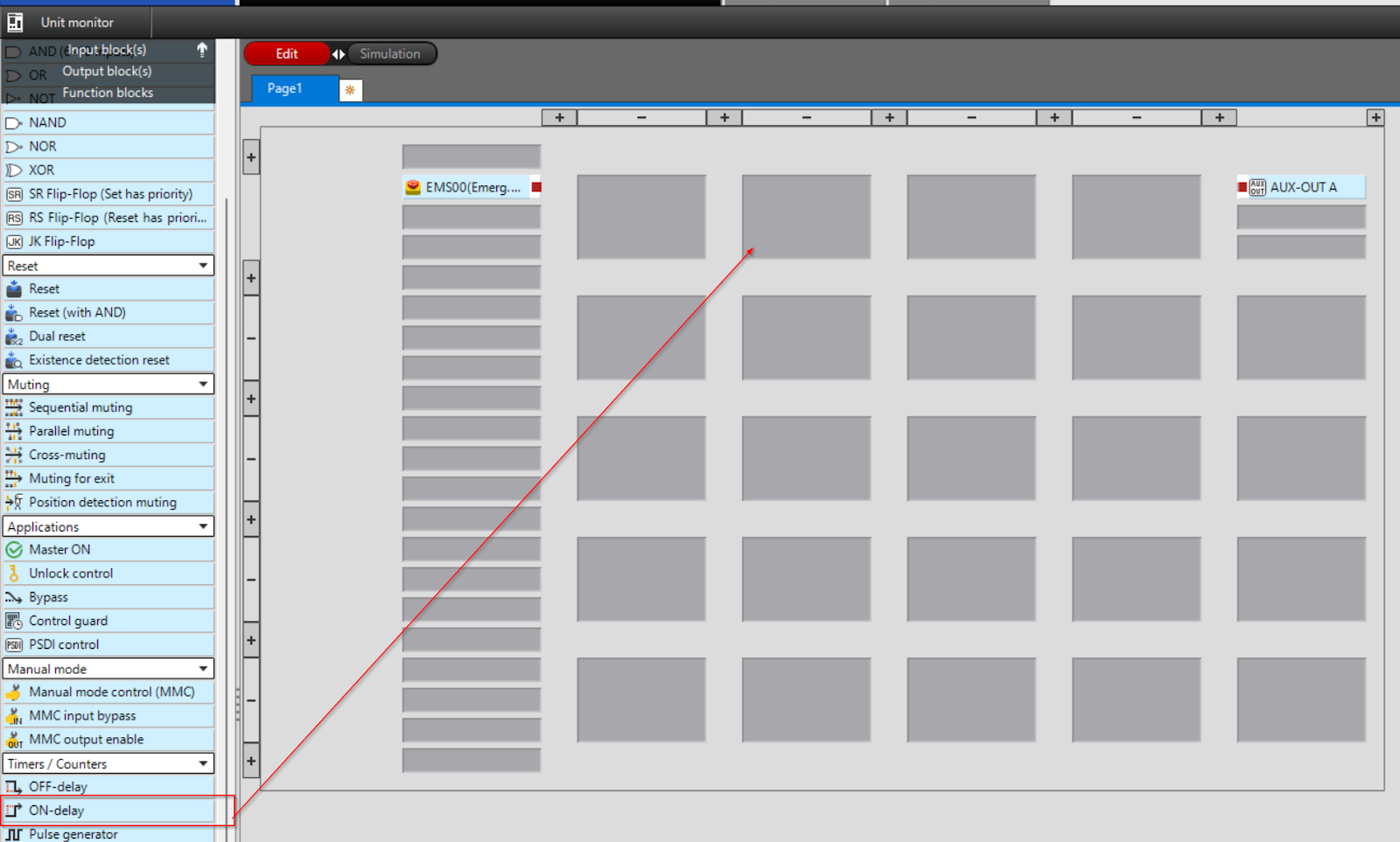
You can add a Block simply by dropping it using the operation shown in the diagram below.
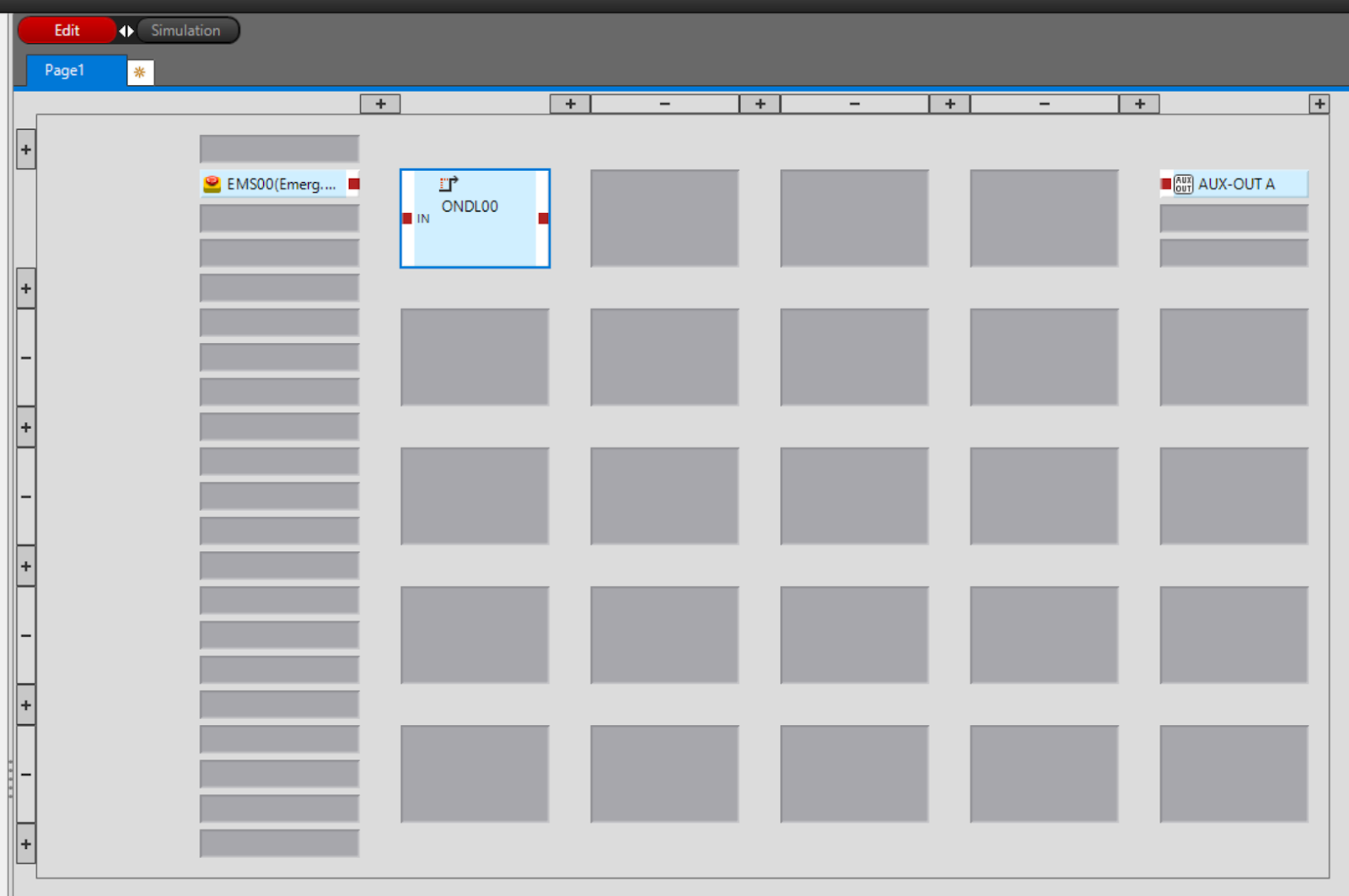
Done!Timer is added.
Configure
Double-click Timer to change the internal settings.
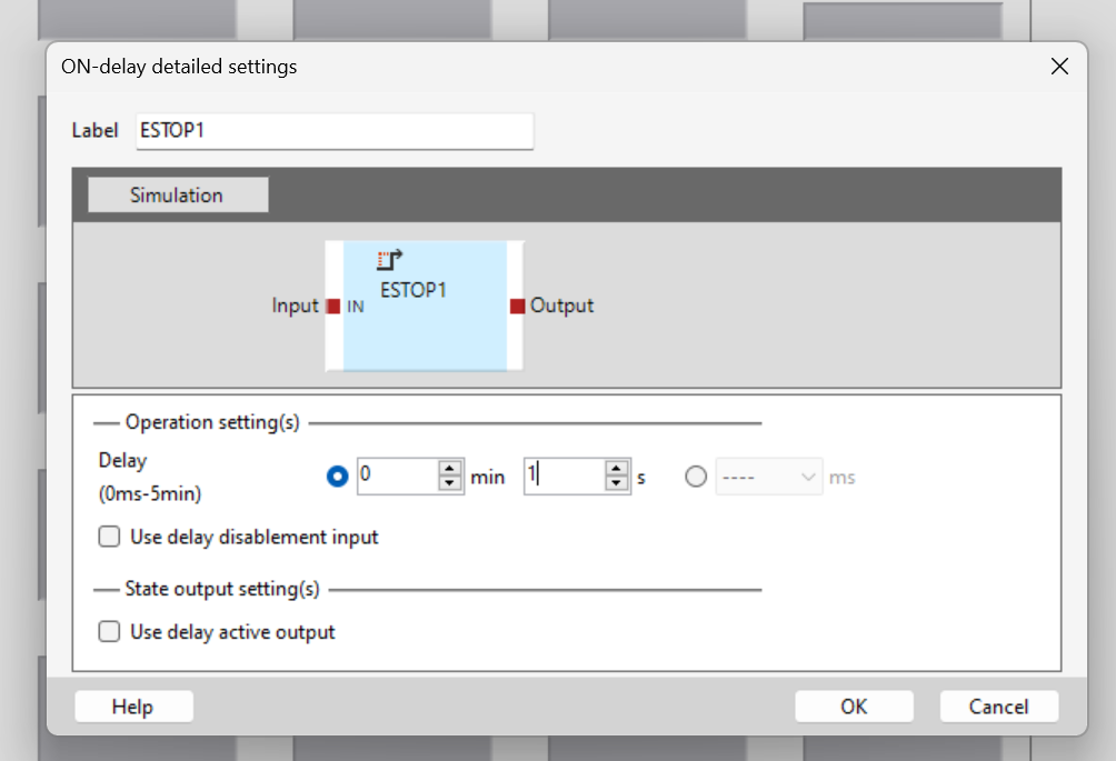
The Timer settings screen appears.
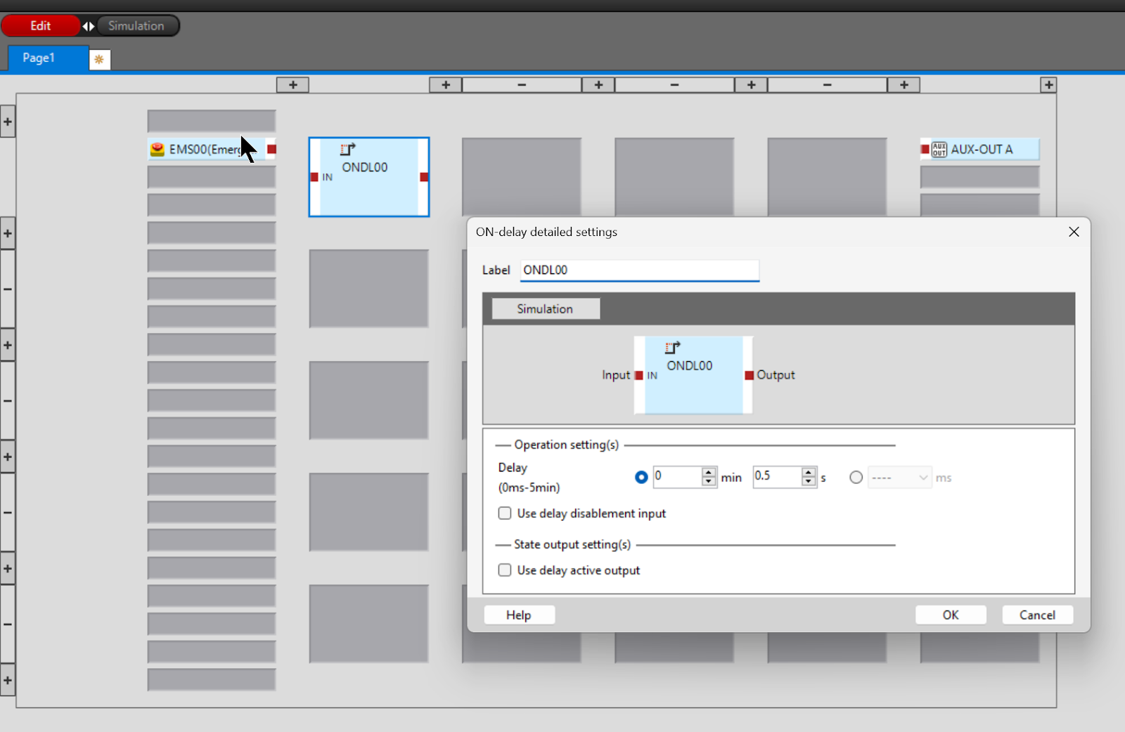
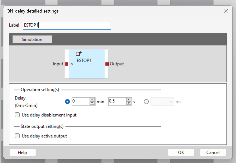
Label
The Label is actually the name under which the Block will appear on the Editor.
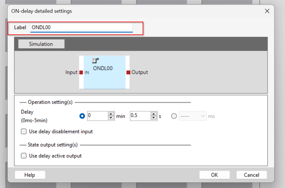
In this case, the name “ESTOP1” is used for clarity.
Delay
The Delay Field allows you to set the delay time for the Timer.
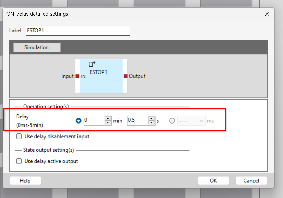
Set it to 1s this time.
Use delay disable input
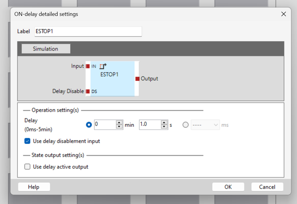
The Timer delay function can also be disabled by turning the Option here ON/OFF.
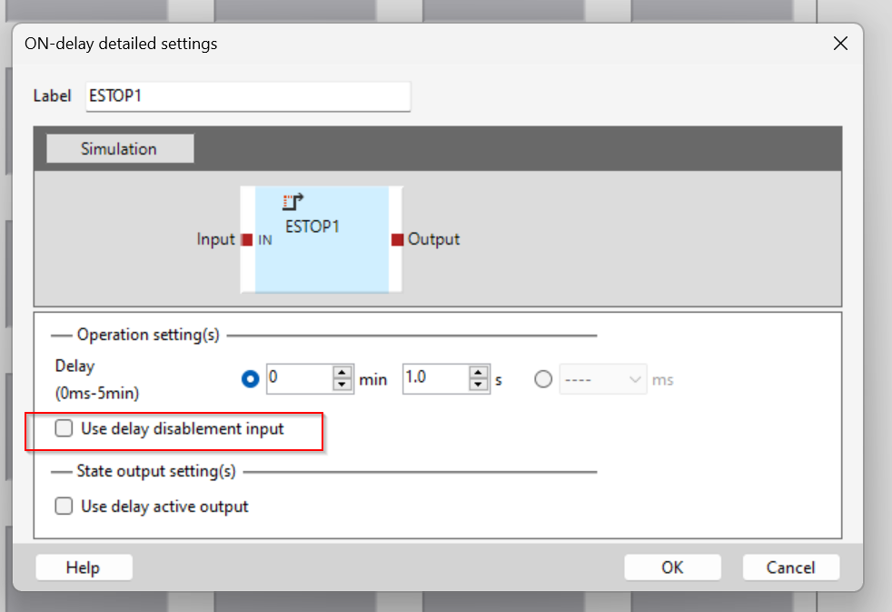
When the CheckBox is inserted, the input parameter “DS” is displayed, and if DS=True, the timer delay function is disabled.
Use delay activate output
The Option here indicates whether the Timer delay function is currently enabled.
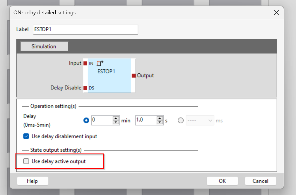
When the Checkbox is switched on, the output “DA” appears and True = the delay function is now active.
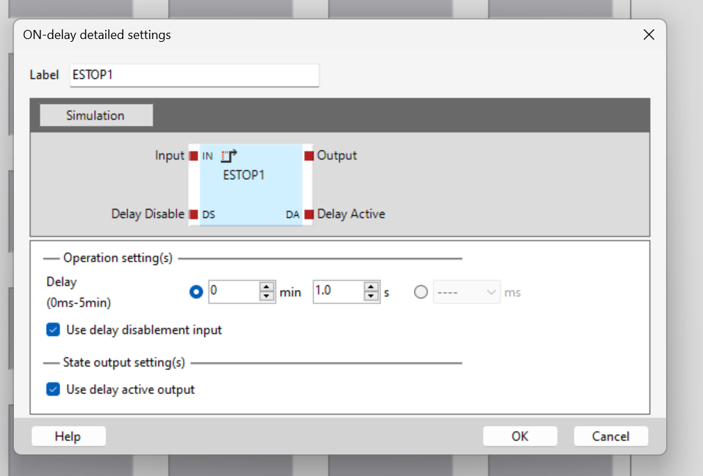
Done!We finished the setting.
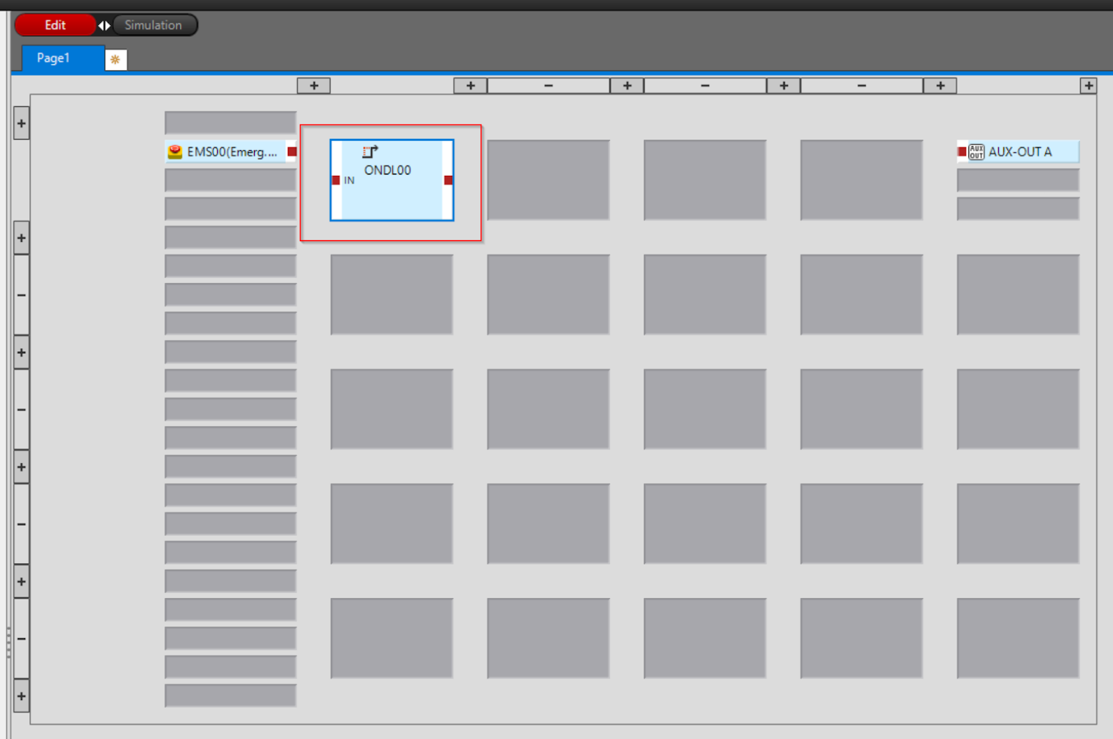
Adjust Position
The Block position can be moved within the program Editor.
The operation is shown in the diagram below.
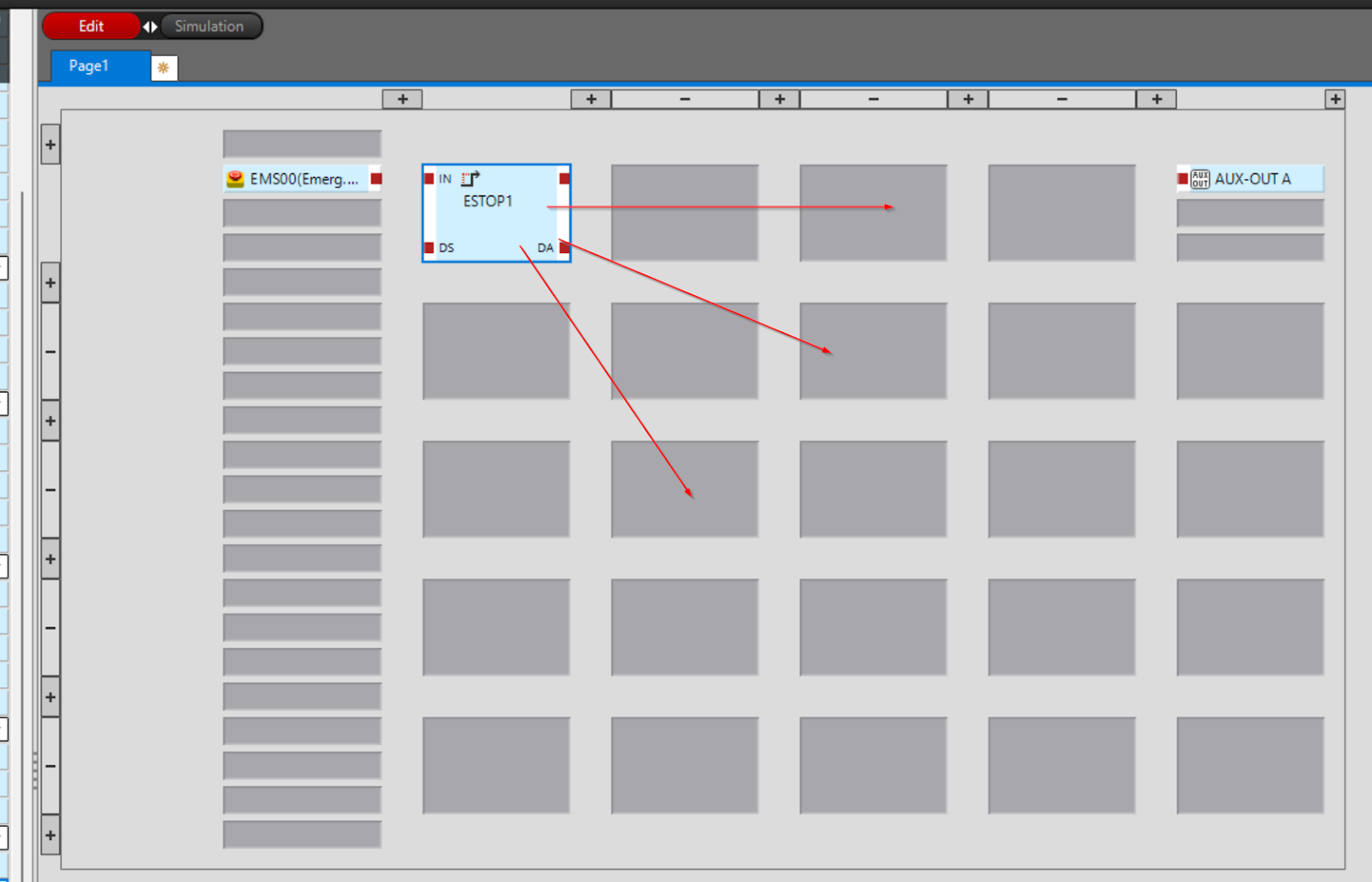
Connect IN
Now connect the emergency stop input directly to the Delay Timer IN that you have just added.
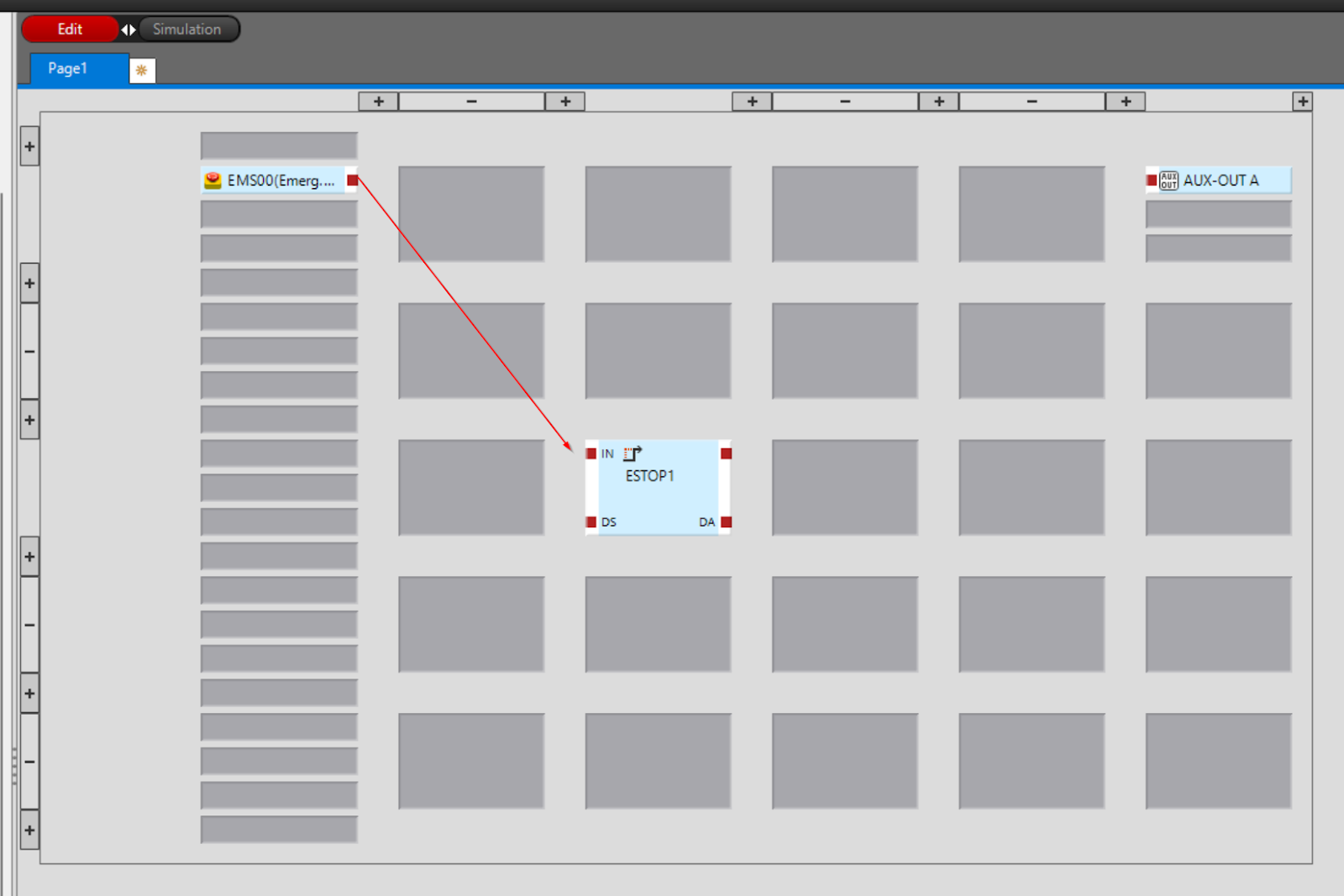
The operation is shown in the diagram below.
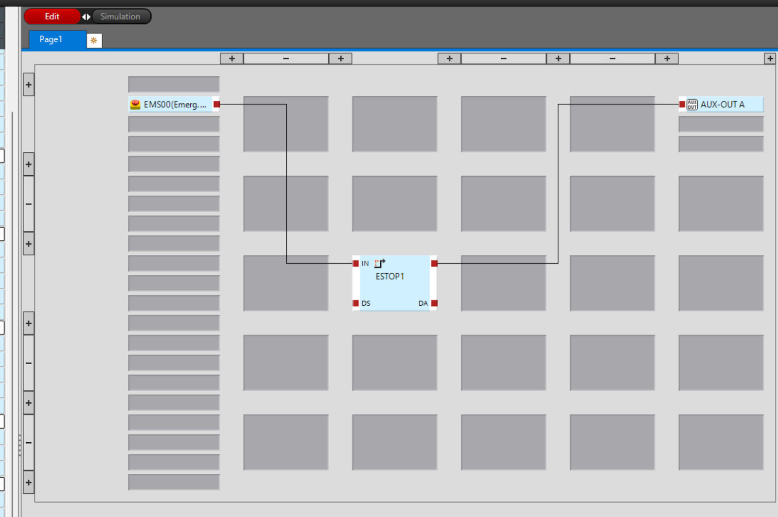
Connect OUT
Next, connect the output of the Delay Timer to AUX-OUT A.
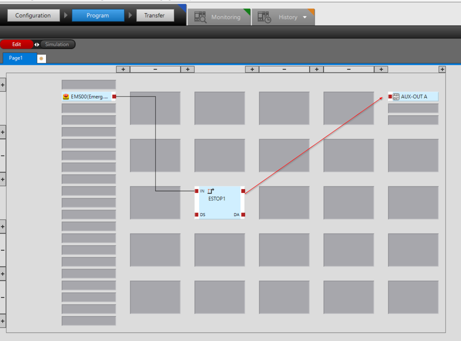
The operation is as shown in the figure below.
Finally
Done!
Simulation
Next to the Edit button, there is a Simulation button; click Simulation to switch the GC-Configurator to Simulation mode.
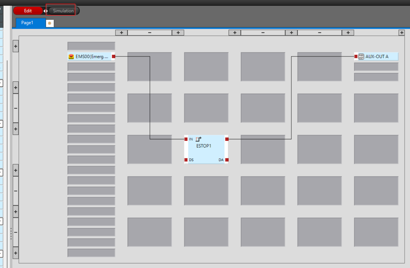
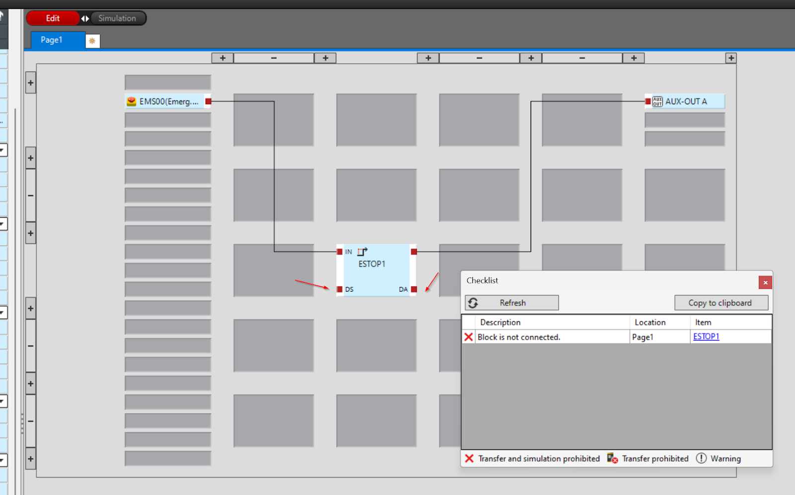
But there is an error in my program.
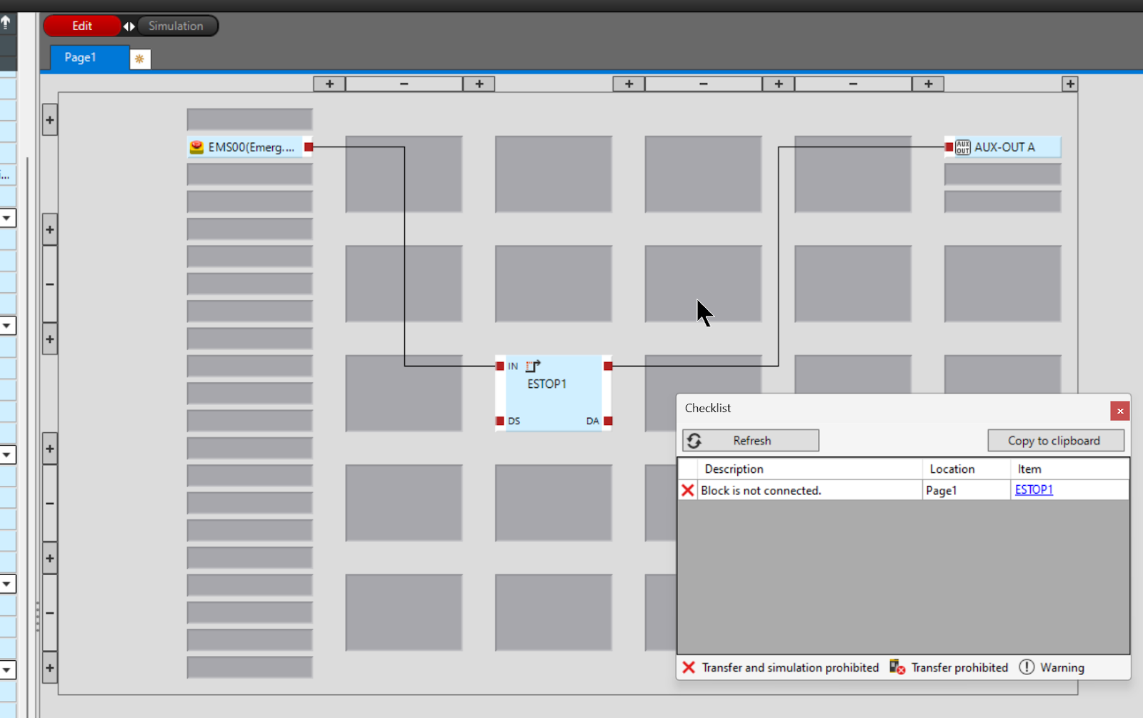
Turn off the DS/DA parameter settings in the Timer Block and switch to Simulation mode once more.
Done!This will allow you to switch Simulation.
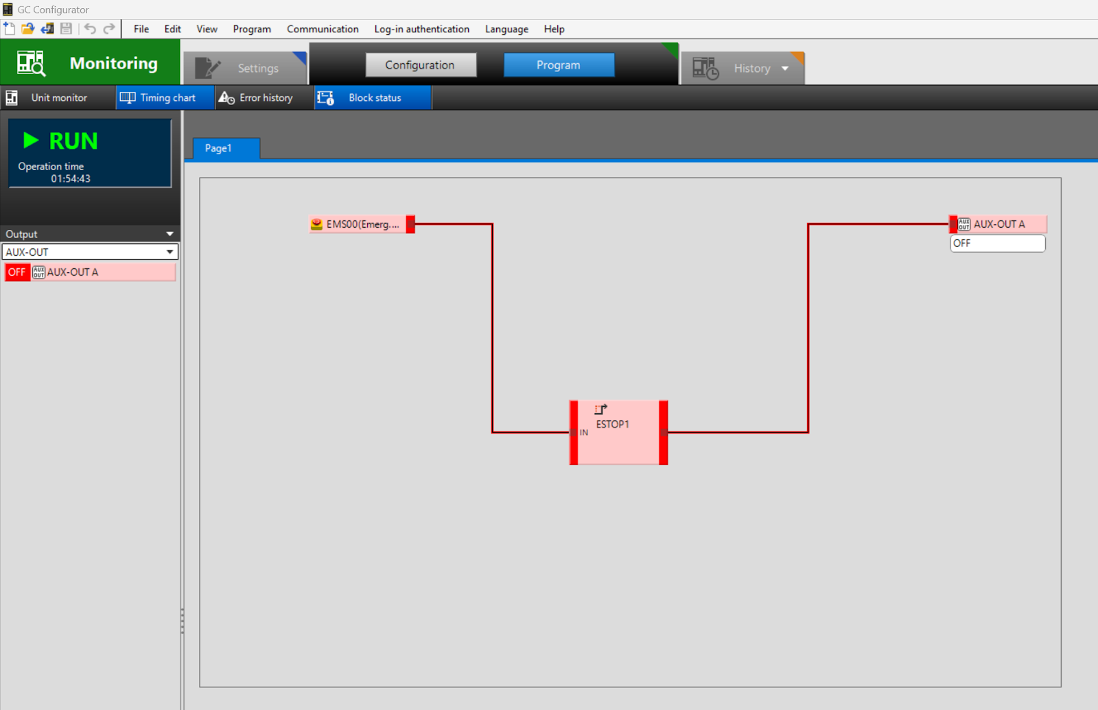
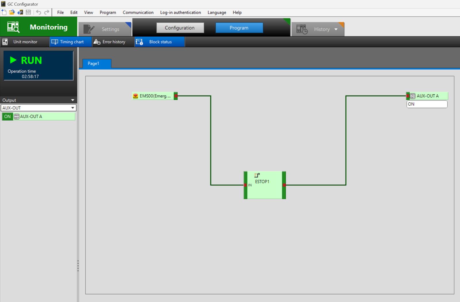
Result
Logic is successfully executed.
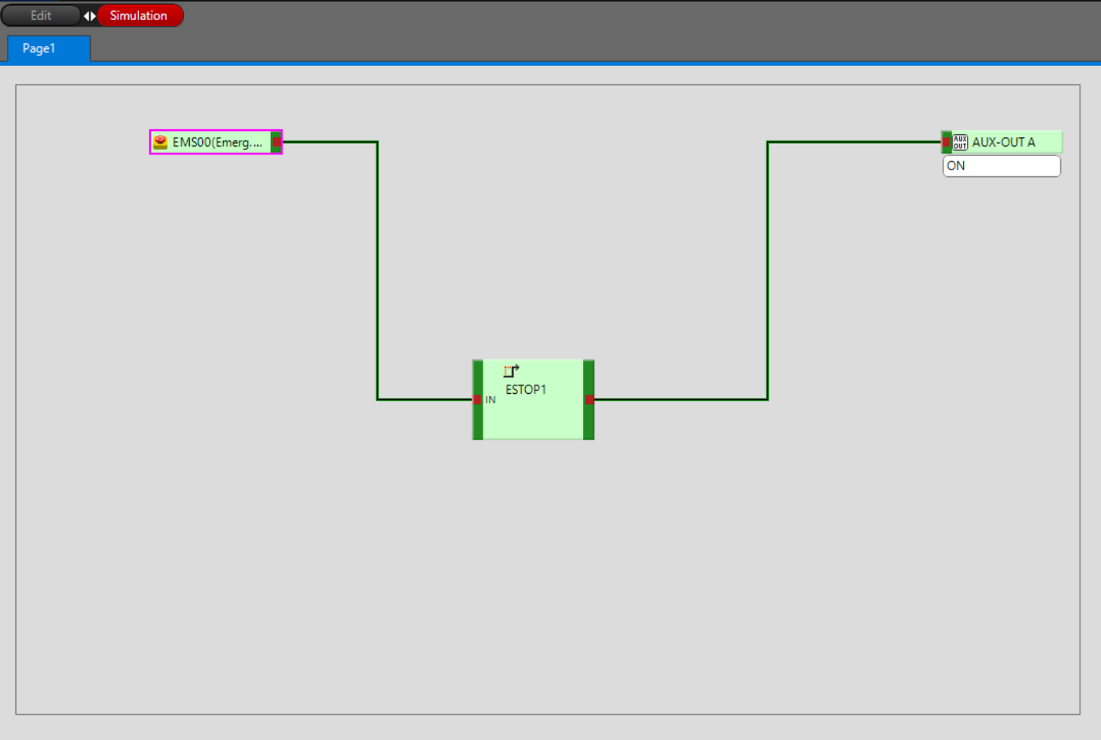
Trigger Signal
Double-click on EMS00 to invert the signal.
The operation is as shown in the figure below.
Return Back to Edit Mode
To switch to Edit Mode, simply click the Edit button.
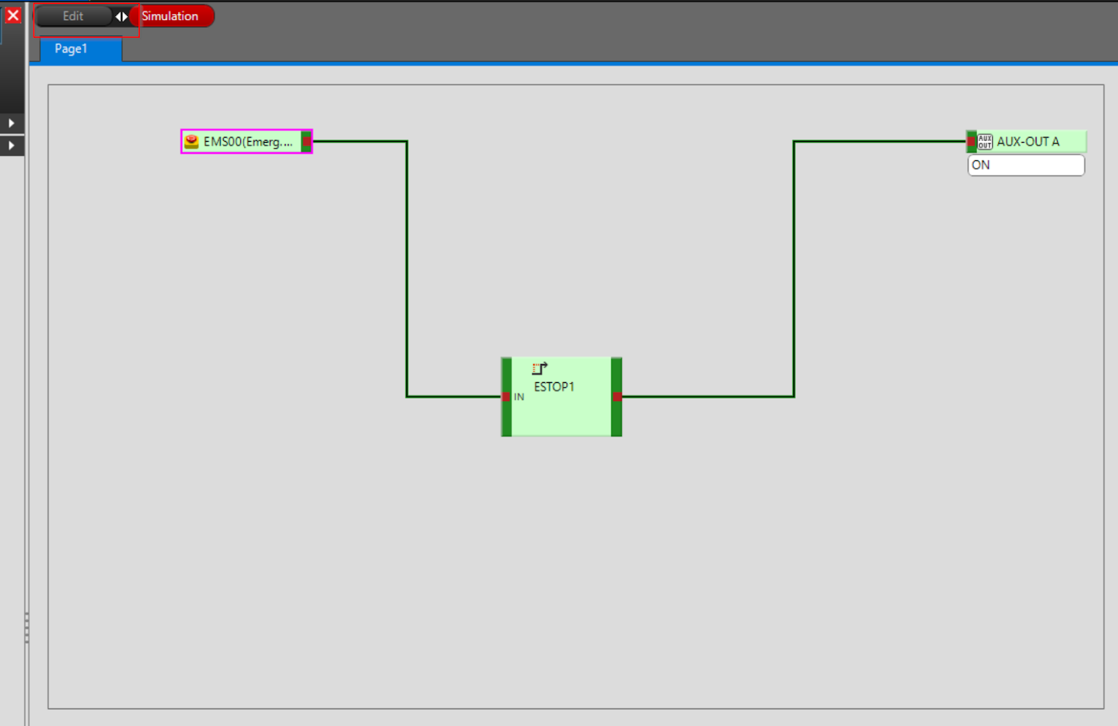
The operation is as shown in the figure below.
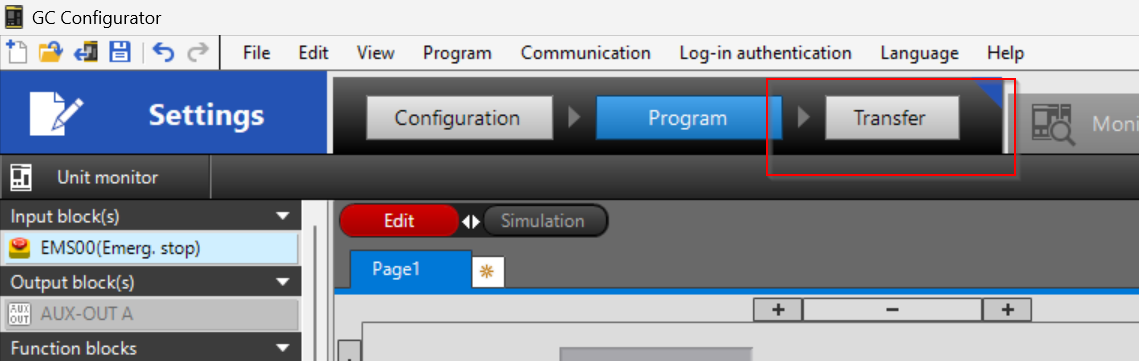
Transfer To GC1000
Now click on the “Transfer” button to transfer your project to the GC-1000.
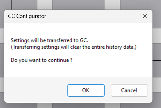
Proceed with Yes.
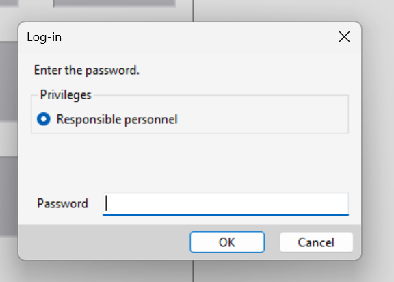
Enter a password; the default password is 1111.
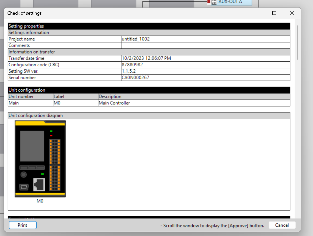
A confirmation screen for the settings will appear.
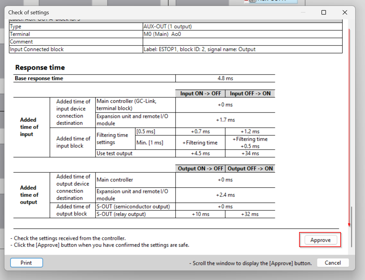
Scroll to the bottom and click the “Approve” button to transfer the project.
Just a second..
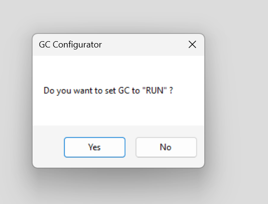
After the transfer is complete, the GC Configurator will ask you if you want to switch the GC-1000 to RUN Mode.Click Yes to switch the GC100 to run Mode.
Done!
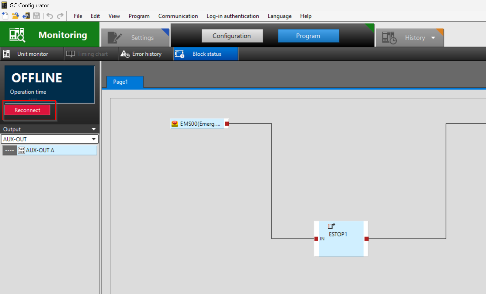
If Offline
If the GC Configurator is not operated for a certain period of time, the CPU connection will be disconnected and “OFFLINE” will be displayed.
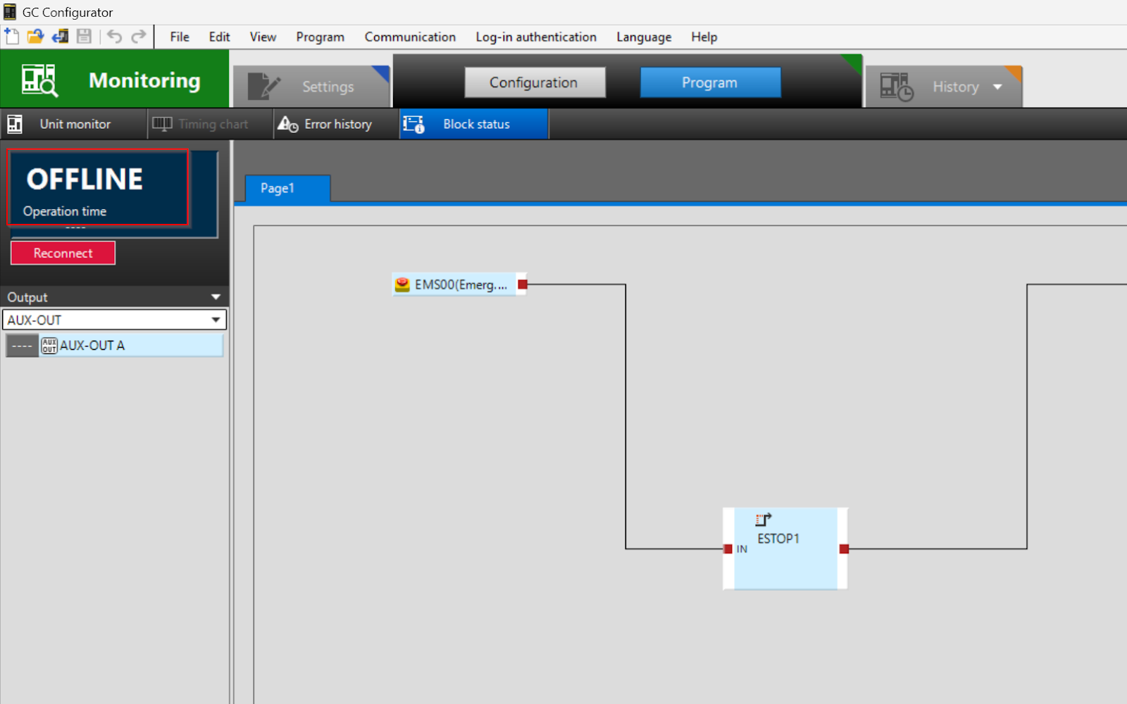
Click the Reconnect button to reconnect.
Done!
Unit Monitor
If you want to monitor the inputs and outputs of the GC-1000 Unit, click on Unit Monitor.
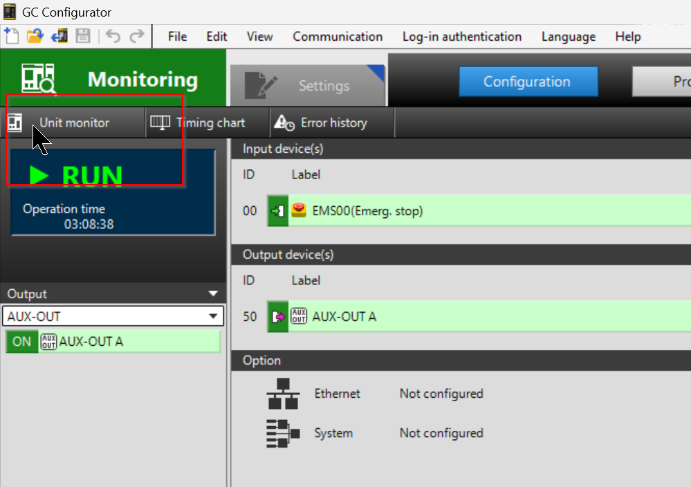
The Unit Monitor screen appears, allowing you to check the ON/OFF status of each Channel.
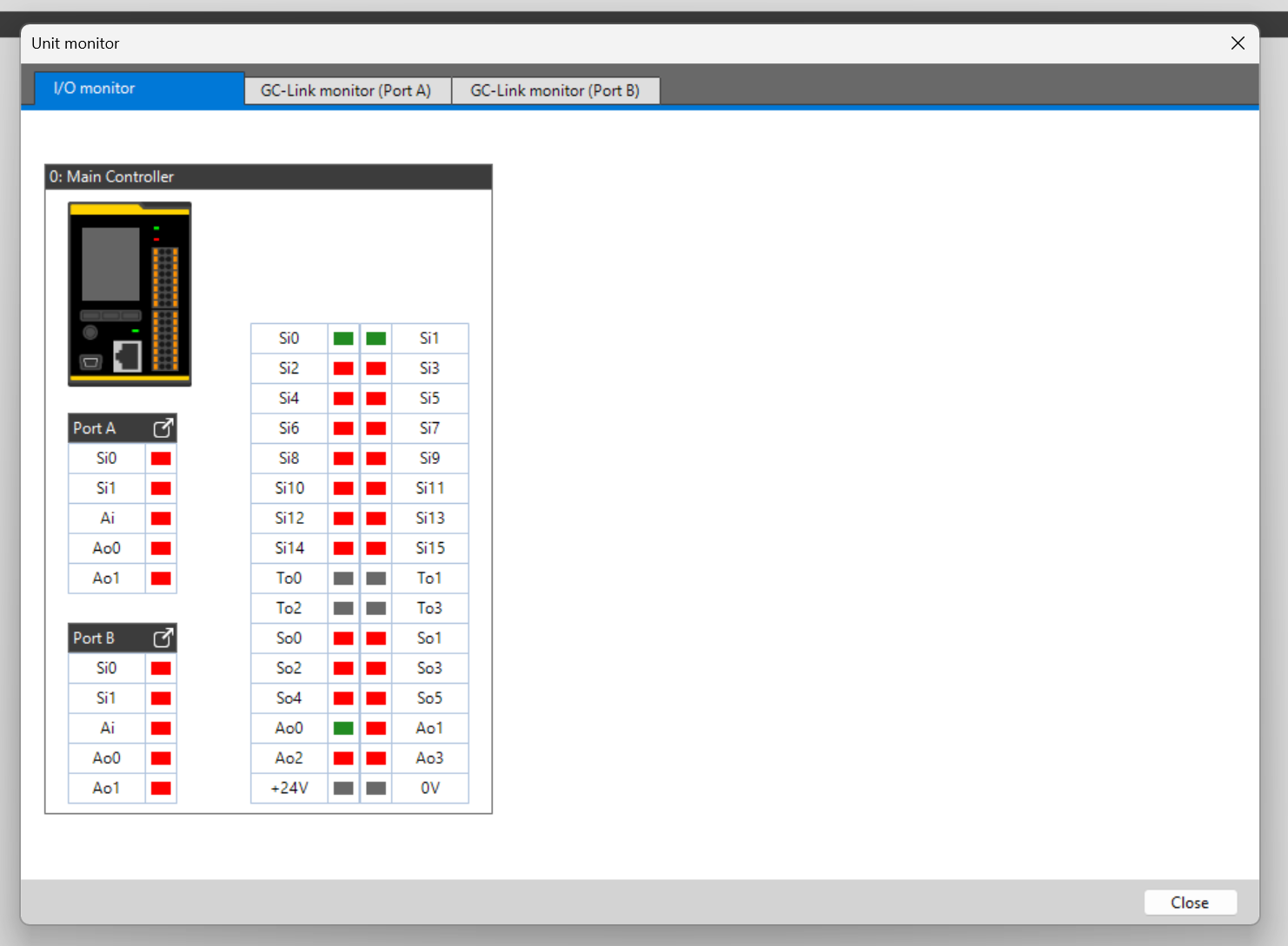
Change back to Edit Mode
If you want to switch from Online Mode to Edit Mode, click on the Settings button.
Done!
Operation
The actual operation of the GC-1000 with the emergency stop can be seen in this video.
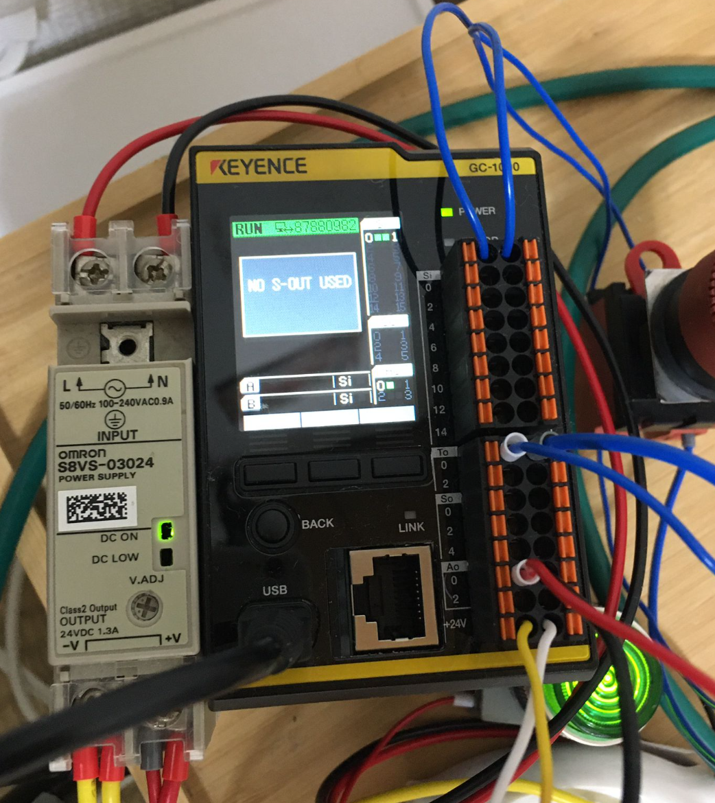
LCD Display
Now we will check the status of GC-1000 from LED Display.
Unit Monitor
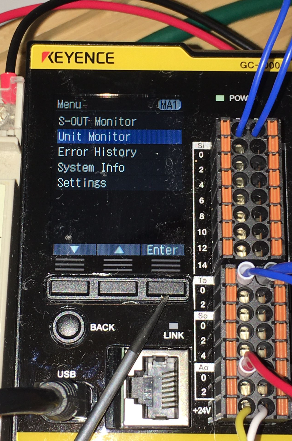
Click the Menu button.
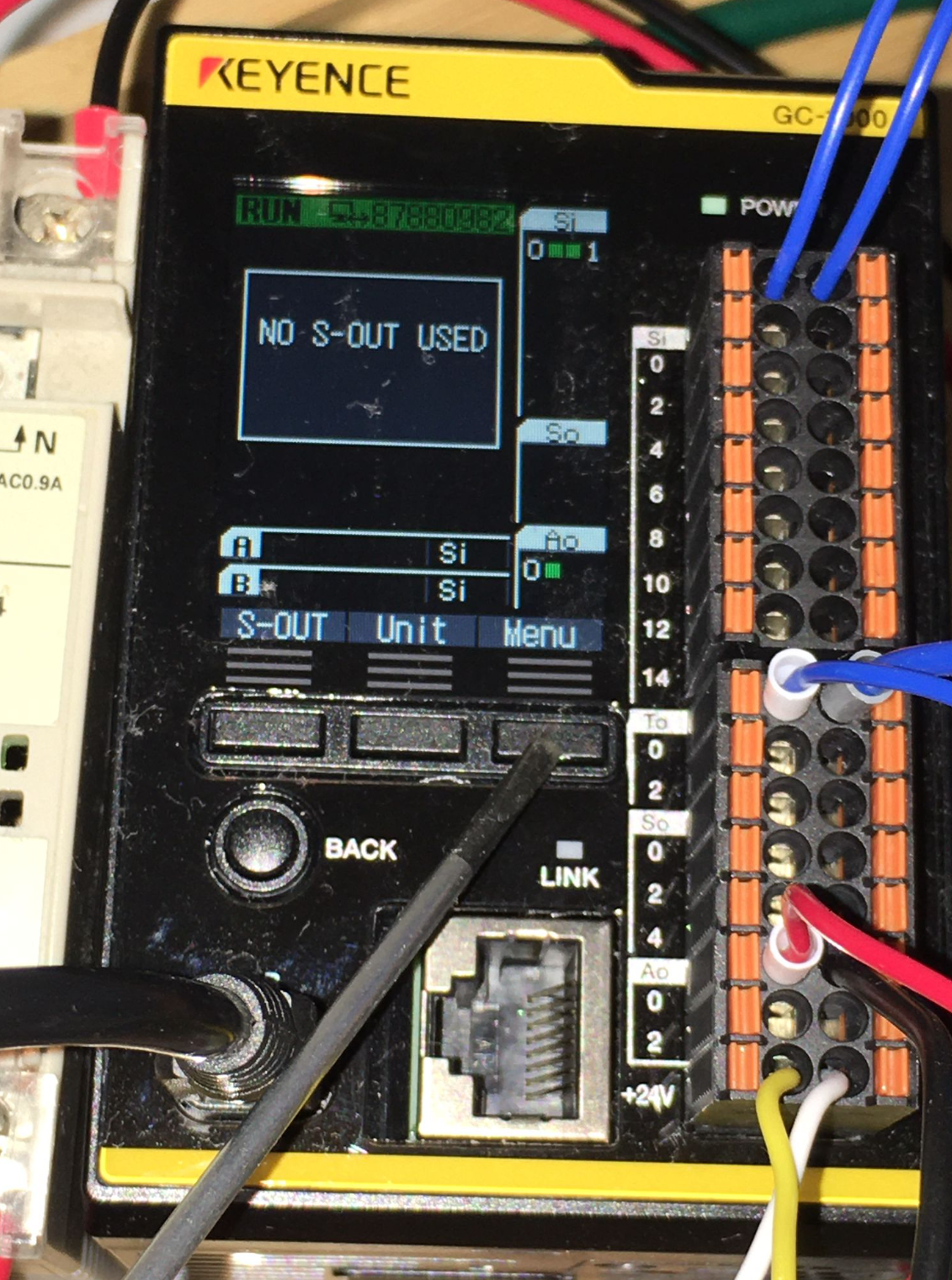
Go to Unit Monitor>Enter.
This shows the ON/OFF status of each terminal block at present.
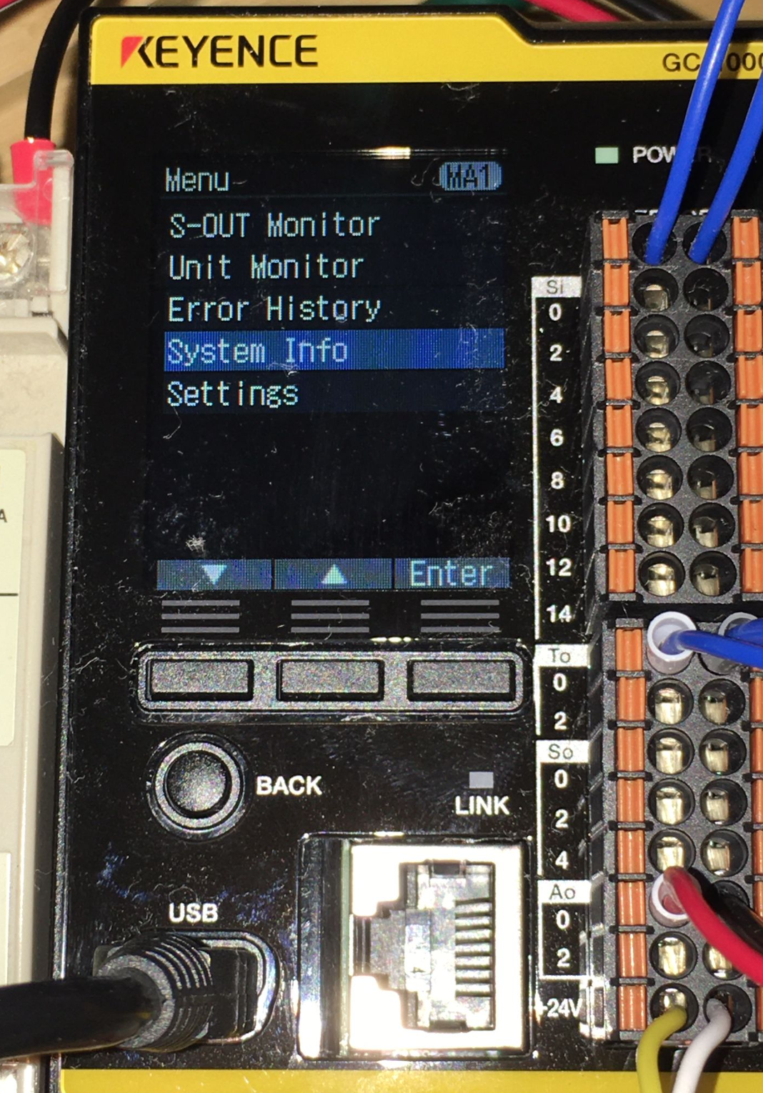
System Info
You can check the CPU’s internal information from the System Info Menu.
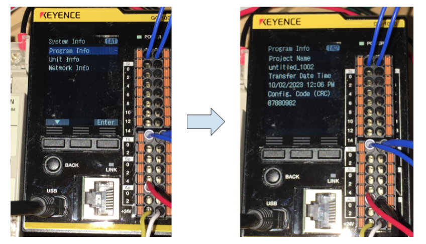
Program Info
In Program Info, you can check the name, CRC, etc. of the project running in the CPU.
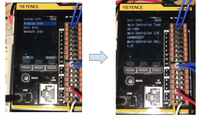
Unit Info
In Unit Info, you can check CPU type, firmware, etc.
Network Info
Network Info allows you to check the IP address, Mac address, etc. of the CPU.
