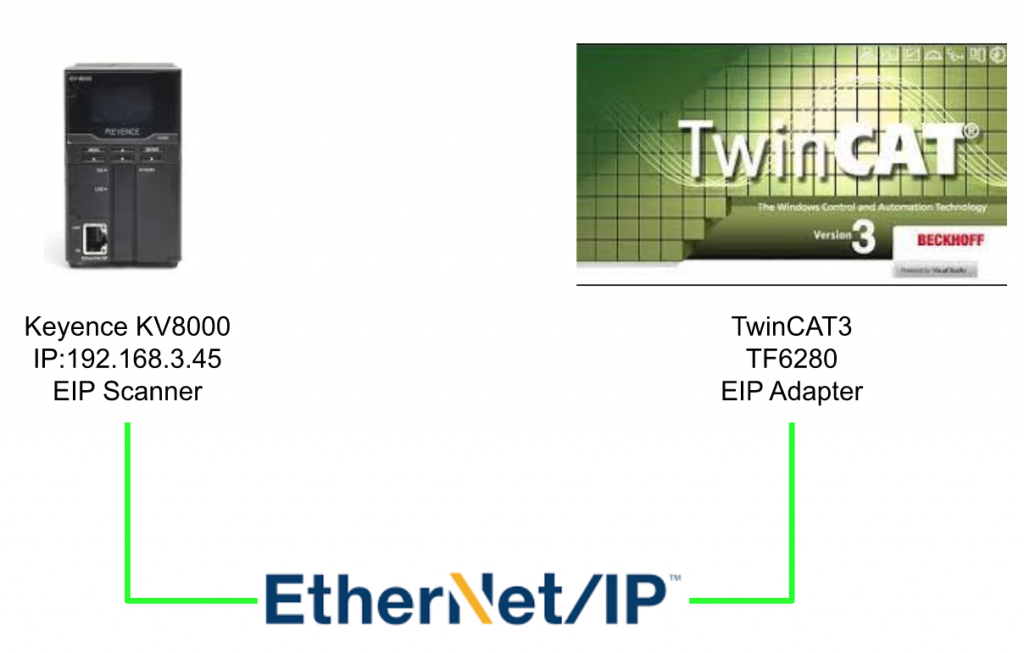
In this Tutorial I will show you how to configure a Ethernet/IP network with Beckhoff TwinCAT3 and Keyence KV-8000.Let’s Start!
Reference Link
http://soup01.com/en/category/protocol-en/ethernet-ip-en/
http://soup01.com/en/category/beckhoff-work_en/
Version-Japanese
Version-English
Implementation
TwinCAT3 Side
Let’s start from the TwinCAT3 Side.
Add PLC
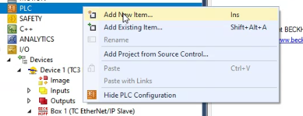
Go to PLC>RightClick and Add New Item.
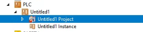
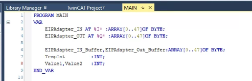
Insert a PLC and open the POU inside.
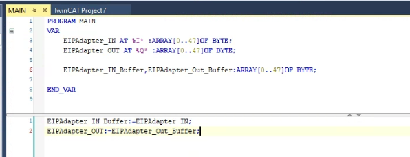
Create the process image for the Ethernet/IP communication, and use it inside the user program.
Add Ethernet/IP AdapterIP
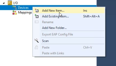
Go to I/O>Devices>Right Click and Add New Item.
Go to EtherNet/IP>select EtherNet/IP Adapter>OK.

Choose the interface that you are connected to in the ethernet/ip network and press ok.

Ethernet/IP Adapter is inserted.

Ethernet Adapter
Open the Adapter Tab and check if the interface is correct or not.

Sync Task
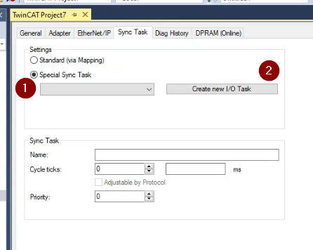
Open the Sync Task and set up the update time of Ethernet/IP Adapter Task.
Select the Special Sync Task>Create new I/O Task.
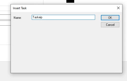
Input your task name and OK.
Set up the Cycle Ticks as 128ms.
Add a Connection Point
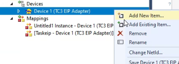
Right Click the Ethernet/IP Adapter that you inserted before> Add New Item.
Choose TC EtherNet/IP Slave>OK.
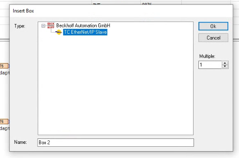
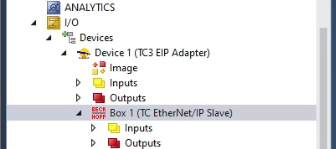
A connection point is inserted.

Adapter virtual IP
Double Click the Box1.
Open the settings Tab and configure the IP address and Network Mask in the 8000:21,8000:22.This is the IP address of your connection point.
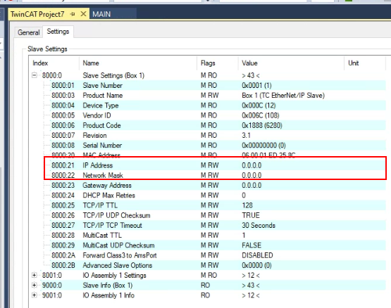
In this tutorial, 192.168.3.252/24 is configured.

Append IO Assembly
Now we can create the Assembly in the Connection Point. Right Click the Box>Append IO Assembly.
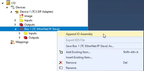
Assembly1 is created.
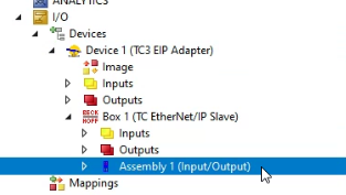
There are input and output items inside.

Insert Inputs
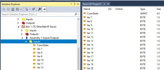
Right click the Inputs> Add New Item to configure your Input points.

32 Bytes data is configured in my tutorial, choose bytes,and enter 32 in the Multiple field.

32 of Input variables are created.
Try to Add the Array!
Let’s try to create the variables that all have the same data type in array format, click the “Create Array Type”.

We can configure the start and end index of our array.Let’s input 0 and 47 to create a Array with 48 Bytes.

Input the Name and Press ok to finish it.
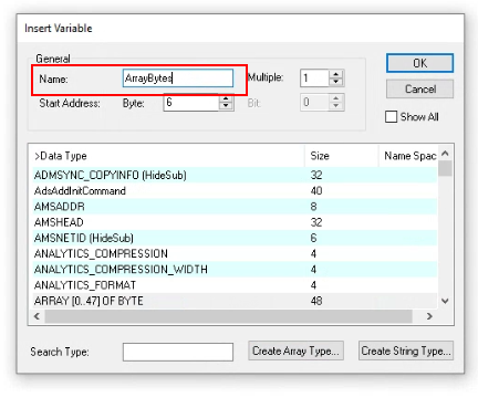
Array is created!.

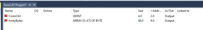
Add Ouput
Right click the Outputs> Add New Item to configure your Output points.
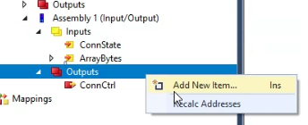
We can directly choose the ARRAY[0..47]OF BYTE because this variable type was created before.

Output Side is created also.
Data type is ARRAY[0..47]OF BYTE,same as Input.
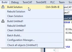
Build
Go to Build>Build Solution to compile your Project.
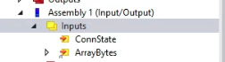
Link Input Variables
Now we can link the Inputs in the Assembly IO to the User program.
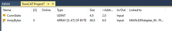
Click the Inputs.
Right Click the ArrayBytes>Change Link.

The variable that defined with AT %I* can be chosen here.

And you will see a X is shown while the following variable is Linked into your User Program.
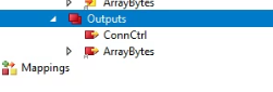
Link Output
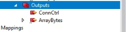
Now we can link the Outputs in the Assembly IO to the User program.
Click the Outputs.
Right Click the ArrayBytes>Change Link.
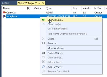
The variable that defined with AT %Q* can be chosen here.

And you will see a X is shown while the following variable is Linked into your User Program.

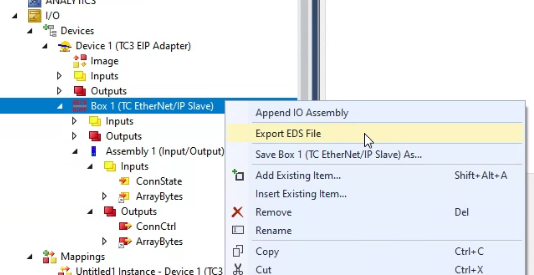
Export EDS
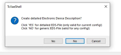
Go to Box1>Right Click>Export Files to export your Ethernet/IP Adapter.
There are 2 options for TwinCAT3 to generate the EDS File.
If YES=the EDS file that generated can be used in this configuration.
If NO=the EDS file that generated can be used in any configuration.
This time, we will use YES.
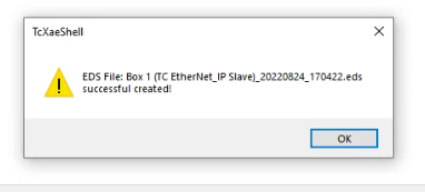
Choose the path that you would like to save.

Done!
Download
Finally,Download the Hardware Configuration to Runtime by Activate Configuration.
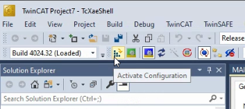
OK.

Press YES if you do not have enough Licenses.

Enter the Magic Code,OK.
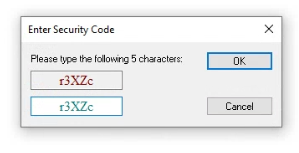
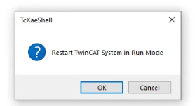
Restart your TwinCAT.
The Gear icon will change to Green if the Runtime is in Run Condition.

Login
Use Login to download the user program.

Yes.

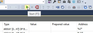
Start it!
Press Start to run your application!
KV8000 Side
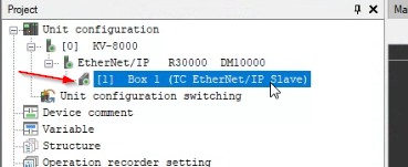
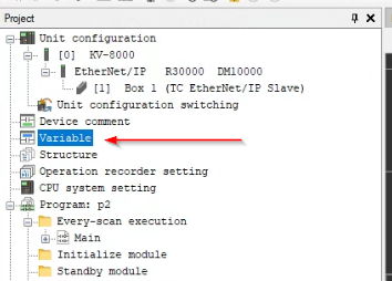
We can start to configure the Keyence KV-8000 Side Now.Go to Unit Configuration>KV-8000 and Click Ethernet/IP R3000 DM1000.

You can choose Manual or Auto Configuration here.
Auto Configuration=Scan the Ethernet/IP devices in the network and automatically insert to your Project.
Manual=Add the Ethernet/IP adapter one by one manually.
In this Tutorial, Manual is used.
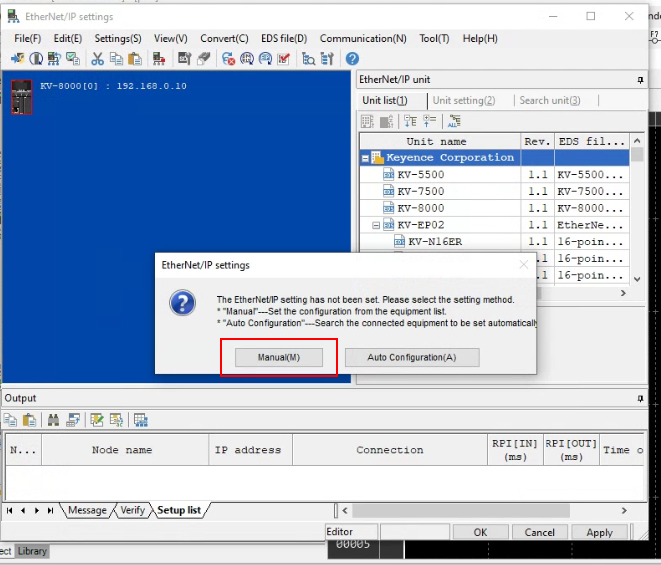
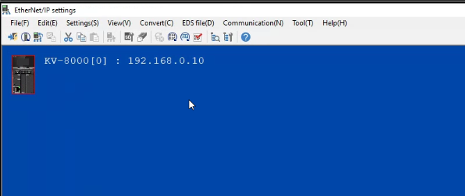
The Ethernet/IP Settings Screen is shown.
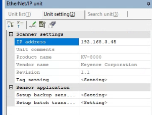
Cofigure Scanner
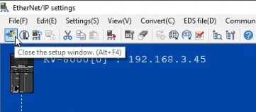
Double click the KV-8000 to configure the IP address of cpu.

You can set up the ip address on the right side.

192.168.3.45 is set in this tutorial.
Register EDS
The next Step is to register the EDS file.
Go to the Ethernet/IP Unit>Unit List>Right Click in the Empty Field>Register EDS File.
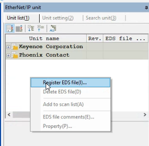
Choose the EDS File that exports from TwinCAT3.

Because we do not have the icon file, a warning is shown.
choose Use default icon and OK.

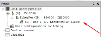
TwinCAT3 Ethernet/IP Adapter is inserted in the Unit List.

Insert in your network
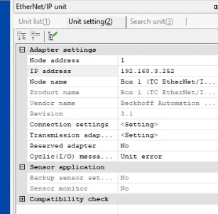
Now we can insert theTwinCAT3 Ethernet/IP adapter in the network.
Double click it or Drop it on the blue screen area, and set the IP address of the adapter.

And also we can get more settings on the Unit setting in the Right-Hand side.
Press the “-” button that near the Adapter, the In/Out address is shown.
IN_129 is input and started from W00-19,OUT_130 is output and started from W1A-33.
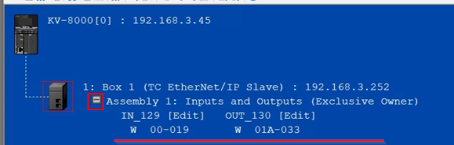
What is W?
W is Link Register for communication ,and the values are saved in W Davies.The address is counted in Hex format.
For Example, we set IN_129 from 00-19.
It means that the Devices are started from W00,W01..W09 and the Next one is W0A but not W10.Then W0A,0B,0C,0D,0E,0F .
Connection Settings
Go to Settings>Connection settings to get more parameters about the Adapter.
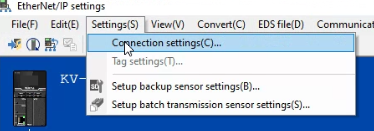
RPI,Connection Type,Instance Number..Etc can be set in here.

For Example, we can change the connection type to twincat3 from Exclusiv Owner to Input Only or Listen Only.

Finish it
Click the “Close the setup window” button or Alt+F4 to close the Ethernet/IP settings screen.
Click the “Exit from the Unit Editor” button or Alt+F4 to close the Unit Editor.

Press Yes to save your configuration.

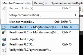
Download
Now we can Go to Monitor/Simulator ->Transfer to PLC -> Monitor mode to transfer the project to KV-8000.
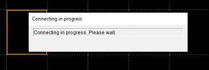
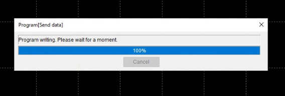
Please wait a minute..
Select all the transfer items and Execute.

Please wait a minute..
Result-1 Cannot Connect..
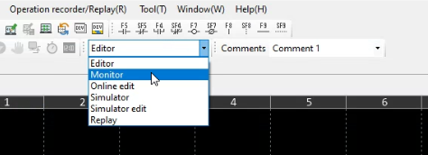
Now we can see the result.Go to the Editor of the KV Studio and select the Drop list to change the mode from Editor to Monitor.
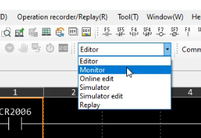
but you can see a Red “X” is shown. It means that the communication is not established
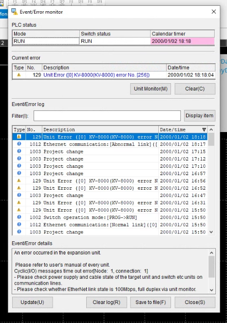
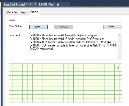
And also the Common Error Popup is shown and we can see more Detail from the Detail Button.
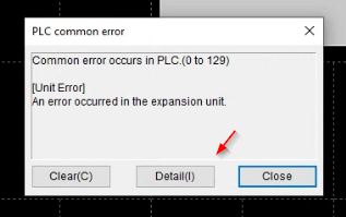
An Error message of Cyclic IO is displayed here.It means that the communication between TwinCAT3 and KV-8000 had a problem.
Why?
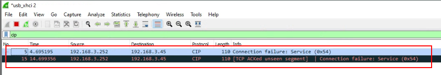
Open the WireShark to make a network capture, and set the Filter as CIP. There is an Error response From 192.168.2.252(TwinCAT3) to 192.168.2.45(KV8000).
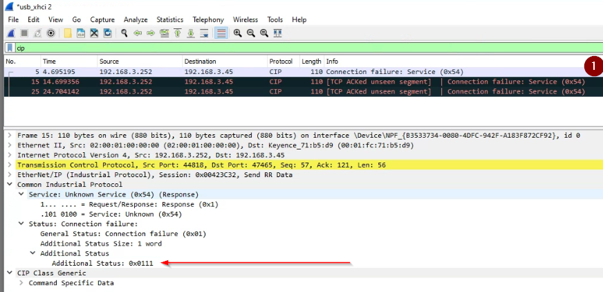
Service Request 0x54,Status Connection failur,mGeneral Status=0x1 and Addition status=0x0111 is shown inside the Error Package.
What is 0x54 and General Status=0x1,Additional Status=0x1111?
0x54=Forwad_Open
Firstly,0x54 is the Forward_Open Request(Max 511 Bytes). In an Ethernet/IP network, Scanner will send the Forward_Open request to each Adapter before starting the IO data exchange, and the Adapter will check if all these connection parameters are correct not.
So – The connection parameter that was configured in Scanner Side is wrong, and TwinCAT3 refused this Connection.
General Status=0x1,Additional Status=0x1111
General Status=0x1 Additional Status=0x1111 is returned from Adapter(TwinCAT3). Reference by CIP specification, this error is RPI not Supported.Before I told you the solution, Let’s see what is RPI first.
RPI=Requested Packet Interval, it is a time interval for an Originator to request a new packet – you can imagine it as the update time.
This RPI is configured as ms ,32 bit Integer.
Finally,the reason for RPI Not Supported is – TwinCAT does not accept the RPI setting from Scanner Side(KV8000).
Let’s Fix it!
We can fix it now.Go back to the KV Studio, and open the Connection Settings and check the RPI setting.64.0ms is configured now.

In the TwinCAT3 side, the Task Eip is 128ms.So – TwinCAT3 side can only update the Ethernet/IP control cycle in each 128ms, and KV8000 is trying to request a new package in every 64.0ms.It make sense why TwinCAT3 refused this connection.
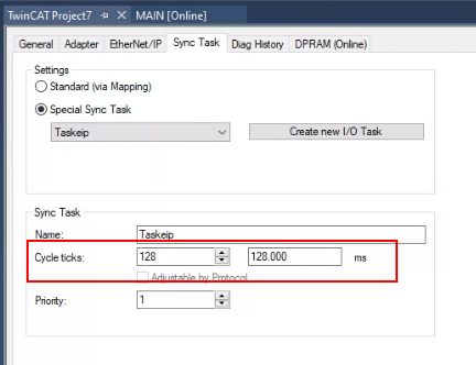
Let’s change the cycle ticks to 32 ms.

Download the Project again on both sides.
Result-2
KV8000 Side
Let’s Change the Mode to “Monitor” in KV Studio again.
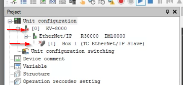
The Box1(TwinCAT3) ICON is changed to Green!
TwinCAT3 Side
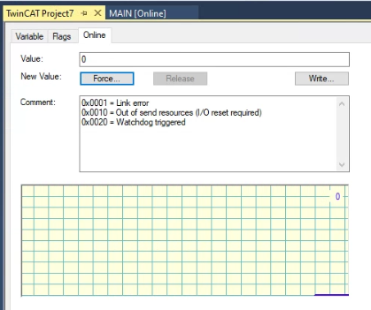
Let’s check in the TwinCAT3 side again. Go to Device1>Inputs>Devstate.
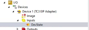
0=no any error information.
Let’s check the Box1>Inputs>State also.

0=no any error information.
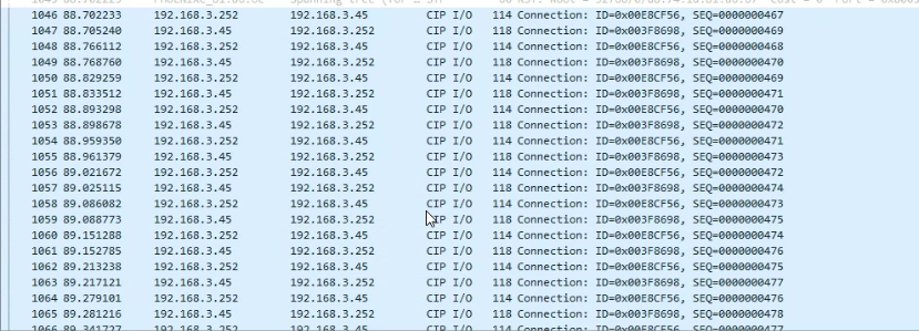
CIP I/O packages are transferred if you capture it by wireshark!
Summary
Now we can summarize what we did in this tutorial.
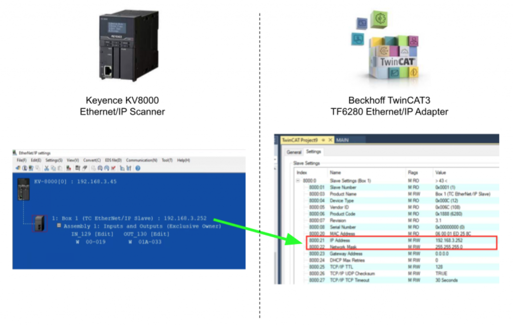
IP
The IP address of the Ethernet/IP Adapter setting in KV Studio must be the same as 8000:21 and 8000:22 on the TwinCAT3 side.
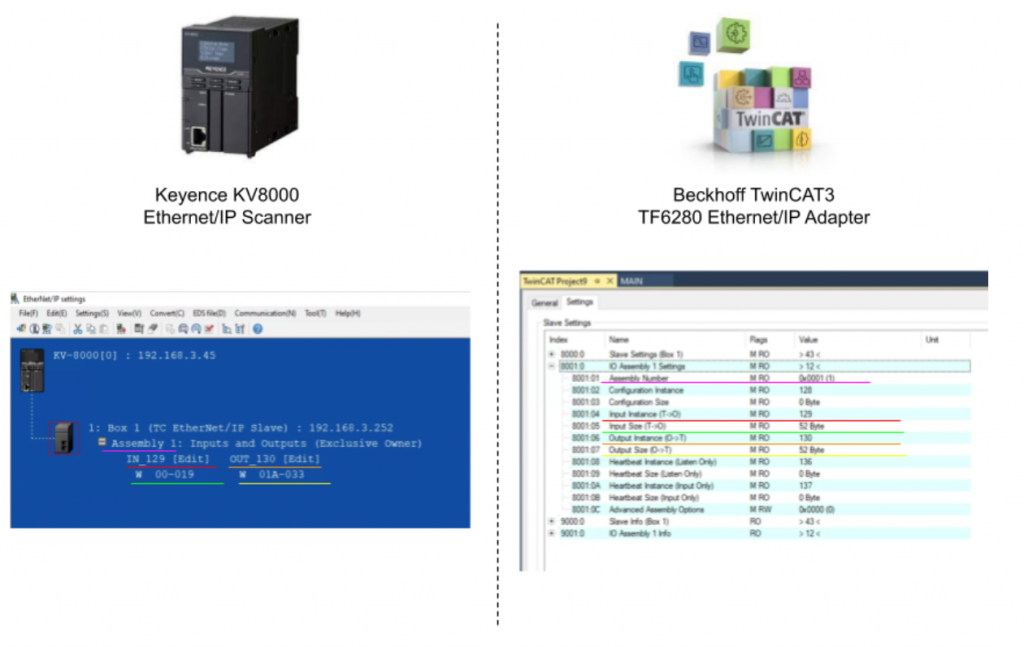
Assembly
Pink line is Assembly number = Index 8000:01 in TwinCAT3 Side.
Red line is the input instance number = Index 8000:04 in TwinCAT3 Side.
Green line is the total bytes of Input instance = Index 8000:05 in TwinCAT3 Side.
Orange line is the Output instance number = Index 8000:06 in TwinCAT3 Side.
Yellow line is the total bytes of Input instance = Index 8000:07 in TwinCAT3 Side.
Bonus
Here is the Bonus.In the above we used wireshark to check the connection, and now we will make some simple program to check it.
KV8000
Define Variable
Go to KV Studio>Variable.
We can define the variable in here and Let’s create a variable with an Array type that is named ArrayDataFromTwinCAT.
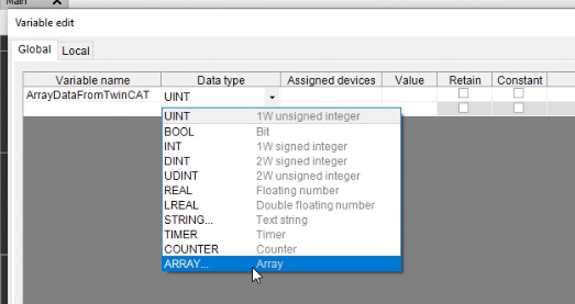
Choose the Data type as UINT and 26 as your Array Size.
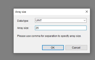
Set W00 in the Assigned devices field.

“Set device name W00 to W019” is shown. It means the address of this array variable is from W00 to W19.

Do the same operation in the Output Side.

Insert Program
Now we can create some programs.Right click in the Editor window>insert Box script.
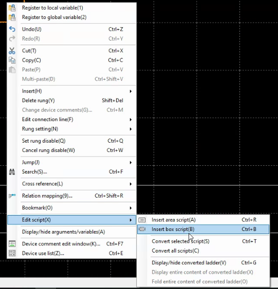
insert CR2006 contact in the program, and CR2006 is a 1 second Clock pulse.

A +/- 1 program is created. *The programming Style of Keyence script and IEC61131-3 ST is 100% different.

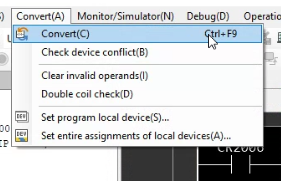
Compile
Go to Convert>Convert and Download the project into your KV-8000 again.
TwinCAT3
Now the time of TwinCAT3 Side.
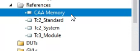
Add Library
Add CCA Memory from Reference.You can imagine this library contains some memory operate function like BMOV.
Program
Define some variables inside the VAR area.
MEM.MemMove is used to transfer the memory in a group. Because the Process IO in the TwinCAT3 side is defined as Bytes and in the KV8000 side, the variables are defined as WORD.
We will move the word data to a buffer and then transfer it by MEM.MemMove.
For MEM.MemMove, pSource is the the pointer of your Data from,pDestination is the pointer of your Data to, and we can use ADR() function to get this memory pointer.

Result
As you see, the Value1, Value2 in TwinCAT3 are changed.

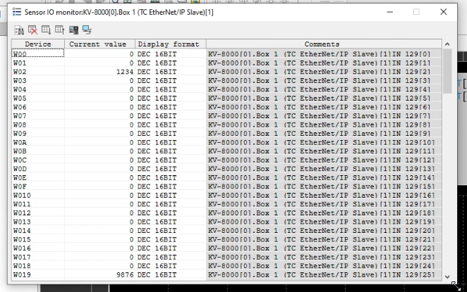
Now Let’s see in the KV Studio side and Click the Box1(TwinCAT3).
All the value in this connection can be viewed in this Screen and you can see the data are exchanged between TwinCAT3 and KV-8000.
And Also , you can right Click the Box Script>Registration monitor window.

All the variables used in the Box can be viewed also.
