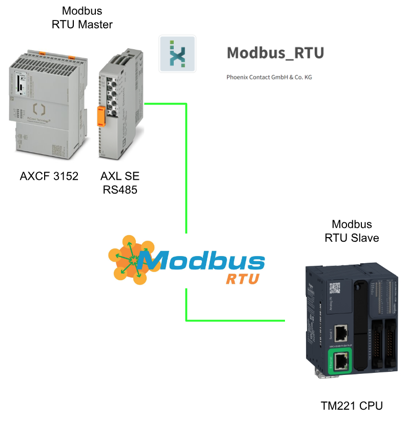
In this article, we will combine PhoenixContact’s AXL SE RS485 with the Modbus_RTU library to set up a Modbus RTU Master to communicate with the Modbus RTU Slave in Schneider’s TM221.
Let’s get started!
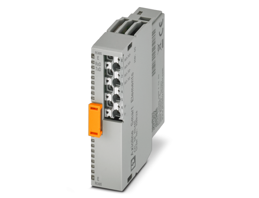
AXL SE RS485
This Smart Element is used as a standard I/O device with a serial interface (RS485) on a bus system.
- Serial input/output channels in RS-485 format
- Transmission speed can be set up to 230,400 bps
- Configurable number of data bits, stop bits, and parity
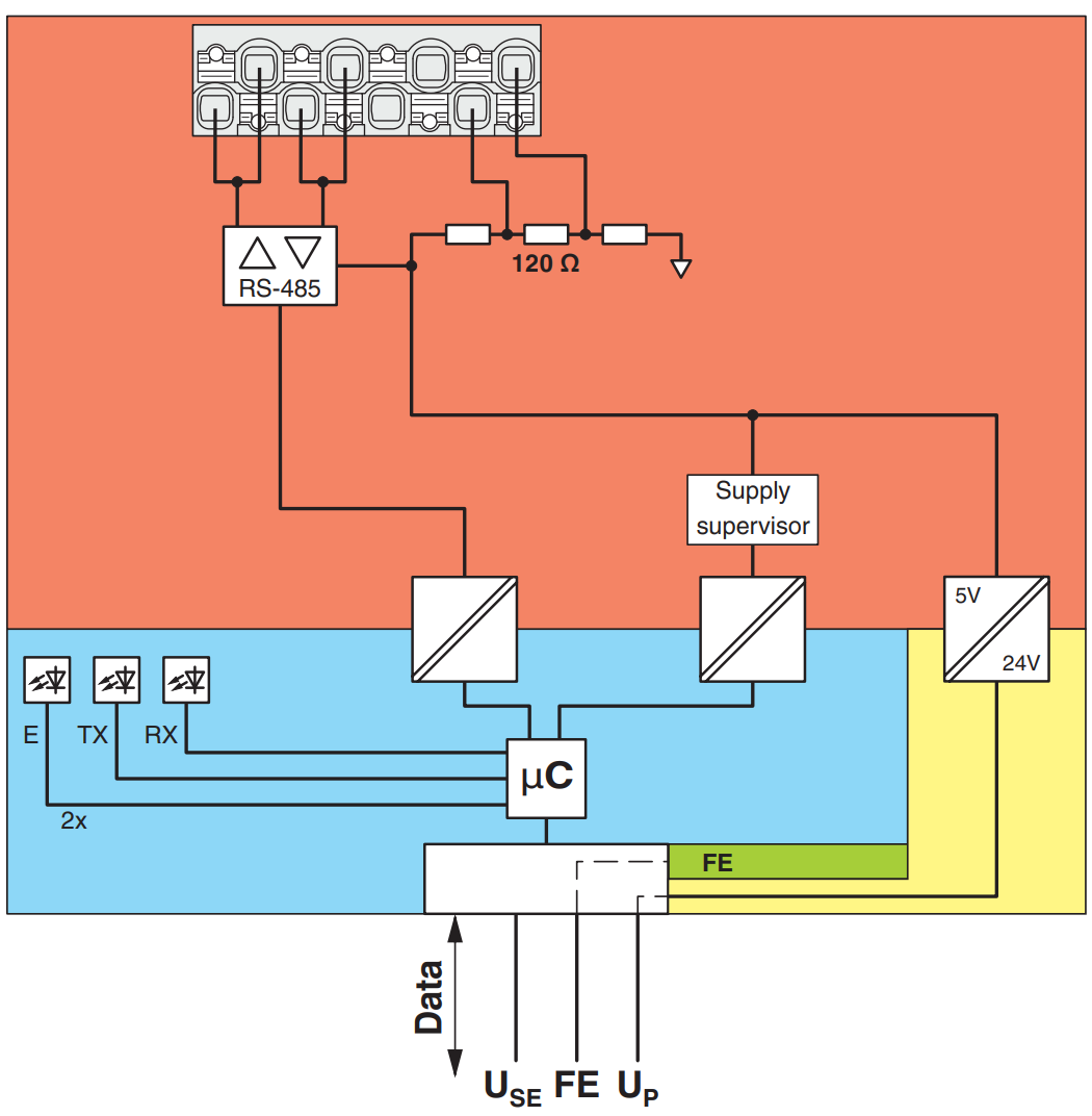
Internal circuit diagram
Here is an internal diagram of the AXL SE RS485.
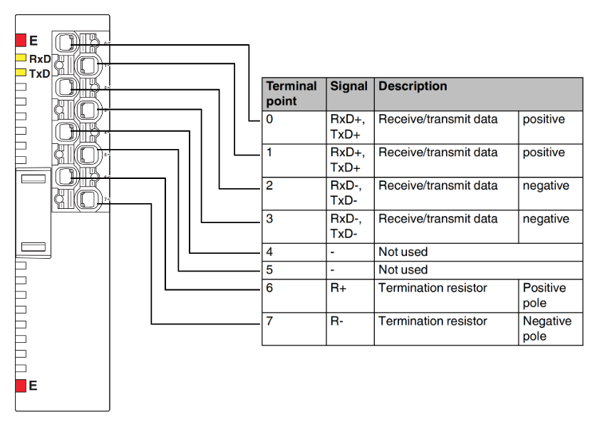
Layout
This is the Layout for the AXL SE RS485 module.
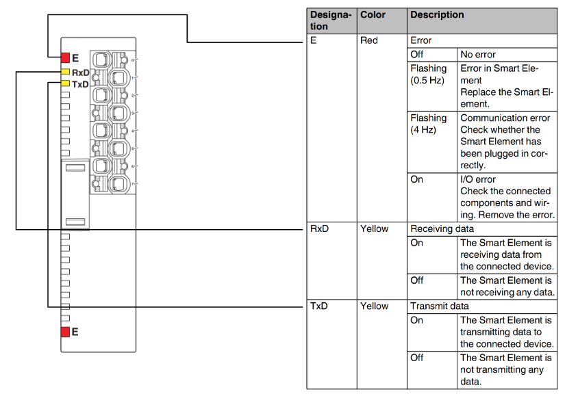
LED
This is what the LEDs on the AXL SE RS485 module mean.
Wiring Example
With RS-485, an existing network consisting of two signal lines can be used to create a multi-device network. Devices are connected using twisted-pair, commonly shielded data cables, and terminators are attached to the data cables at both ends of the RS-485 network.
For this purpose, the termination resistors built into the Smart Element can be used via the connections R+ and R-.
It is important to note that the AXL SE RS485 supports only half-duplex transmission. Do not allow data to be transmitted from more than one device at the same time.
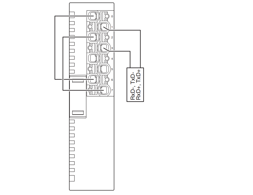
Smart Element as the network endpoint
Wiring example when AXL SE RS485 is used as an Endpoint device in a network.
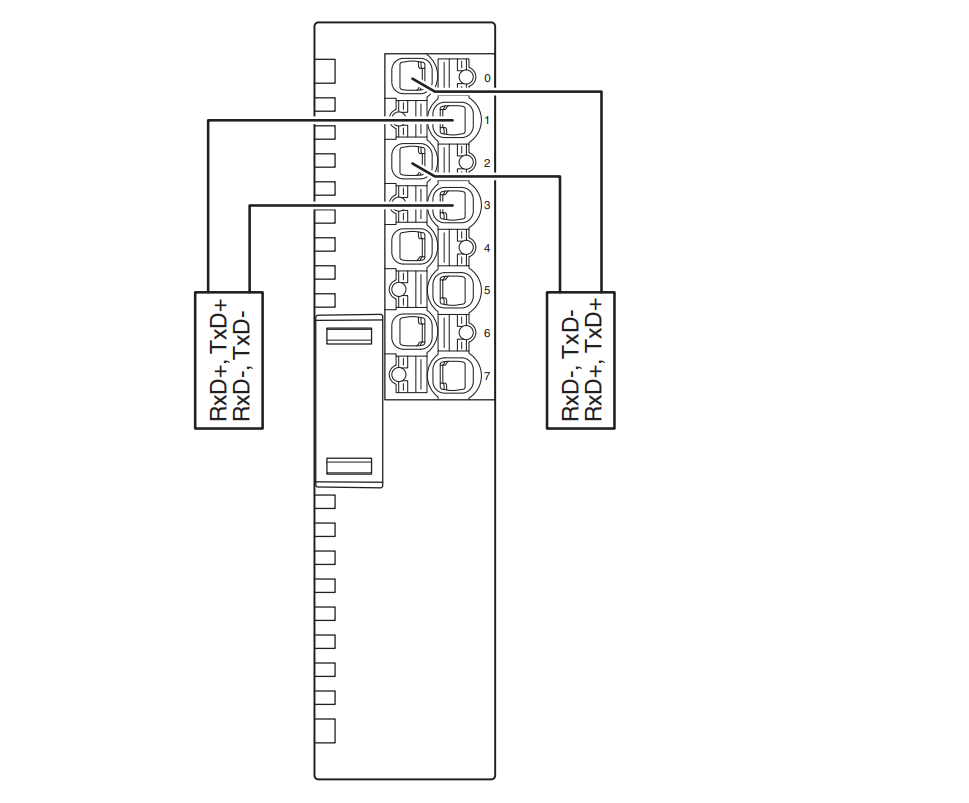
Smart Element in the middle of a network
Wiring example when AXL SE RS485 is used as an intermediate device in a network.
Download Library
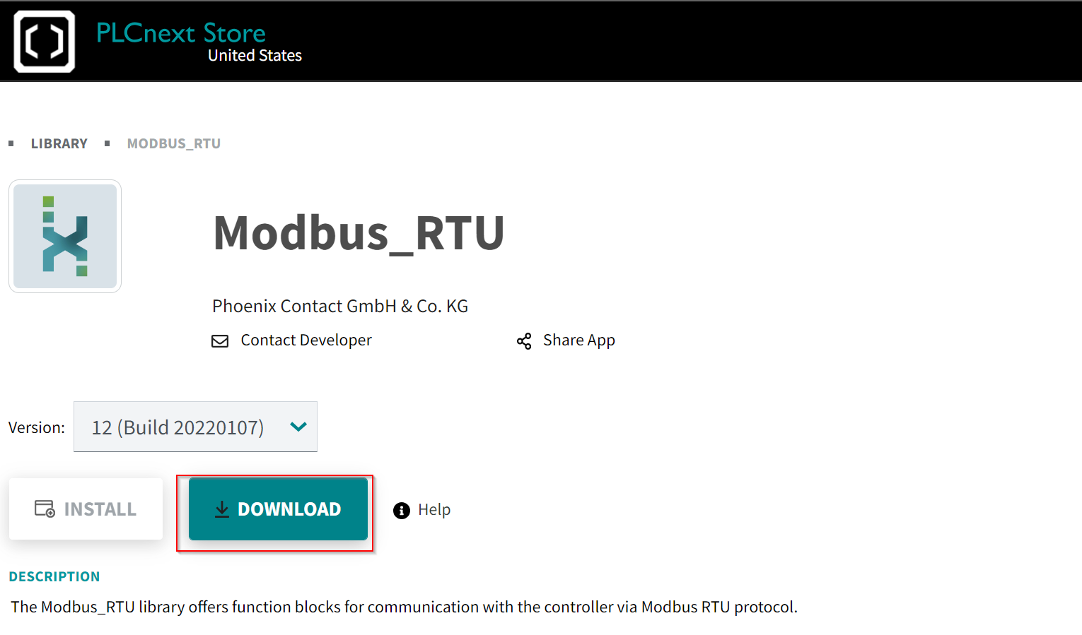
Download the Modbus RTU library from the Link below to the PLCNEXT Store.
https://www.plcnextstore.com/us/app/1432
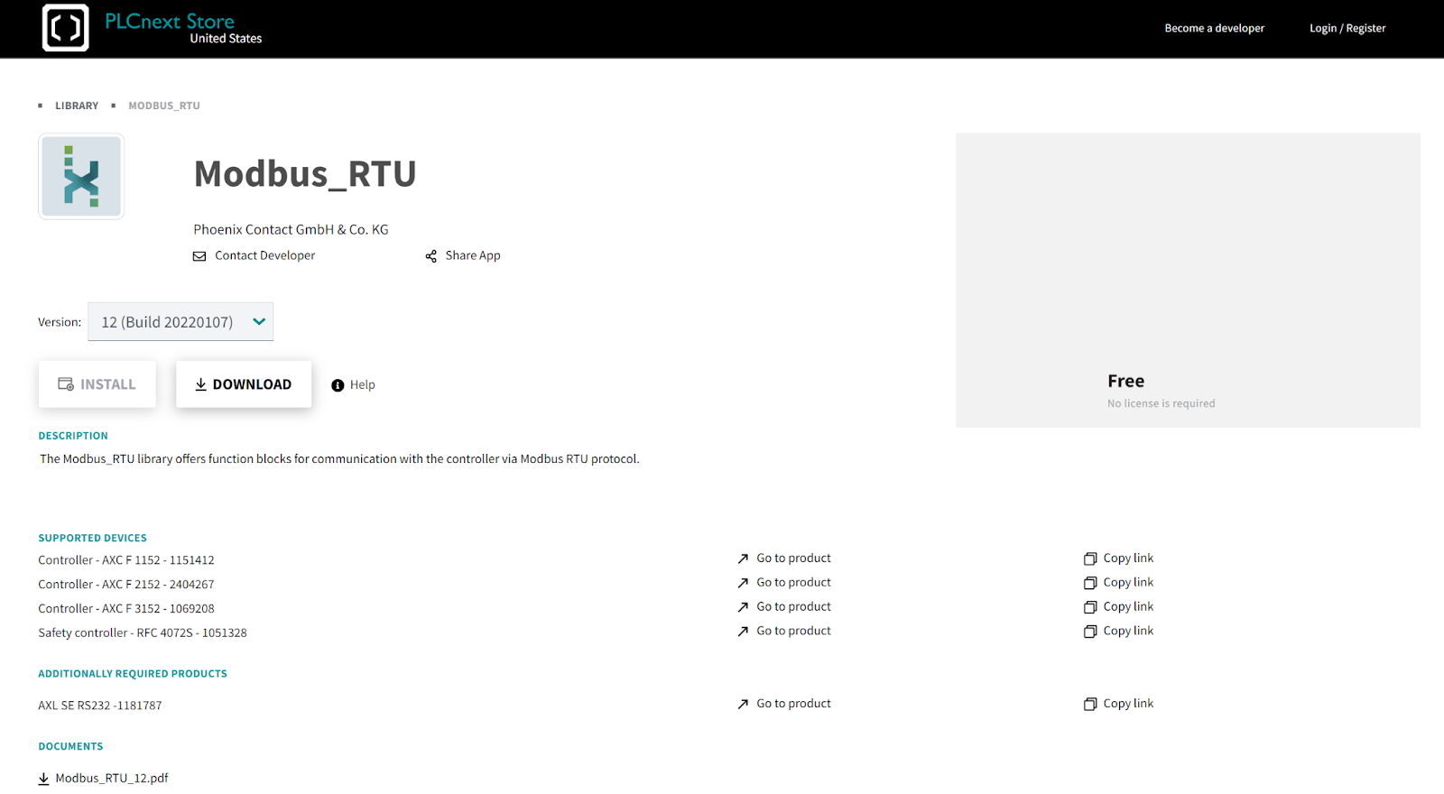
Click the Download button.
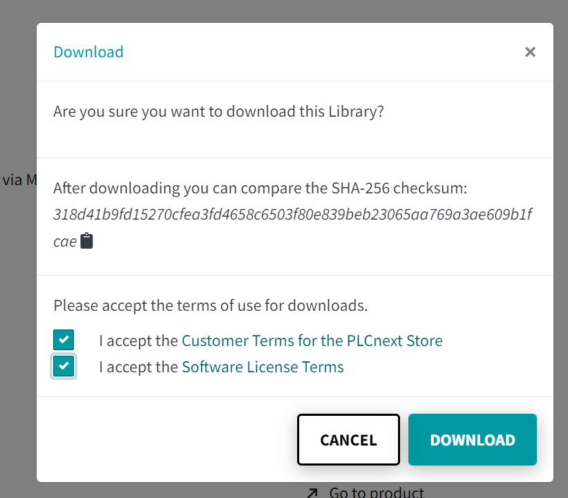
Agree to the license and download the library.
A Zip File like this was downloaded.

Function Block/Data Types
It is impossible to describe all Function Blocks included in the library, so only the Function Block used in this article will be described.
MB_UDT_RTU_FC_DIAG
| MB_UDT_RTU_SND_DIAG : STRUCT iState : INT; wDiagCode : WORD; wAddDiagCode : WORD; bControlByte0 : BYTE; bStatusByte0 : BYTE; END_STRUCT; |
MB_UDT_AXL_SE_RS485_DIAG_MASTER
| MB_UDT_AXL_SE_RS485_DIAG_MASTER : STRUCT udtMB_AXL_RS_UNI_REC_Diag : MB_UDT_RTU_REC_DIAG; udtMB_AXL_RS_UNI_SND_Diag : MB_UDT_RTU_SND_DIAG; udtMB_RTU_Master_Diag : MB_UDT_RTU_MASTER_DIAG; END_STRUCT; |
MB_UDT_RTU_REC_DIAG
| MB_UDT_RTU_REC_DIAG : STRUCT iState : INT; wDiagCode : WORD; wAddDiagCode : WORD; bControlByte0 : BYTE; bStatusByte0 : BYTE; END_STRUCT; |
MB_UDT_RTU_SND_DIAG
| MB_UDT_RTU_SND_DIAG : STRUCT iState : INT; wDiagCode : WORD; wAddDiagCode : WORD; bControlByte0 : BYTE; bStatusByte0 : BYTE; END_STRUCT; |
MB_UDT_RTU_MASTER_DIAG
| MB_UDT_RTU_MASTER_DIAG : STRUCT iState : INT; wDiagCode : WORD; wAddDiagCode : WORD; END_STRUCT; |
arrModbus2_W_1_125
| arrModbus2_W_1_125 : ARRAY [1..125] OF WORD; |
arrModbus2_W_1_123
| arrModbus2_W_1_123 : ARRAY [1..123] OF WORD; |
MB2_AXL_RSUNI2_ARR_B_0_19
| MB2_AXL_RSUNI2_ARR_B_0_19 : ARRAY [0..19] OF BYTE |
udtModbus2_Data
| udtModbus2_Data : STRUCT (* Modbus handling *) (* Send Modbus request *) xSendRequest : BOOL; (* Indicates FC wants to send a Modbus request *) xNDR : BOOL; (* New modbus response received *) xBusy : BOOL; (* FC only operates if not busy *) xReset : BOOL; (* Reset from input on master FB *) tTimeout : TIME; (* Input tTimeout of the Modbus_Master FB*) (* General Modbus data *) uiSlaveAddress : UINT; (* Address of the Modbus slave *) iFunctionCode : INT; (* Function Code by the Master *) uiStartAddress : UINT; (* Starting address in the Modbus register table *) iSndDataCount : INT; (* Required data length from FC *) iExpDataCount : INT; (* Expected data length depending of the function code number OF bits or words *) uiRcvdDataCount : UINT; (* Received bytes from Serial IF / UINT for the range higher than 127 *) arrData : arrModbus2_W_1_125; (* Modbus telegram *) (* Failure handling (master outputs) *) xMasterActive : BOOL; (* Interface is ready *) xMasterBusy : BOOL; (* Interface is busy *) xMasterError : BOOL; (* Error indication *) wMasterDiagCode : WORD; (* Diagnostics code *) wMasterAddDiagCode : WORD; (* Additional diagnostics code *) xMB_Error : BOOL; (* Exception Code Response *) xFC_Busy : BOOL; (* FC catches bit IF request and not xFC_Busy *) END_STRUCT; |
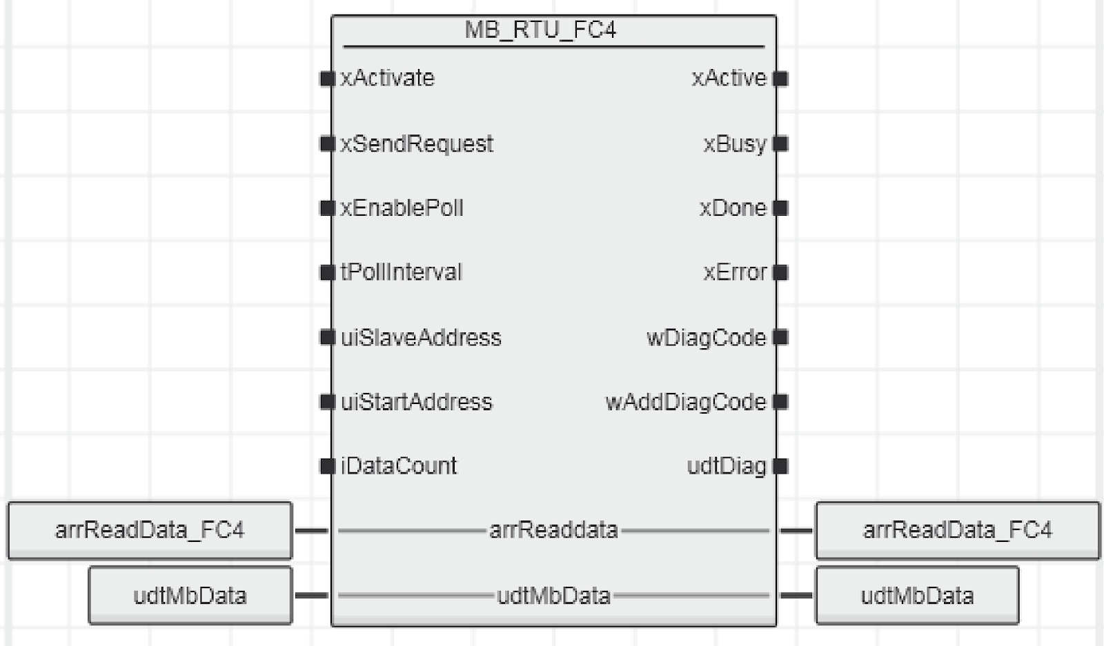
MB_RTU_FC4
This Function Block reads the Input Register from the Modbus Slave.
VAR_INPUT
| Variable Name | Type | Description |
| xActivate | BOOL | True=Enable FB |
| xSendRequest | BOOL | A rising signal sends a send request to the master blockThe falling signal deletes the current Modbus error and still resets the FB output. |
| xEnablePoll | BOOL | A start-up signal to start the cycle polling. |
| tPollIntervall | TIME | Transmission time interval when xEnablePoll is enabled |
| uiSlaveAddress | UINT | Specify the Slave ID to communicate with (1 to 255) |
| uiStartAddress | UINT | Specify the starting address for read with Slave |
| iDataCount | INT | Specify the number of devices to be read in Slave (1 to 2000) |
VAR_OUTPUT
| Variable Name | Type | Description |
| xActive | BOOL | True=FB enabled. |
| xBusy | BOOL | True=FB is running |
| xDone | BOOL | True=Request is sent and response from the slave is successfully received |
| xError | BOOL | True=FB with error, see wDiagCode and please find wAddDiagCode for details |
| wDiagCode | WORD | FB Diagnostic Information |
| wAddDiagCode | WORD | FB Diagnostic Information2 |
| udtDiag | MB_UDT_RTU_FC_DIAG | Structure variable with internal variables for diagnostics |
VAR_INOUT
| Variable Name | Type | Description |
| arrReadData | arrModbus2_W_1_125 | The structure will contain Modbus data. |
| udtMBData | udtModbus2_Data | Interface to communicate with MB_AXL_SE_RS485_Master |
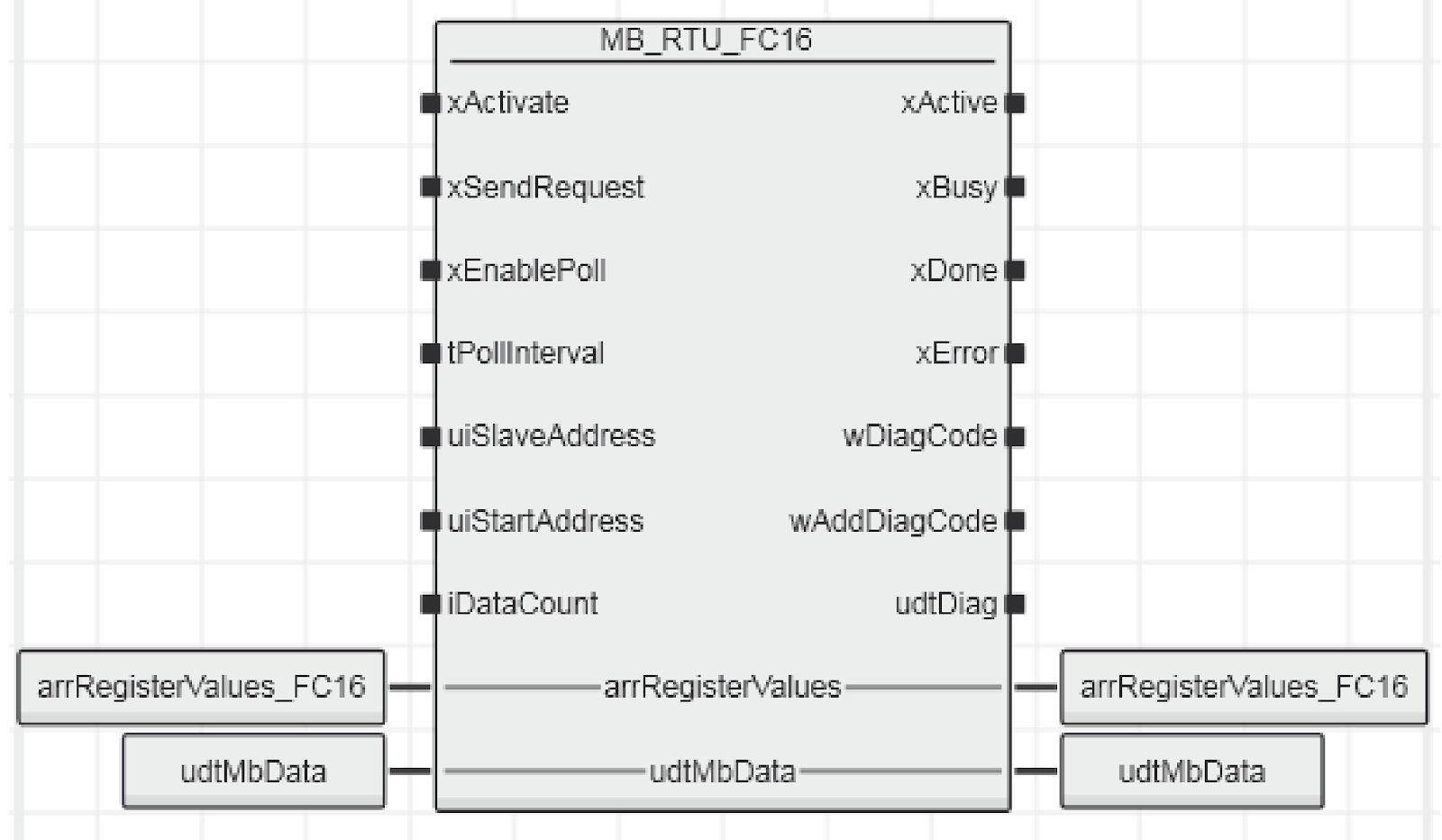
MB_RTU_FC16
This Function Block writes data to the Multiple Holding Register of Modbus.
VAR_INPUT
| Variable Name | Type | Description |
| xActivate | BOOL | True=Enable FB |
| xSendRequest | BOOL | A rising signal sends a send request to the master blockThe falling signal deletes the current Modbus error and still resets the FB output. |
| xEnablePoll | BOOL | A start-up signal initiates cycle polling. |
| tPollIntervall | TIME | Transmission time interval when xEnablePoll is enabled |
| uiSlaveAddress | UINT | Specifies the Slave ID to be communicated (0 to 255) |
| uiStartAddress | UINT | Specify the starting address for read with Slave |
| iDataCount | INT | Specify the number of devices to read in Slave (1-123) |
VAR_OUTPUT
| Variable Name | Type | Description |
| xActive | BOOL | True=FB enabled. |
| xBusy | BOOL | True=FB is running |
| xDone | BOOL | True=Request is sent and response from the slave is successfully received |
| xError | BOOL | True=FB with error, see wDiagCode and wAddDiagCode for details |
| wDiagCode | WORD | FB Diagnostic Information |
| wAddDiagCode | WORD | FB Diagnostic Information 2 |
| udtDiag | MB_UDT_RTU_FC_DIAG | Structure variable with internal variables for diagnostics |
VAR_INOUT
| Variable Name | Type | Description |
| arrReadData | arrModbus2_W_1_123 | Array of 123 words in length, variable for writing to the Multiple Holding Register |
| udtMBData | udtModbus2_Data | Interface to communicate with MB_AXL_SE_RS485_Master |
MB_AXL_SE_RS485_Master
This Function Block is used to implement the Modbus Master for the specified module (AXL SE RS485 in this case).
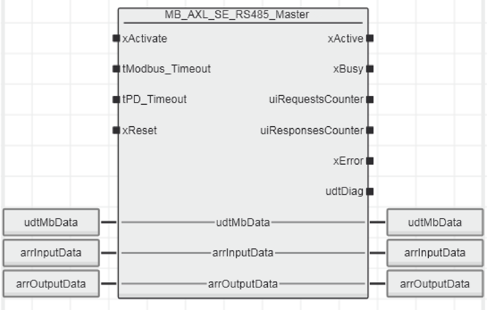
VAR_INPUT
| Variable Name | Type | Description |
| xActivate | BOOL | True=Enable Function Block |
| tModbus_Timeout | TIME | Communication Timeout time between Modbus RTU and SlaveDefault=TIME#5s |
| tPD_Timeout | TIME | Process Data communication timeout time between PLC and module (AXL SE RS485 in this case) |
| xReset | BOOL | True=Reset FB (note that the internal FC Blocks are reset as well) |
VAR_OUTPUT
| Variable Name | Type | Description |
| xActive | BOOL | True=FB enabled |
| xBusy | BOOL | True=FB is running |
| uiRequestsCounter | UINT | Number of requests sent |
| uiResponsesCounter | UINT | Number of incoming requests |
| udtDiag | MB_UDT_AXL_SE_RS485_DIAG_MASTER | Structure of diagnostic information |
VAR_INOUT
| Variable Name | Type | Description |
| udtMBData | udtModbus2_Data | Interface for MB_AXL_SE_RS485_Master to communicate with other MB_RTU_FCXX Block |
| arrInputData | MB2_AXL_RSUNI2_ARR_B_0_19 | Process Input Data for AXL SE RS485 module |
| arrOutputData | MB2_AXL_RSUNI2_ARR_B_0_19 | Process Output Data of AXL SE RS485 module |
Implementation
Schneider Side
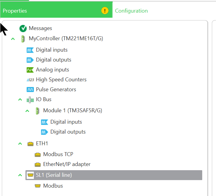
Modbus RTU Slave Configuration
Launch EcoStruxure Machine Expert Basic, open Configuration>SL1 and set the serial communication Port.
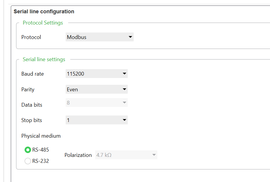
Serial line configuration
Set the Protocol to Modbus, and set the communication speed, etc.
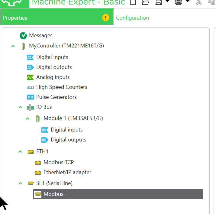
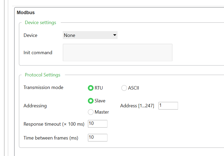
Modbus Configuration
Next, we want to set up the TM221 as a Modbus Slave, so open SL1>Modbus.
Set the Tranmission Mode to RTU, select Slave for Addressing, and set the Address.
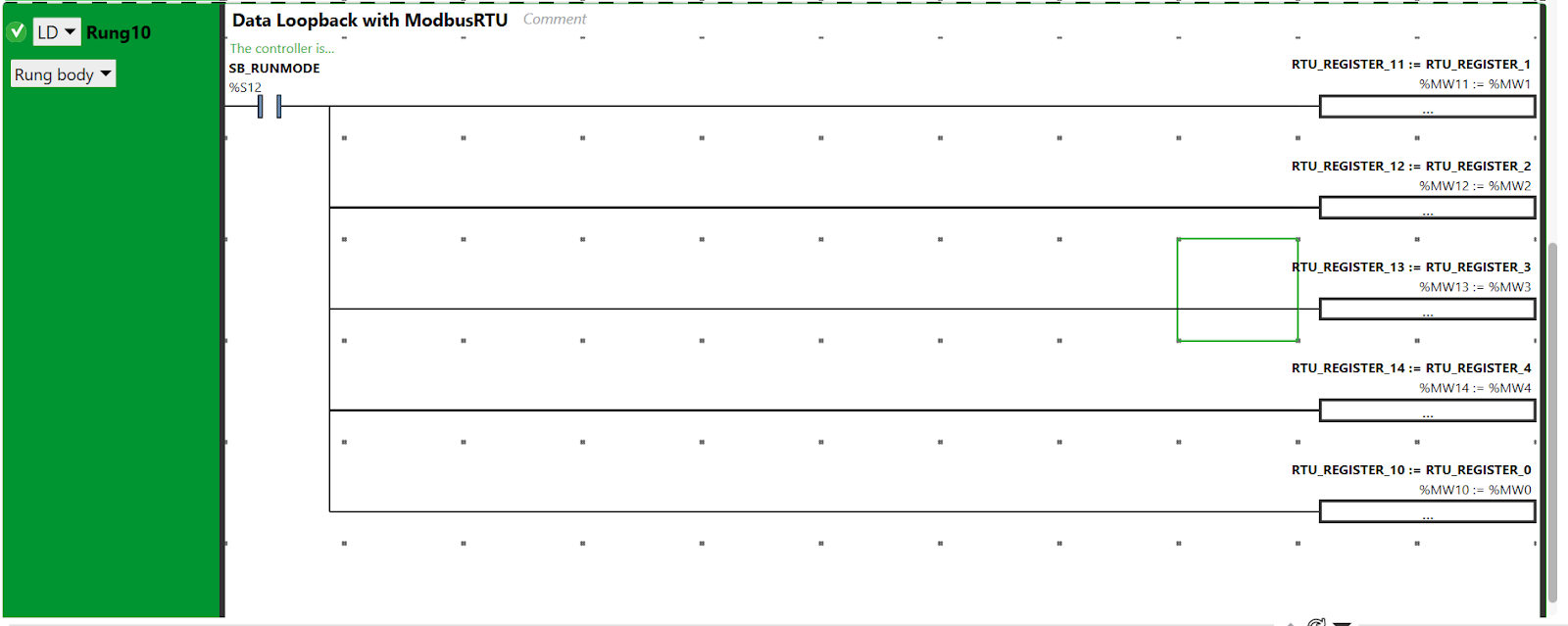
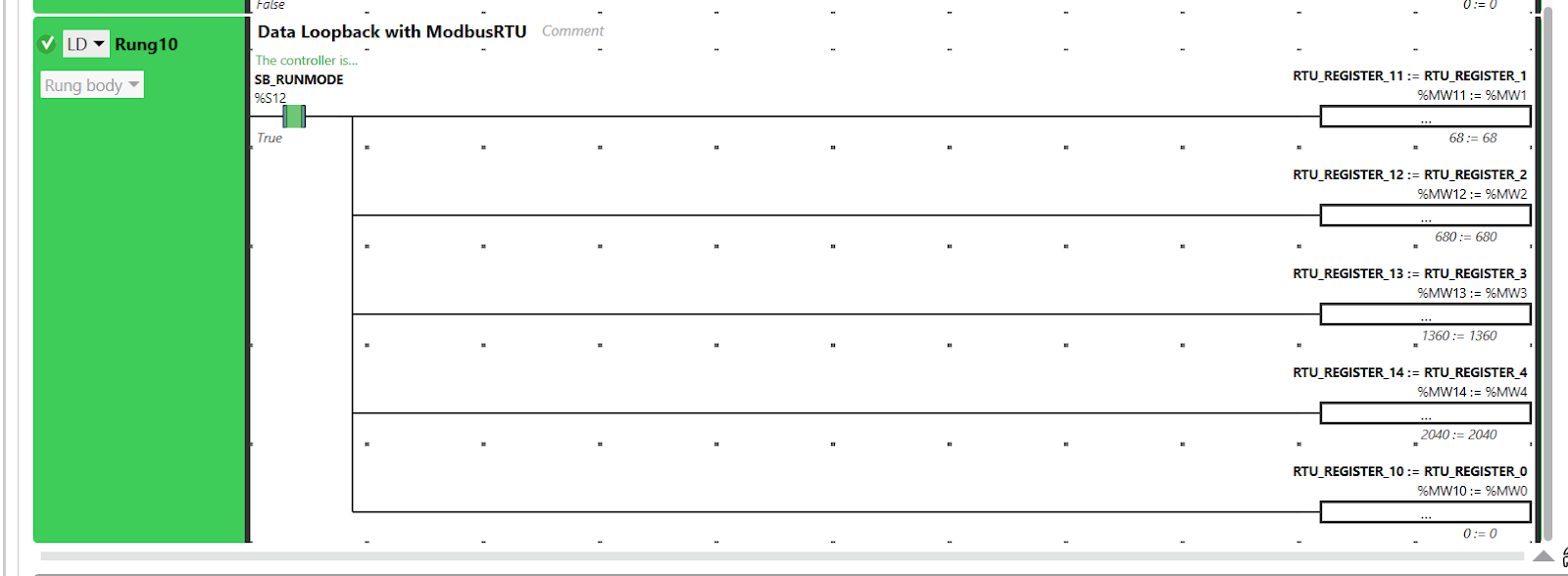
Program
The next step is to create a verification program, a Loop-Back program that feeds back the data received from the Modbus RTU Master.
PLCNEXT Side
Import Library
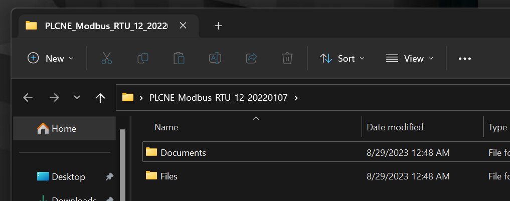
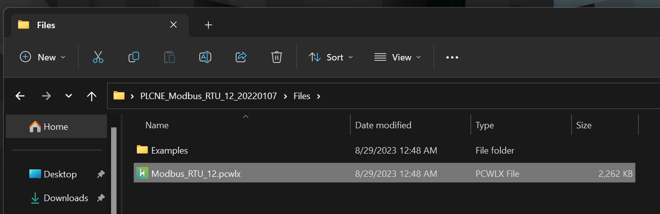
Unzip the library you just downloaded from the PLCNEXT Store, and inside you will find a Documents and Files folder, where Documents is the library manual and Files contains the library itself and examples of its use.
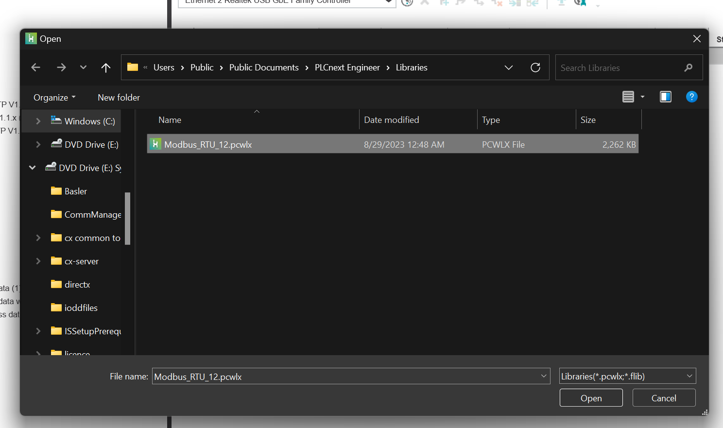
The main body of the library is a PCWLX File, and the File should be duplicated to the following Path.
C:\Users\Public\Documents\PLCnext Engineer\Libraries
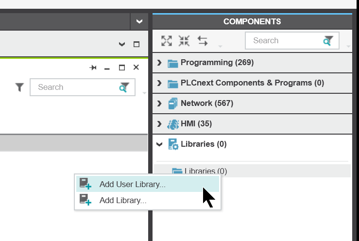
Start PLCNEXT Engineering and add libraries by going to COMPONENTS>Right click>Add User Library.
Open a PCWLX File that you just copied.
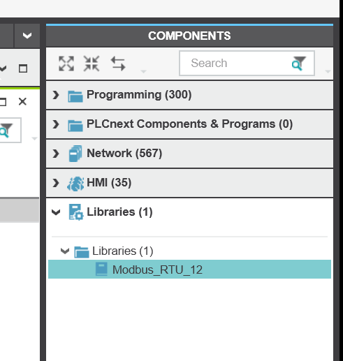
Done!Modbus_RTU library has been added to the project.
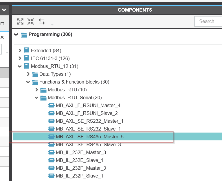
A Modbus_RTU Folder has also been added to Programming, which contains the PLCNEXT serial communication library.
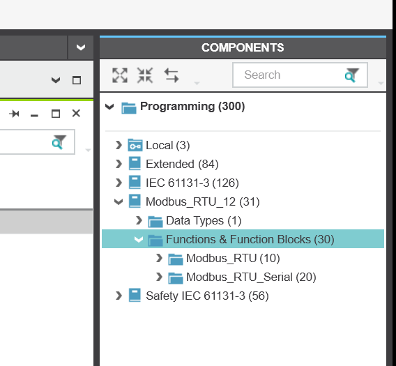
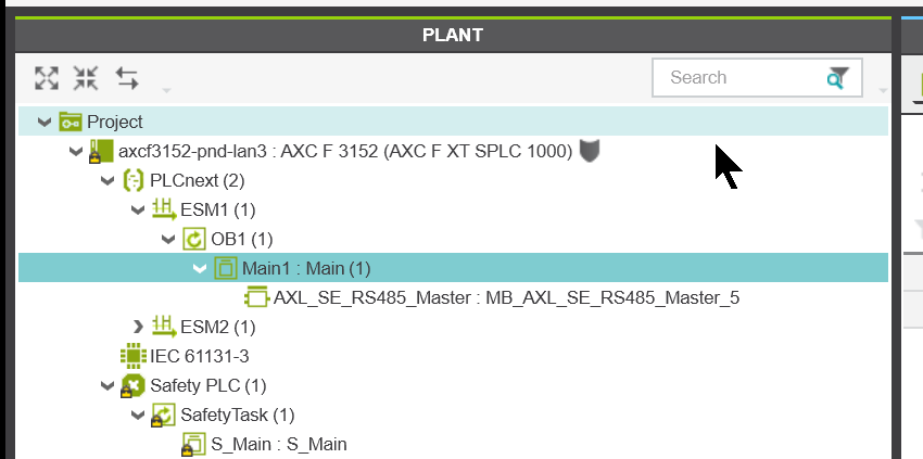
In this case, we will use MB_AXL_SE_RS485_Master since we will be launching Modbus RTU Master from the Smart Elements RS485 module.
Add Module
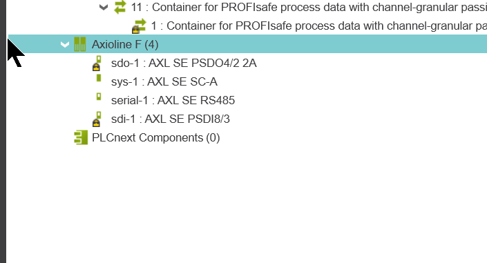
Double-click Axioline F to add the AXL SE RS485 module to the project.
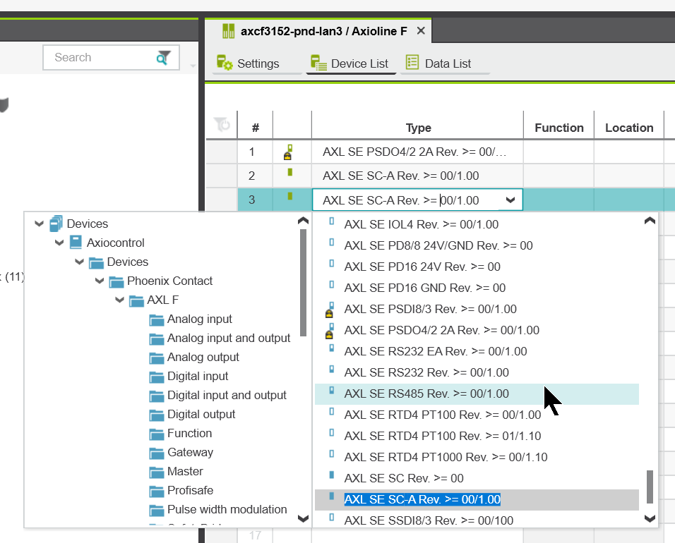
The Device List screen appears.
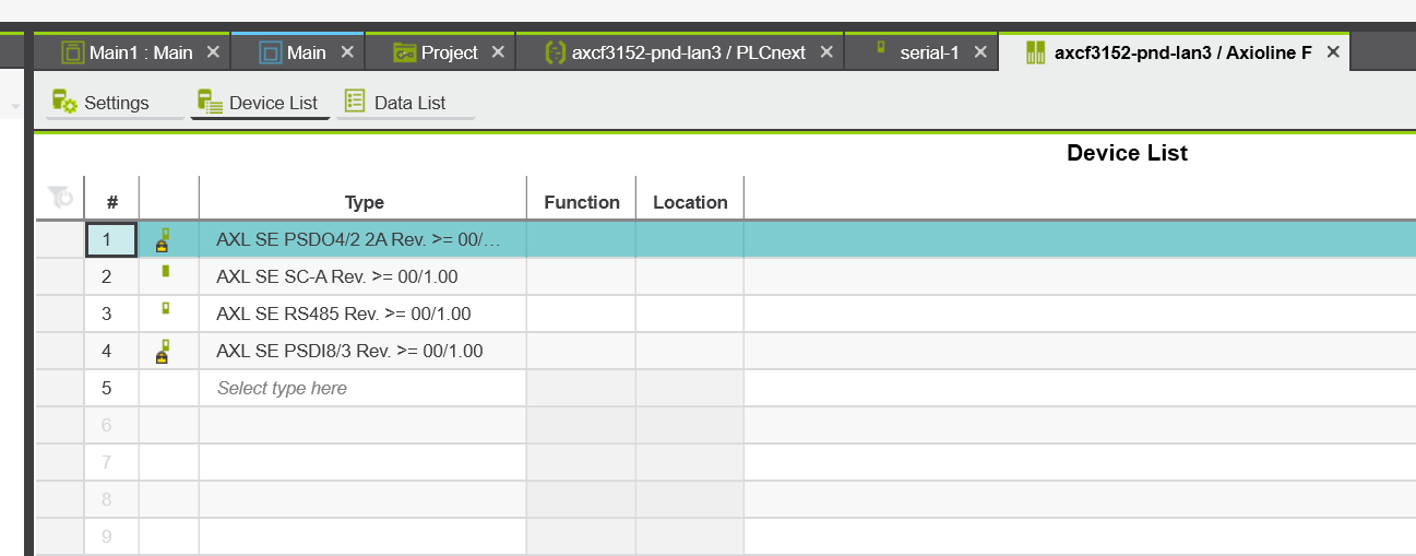
This time, since AXL SE RS485 is installed in Slot 3, click on #3 Type Field and select >AXL SE RS485.
Done!
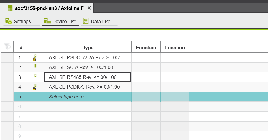
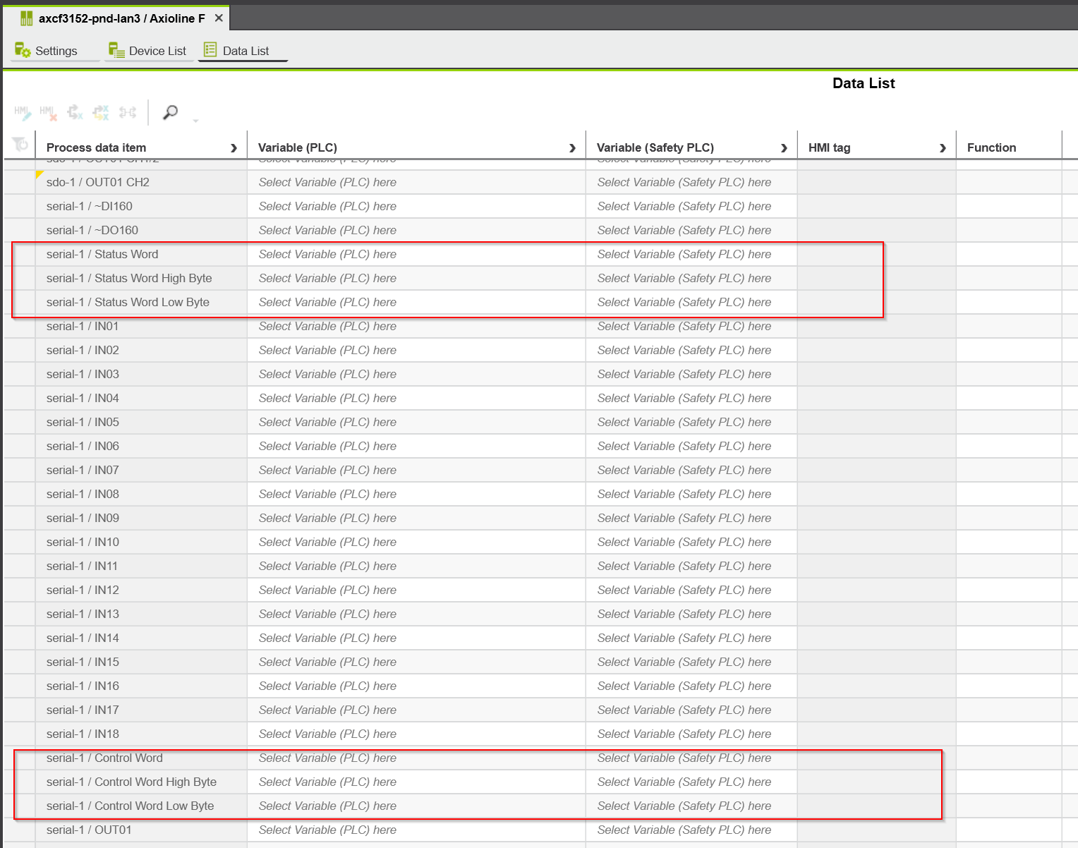
The Data List also automatically declared the relevant variables for the AXL SE RS485 module.
Settings
The next step is to configure the module settings for AXL SE RS485.
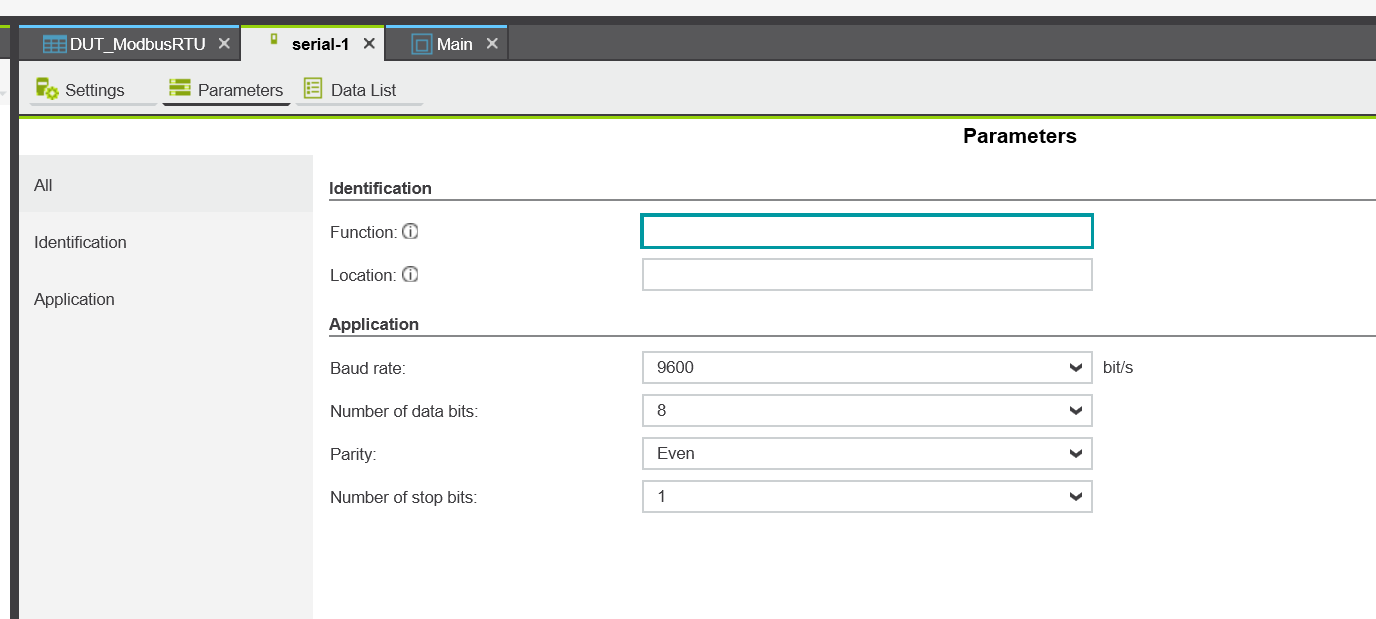
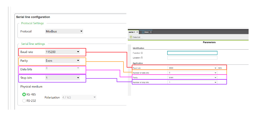
Let’s set the communication parameters of the AXL SE RS485 to match the Modbus RTU Slave on the Schneider PLC side.
Data Types
DUT_ModbusRTU
DUT_ModbusRTU is a Data Type definition Sheet for organizing the structures used in this article.
DUT_MB_RTU_MASTER
This structure collectively defines the INPUT/OUTPUT/INOUT parameters used for the MB_AXL_SE_RS485_Master Function Block.
| DUT_MB_RTU_MASTER : STRUCT //Inputs xActivate : BOOL; xReset : BOOL; xMode : BOOL; tModbus_Timeout : TIME; tPD_Timeout : TIME; //Output xActive : BOOL; xBusy : BOOL; uiRequestsCounter : UINT; uiResponsesCounter : UINT; xError : BOOL; //InOut udtDiag : MB_UDT_AXL_SE_RS485_DIAG_MASTER; END_STRUCT |
DUT_MB_RTU_FC16
This structure collectively defines the INPUT/OUTPUT/INOUT parameters used for the MB_RTU_FC16 Function Block.
| DUT_MB_RTU_FC16 : STRUCT //Inputs xActivate : BOOL; xSendRequest : BOOL; xEnablePoll : BOOL; tPollInterval : TIME; uiSlaveAddress : UINT; uiStartAddress : UINT; iDataCount : INT; //Outputs xActive : BOOL; xBusy : BOOL; xDone : BOOL; xError : BOOL; wDiagCode : WORD; wAddDiagCode : WORD; udtDiag : MB_UDT_RTU_FC_DIAG; //InOut arrRegisterValues : arrModbus2_W_1_123; END_STRUCT; |
DUT_MB_RTU_FC4
This structure collectively defines the INPUT/OUTPUT/INOUT parameters used for the MB_RTU_FC4 Function Block.
| DUT_MB_RTU_FC4 : STRUCT //Inputs xActivate : BOOL; xSendRequest : BOOL; xEnablePoll : BOOL; tPollInterval : TIME; uiSlaveAddress : UINT; uiStartAddress : UINT; iDataCount : INT; //Outputs xActive : BOOL; xBusy : BOOL; xDone : BOOL; xError : BOOL; wDiagCode : WORD; wAddDiagCode : WORD; udtDiag : MB_UDT_RTU_FC_DIAG; //InOut arrRegisterValues : arrModbus2_W_1_125; END_STRUCT |
DUT_MB_Modbus_RTU
This structure is a compilation of those defined earlier.
| DUT_MB_Modbus_RTU : STRUCT iState : INT; udtMBData : udtModbus2_Data; udtMB_AXL_SE_RS485_Master : DUT_MB_RTU_MASTER; udtMB_RTU_FC16 : DUT_MB_RTU_FC16; udtMB_RTU_FC4 : DUT_MB_RTU_FC4; END_STRUCT; |
Program
The next step is to create a program.
Flow

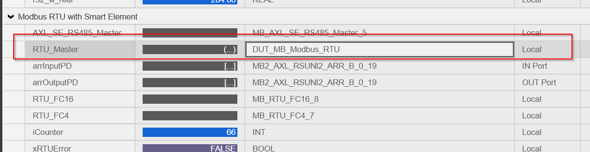
VAR
Define the variables to be used this time in the Main program.
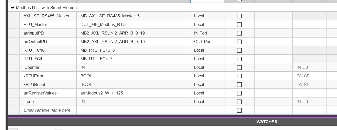
| AXL_SE_RS485_Master | Instance to launch Modbus RTU Master on AXL SE RS485 |
| RTU_Master | The structure defined earlier, containing variables to be assigned to the parameters of the Function Block |
| arrInputPD | Process Input Data for AXL SE RS485 module |
| arrOutputPD | Process Output Data of AXL SE RS485 module |
| RTU_FC16 | Instance to issue Modbus RTU Function Code 16 |
| RTU_FC4 | Instance to issue Modbus RTU Function Code 4 |
| iCounter | Data of PLCNEXT side write to Schneider PLC |
| xRTUError | Flag of Modbus RTU communication error occurrence |
| xRTUReset | Device to reset Modbus RTU program |
| arrRegisterValues | Buffer to store data read from the Schneider PLC |
| iLoop | Counter for FOR Loop |
Code
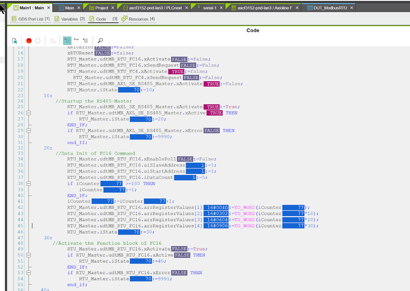
Here is the program.
| i16_w_Int:=i16_w_Int+1;r32_w_real:=r32_w_real+0.01;if r32_w_real>=10000.0 THEN r32_r_Real:=0.0;end_if; case RTU_Master.iState OF 0: //Parameters Init RTU_Master.udtMB_AXL_SE_RS485_Master.tModbus_Timeout:=T#5s; RTU_Master.udtMB_AXL_SE_RS485_Master.tPD_Timeout:=T#2s; xRTUError:=False; xRTUReset:=false; RTU_Master.udtMB_RTU_FC16.xActivate:=false; RTU_Master.udtMB_RTU_FC16.xSendRequest:=False; RTU_Master.udtMB_RTU_FC4.xActivate:=false; RTU_Master.udtMB_RTU_FC4.xSendRequest:=False; RTU_Master.udtMB_AXL_SE_RS485_Master.xActivate:=False; if not RTU_Master.udtMB_AXL_SE_RS485_Master.xBusy THEN RTU_Master.iState:=10; end_if; 10: //Startup the RS485-Master RTU_Master.udtMB_AXL_SE_RS485_Master.xActivate:=True; if RTU_Master.udtMB_AXL_SE_RS485_Master.xActive THEN RTU_Master.iState:=20; END_IF; if RTU_Master.udtMB_AXL_SE_RS485_Master.xError THEN RTU_Master.iState:=9990; end_If; 20: //Data Init of FC16 Command RTU_Master.udtMB_RTU_FC16.xEnablePoll:=False; RTU_Master.udtMB_RTU_FC16.uiSlaveAddress:=1; RTU_Master.udtMB_RTU_FC16.uiStartAddress:=1; RTU_Master.udtMB_RTU_FC16.iDataCount:=5; if iCounter >=100 THEN iCounter:=1; END_IF; iCounter:=iCounter+1; RTU_Master.udtMB_RTU_FC16.arrRegisterValues[1]:=TO_WORD(iCounter); RTU_Master.udtMB_RTU_FC16.arrRegisterValues[2]:=TO_WORD(iCounter*10); RTU_Master.udtMB_RTU_FC16.arrRegisterValues[3]:=TO_WORD(iCounter*20); RTU_Master.udtMB_RTU_FC16.arrRegisterValues[4]:=TO_WORD(iCounter*30); RTU_Master.iState:=30; 30: //Activate the Function block of FC16 RTU_Master.udtMB_RTU_FC16.xActivate:=True; if RTU_Master.udtMB_RTU_FC16.xActive THEN RTU_Master.iState:=40; END_IF; if RTU_Master.udtMB_RTU_FC16.xError THEN RTU_Master.iState:=9991; end_if; 40: //Send the request to slave with Function Code 16 RTU_Master.udtMB_RTU_FC16.xSendRequest:=True; if RTU_Master.udtMB_RTU_FC16.xDone THEN RTU_Master.udtMB_RTU_FC16.xSendRequest:=False; RTU_Master.iState:=45; end_if; if RTU_Master.udtMB_RTU_FC16.xError THEN RTU_Master.iState:=9992; end_if; 45: //Data Init of FC4 Command and Reset FC16 Command RTU_Master.udtMB_RTU_FC16.xActivate:=False; RTU_Master.udtMB_RTU_FC4.xEnablePoll:=False; RTU_Master.udtMB_RTU_FC4.uiSlaveAddress:=1; RTU_Master.udtMB_RTU_FC4.uiStartAddress:=11; RTU_Master.udtMB_RTU_FC4.iDataCount:=5; RTU_Master.iState:=50; 50: //Check if the FB is reset if RTU_Master.udtMB_RTU_FC16.xActive=False THEN RTU_Master.iState:=60; end_If; 60: //Activate the Function block of FC4 RTU_Master.udtMB_RTU_FC4.xActivate:=True; for iLoop :=1 to 125 DO arrRegisterValues[iLoop]:=0; end_for; if RTU_Master.udtMB_RTU_FC4.xActive THEN RTU_Master.iState:=70; END_IF; if RTU_Master.udtMB_RTU_FC4.xError THEN RTU_Master.iState:=9993; end_if; 70: //Send the request to slave with Function Code 4 RTU_Master.udtMB_RTU_FC4.xSendRequest:=True; if RTU_Master.udtMB_RTU_FC4.xDone THEN RTU_Master.udtMB_RTU_FC4.xSendRequest:=False; RTU_Master.udtMB_RTU_FC4.xActivate:=False; arrRegisterValues:=RTU_Master.udtMB_RTU_FC4.arrRegisterValues; RTU_Master.iState:=80; end_if; if RTU_Master.udtMB_RTU_FC4.xError THEN RTU_Master.iState:=9994; end_if; 80: //Check if the FB is reset if RTU_Master.udtMB_RTU_FC4.xActive=False THEN RTU_Master.iState:=20; end_If; 9991,9992,9993,9994: //Error xRTUError:=True; if xRTUReset THEN RTU_Master.iState:=0; end_if; end_case; //Function Block for smart elements AXL_SE_RS485_Master( xActivate:=RTU_Master.udtMB_AXL_SE_RS485_Master.xActivate ,tModbus_Timeout:=RTU_Master.udtMB_AXL_SE_RS485_Master.tModbus_Timeout ,tPD_Timeout:=RTU_Master.udtMB_AXL_SE_RS485_Master.tPD_Timeout ,xReset:=RTU_Master.udtMB_AXL_SE_RS485_Master.xReset ,xActive=>RTU_Master.udtMB_AXL_SE_RS485_Master.xActive ,xBusy=>RTU_Master.udtMB_AXL_SE_RS485_Master.xBusy ,uiRequestsCounter=>RTU_Master.udtMB_AXL_SE_RS485_Master.uiRequestsCounter ,uiResponsesCounter=>RTU_Master.udtMB_AXL_SE_RS485_Master.uiResponsesCounter ,xError=>RTU_Master.udtMB_AXL_SE_RS485_Master.xError ,udtDiag=>RTU_Master.udtMB_AXL_SE_RS485_Master.udtDiag ,udtMbData:=RTU_Master.udtMBData ,arrInputData:=arrInputPD ,arrOutputData:=arrOutputPD ) ;//Function Block of FC16 RTU_FC16( xActivate:=RTU_Master.udtMB_RTU_FC16.xActivate ,xSendRequest:=RTU_Master.udtMB_RTU_FC16.xSendRequest ,xEnablePoll:=RTU_Master.udtMB_RTU_FC16.xEnablePoll ,uiSlaveAddress:=RTU_Master.udtMB_RTU_FC16.uiSlaveAddress ,uiStartAddress:=RTU_Master.udtMB_RTU_FC16.uiStartAddress ,iDataCount:=RTU_Master.udtMB_RTU_FC16.iDataCount ,xActive=>RTU_Master.udtMB_RTU_FC16.xActive ,xBusy=>RTU_Master.udtMB_RTU_FC16.xBusy ,xDone=>RTU_Master.udtMB_RTU_FC16.xDone ,xError=>RTU_Master.udtMB_RTU_FC16.xError ,wDiagCode=>RTU_Master.udtMB_RTU_FC16.wDiagCode ,wAddDiagCode=>RTU_Master.udtMB_RTU_FC16.wAddDiagCode ,arrRegisterValues:=RTU_Master.udtMB_RTU_FC16.arrRegisterValues ,udtMbData:=RTU_Master.udtMBData ) ; //Function Block of FC4 RTU_FC4( xActivate:=RTU_Master.udtMB_RTU_FC4.xActivate ,xSendRequest:=RTU_Master.udtMB_RTU_FC4.xSendRequest ,xEnablePoll:=RTU_Master.udtMB_RTU_FC4.xEnablePoll ,uiSlaveAddress:=RTU_Master.udtMB_RTU_FC4.uiSlaveAddress ,uiStartAddress:=RTU_Master.udtMB_RTU_FC4.uiStartAddress ,iDataCount:=RTU_Master.udtMB_RTU_FC4.iDataCount ,xActive=>RTU_Master.udtMB_RTU_FC4.xActive ,xBusy=>RTU_Master.udtMB_RTU_FC4.xBusy ,xDone=>RTU_Master.udtMB_RTU_FC4.xDone ,xError=>RTU_Master.udtMB_RTU_FC4.xError ,wDiagCode=>RTU_Master.udtMB_RTU_FC4.wDiagCode ,wAddDiagCode=>RTU_Master.udtMB_RTU_FC4.wAddDiagCode ,arrReaddata:=RTU_Master.udtMB_RTU_FC4.arrRegisterValues ,udtMbData:=RTU_Master.udtMBData ) ; |
Mapping
We have just defined IN Port and Out Port variables for arrInputPD and arrOutputPD, but we need to assign these variables to Process Data in the AXL SE RS485 module.
Open the Main program.
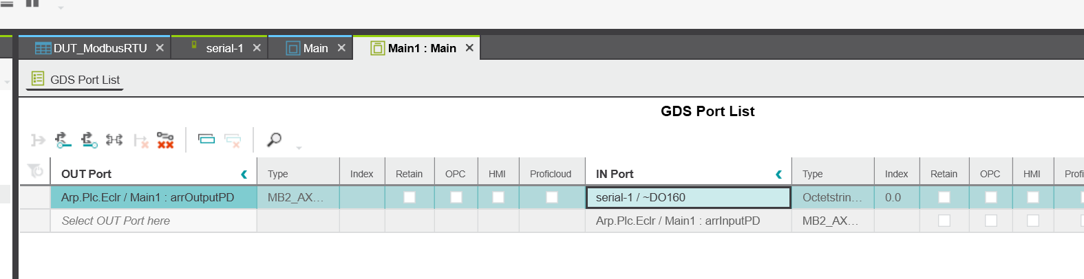
The GDS Port List screen of the Main program is now displayed.
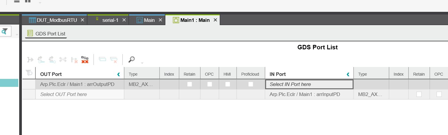
IN Port
Select the IN Port field and set Axioline F>Serial-1/~DO160 in order to link the IN Port to the Process Output Data of the AXL SE RS485.
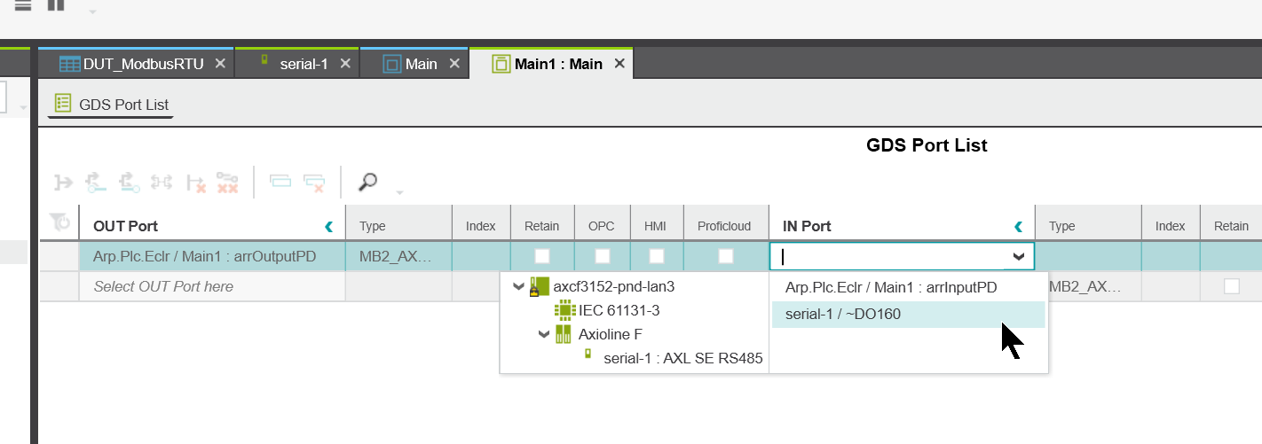
Done!
OUT Port
Select the OUT Port field and set Axioline F>Serial-1/~DO160 in order to link the OUT Port to the Process Output Data of the AXL SE RS485.
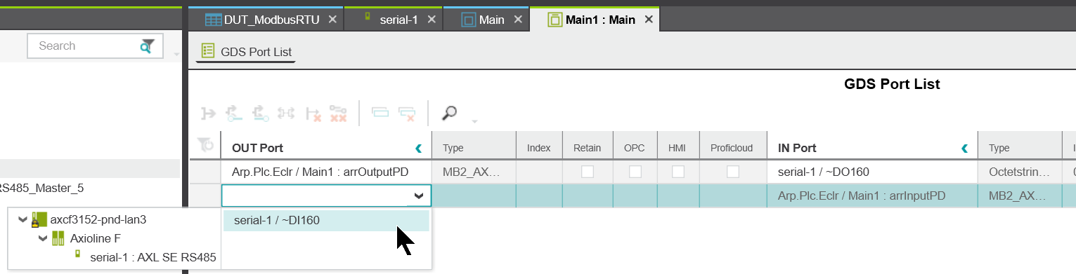
Done!
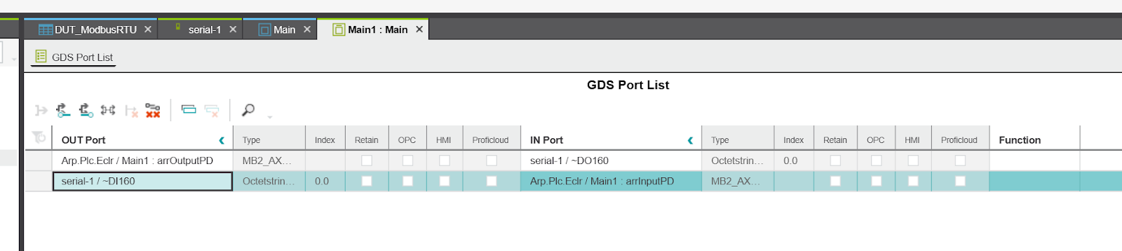
Structure
Here is the actual program structure.
Result
Done!The program is running without errors.
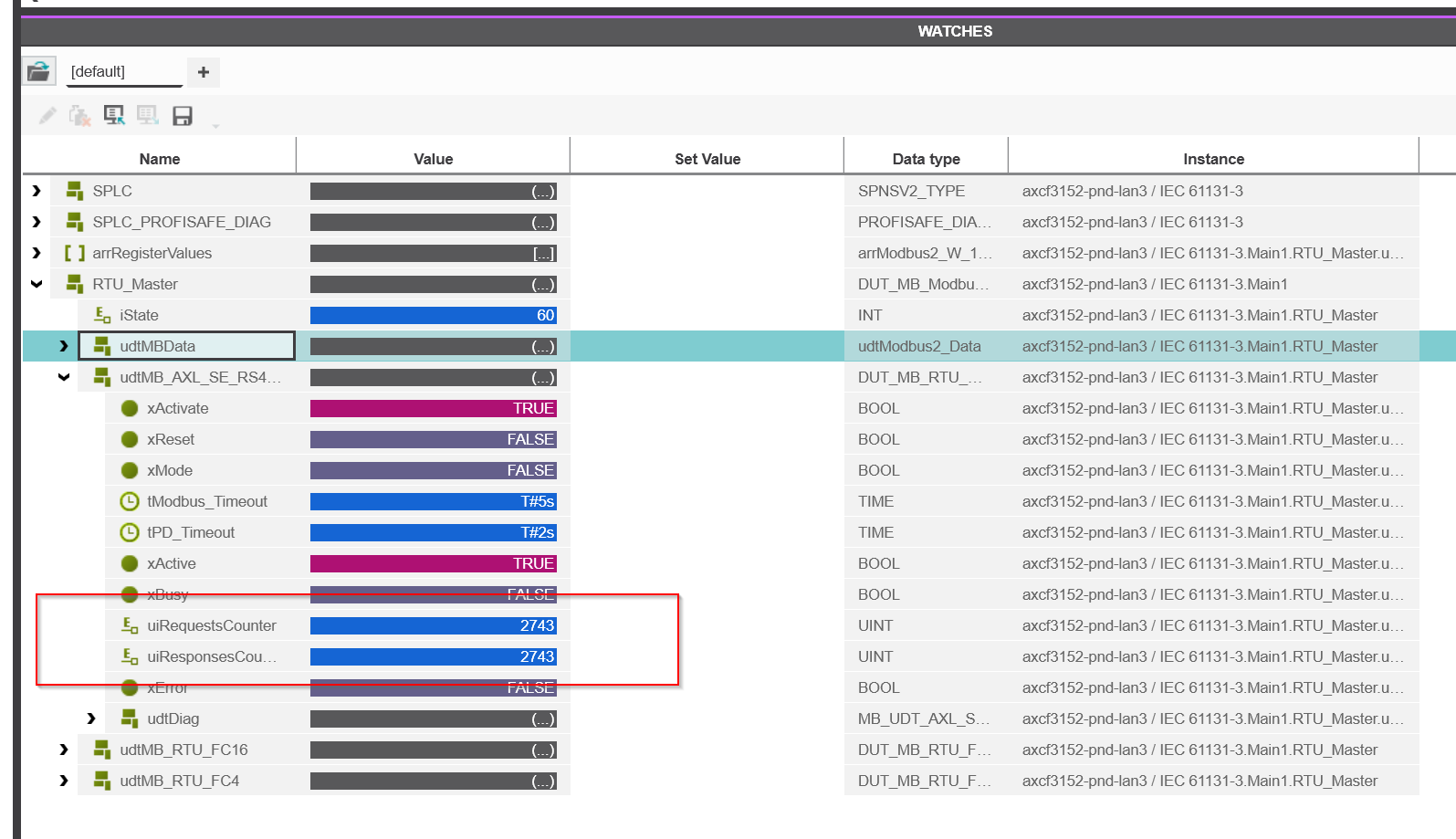
Monitors RTU_Master structure variables.
The Request Counter and the Response Counter are also added, indicating that they are communicating with Slave.
Schneider TM221 received the data Loop Backed by TM221.
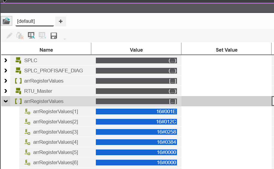
Likewise, we were able to receive PLCNEXT data from Schneider TM221.
You can actually check the LED status of the AXL SE RS485 when it is working properly from this video.
Download
You can download the project from this link.
https://github.com/soup01Threes/PLCNEXT/blob/main/Project-RS485pcwex.pcwex