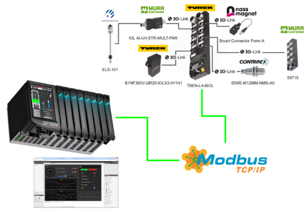
In this article, the Groov view function of the Opto22’s EPIC CPU is used to communicate via Modbus TCP with TURCK’s IO-Link Master, which supports multi-protocols, to display data and diagnostic information for each port.
Now let’s get started!
Groov View?
The browser-based Groov View enables the construction of an operator interface for monitoring and managing the system from the device.
Only authorized users can also view the groov View HMI on a computer or mobile device for remote monitoring and control. In addition, the same HMI can be viewed on an HDMI monitor connected to the groov EPIC.
Advantages
Because you develop the interface yourself, the HMI contains just what you need and using Groov View offers the following benefits
- Small. And it is easy to add another indicator or control only when needed.
- Simple. If the interface is used on a computer, a web-enabled TV or a mobile phone, select the gadget to be displayed on each.
- Driver. if required, add data and controls from any manufacturer, e.g. OPC UA or Modbus, and mix them on the same page.
- Security. Authorized users can be given access to only those screens that they should see. For example, an operator may need to control part of a process, while a manager may only need production data.
- Compatibility.Screens created with Groov View can be displayed and operated on Windows PC, Mac and Linux PCs, mobile phones and tablets.
Reference Link
http://soup01.com/en/?s=OPTO22
Groov view
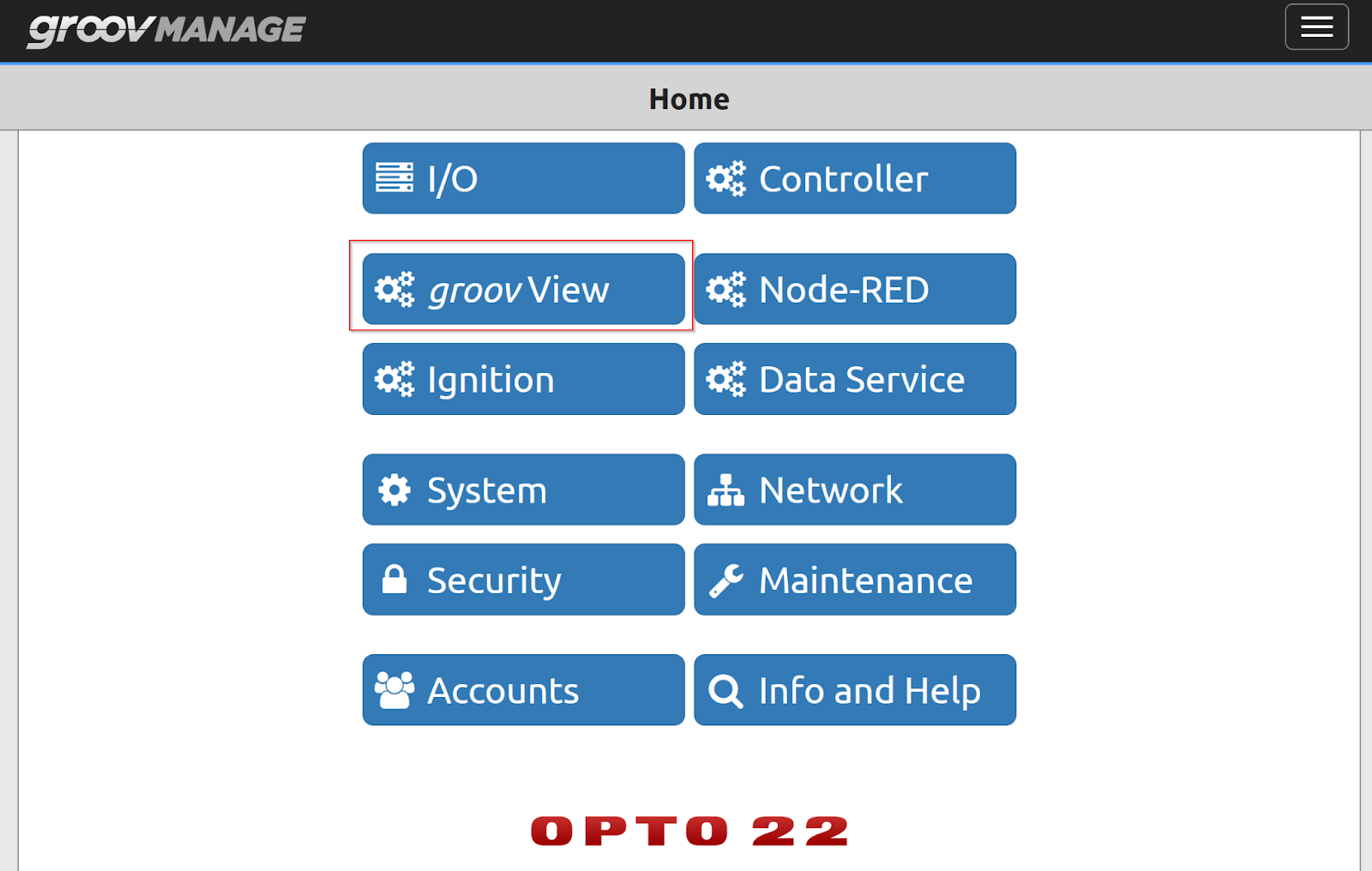
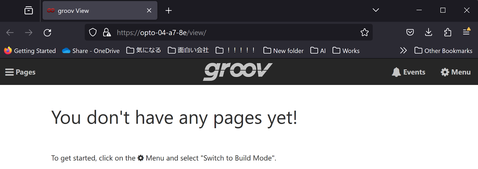
Click on the EPIC PLC’s groovMANAGE screen > GroovView.
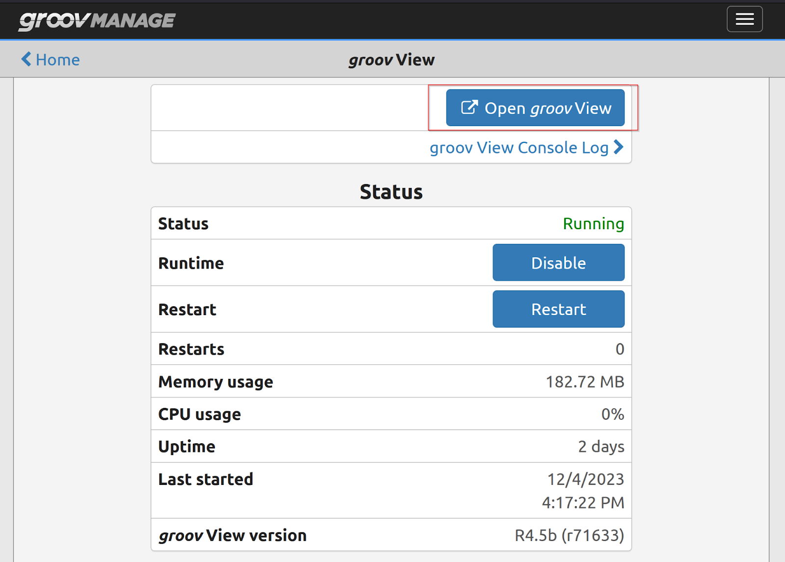
Click on the Open groovView button.
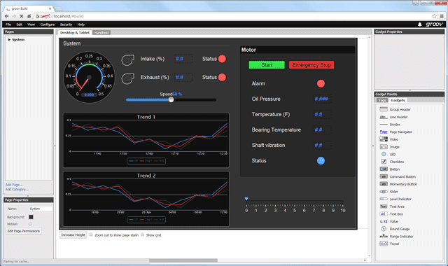
Grrov View画面はまだ作成していませんので、Build Modeに切り替え、画面を作りましょう。
Build Mode
To create a Groov View screen you need to change the Build Mode – click on Menu>Switch to Build mode.
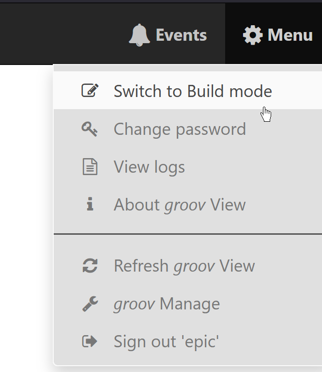
Switched to Build Mode.
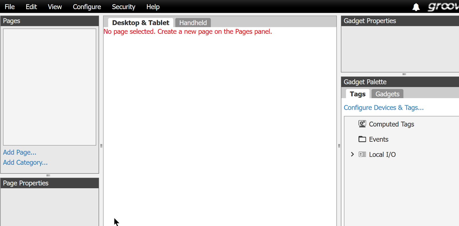
Add Page
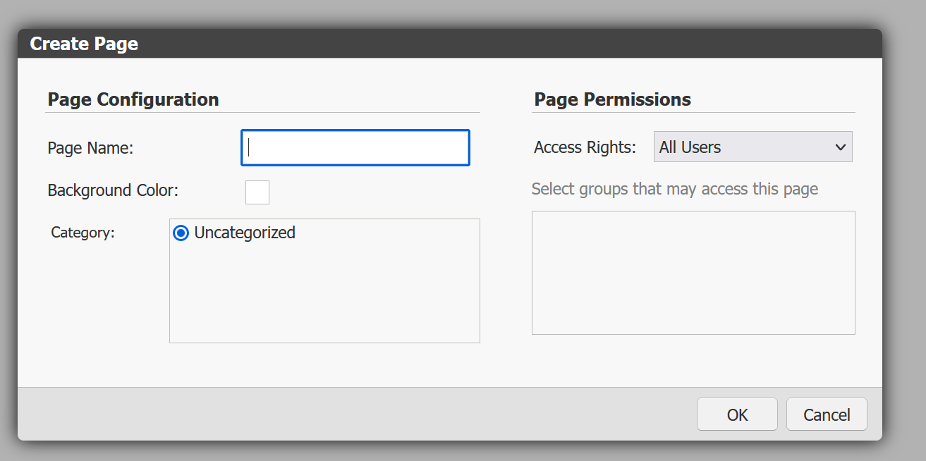
Click on the ‘Add Page’ button from the left to add a new page.
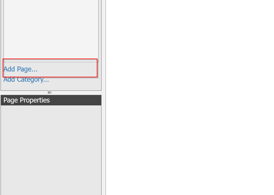
Enter Page Name and confirm with Ok.
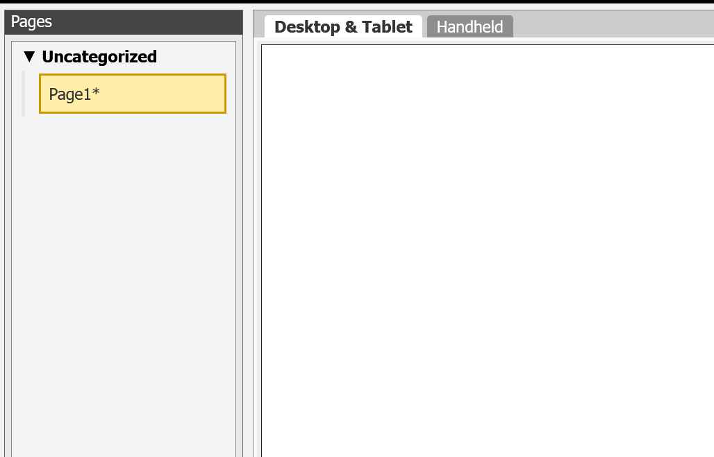
Done!A new screen has been added.
Add New Devices
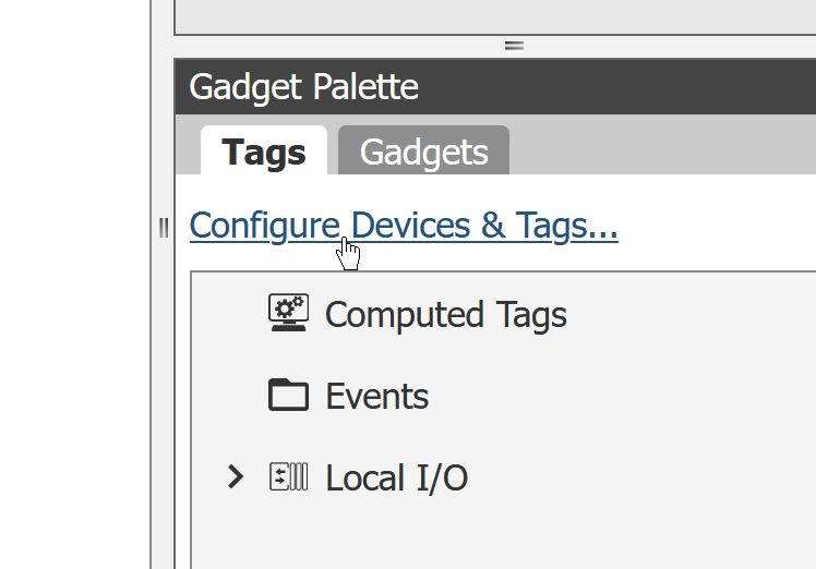
Next, click Gadget Palette>Tags>Configure Devices & Tags to add Tags that communicate with the Groov view.
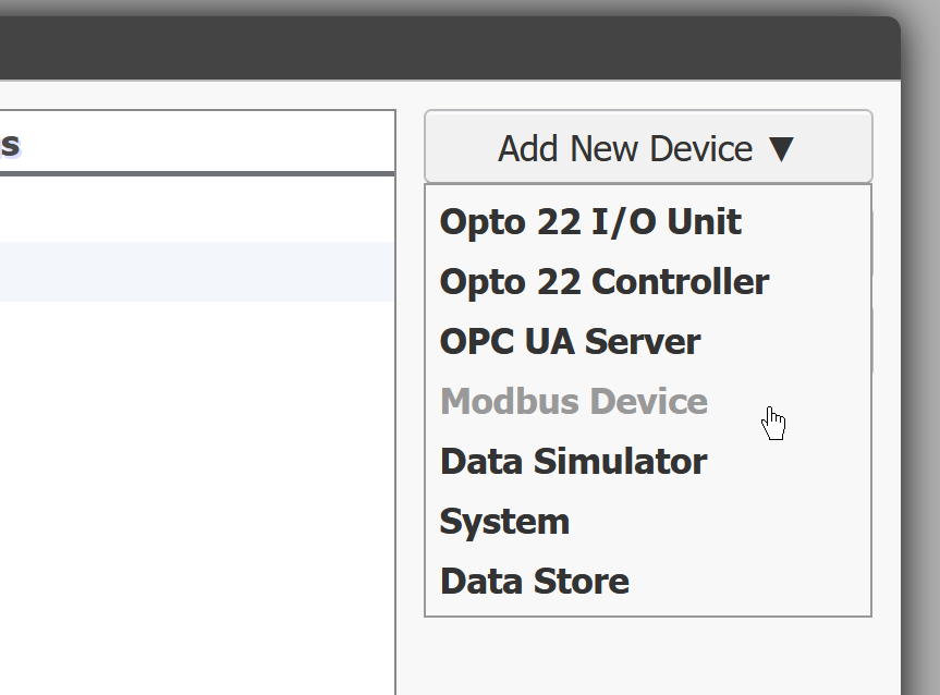
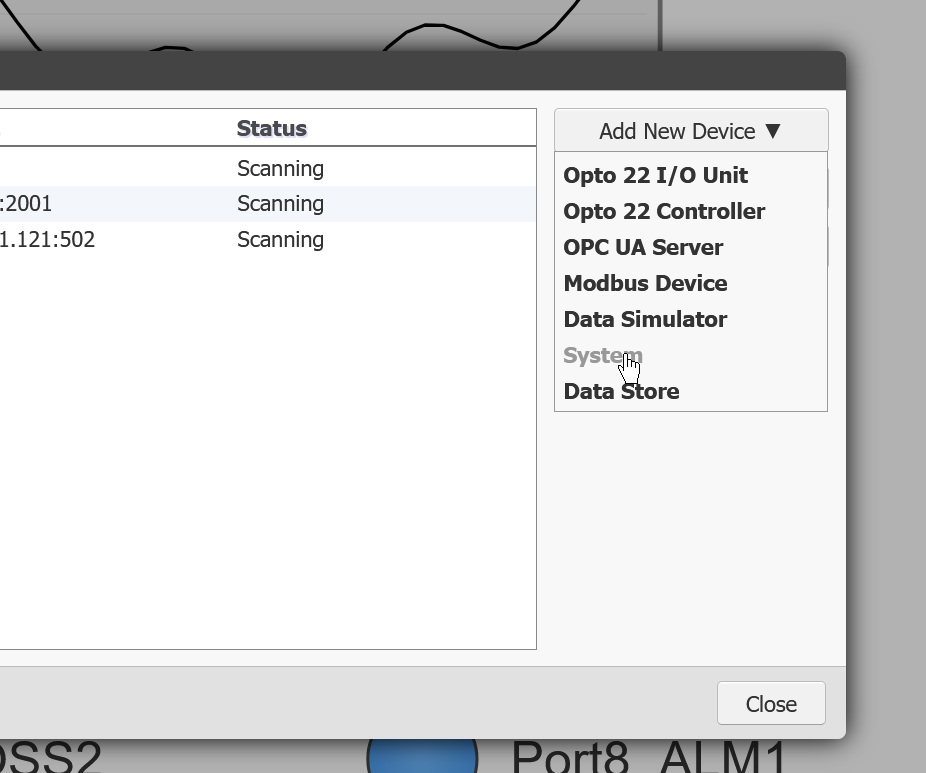
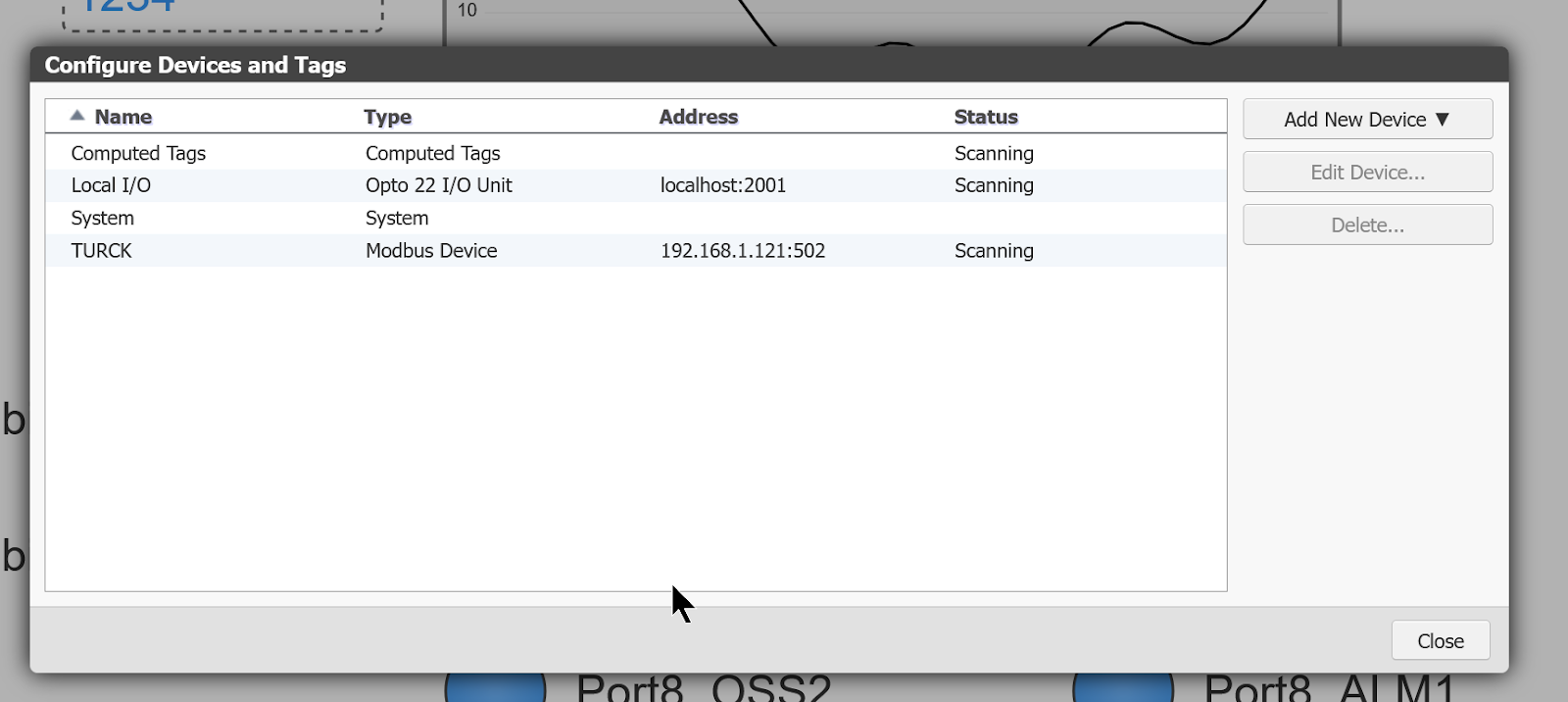
The communication tags setting and confirmation screen is displayed and the ‘Add New Device’ button is clicked.
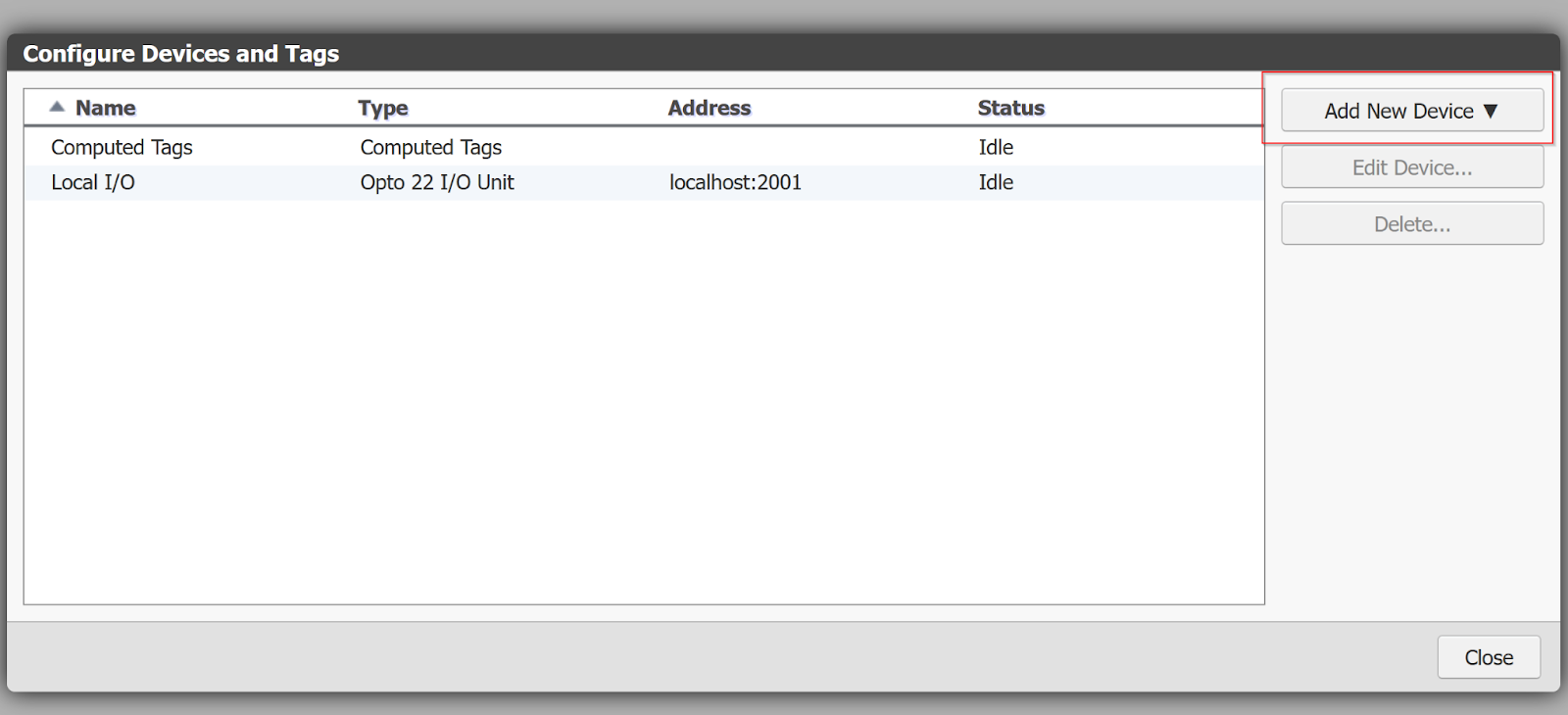
This time, we will connect to the Modbus TCP Server built into the TURCK IO-LINK Master, so select Modbus Device.
The Modbus Device configuration screen appears.
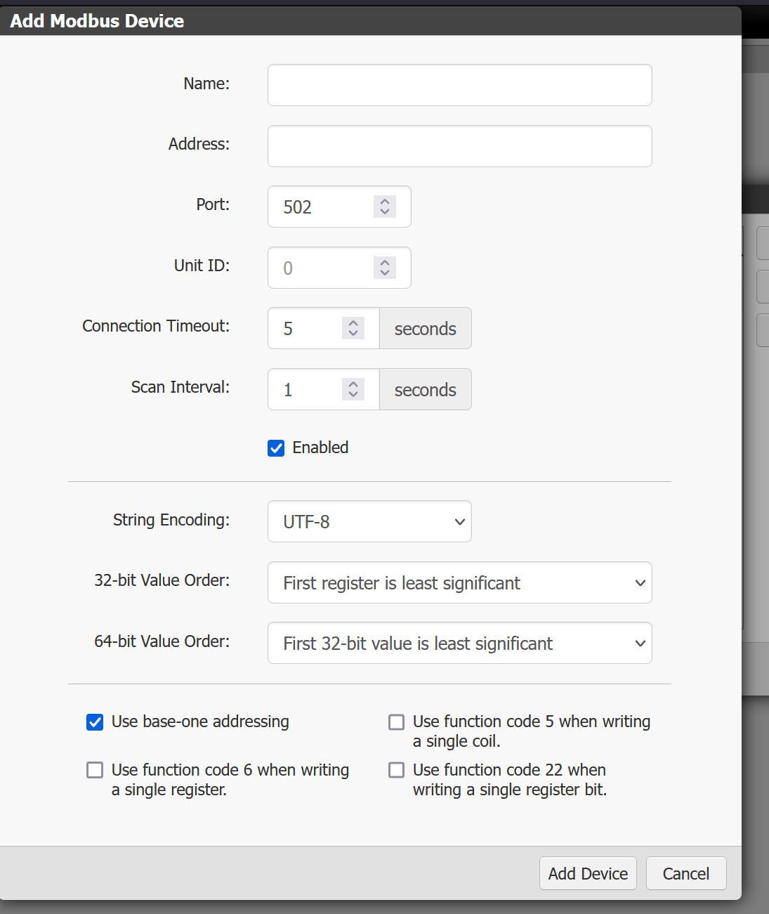
Enter the IP address of the TURCK and the Modbus Default Port 502 and proceed with “Add Devices”.
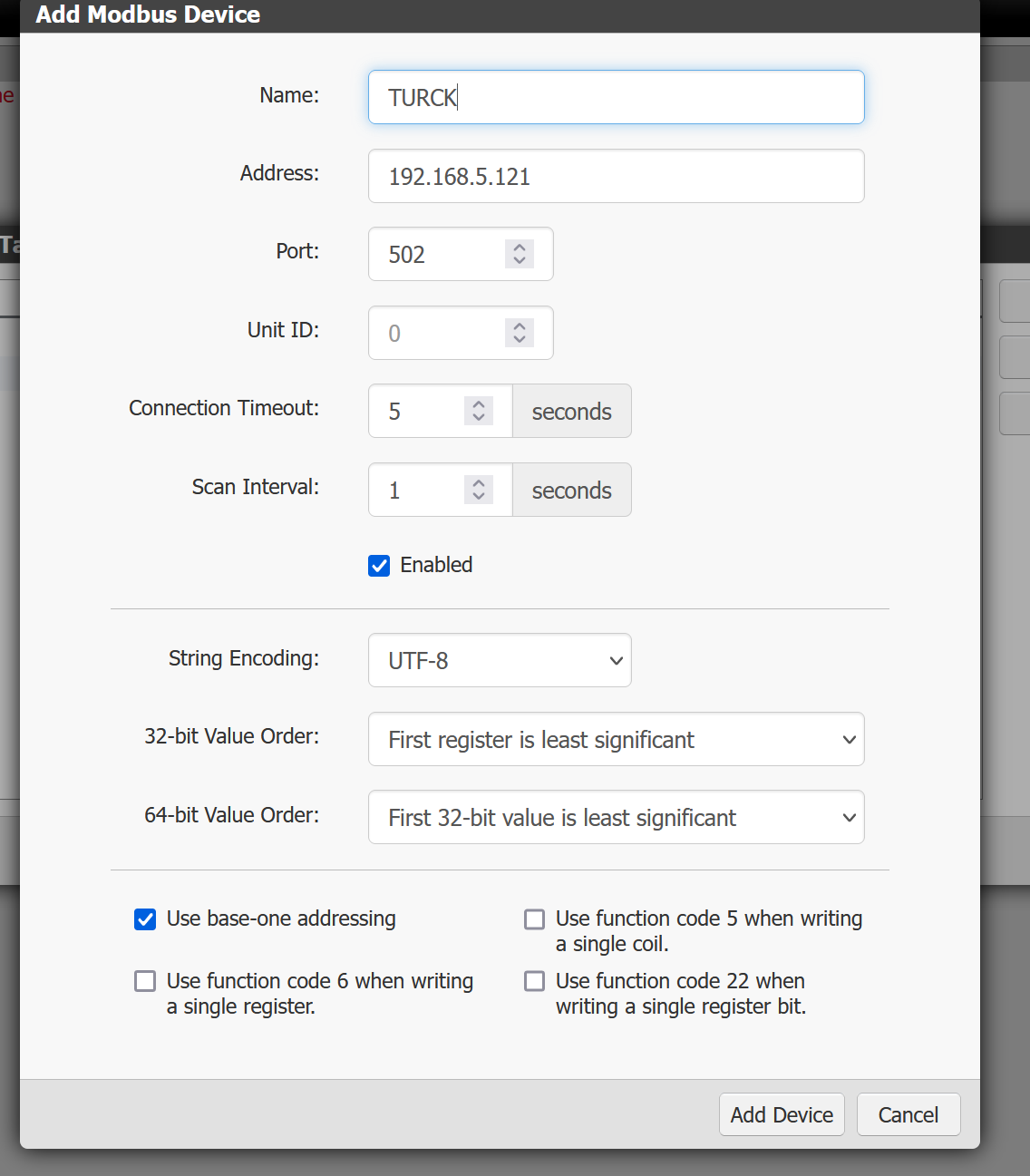
Done!
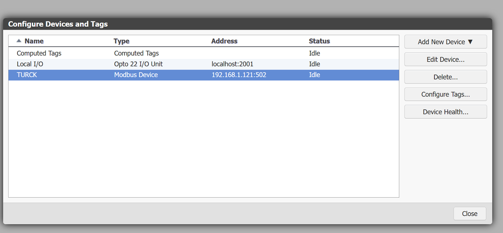
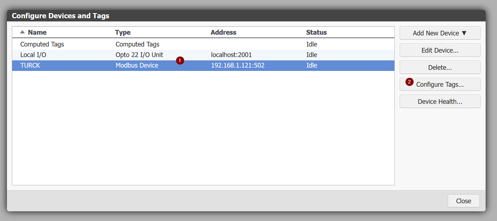
Configure Tags
Next, to define the Tags that communicate with the TURCK device, select TURCK and click >Configure Tags.
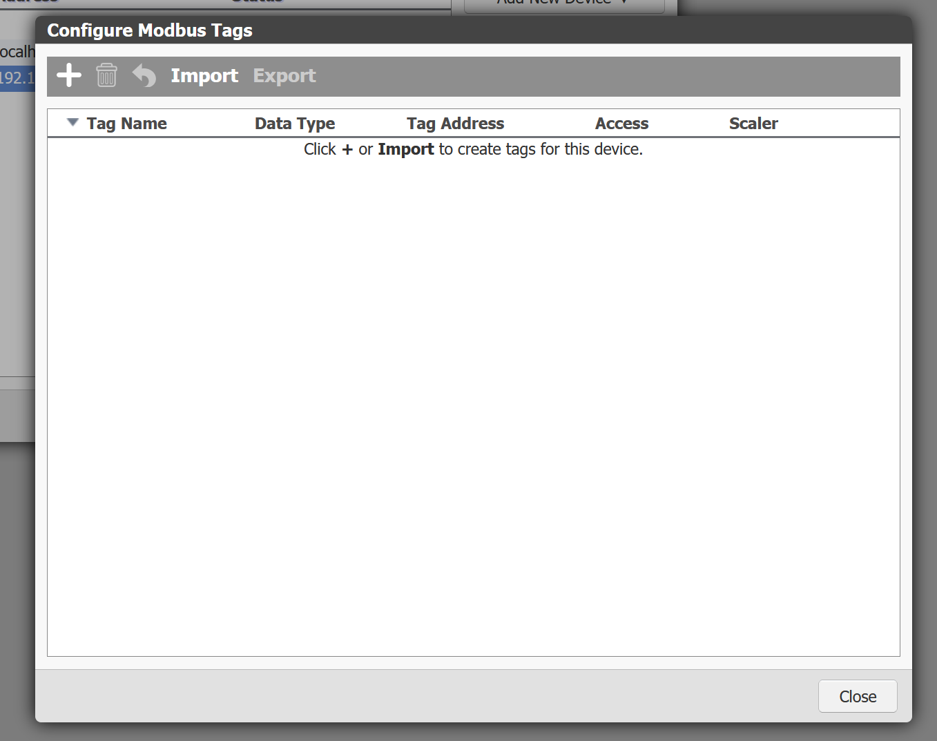
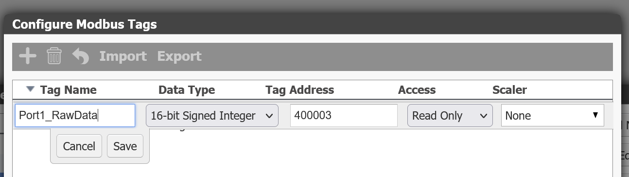
The Modbus Tags definition screen is displayed.
Add a new Tag using the + Add new tags button.
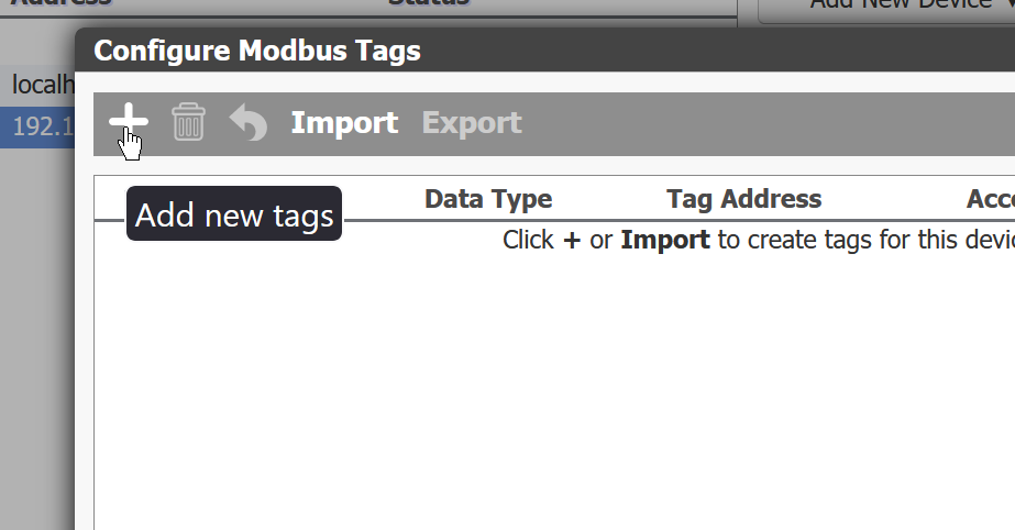
This will set up the Tag.
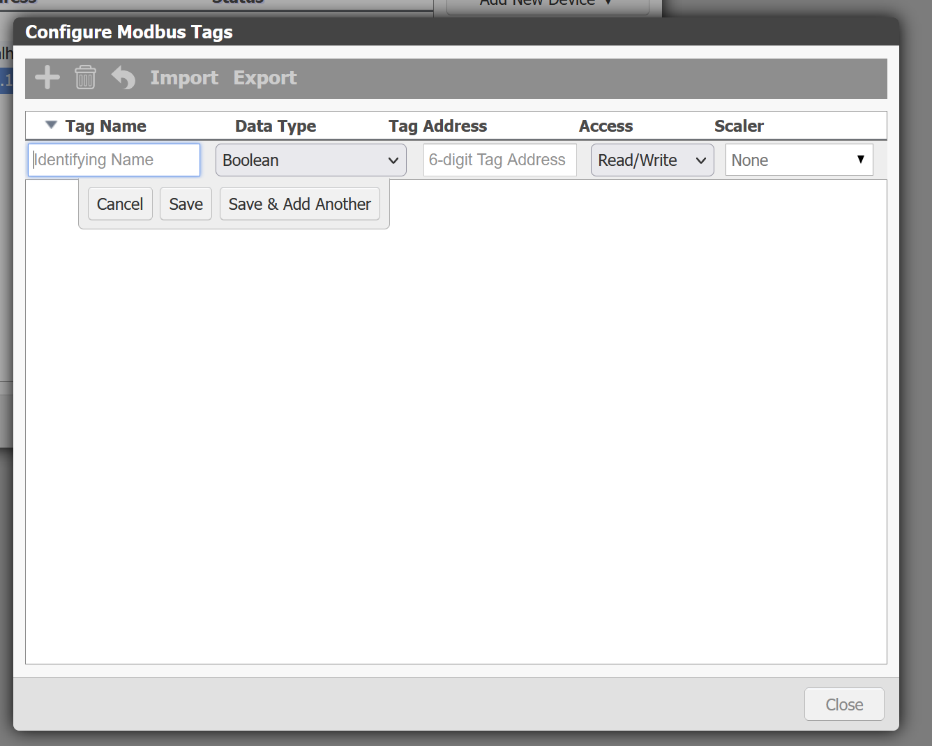
Set the name of the new Tag to be created, the Data Type and Address should be set according to the actual Modbus Register and application to be accessed.
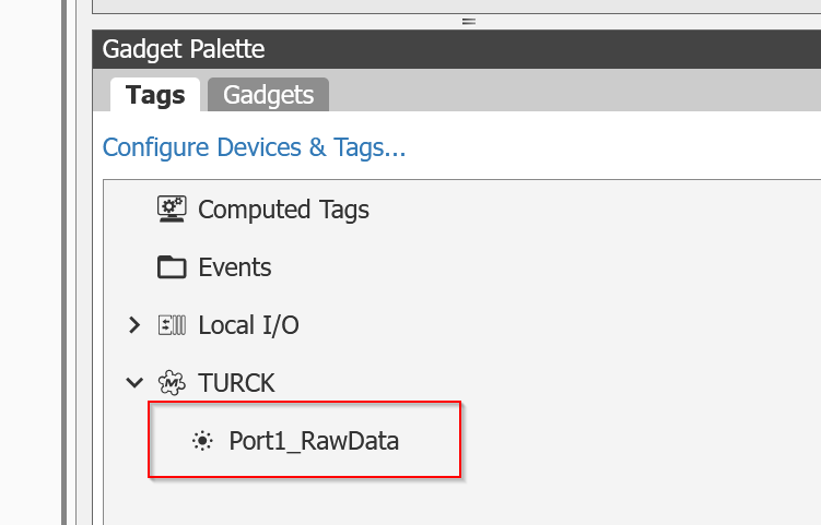
TURC>Port1_RawData has been added.
Add Compoents
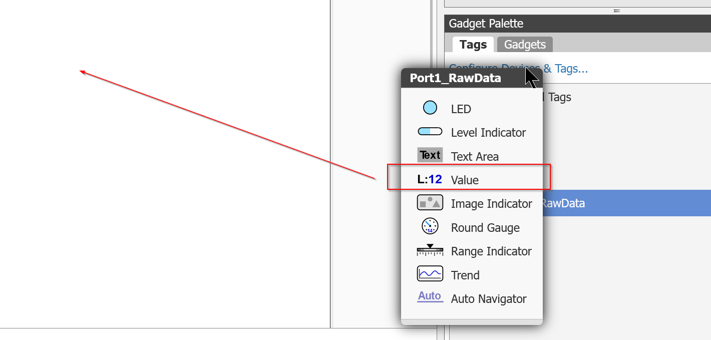
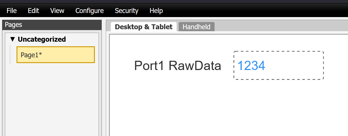
Next, you can click on that Tag and add any number of HMI display components. To start with, you should first add a Valve (numerical display or input).
Done!This was automatically added with the Tag name and Tag value set.
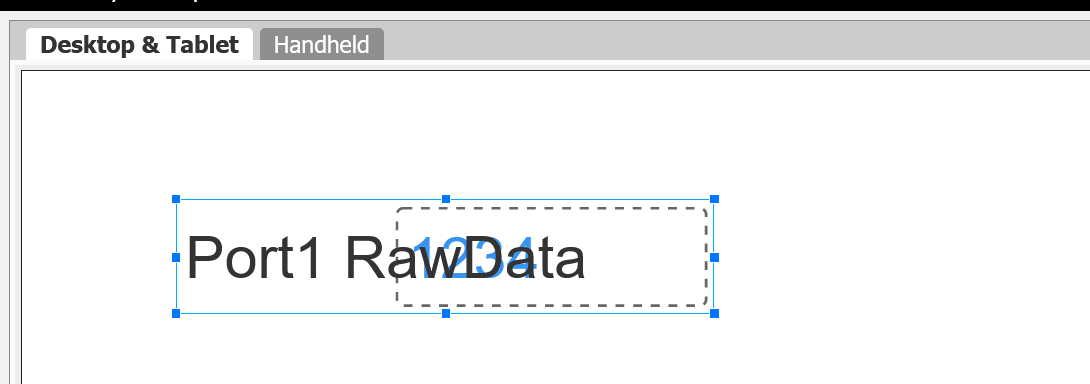
Adjust the text size and other factors to suit the application.
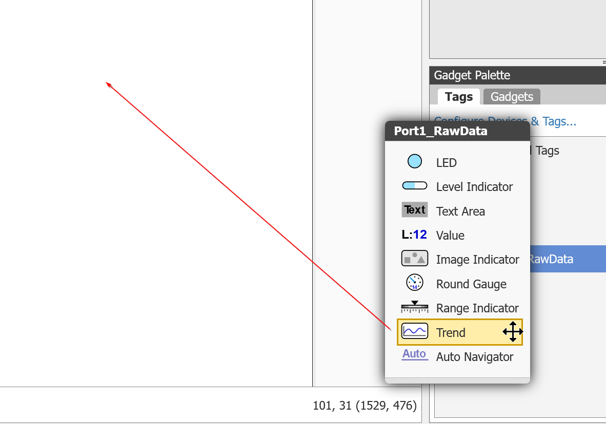
Trend
The next step is to add a trace display.
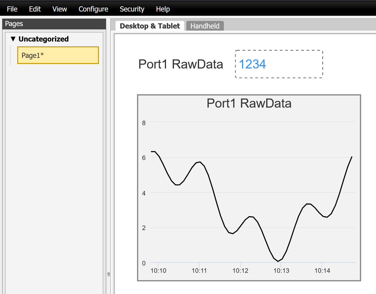
Done!
Save your First View
Once you have created a screen, switch to view mode using File>Save All Changes and Switch to groov View.
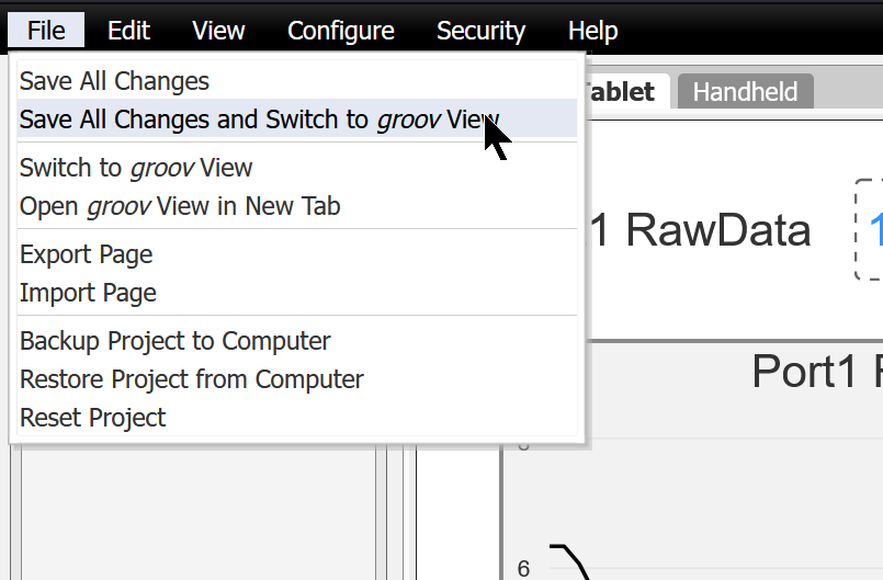
This is the actual data display.
Export
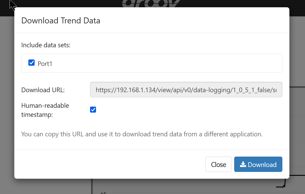
In fact, traces can be displayed and the current values of the Tag can also be checked. The Groov view also has a function for exporting data.
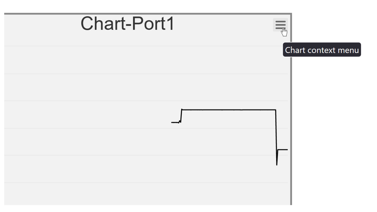
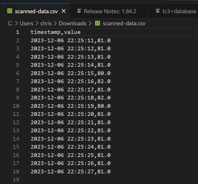
If you select the data you want to export and go to >Download, you can download a File in CSV format.
The File is shown in the diagram below.
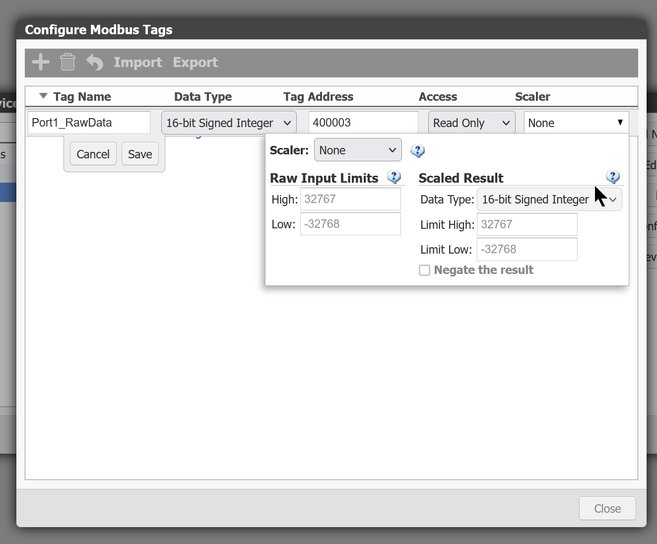
Scaler the data
Groov view can not only read Tag values directly, but can also Scaler them before displaying them. Open the Scaler Menu in the Tags settings screen.
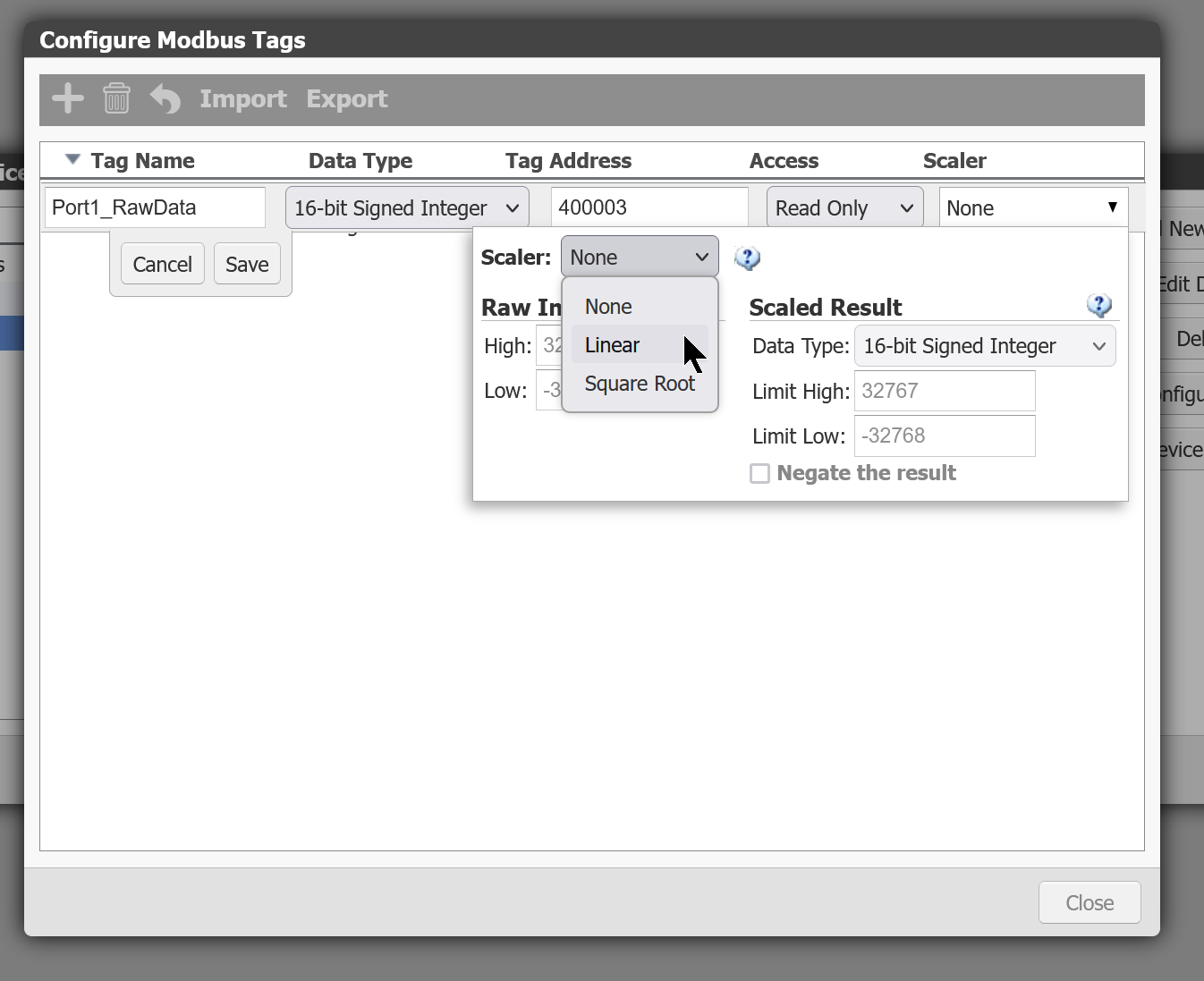
Scaler Mode is set to Linear.
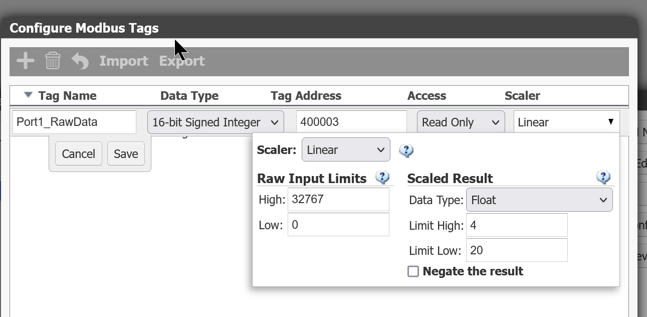
Port1_RawData can be Scaled from 0-32767 to 4-20 by setting Data Type to Float, Low and High from 0 to 32767 and Limit High and Limit Low from 4-20.
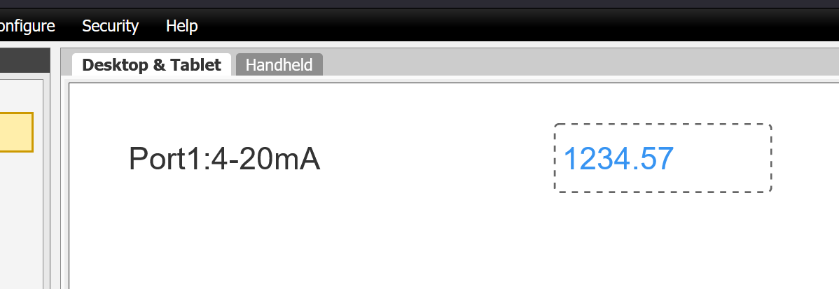
Change Label
The display letter of the Value Object will be the Tag name as it is in Default, but the display letter can also be changed from the Label Field in the Properties screen.
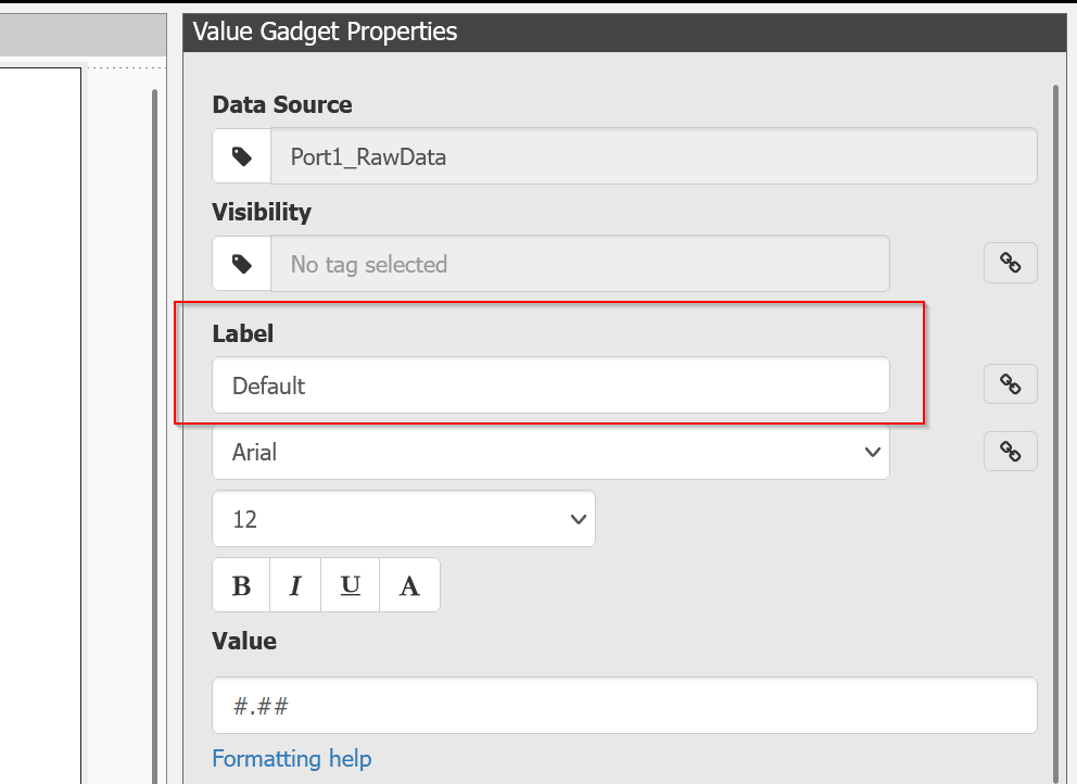
For example, change Label to Port1:4-20mA.
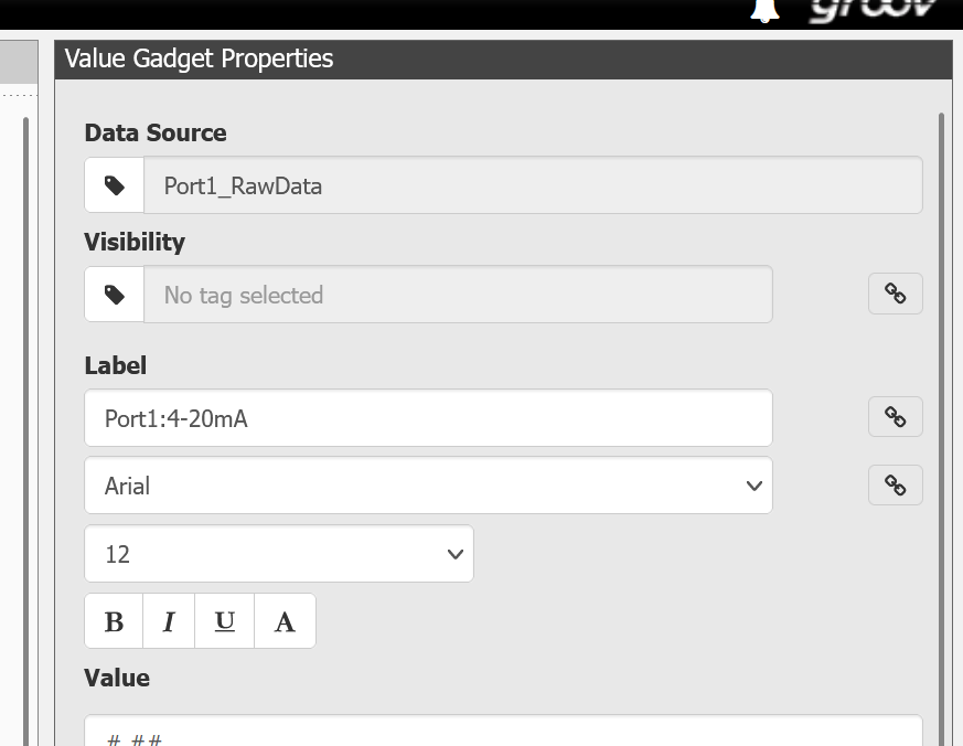
Done!
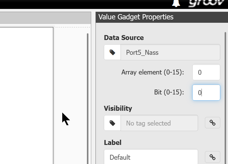
Bit Access
Groov view can also access specific Bits in the Tag, for example, in the example below, the 0th of the Port5_Nass array data, Bit 0.
LED
Now add the LED components.
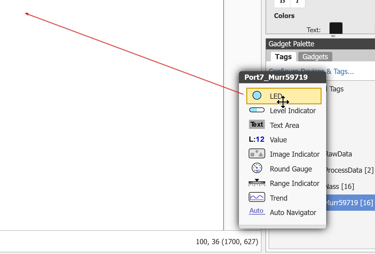
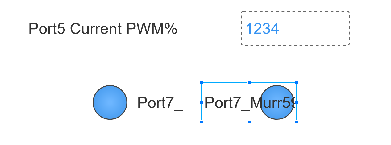
In Default, the text is on the left and the LED picture is on the right.

It can also be changed in the Alignment settings.
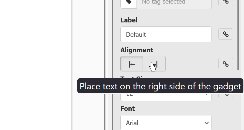
Thus, Port7_Murr59719 has the text on the right and the LED picture on the left.
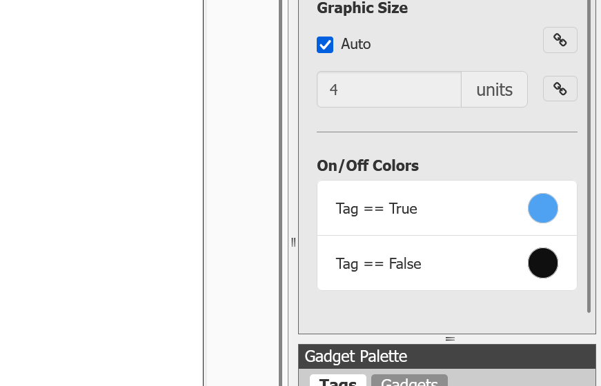
You can also change the colour of the LED ON/OFF – there is an On/Off Colors section in Properties, where you can change the colour to match your application.
Computer Tags
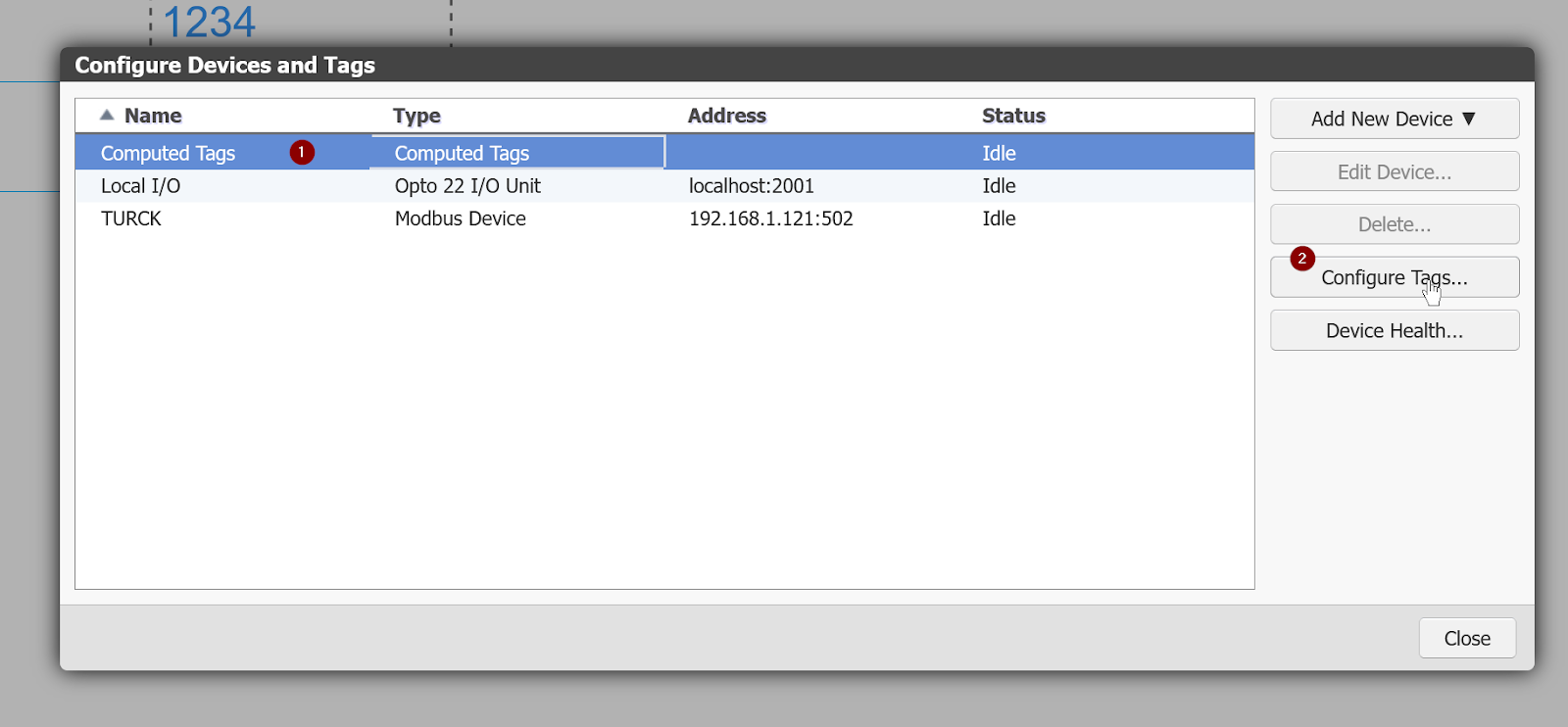
Of course, Groov view can also handle complex calculations and logic called Computer Tags: add Computer Tags, click Configure tags and add new Tags.
Click Add New Tag to add new Computer Tags.
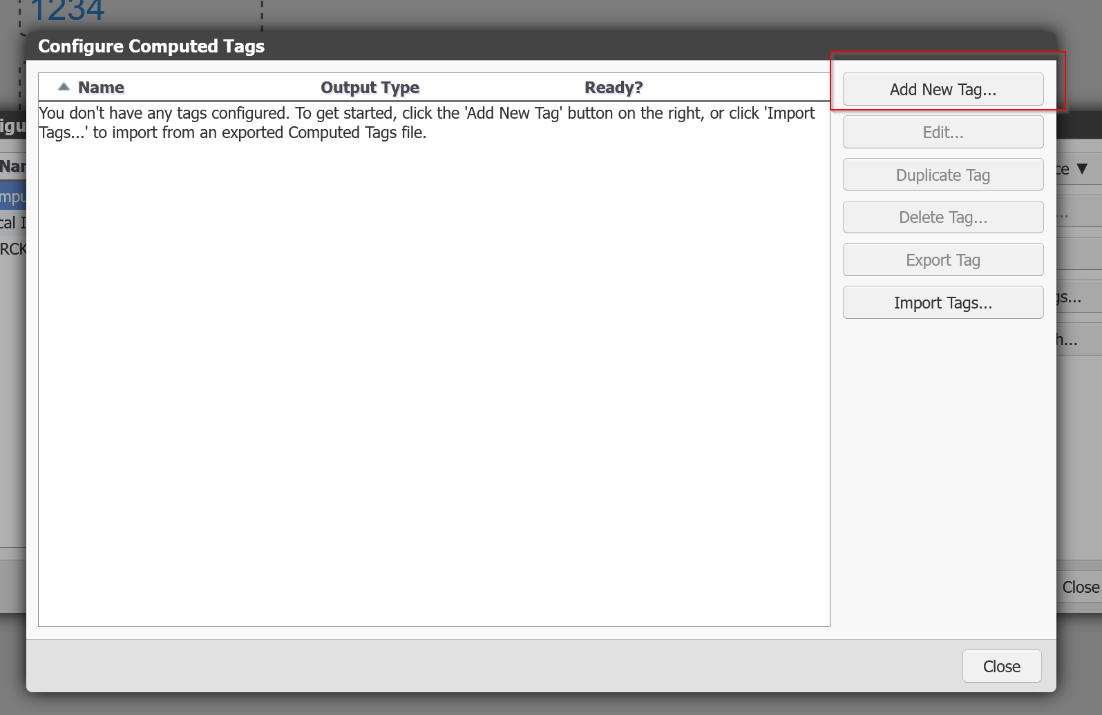
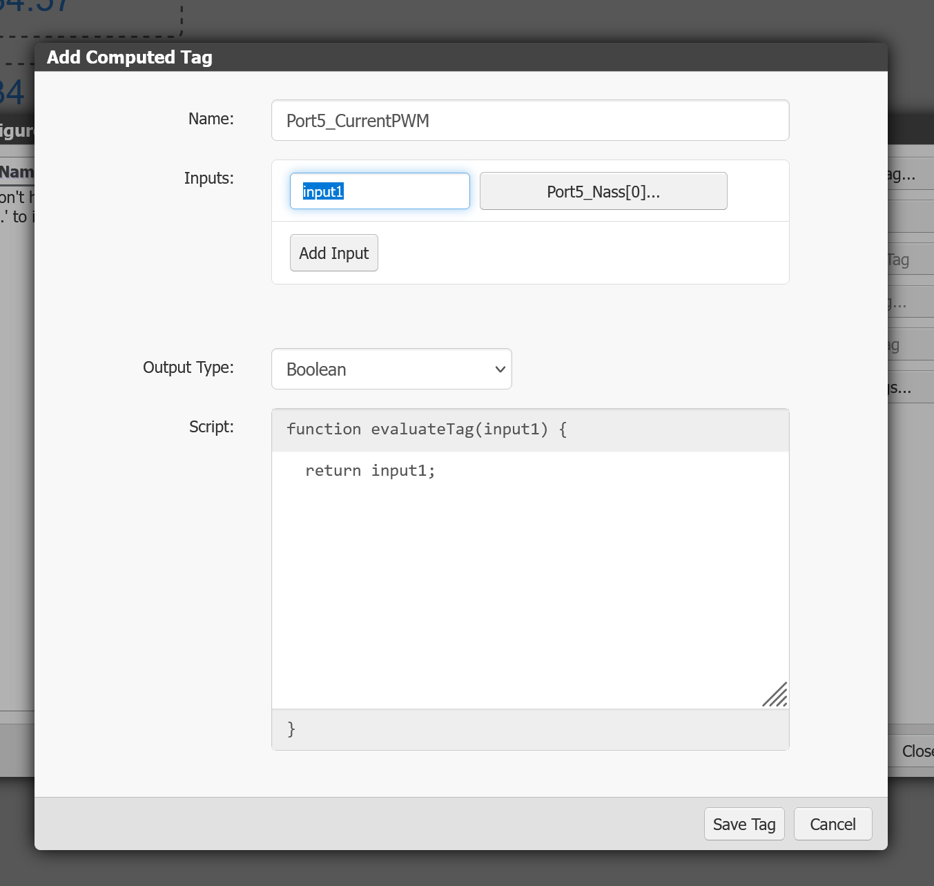
This is the Computed Tags configuration screen.
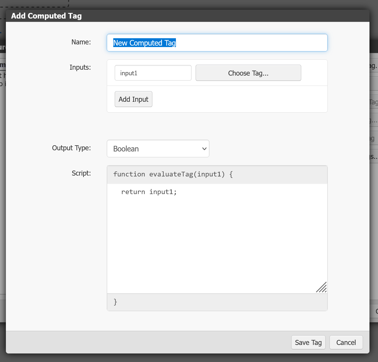
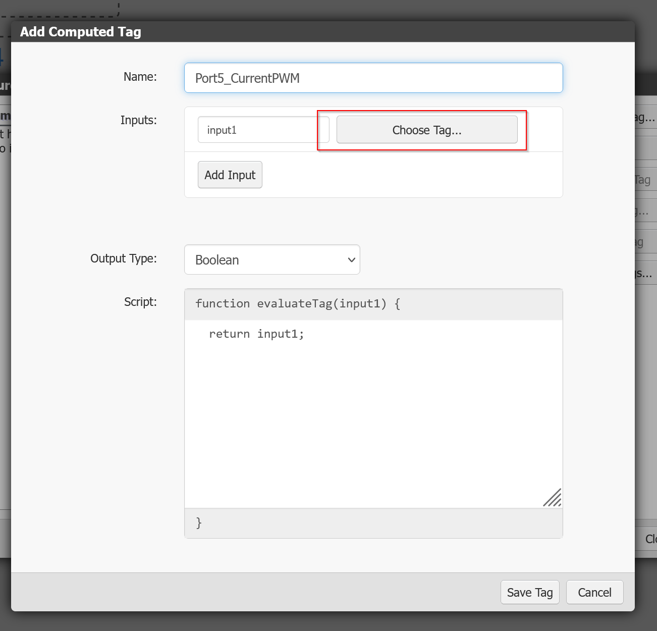
Click Choose Tag to set the Tag for the calculation and logic processing. Multiple Input parameters are also possible, but in this article only Input1 is used.
If you select Port5_Nass[16] and set >Array index to 0, the Port5_Nass[0] value becomes the Input parameter.
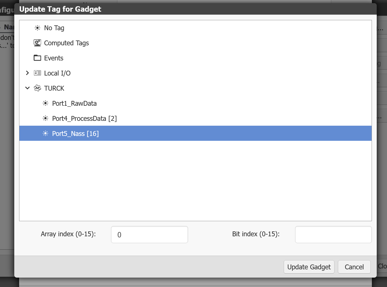
Done!
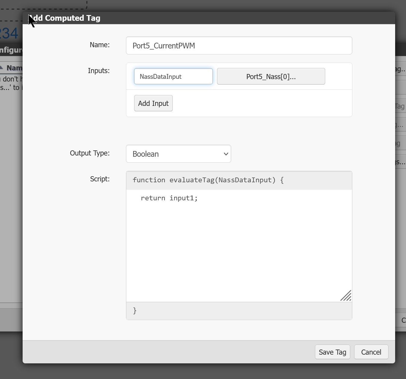
Rename the Input parameter in the Field of Inputs to an easily recognisable name.
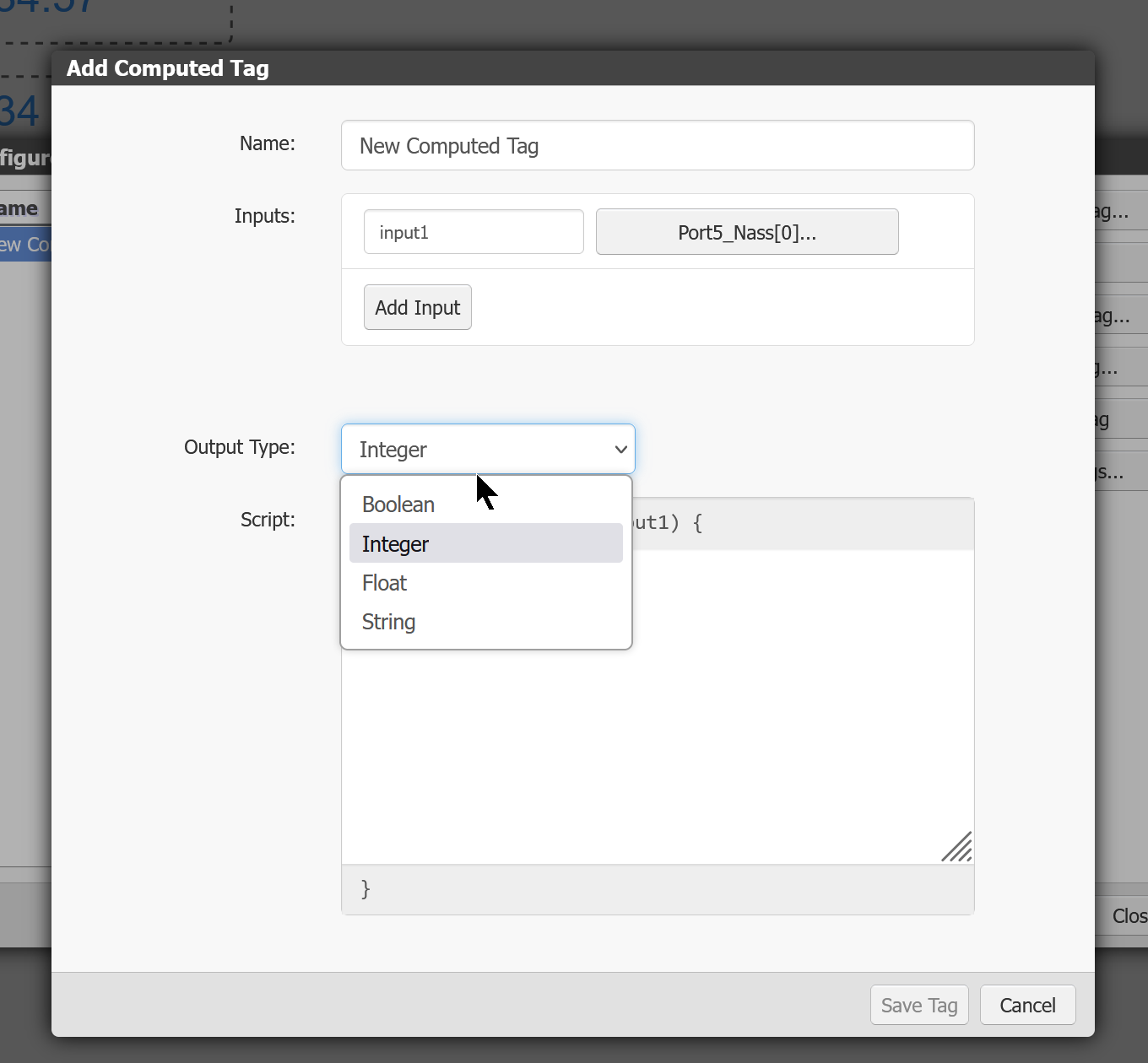
Output Type is the data type of the Return Value after the function has been executed.
In this case, it is Integer.
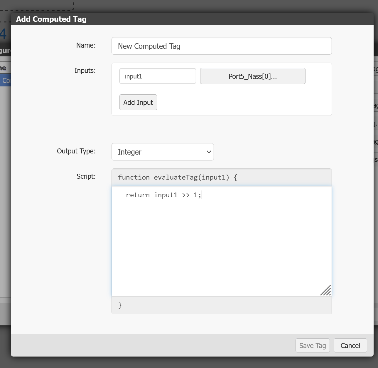
The Script is basically a Javacript, this time returning the Input value with one shifted to the right.
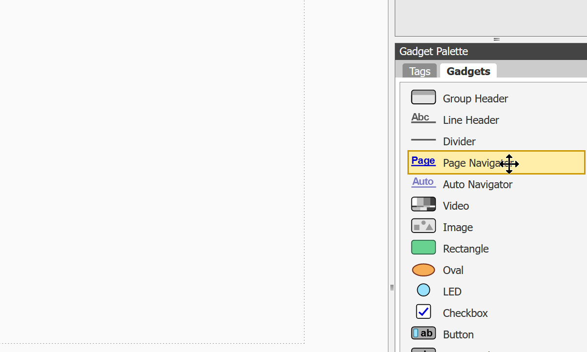
Add Page Navigate
You can switch between pages in the Groov view either by using the left Bar or by adding a Page Navigate button.
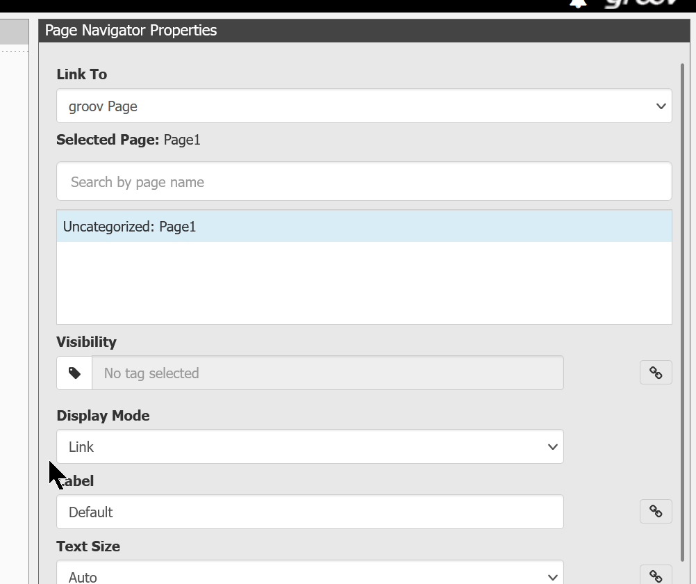
A Page Navigate button like this has been added.

In Properties, set Link To to Groov page and set the page you want to jump to in the Select Page field.
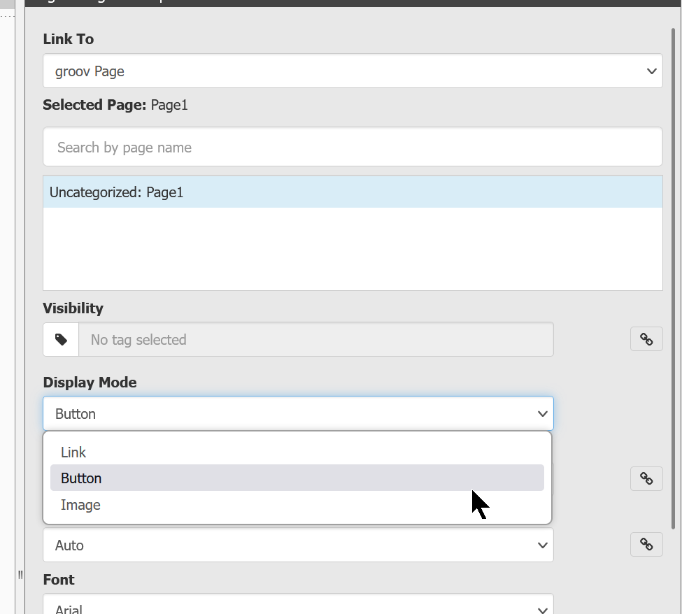
Change Display Mode to Button.
Label allows you to change the text on the button.
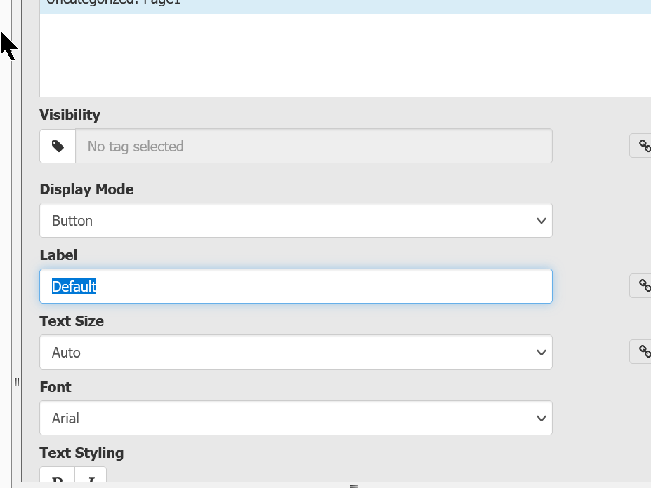
Done!
Add IO Tags
Now add the Slot data installed in the EPIC itself.
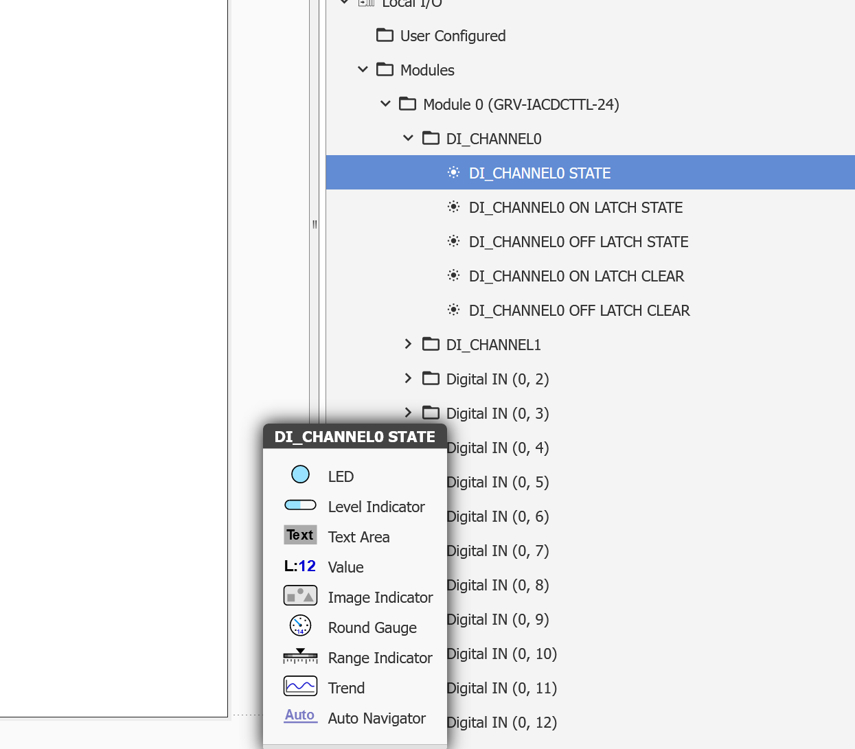
You can directly access the Channel value of each Module as Local I/O>Modules>module0.
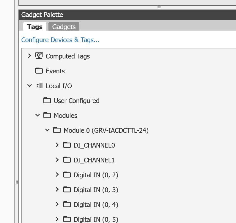
For example, add DI_CHANNEL0_STATE (i.e. the current value) for DI_Channel0.
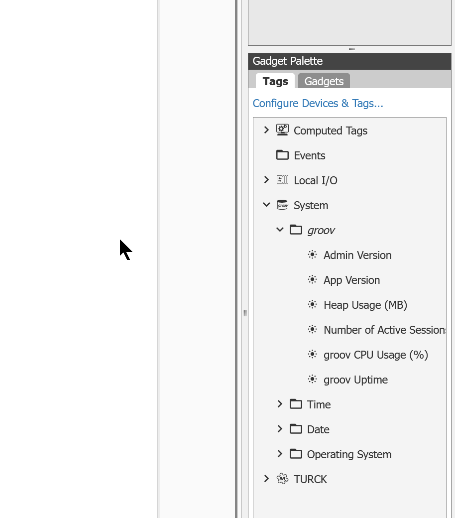
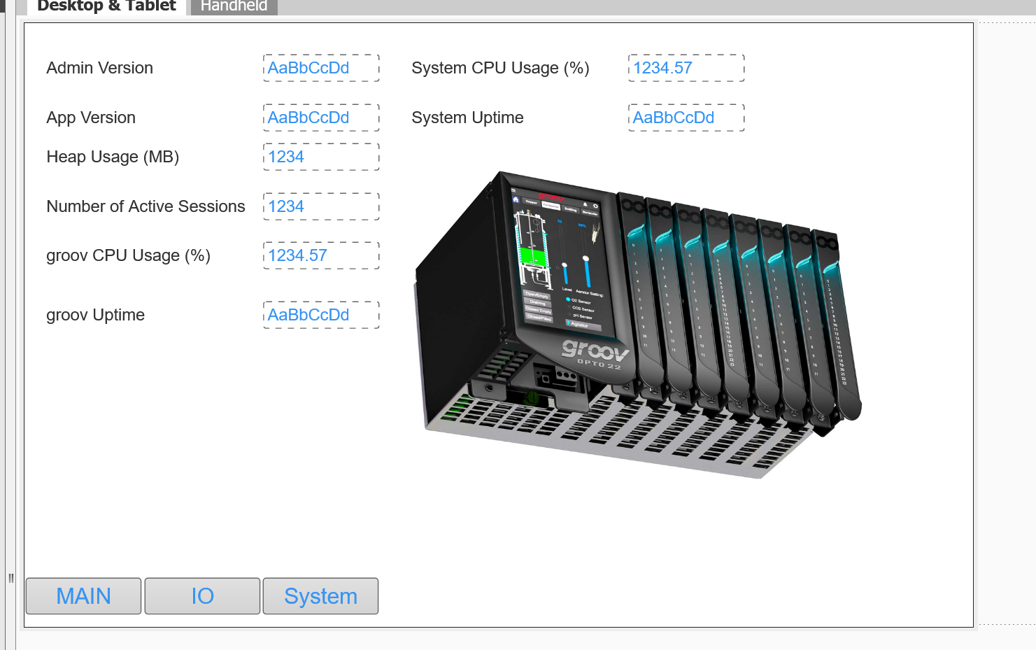
Add System Tags
You can also add System variables in the Groov view, and you can now check the status of PLCs and Modules.
Done!
Various system information can be accessed from System>Groov, for example, CPU usage and Version can be monitored in Groov View.
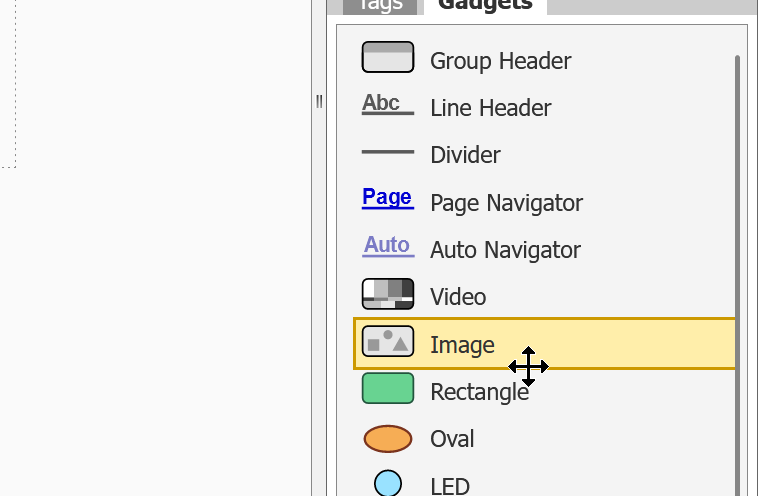
Add Images
If you want to display pixels in Groov, add an Image component in Gadgets.
Done!
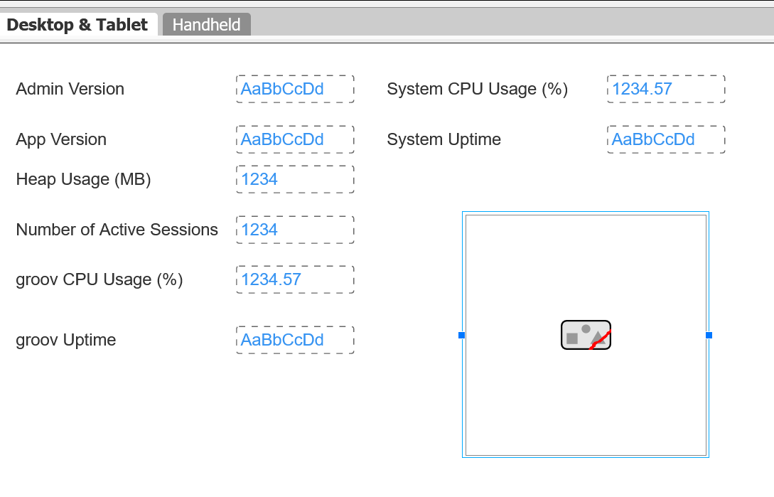
Double-click on the Image area in Image Properties.
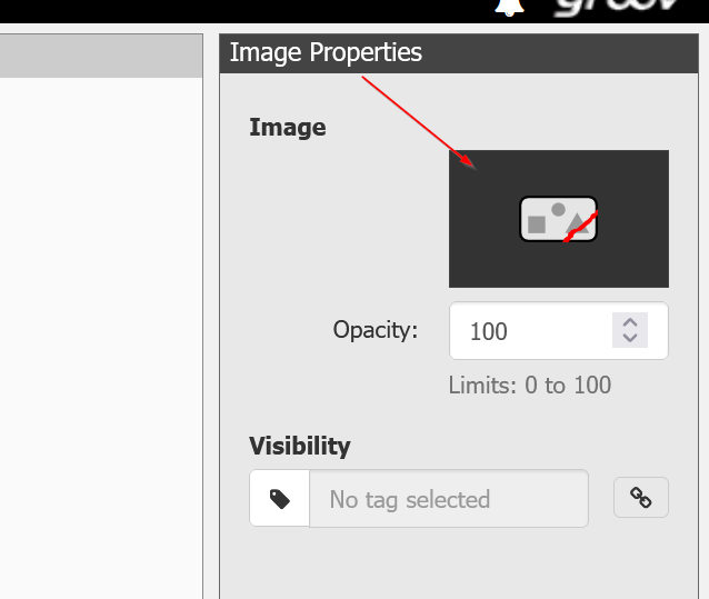
Click the Add New Images button to upload new images from your PC.
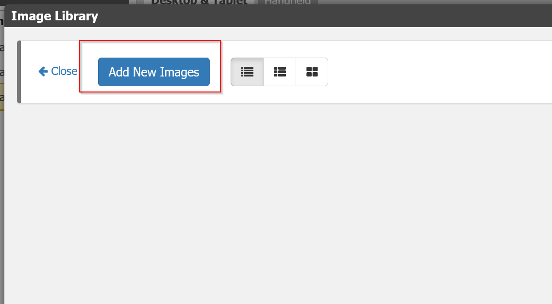
Done!
Events?
Now add an Event – think of Events as a generic HMI alarm function.
You can add an Event under Configure>Events.
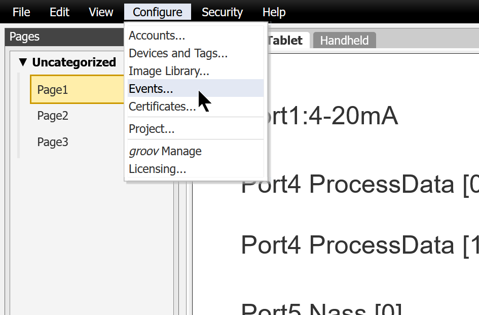
Click on the Create New Event button.
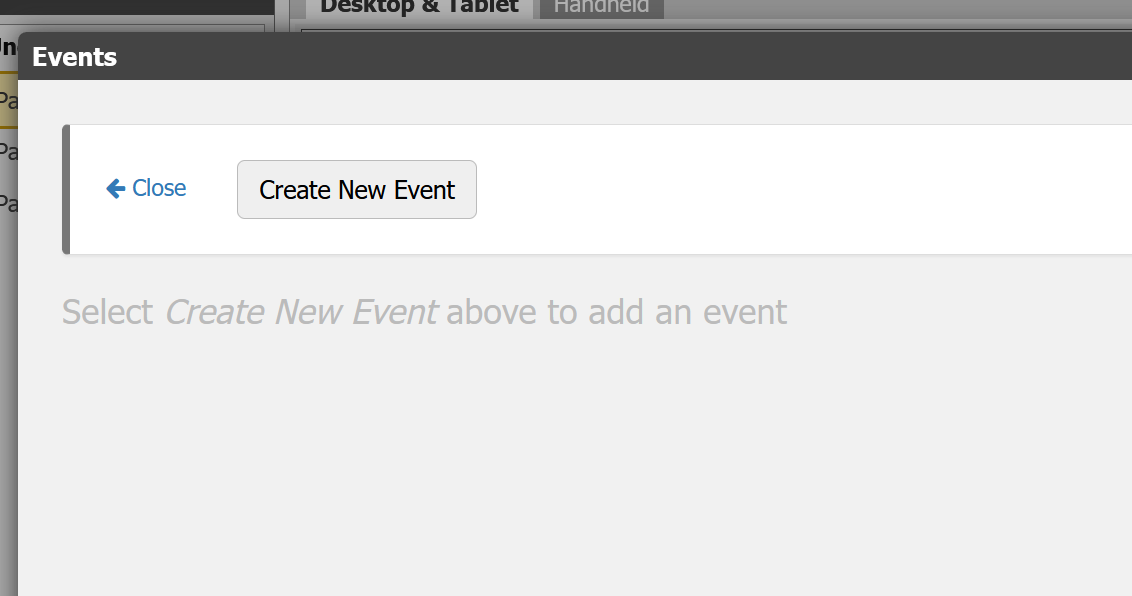
This is the Groov View’s Event settings screen.
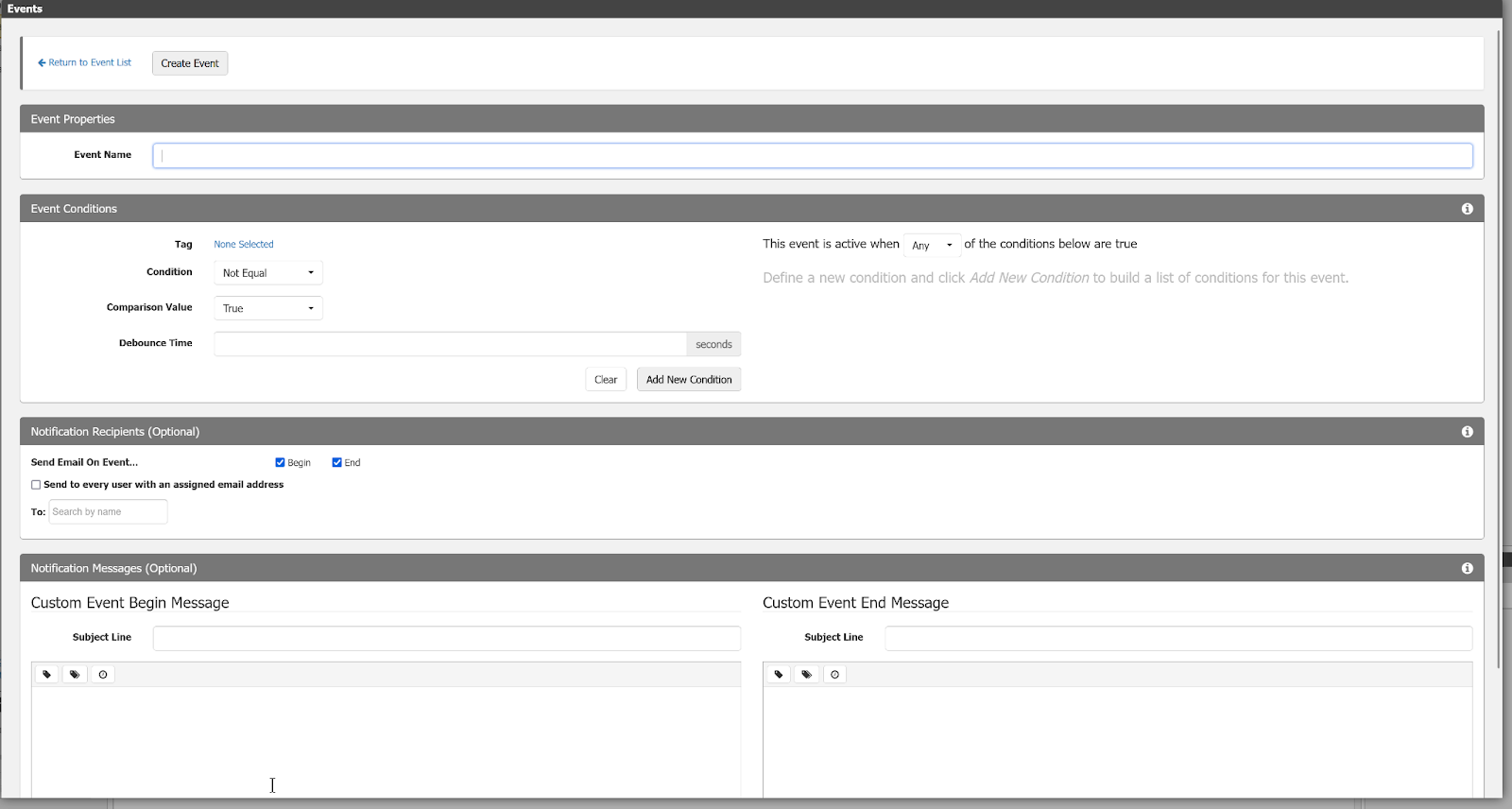
Event Name
Enter the name of the event in Event Name.
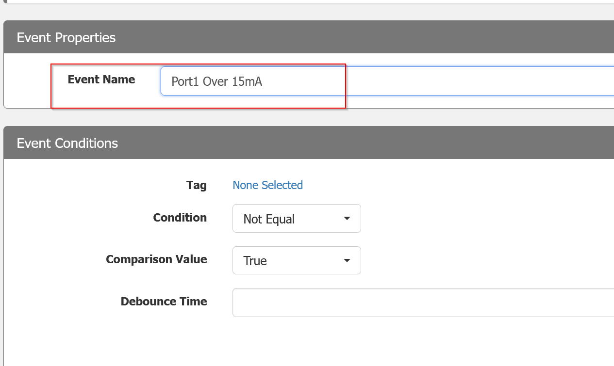
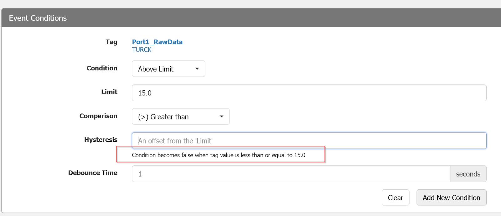
Tag
This is a Tag to be compared with Event Condition.
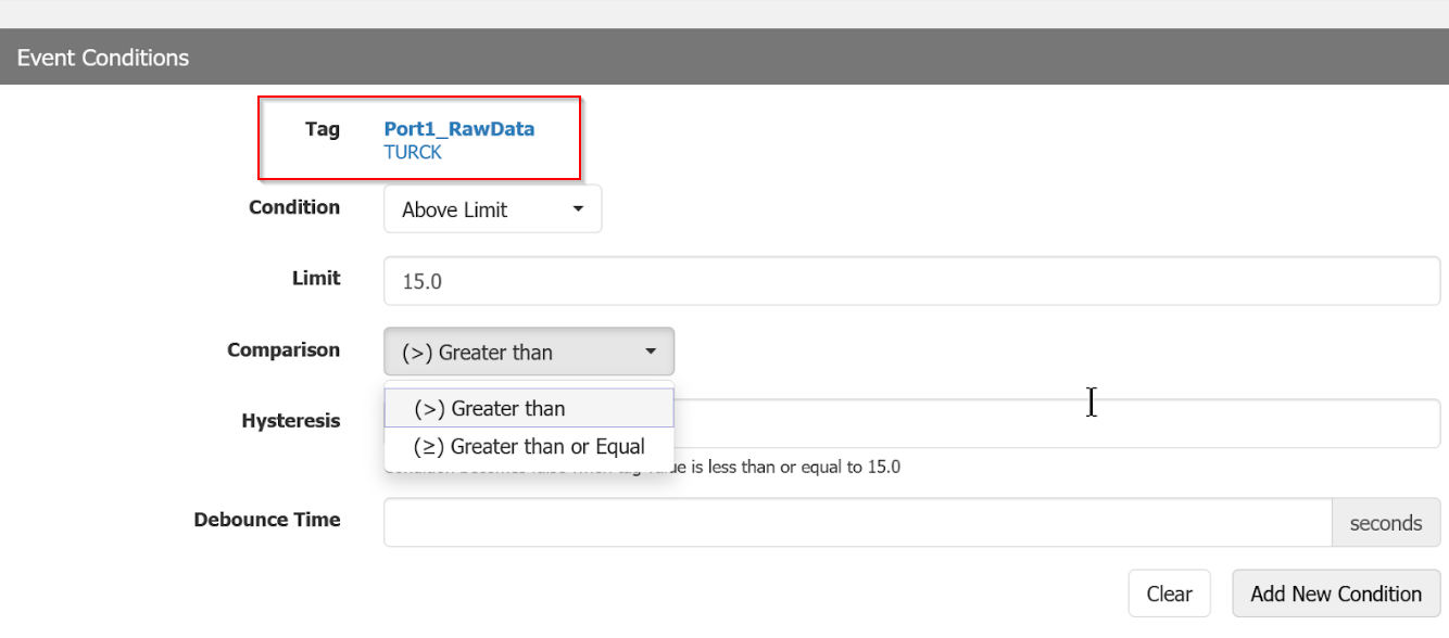
Comparison
These are the terms of comparison.
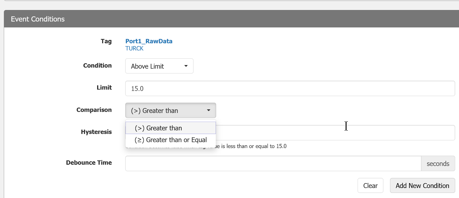
Event is set to Trigger when Port1_RawData is greater than 15.0.
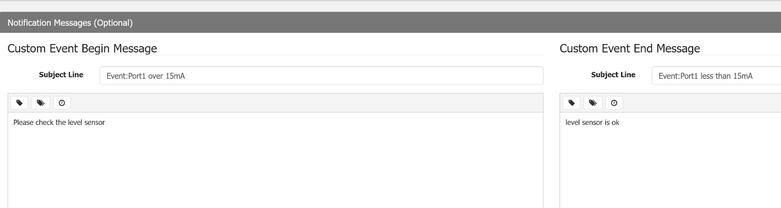
Event Message
Here you can set the characters to be displayed when an Event occurs and when an Event is canceled.
Add new Condition
Finally, use the “Add New Condition” button to add a Trigger condition for the Event you have just defined.
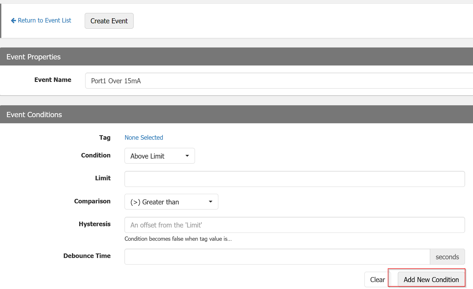
Done!
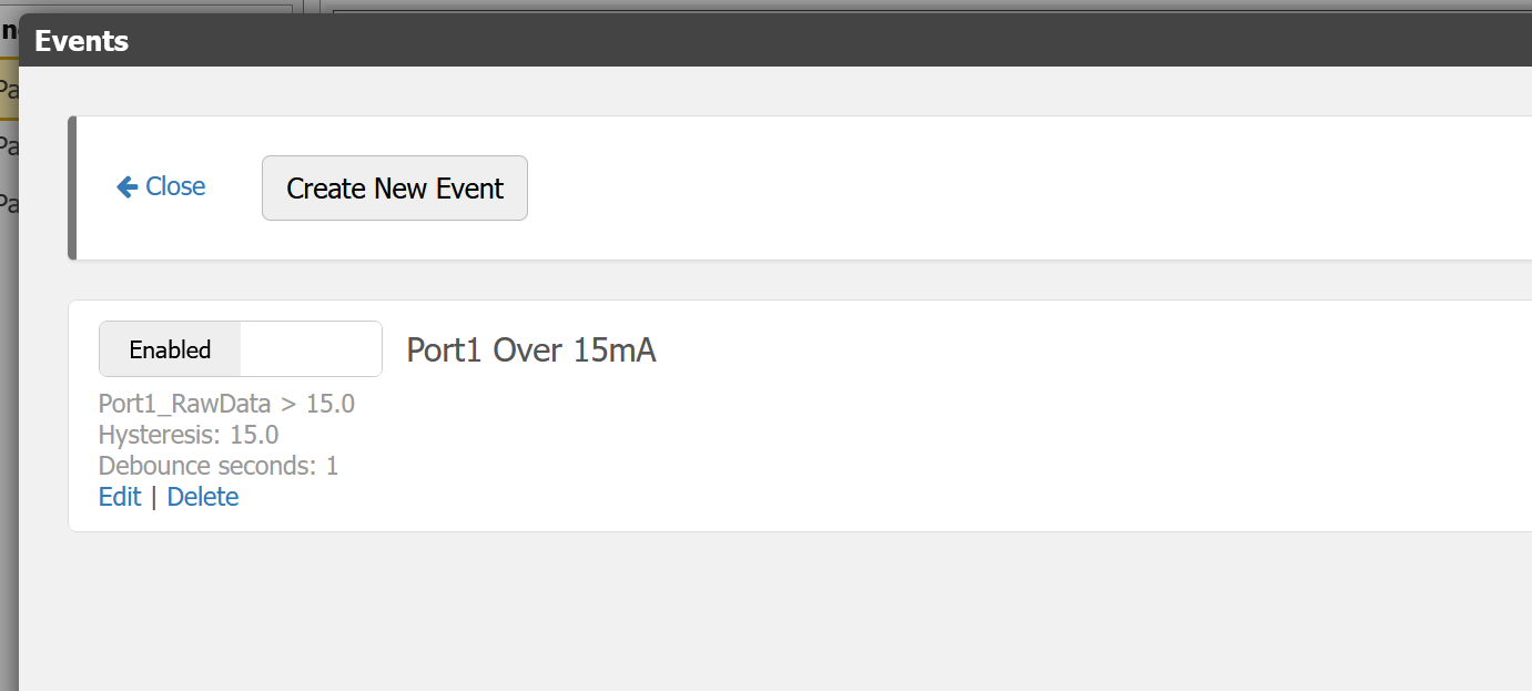
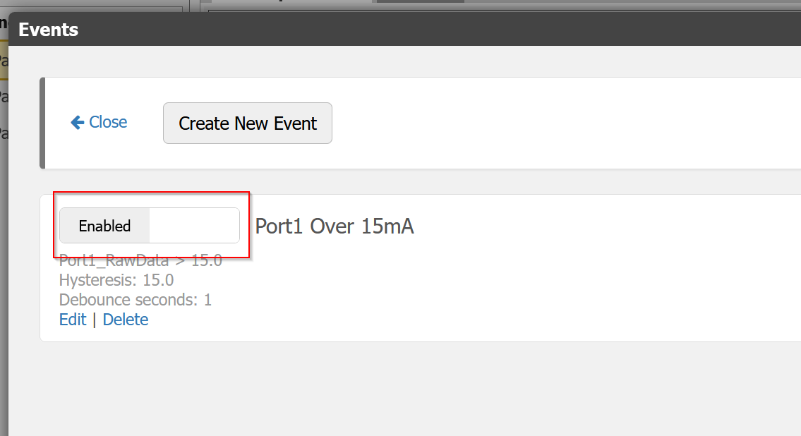
Enable
Groov View can disable and enable each Event.
Try It!
Set the current value of Port1:4-20mA to 15.0 or higher.
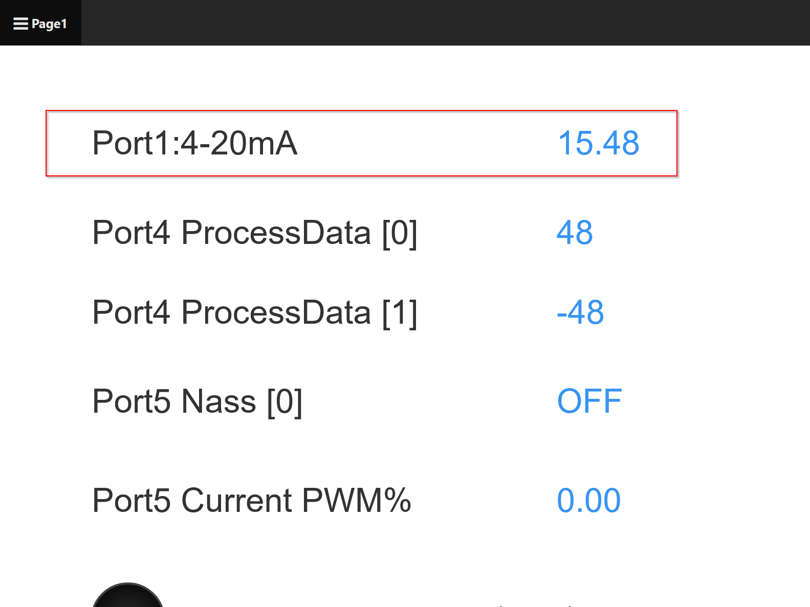
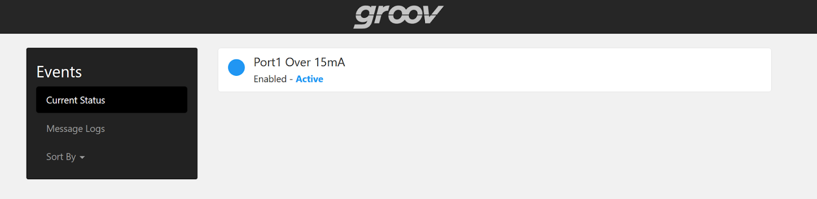
Events on the right are marked with a red “1”.
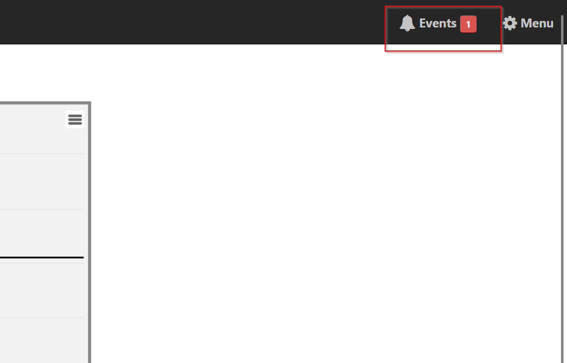
Now the message Port 1 Over 15mA is also displayed and the blue LED is on. This means that this Event is in Trigger.
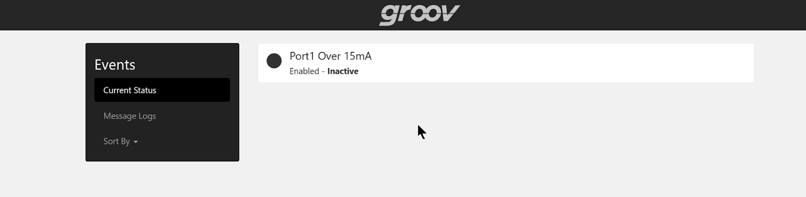
When the current value of Port1:4-20mA is less than 15.0, the LED changes to black. So this Event is not Triggered.
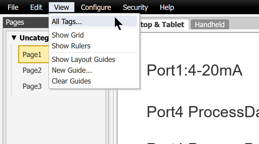
View All Tags
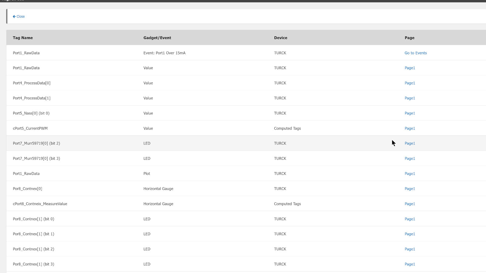
The View>All Tags function allows you to see all the Tags currently defined in the Groov View.
You will see a list like this.
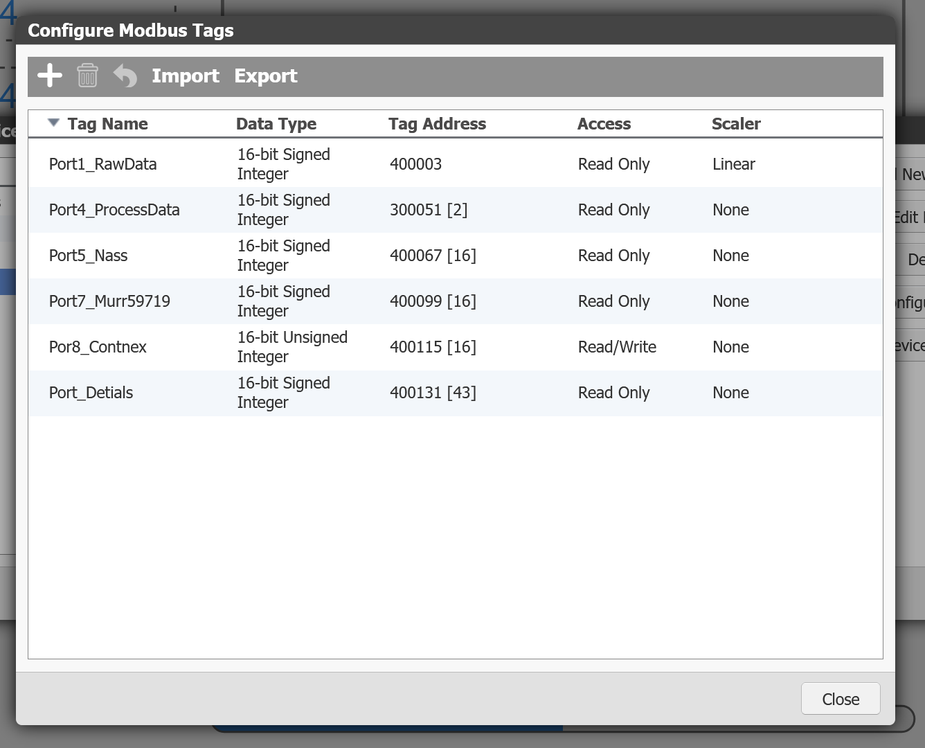
Tag setting Summary
The last section describes one Tag at a time that actually communicates with the TURCK IO-Link Master.
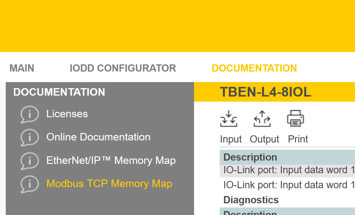
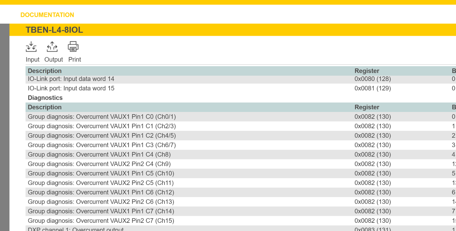
Open the TURCK IO-Link Master web server and click DOCUMENTATION>Modbus TCP Memory Map.
List the registers and their meanings in TURCK’s IO-Link Master TBEN-L4-8IOL4.
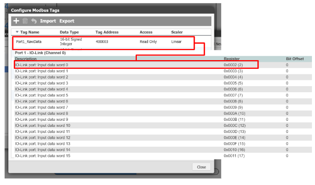
Port1
Port 1 can only be read from Tag address 400003, which corresponds to Port 0-IO-Link (Channel 0) Register 0x0002(2) of TURCK’s TBEN-L4-8IOL4.
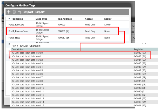
Port4
Port 4 reads two from Tag address 300051[2] and therefore corresponds to Port 4-IO-Link (Channel 6) Register0x0032(50) and Register0x0033(51) of TURCK’s TBEN-L4-8IOL4.
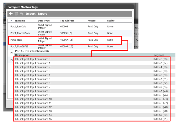
Port5
Port 5 reads 16 from Tag address 400067[16], which corresponds to Port 5-IO-Link (Channel 8) Register0x0042 (from 66) to Register0x0051 (81) of TURCK’s TBEN-L4-8IOL4.
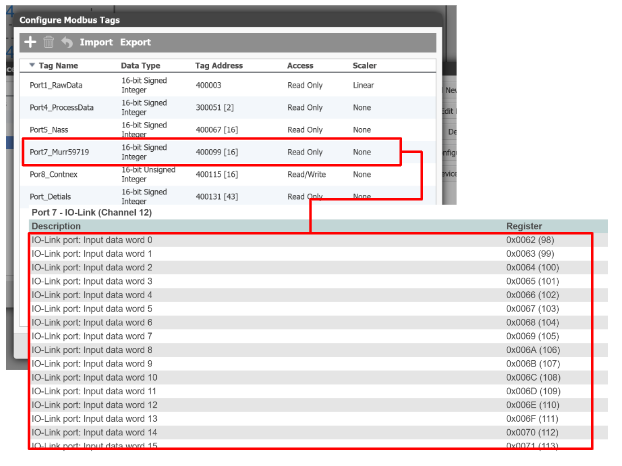
Port7
Port 7 reads 16 from Tag address 400099[16], which corresponds to Port 7-IO-Link (Channel 12) Register0x0062 (from 98) to Register0x0071 (113) of TURCK’s TBEN-L4-8IOL4.
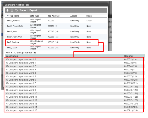
Port8
Port 8 reads 16 from Tag address 400115[16], which corresponds to Port 8-IO-Link (Channel 14) Register0x0072 (from 114) to Register0x0081 (129) of TURCK’s TBEN-L4-8IOL4.
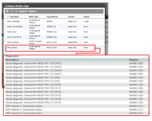
Port Details
Port Details reads 43 from Tag address 400131[43], so it corresponds to Diagnostics Register 0x0082 (from 130) and 43 Registers in TURCK’s TBEN-L4-8IOL4.
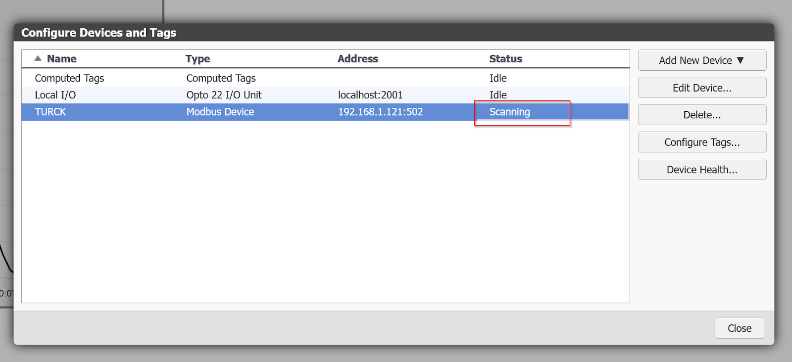
Communication State
If the connection between the TURCK device and the Groov View is successful, the Status changes to Scanning.
Result
In this video Groov View gets data from Murr’s IO-Link Converter via TURCK’s IO-Link Master.
OPTO22#Groov View montitors murrelektronik Converter Via Modbus TCP From TURCK IO-LINK Master
In this video Groov View acquires data from the Nass magnet via TURCK’s IO-Link Master.
OPTO22#Groov View montitors the NASS Devices Via Modbus TCP From TURCK IO-LINK Master
In this video Groov View acquires data with TURCK’s IO-Link Master.OPTO22#Using ModbusTCP and Groov View with TURCK IO-Link Master