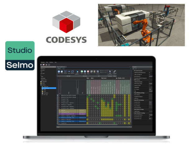
This article explains how to use Selmo Studio to generate simple programmes from Zero to work with Codesys. We will also show you a few HMI features of Selmo Studio.
Let’s Started.
Reference Link
Implementation
Machine Simulation
This is the Simulation equipment of FactoryIO this time.


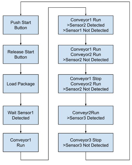
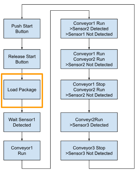
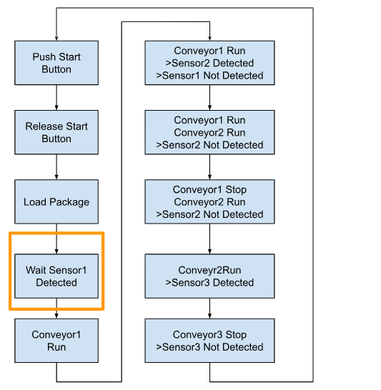
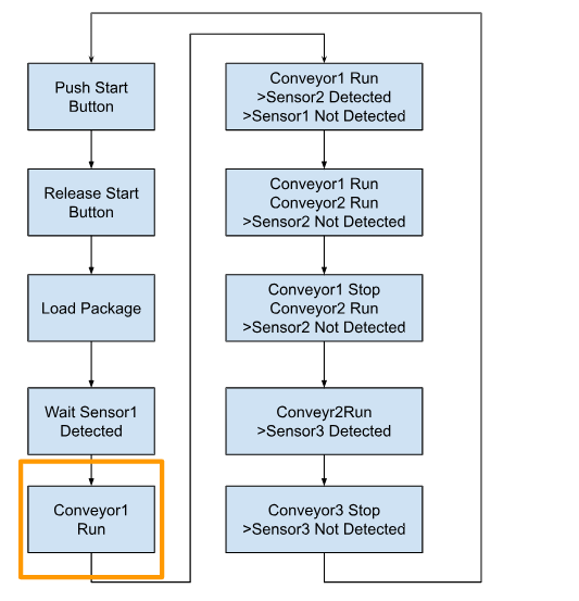
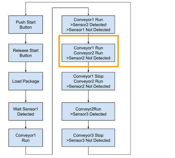
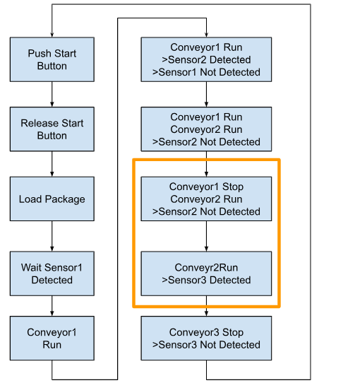
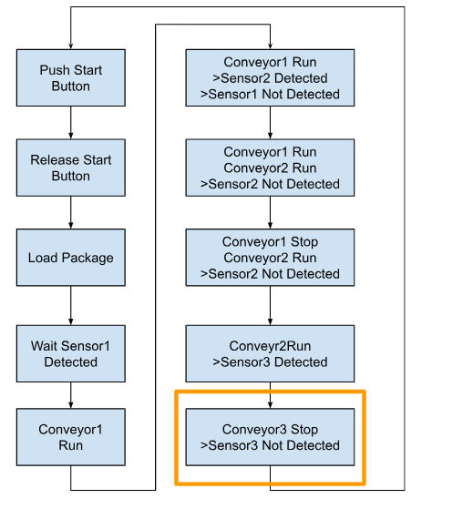
Flow
This is the Flow of this article.
Logic Layer
First create the Logic Layer.

Add Step
Add Step.

We have discussed Step in the previous article and will not explain so here.

Flow
This is the Logic Layer configuration for this article.

System Layer
Next, open the System Layer and create a Matrix table of controls.

The System Layer screen displays the Steps you have just defined.

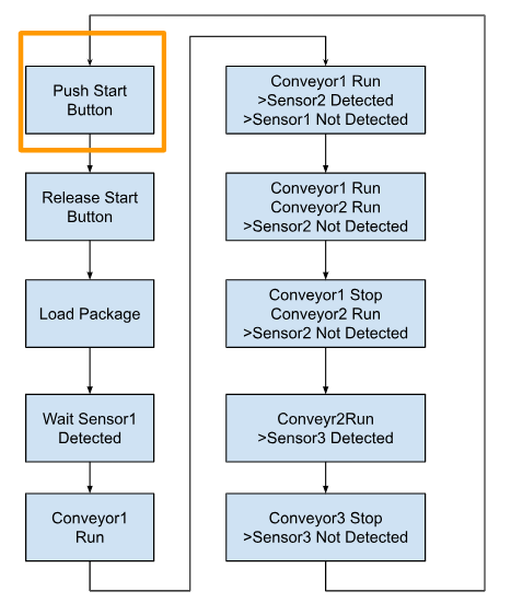
Zone1:Input, Wait the Button is pressed
Define Zone 1. This one creates the action of pressing the start button.

Add Zone In.

Zone In has been added; we have already discussed Zones in a previous article, so we won’t go into detail here.

Set an appropriate name for the Zone In.

Set the name of the Zone In and set the Zone Input to “i_xStartButton”.
The “i_xStartButton” becomes an Input signal.

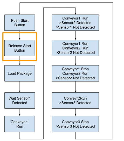
Zone2:Input, Wait the Button is Released
Define Zone 2. This one creates the action of pressing the start button and then releasing it.
Add a Zone In as before and define a suitable name.

Set Zone Input to the same signal as i_xStartButton in Zone 1 and put a Checkbox for Input inverted. That means that the inverted signal of i_xStartButton is monitored, i.e. False = condition satisfied.

Done!Inverted zones with an input signal have a blue Icon.

Set S for Zone 1 and Zone 2.

Group your Zones
Multiple zones can be grouped and managed according to application behaviour. Select multiple zones to group and click >Edit Zone.

Set Group Name and confirm with >Ok.

Done!

Zone3:In-OutLoad the Packages
Define Zone 2. This one creates the behaviour that generates the Package for FactoryIO.

Add Zone In-Out.

Done!This zone is assigned to Step 3 “Generate boxes”.

Set the signal of Zone Input to Inverted i_xSensorB1.
Set the signal of Zone Output to o_xLoadPackage.
This means that o_xLoadPackage is set to True, i_xSensorB1=False (Sensor has detected the box), proceed to the next Step.

Fully qualified variable name will actually be the variable name of the input/output of the relevant Zone when output as PLC XML Format.

Done!

Zone4:Input,Wait Sensor1
Define Zone 4. This one creates the behaviour of Sensor1 detecting the box.

Add Zone In.

Define Zone Input as i_xSensorB1.

This zone is assigned to Step 4 “Transport boxes to Conveyor 1”.

Zone5:In-Out,Transfer package to Conveyor End
Define Zone 5. This is where Conveyor 1 creates the operation to transport the boxes.

Define Zone In-Out.

The next step is to create a behavior that outputs Conveyor 1 until Sensor 2 is True (box detected).
Define Zone Input as the inverted signal of i_xSensorB2.
Define Zone Output as o_xConveyro1.
Then set the Zone Output to Output Group “Conveyor1”.

Zone 5 was defined and assigned to Step 4.

Zone6:In-Out,Transfer Package Between Conveyor1 and Conveyor2
Define Zone 6. This one creates the operation to transport the boxes with Conveyor 2, as the boxes cannot be transported from Conveyor 1 to Conveyor 2 unless Conveyor 1 and Conveyor 2 are switched on at the same time.

Define Zone In-Out.

Define Zone Input as i_xSensorB2 signal.
Define Zone Output as o_xConveyro1.
Then set the Zone Output to Output Group “Conveyor1”.

Zone 6 is allocated to Step 5 Transfer Package Between Conveyor1 and Conveyor2.

Zone7:In-Out,Transfer It to End of Conv2
Define Zone 7. This zone creates a behaviour where Conveyor2 turns ON until Sensor3=True (box detected).

Define Zone 7. This is where Conveyor2 creates the operation to transport the boxes.

Define Zone Input as the inverted signal of i_xSensorB3.
Define Zone Output as o_xConveyro2.
Then set the Zone Output to Output Group “Conveyor2”.

Zone8:End
Define Zone 8. This zone creates a behaviour where Conveyor2 turns ON until Sensor3=False (the box has been carried away).

Define Zone In-Out.

Define Zone Input as i_xSensorB3 signal.
Define Zone Output as o_xConveyro2.
Then set the Zone Output to Output Group “Conveyor2”.

Output Group?
The Output Group is explained here.

This is the Output with Group settings.

This is the Output without Group settings. As you may have noticed, instead of outputs with Group settings being output under OR conditions, outputs without Group settings are output directly from the Method of the Selmo Basic Library.
So, if you want to control the same output ON/OFF in multiple Zones, you need to set Group. If you do not make that setting, the output update behavior will be strange.

Generate Code
Having reached this point, use Generate PLC-Code to generate the PLC code.

Import the PLC Code
With the Application selected, click Project>Import PLCOpenXML.

Select all and proceed with OK.

Done!

Import Libaray into Codesys
Export the Selmo library from Codesys in Selmo Studio and install it in Codesys.

Click on Libarary Repository.

Click Install.

Select the library you have just Exported.

The last step is to add Selmo Basic Libaray in Add Library.


Program
Next, call GlobalControl() and GlobalUtilities().

Configure OPC UA in Factory IO
Configure the FactoryIO as an OPC UA Server.

Mapping IO to OPC UA Server.

Configure the OPC UA Target
Set the Hardware to be Codesys Targeted in Target System.

Generate HMI
This article does not explain how to set up an HMI, but Selmo Studio can generate one automatically; click on Generate HMI and start the executable.

Done!The HMI has been automatically generated and activated.

Go to Auto Mode
Click on the button in the red frame to expand Menu.

Done!

Click Autom to shift the system into AutoMode.

The operation is shown in the diagram below.

Start!
Start by pressing and holding the HWZone button for 3 seconds!

Done!Sequence activated.

Monitor From Selmo Studio
The current status can be monitored from Selmo Studio by clicking on the Connect to PLC button in the System Layer.

Done!

Result
You can see it in action in this video.